Embed Size (px)
Citation preview
Automated 3D Reconstruction of Moving RigidSpecimen from RGB-D Video Input
Erika HarrisonDepartment of Computer Science
University of CalgaryCalgary, Canada
Faramarz SamavatiDepartment of Computer Science
University of CalgaryCalgary, Canada
Jeffrey BoydDepartment of Computer Science
University of CalgaryCalgary, Canada
Abstract—To assist morphometric and behavioural analysis of live
animals, we present an automatic process for generating a 3Dvolumetric representation of a dynamic rigid specimen fromRGB-D video. This process uses multi-feature extraction andautomatic labelling through a novel distance matrix structureand rigid transformation validation to reduce maximal cliquecalculations. An adapted SiftFu implementation then incorpo-rates the resulting rigid transformations to perform the finalvolumetric reconstruction. Validation occurs using an RGB-Dsequence from a living leopard tortoise resulting in a smoothlymerged and textured volume from the original RGB-D frames.
Index Terms—3D reconstruction; rigid transformations; ani-mal RGB-D video capture
I. INTRODUCTION
The biological sciences are tasked with studying animals inlaboratory and wildlife settings while constrained to minimizeimpact and interaction of their specimen. Modern technologyis reaching sufficient advancement to assist in live acquisi-tion and computational reconstruction of real-world specimenmodels for tracking, analyzing and archiving. However, bio-logical specimen vary in shape and form, and their precisemorphometric configuration is often unknown.
To assist with non-invasive, automated support for 3D analy-sis of animals, we present a frame-to-model multi-step processfor general specimen reconstruction involving: initial RGB-Dframe capture; multi-feature identification through point-pairdistance tracking and feature point rigid object labelling; andper-object volumetric representation. This is useful for visualcapture and analysis for biological studies where animals areable to move at will, and input is often limited in the numberof cameras, and therefore viewing perspectives.
The main contributions of this work is presenting a cohe-sive, automated process to convert RGB-D input into a finalvolumetric representation; and its application to live specimen.
II. RELATED WORK
Increasingly sophisticated techniques are being developedfor 3D reconstruction using modern RGB-D camera input.Its application to animals, however, is relatively limited. Forexample, Winter [14] uses a laser scanner to reconstruct ataxidermy owl, while Falkingham [3] explores the low-costRGB-D Kinect v1.0 to scan fossils. While these examples
are valuable at demonstrating post-construction measurementaccuracy, they are limited to stationary specimen.
For moving animal scenes, Fernandez et al. [4] explorelaboratory rodent segmentation from point cloud information.Ross et al. [10], does not employ depth information, howeverthey are able to identify rigid motion articulations of giraffesusing their extraction system. Lastly, while the work of Duoet al. [2] emphasize 3D reconstruction of highly detailedmotions from RGB-D video capture, it does demonstratepotential application to animals with their real-time caninereconstruction. However, it requires multiple cameras andits full-surface reconstruction does not support separation ofmotions, needed for any subsequent analysis.
To perform 3D reconstruction from RGB-D footage, a num-ber of related works must be considered. For other examplesof range image registration, see the survey of Salvi et al. [12]For the initial camera input, Khoshelham and Elberink [5]provide technical descriptions and accuracy evaluations ofthe Kinect 1.0. Registration between frames occurs usingdifferent types of feature points, described by Krig [6]. Toidentify rigid transformations, Perera and Barnes [9] describean approach using point-pair distances and max-clique finding.Our work employs rigid transformation detection, inspiredby the efficient calculations of Sorkine [13], to speed upthe process and improve accuracy. Lastly, visualization usinga volumetric representation is computed using the truncatedsigned distance function, as used in other works, such asNewcombe et al. [8] and the SiftFu work of Xiao et al. [15].
Note, whereas Chiari et al. [1] use stereo RGB images asinput on stationary tortoise carapace, this work reconstructs afreely moving tortoise using RGB-D sequences.
III. METHODOLOGY
Converting a sequence of RGB-D images to a volumetricrepresentation requires a number of stages. Firstly, we estab-lish how frames relate by finding correspondences betweenthem (Figure 1). Secondly, we identify rigid motions by identi-fying point correspondences residing on common rigid objects.This involves a single matrix representation for tracking andprocessing all correspondence points. Lastly, each rigid motiontransforms the RGB-D images into a common volume for afinal, textured volumetric representation.

Fig. 1. Example of feature points matched across frames.
A. Initial Capture
RGB-D information is gathered using the low-cost Kinect1.0, modified to work on portable battery, facilitating mobilecapture. Each frame results in a 2D RGB image as well as a16 bit 2D image which can be converted to depth.
To increase the quantity of points available for correspon-dence between frames, the RGB images are processed usingseven (7) different feature-point extraction methods - SURF,MSERF, MinEigen, Harris, FAST, BRISK and SIFT, spanningthe popular SIFT plus all feature types readily available inMatlab. For the provided sequences, we work with featurepoints visible in all frames. Feature points which disappearfrom view are discarded from consideration. Notice in Figure 2that after features from Figure 1 of invalid depth are removed,the number of available features dramatically falls off tomaintain inter-frame correspondence. This motivates the useof multiple types of features to improve correspondence andresulting reconstruction quality.
Fig. 2. Reduction of total features from Figure 1 sequence, after discardinginvalid depth, and then matching across frames.
B. Feature Labelling
Labelling of features refers to the identification of fea-ture points undergoing a common rigid transformation acrossframes. Feature points with the same transformation are giventhe common label. This is fundamental in identifying regionsof the RGB-D images which reside on the same rigid object.
For the resulting n features, their 3D coordinate is computedby projecting using the depth map and camera specifications.This results in an Euclidean coordinate in metres, (0, 0, 0)centered at the camera, with the z-axis projecting out fromthe camera, the y-axis projecting up from the camera, and x-axis perpendicular to both and right of the camera’s view. Theresulting 3D feature coordinates are then used to populate ann × n symmetric matrix D storing the point-pair distances.The point-pair distances in the matrix are updated each frame,
as the feature points may have changed position relative toeach other as would be expected in a dynamic scene. Figure 3illustrates an example of how the distance matrix is updatedbetween frames. Notice that the camera position may change,as the point-pair distances are relative to the pairing, andunrelated to absolute coordinates.
Fig. 3. Illustrative example of algorithm used for identifying rigid bodies.
Observe that for rigid bodies, distances of points on thesame rigid body remain constant. As the distances are updatedfor each frame, if a distance significantly differs from a priorframe, the values are flagged as invalid. This corresponds totwo points not residing on the same rigid body.
Whereas Perera and Barnes [9] identify trial-and-errorsequence-specific thresholds using standard deviation and av-erages, an error threshold based on error metrics intrinsic tothe Kinect camera are used to identify signficant differences.From Khoshelham and Elberink [5], the error function for apoint z metres from the camera on the z axis, is expressed as:
Ez(z) = (1.87z2 − 1.84z + 2.21)× 10−3. (1)
Notice this error changes with distance and position fromthe camera. While Khoshelham and Elberink [5] describe howto calculate the errors Ex, Ey for x and y respectively, exper-imentation demonstrates that their contribution is negligibleand we use Ez to represent the error for a 3D coordinate. Asfeature points may be at different z distances, and therefore

different errors, we use standard error propagation from thepoint-pair distance calculation to produce:
E(z1, z2) = Ez(z1) + Ez(z2) (2)
for z1, z2 the z coordinates of the respective 3D feature points.E is then used as our error threshold for identifying significantdifferences between frames, and must be computed for eachframe and each point-pair. Figure 3 illustrates how point-pair(v2, v4) becomes invalid in frame f1. Figure 4a-e illustratesdistance matrix updating of the Figure 1 sequence.
An adjacency matrix graph representation is computed by:
Ai,j =
{1, if Di,j > E(zi, zj)
0, otherwise(3)
from the n × n distance matrix D. Figure 4f illustrates anexample of such a resulting adjacency matrix. Edges representpoint-pairs likely belonging to the same rigid object, or notyet observed to be on different objects. Whereas Perera andBarnes [9] immediately apply the maximal cliques algorithmto their adjacency graph, we speed up the process by:
• Identifying connected components, efficiently computingrigid transformations [13], and computing residuals toidentify if all points are on a common rigid object
• For points not identified above, performingtransformation-residual checks on objects identifiedin a prior frame
• For points not identified above, computing max cliquesfrom the adjacency graph, and using the transformation-residual to confirm rigid transformations.
In performing transformation checks, the possibly exponen-tial time for finding max cliques within the graph is reduced.
Fig. 4. a-e. Frames 1-5 visualizing distance matrix. Black indicates point-pairdistance exceeding error threshold. f. Visualization of resulting adjacency ma-trix. g. Visualization of adjacency matrix after clique finding, rigid validationis applied. Using the presentation format from SiftFu.
At this point, feature points from the original RGB-Dsequence have been automatically labelled for each calculatedobject. Figure 5 illustrates the initial adjacency graph (a) whichis pruned using the distance matrix to the resulting labelledgraph (b), and with points labelled for each of the objects.It is worth noting that this process does not require a prioriinformation on the number of rigid objects present.
Fig. 5. a. Initial adjacency graph; b. Updated adjacency graph with labels; c.Labelled feature points in 3D space.
C. Conversion to Volumetric Representation
To construct a fully 3D representation of the resultingobjects an adaptation of the truncated-signed distance (TSDF)SiftFu approach of Xiao et al. [15] is used. This results in atextured volumetric representation of each object.
Note that SiftFu relies on SIFT features and RANSAC foridentifying a rigid transformation with which to transform thedepth information into the TSDF-calculated volume. Instead,for each of the identified rigid objects a volume is created, andthe object’s corresponding per-frame rigid transformation isused to transform the depth information in the volume. Readersare directed to the SiftFu work of Xiao et al. [15] for furtherdetails on converting RGB-D to TSDF-calculated volumes.
Fig. 6. Visualization of TSDF output across frames. Using presentation formatfrom SiftFu [15].
D. Validation
A leopard tortoise at the Calgary Zoo was filmed usinga Kinect 1.0 device. To maximize frame count and overlap-ping feature points, five consecutive frames were manuallyextracted to illustrate the reconstruction process. Computationwas performed on Matlab using a 64-bit Intel Core i7-3770with 16 GB RAM. Matlab implementation for the followingwere used: SIFT [7], SiftFu [15] - adapted for this work, andPoint Cloud Library [11] - for RGB-D to 3D projection.
IV. RESULTS
From Figure 6, observe how the holes on the surfacerepresentation decrease as more frames of input are aligned.Also notice how the posterior of the specimen initially isnot visible. As more surface is made visible to the camera,the reconstruction is able to incorporate and amalgamate theadditional surface information. This results in a whole modelvolume representation of the observed surface of the tortoise.
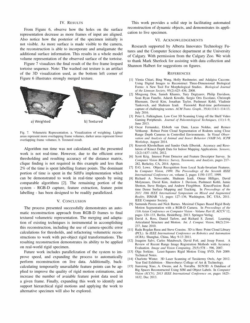
Figure 7 visualizes the final result of the five frame leopardtortoise sequence. Note: The washed out texture is an artifactof the 3D visualization used, as the bottom left corner ofFigure 6 illustrates strongly merged texture.
Fig. 7. Volumetric Representation. a. Visualization of weighting. Lighterareas represent more overlapping frame volumes, darker areas represent feweroverlapping frame volumes; b. Textured result.
Algorithm run time was not calculated, and the presentedwork is not real-time. However, due to the efficient errorthresholding and resulting accuracy of the distance matrix,clique finding is not required in this example and less than2% of the time is spent labelling feature points. The dominantportion of time is spent in the SiftFu implementation whichcan be demonstrated to work in real-time speeds by usingcomparable algorithms [2]. The remaining portion of thesystem - RGB-D capture, feature extraction, feature pointlabelling - has been designed to be readily parallelized.
V. CONCLUSION
The process presented successfully demonstrates an auto-matic reconstruction approach from RGB-D frames to finaltextured volumetric representation. The merging and adapta-tion of existing techniques is instrumental in accomplishingthis reconstruction, including the use of camera-specific errorcalculations for thresholds, and refactoring volumetric recon-structions to work with per-object rigid transformations. Theresulting reconstruction demonstrates its ability to be appliedon real-world rigid specimen.
Future work includes parallelization of the system to im-prove speed, and expanding the process to automaticallyperform reconstruction on live data. Additionally, back-calculating temporarily unavailable feature points can be ap-plied to improve the quality of rigid motion estimations, andincrease the number of avaiable feature point data used ina given frame. Finally, expanding this work to identify andsupport hierarchical rigid motions and applying the work toalternative specimen will also be explored.
This work provides a solid step in facilitating automatedreconstruction of dynamic objects, and demonstrates its appli-cation to live specimen.
VI. ACKNOWLEDGEMENTS
Research supported by Alberta Innovates Technology Fu-tures and the Computer Science department at the Universityof Calgary. With permission from the Calgary Zoo. We wishto thank Mark Sherlock for assisting with data collection andShannon Halbert for suggestions on figures.
REFERENCES
[1] Ylenia Chiari, Bing Wang, Holly Rushmeier, and Adalgisa Caccone.Using Digital Images to Reconstruct Three-Dimensional BiologicalForms: A New Tool For Morphological Studies. Biological Journalof the Linnean Society, 95(2):425–436, 2008.
[2] Mingsong Dou, Sameh Khamis, Yury Degtyarev, Philip Davidson,Sean Ryan Fanello, Adarsh Kowdle, Sergio Orts Escolano, ChristophRhemann, David Kim, Jonathan Taylor, Pushmeet Kohli, VladimirTankovich, and Shahram Izadi. Fusion4d: Real-time performancecapture of challenging scenes. ACM Trans. Graph., 35(4):114:1–114:13,July 2016.
[3] Peter L. Falkingham. Low Cost 3D Scanning Using off the Shelf VideoGaming Peripherals. Journal of Paleontological Techniques, (11):1–9,June 2013.
[4] Oscar Fernandez, Elsbeth van Dam, Lucas Noldus, and RemcoVeltkamp. Robust Point Cloud Segmentation of Rodents using CloseRange Depth Cameras in Controlled Environments. In Visual Obser-vation and Analysis of Animal and Insect Behavior (VAIB’14), ICPRWorkshop, August 2014.
[5] Kourosh Khoshelham and Sander Oude Elberink. Accuracy and Reso-lution of Kinect Depth Data for Indoor Mapping Applications. Sensors,12(2):1437–1454, 2012.
[6] Scott Krig. Interest Point Detector and Feature Descriptor Survey. InComputer Vision Metrics: Survey, Taxonomy, and Analysis, pages 217–282, Berkeley, CA, 2014. Apress.
[7] D.G. Lowe. Object Recognition from Local Scale-Invariant Features.In Computer Vision, 1999. The Proceedings of the Seventh IEEEInternational Conference on, volume 2, pages 1150–1157, 1999.
[8] Richard A. Newcombe, Shahram Izadi, Otmar Hilliges, DavidMolyneaux, David Kim, Andrew J. Davison, Pushmeet Kohli, JamieShotton, Steve Hodges, and Andrew Fitzgibbon. KinectFusion: Real-time Dense Surface Mapping and Tracking. In Proceedings of the2011 10th IEEE International Symposium on Mixed and AugmentedReality, ISMAR ’11, pages 127–136, Washington, DC, USA, 2011.IEEE Computer Society.
[9] Samunda Perera and Nick Barnes. Maximal Cliques Based Rigid BodyMotion Segmentation with a RGB-D Camera. In Proceedings of the11th Asian Conference on Computer Vision - Volume Part II, ACCV’12,pages 120–133, Berlin, Heidelberg, 2013. Springer-Verlag.
[10] David A. Ross, Daniel Tarlow, and Richard S. Zemel. LearningArticulated Structure and Motion. Int. J. Comput. Vision, 88(2):214–237, June 2010.
[11] Radu Bogdan Rusu and Steve Cousins. 3D is Here: Point Cloud Library(PCL). In IEEE International Conference on Robotics and Automation(ICRA), Shanghai, China, May 9-13 2011.
[12] Joaquim Salvi, Carles Matabosch, David Fofi, and Josep Forest. AReview of Recent Range Image Registration Methods with AccuracyEvaluation. Image and Vision Computing, 25(5):578 – 596, 2007.
[13] Olga Sorkine. Least-Squares Rigid Motion Using SVD, Feb 2009.Technical Notes.
[14] Charlotte Winter. 3D Laser Scanning of Taxidermy Owls, Apr 2012.Year End Exhibition - Shrewsburys College of Art & Technology.
[15] Jianxiong Xiao, A. Owens, and A. Torralba. SUN3D: A Database ofBig Spaces Reconstructed Using SfM and Object Labels. In ComputerVision (ICCV), 2013 IEEE International Conference on, pages 1625–1632, Dec 2013.