Embed Size (px)
Citation preview
Automation and Rohohcs un onstructlon A
G.H. Watson, R.L. Tucker and J .K. Walters (Editors)
© 1993 Elsevier Science Publishers B.V. All rights reserved.
Automated Access Planning On Construction Sites:An Expert GIS Approach
325
Koshy Varghesea and James T. O'Connor ► '
a Department of Civil Engineering, The University of Texas at Austin, Austin, Texas 78712.
h Department of Civil Engineering, The University of Texas at Austin, Austin, Texas 78712.
AbstractThe use of prefabrication to enhance constructahility necessitates careful planning for
access of the prefabricated modules within a construction site. Current planning tools areinadequate for representing the integrated information required for planning access. Hence,developing a reliable plan using these tools is time consuming. This paper presents acomputerized approach for planning vehicle access routes on an industrial site. It proposesthat a Geographic Information System (GIS) he used to represent integrated information andan Expert System he used to represent the knowledge required to select the optimal access_route for prefabricated modules on a construction site. The paper also presents the design ofsuch a system using the GIS Arc/Info and the Expert System Nexpert Object.
1. INTRODUCTION
Prefabrication is an important constructahility concept which when properly planned canenhance chances of project success [ 1 ]. The primary advantages of prefabrication are that itpermits the manufacture of important components in a controlled environment and it permitsthe acceleration of construction schedule. But, to derive the benefits of prefabricationcareful planning is necessary to ensure that the module can he transported to the site,transported to its final location within the site and installed without any hindrances. Thisstudy focuses on developing a computerized method for planning the transport of largeprefabricated or preassenlbled modules within the site.
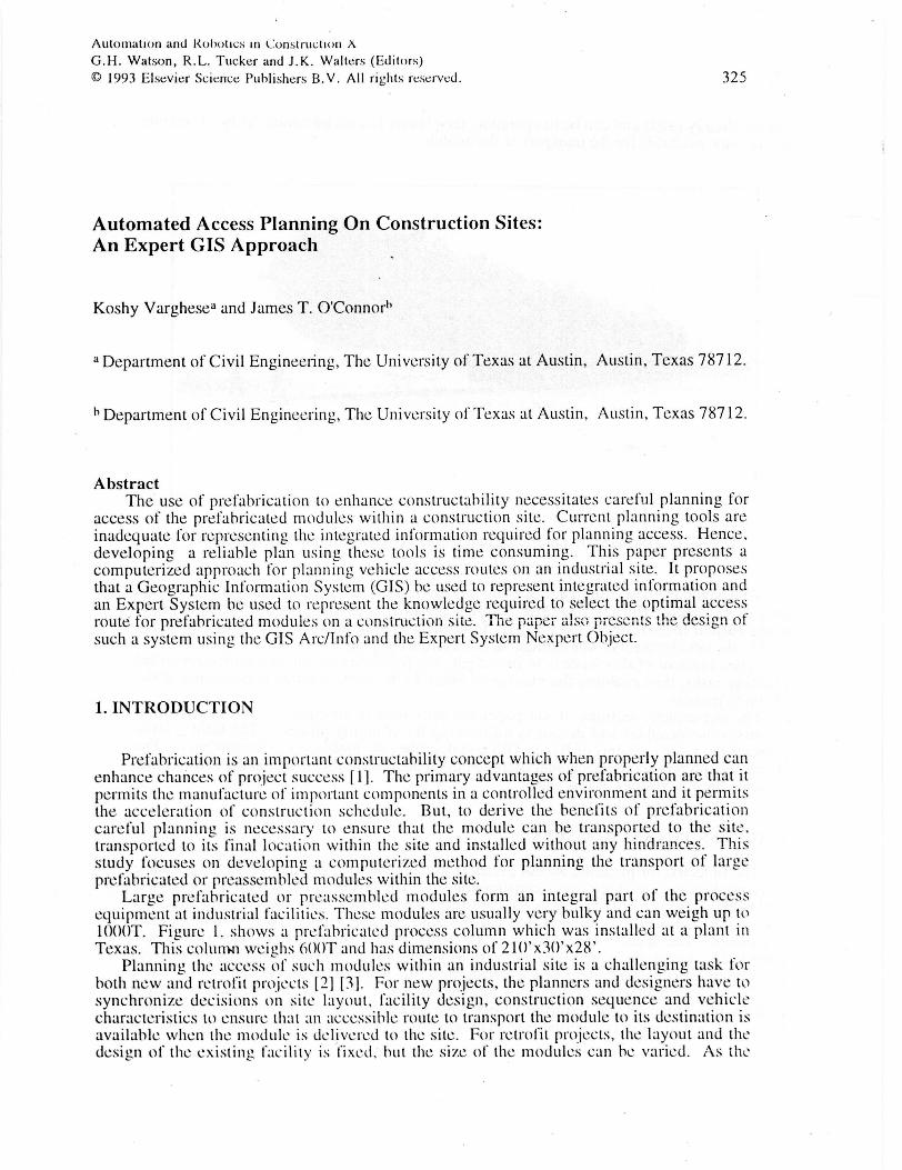
Large prefabricated or preassenlbled modules form an integral part of the processequipment at industrial facilities. These modules are usually very bulky and can weigh up to1000T. Figure 1. shows a prefabricated process column which was installed at a plant inTexas. This colunlal weighs 600T and has dimensions of 210'x3f1'x28'.
Planning the access of such modules within all industrial site is a challenging task forboth new and retrofit projects [2] (3]. For new projects, the planners and designers have tosynchronize decisions on site layout, facility design, construction sequence and vehiclecharacteristics to ensure that an accessible route to transport the module to its destination isavailable when the module is delivered to the site. For retrofit projects, the layout and thedesign of the existing facility is fixed, but the size of the modules can he varied. As the
326
facility already exists and can be in operation , the planner has to determine the most suitable
access route available for the transport of the module.
Figure 1. Transport of a prefabricated process column [Mammoet Transport]
To develop the best overall access plan , it is essential to investigate a number of alternate
project scenarios . But the repetitive , tedious and time consuming nature of the analysisusing current tools restricts the planners from investigating alternate scenarios . This can
lead to the development of non-optimal or even erroneous plans.The objective of this work is to investigate the feasibility of automating the repetitive
planning tasks, thus enabling the planner to focus on the more creative components of theplanning process.
The subsequent sections of the paper are presented in five parts . The next section
discusses the variables and decisions influencing the planning process. The third sectionpresents the basic concepts of Expert GIS and describes the tools used to implement it. Thefourth section presents a conceptual design of the route planning system and the final sectionpresents the conclusions of this paper.
2. ACCESS PLANNING ISSUES
The objective of planning access routes is to determine the optimal route for a vehicletraveling between two points on a construction site. The layout of the site for a new projectwill be dynamic as it will change as the construction progresses. The optimal route in such acase, can he defined as the route which satisfies both the access objective and overall projectobjectives. The access objective is to ensure that the transport activity has a minimumpotential of being obstructed from the various site features. The overall project objectivesare to minimize cost and duration while ensuring a safe work environment.
The project management decisions influencing access are: site layout, facility design,construction sequence and transport vehicle characteristics. These decisions can he variedand combined to generate alternate project scenarios. Each scenario is then be analyzed for
327
access requirements and the scenario which best satisfies the overall project objectives aswell as the access objectives is selected for execution.
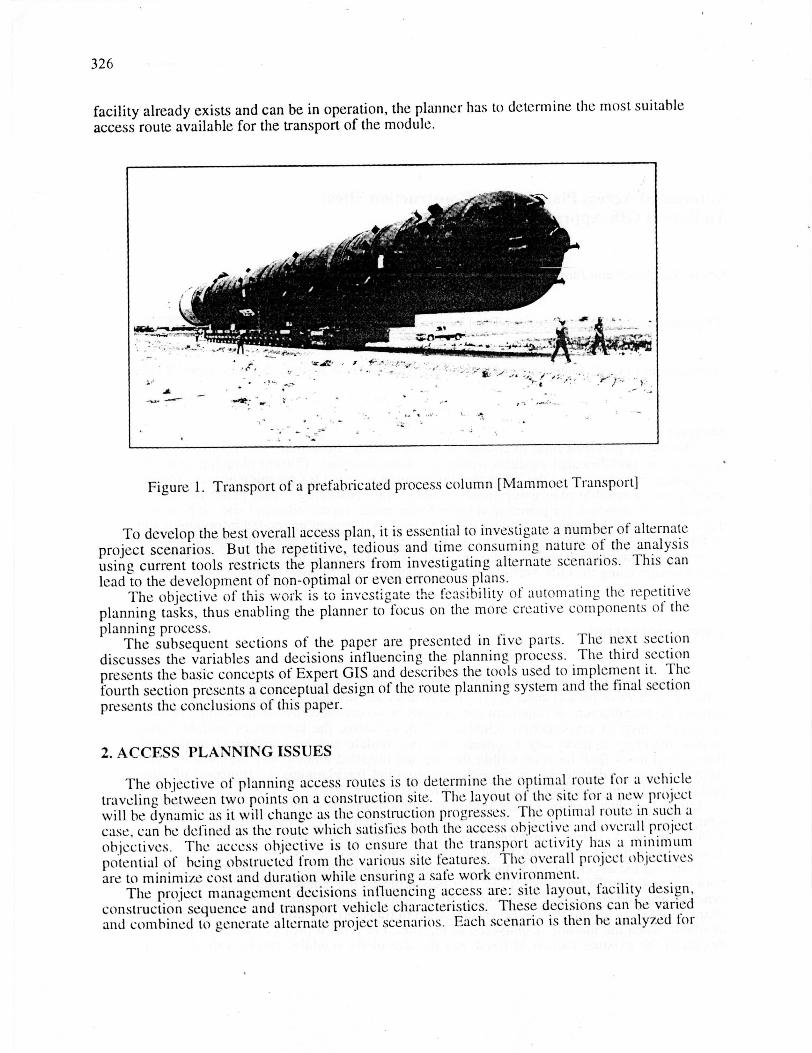
The human planner develops alternate scenarios based on his/her experience,imagination and creative thinking. To analyze a scenario the planner has to he aware of theproject features which influence access and the methods to determine the potential ofobstruction from these features. The common causes of obstruction on an industrial site areshown in Figure 2.
On Turns
Travel Restrictionson Site
Other RoadFactors AttributesI I
Obstacles Turn cannot bewithin turn negotiatedenvelope without going
off the road
OtherFactors
On Roads
Overhead Overstressed Steepobstructions undergrounds Gradeon road under road
RoadAttributes
High Insufficient InsufficientTraffic Capacity WidthIntensity
Figure 2. Causes of obstruction on an industrial site
The conventional tools used for analysis are: plot plans or solid models for representinglayout of the site, design in the form of drawings, bar charts for representing the schedule,and templates to represent the vehicle/module. To analyze a given scenario, the plannerhas to refer to the schedule documents and design drawings to determine the layout of thesite at the time of delivery and transform this information into a graphic representation.Next, the planner identifies potential access routes and using the template traces the vehiclepaths along the routes to determine if they are obstructed. In addition calculations have tobe performed to determine obstructions from features such as underground elements. If noaccessible routes are found, elements of the scenario have to be modified to create newscenario which is then reanalyzed. If multiple access routes are found the planner has tocompare the routes to select the best route. The comparison is based on the potential ofobstruction from the features along the route and the route with the least potential of beingobstructed is selected as the best route. Thus it can he seen that as the information is notintegrated, keeping track of the various pieces of data is a tedious task. Further, the iterativenature of the process requires the planner to repeat many of the mundane tasks, thusreducing the planning productivity.
The successful development of such a system which automates the tedious and repetitiveplanning tasks will increase the planners productivity. Although the generation of ascenario is a challenging task it is based primarily on the human creative capabilities and nocomputer methods to date can accurately model these capabilities. Further, there arenumerous other factors which influence the acceptability of a scenario. Thus, this workfocuses on providing the planner tools using which lie/she can use to: easily model alternatescenarios, represent the integrated information for each scenario and automatically analyzethe scenarios for the selection of the best access routes.
328
3. EXPERT GIS CONCEPTS AND TOOLS
An expert geographic information system combines the reasoning capability of an expertsystem and the spatial data representation and analysis capability of a geographicinformation system to form a powerful tool for spatial reasoning. The concept of expertGIS has been an active area of research, but only recent advances in hardware and softwarehas permitted its application of to real world problems.
Expert systems is a branch of artificial intelligence, an area in computer science dealingwith simulation of human intelligence. Expert systems attempt to simulate human reasoningby representing and processing knowledge. Knowledge can be represented using variousmethods such as predicate calculus, lists, frames, semantic nets and rules. Of all thesemethods, the use of rules is the most popular because its format is extremely flexible.
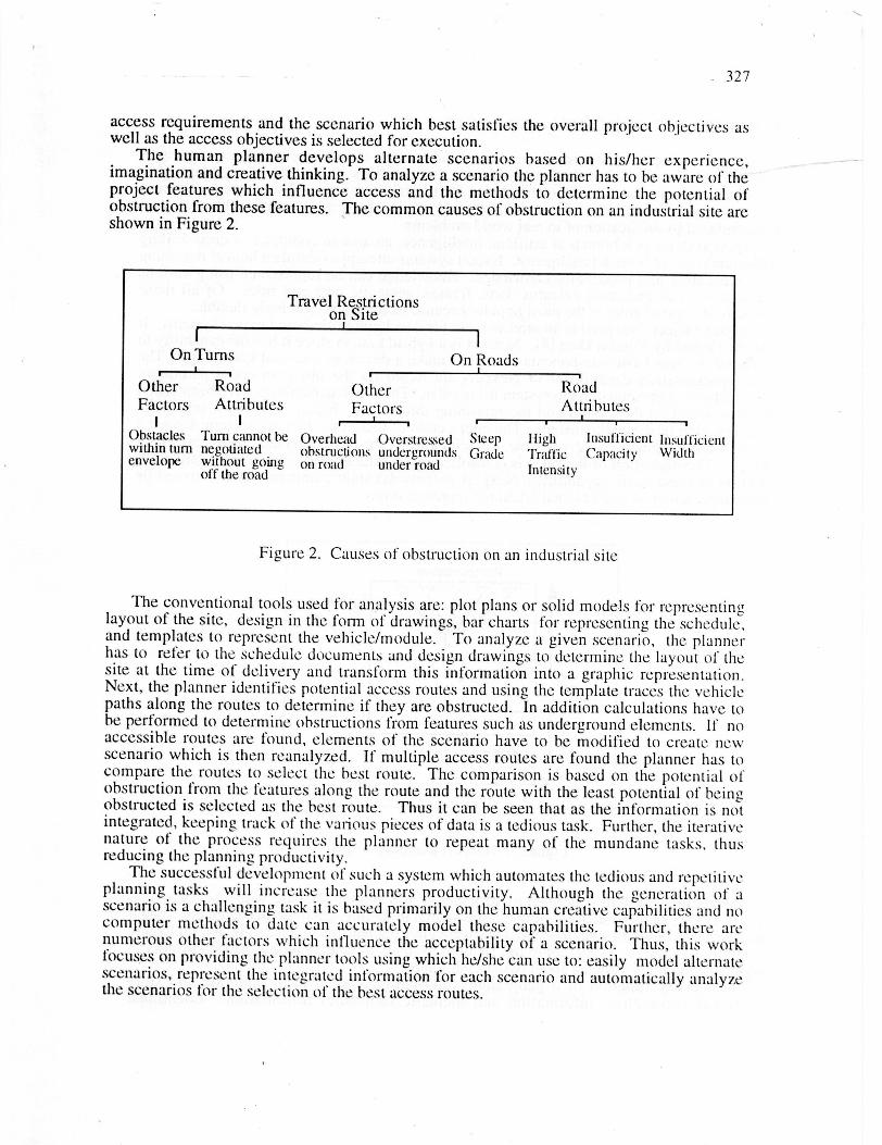
Nexpert Object (Nexpert) is an environment for developing rule-based expert systems. Itwas developed by Neuron Data [4]. Nexpert is a hybrid system since it has the capability torepresent the two basic components needed to make a decision: data and knowledge. Thedata representation capabilities of Nexpert are based on the object-oriented paradigm.Knowledge is represented in the system using rules. These two capabilities have been calledthe representation dimension and the reasoning dimension. Figure 3 shows a schematicrepresentation of these dimensions. The intersection of these two dimensions represents thefocus of the system at any given time, i.e. which rules are being executed based on whichobjects. The execution of the rules is controlled by an inference engine called Agenda. Inaddition to these basic capabilities, Nexpert permits dynamic communication between itsobject representation and external relational representations.
Figure 3. Nexpert Dimensions [4]
A geographic system is defined by Morehouse as a spatial database with a set of spatialoperators [5]. In its basic form, it integrates spatial modeling, database management, spatialanalysis and computer graphics into a software environment for representing and managinggeographic features. Geographic information systems as a technology, had its origins inautomated mapping systems about two decades ago.
The primary function of a geographic information system is to integrate and storelocational (geometric) information and thematic (attribute) information. Locational
329
information consists of data on the geographic location of points and lines, while thematicinformation consists of the non geometric attributes of the points and lines. For example,the locational information of a building can he the end coordinates of the lines which formits border, while the thematic information can pertain to its street address. Varioussophisticated tools have been built to manipulate, query and analyze the integratedinformation. These tools along with the tools required to represent the informationconstitute a geographic information system.
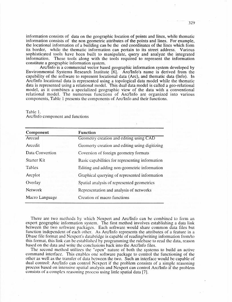
Arc/Info is a commercial vector based geographic information system developed byEnvironmental Systems Research Institute [6]. Arc/Info's name is derived from thecapability of the software to represent locational data (Arc), and thematic data (Info). InArc/Info locational data is represented using a topological data model while the thematicdata is represented using a relational model. This dual data model is called a geo-relationalmodel, as it combines a specialized geographic view of the data with a conventionalrelational model. The numerous functions of Arc/Info are organized into variouscomponents, Table 1 presents the components of Arc/Info and their functions.
Table 1.Arc/Info component and functions
ComponentArccad
Arcedit
Data Convertion
Starter Kit
Tables
Arcplot
Overlay
Network
Macro Language
Function
Geometry creation and editing using CAD
Geometty creation and editing using digitizing
Coversion of foreign geometry formats
Basic capabilities for representing information
Editing and adding non-geometric information
Graphical querying of represented information
Spatial analysis of represented geometries
Representation and analysis of networks
Creation of macro functions
There are two methods by which Nexpert and Arc/Info can he combined to form anexpert geographic information system. The first method involves establishing a data linkbetween the two software packages. Each software would share common data files butfunction independent of each other. As Arc/Info represents the attributes of a feature in aDbase file format and Nexpert's datahridge is capable of reading/writing information from/tothis format, this link can he established by programming the rulebase to read the data, reasonbased on the data and write the conclusions back into the Arc/Info files.
The second method utilizes the "open" nature of both the systems to build an activecommand interface. This enables one software package to control the functioning of theother as well as the transfer of data between the two. Such an interface would he capable ofdual control: Arc/Info can control Nexpert if the problem consists of a simple reasoningprocess based on intensive spatial analysis and Nexpert can control Arc/Info if the problemconsists of a complex reasoning process using little spatial data [7].
330
The human planner, when planning for access, uses many capabilities which can heemulated by an expert GIS. Therefore, a computerized system developed using an expertGIS approach can assist the planner by automating many of the route planning tasks.
4. SYSTEM DESIGN
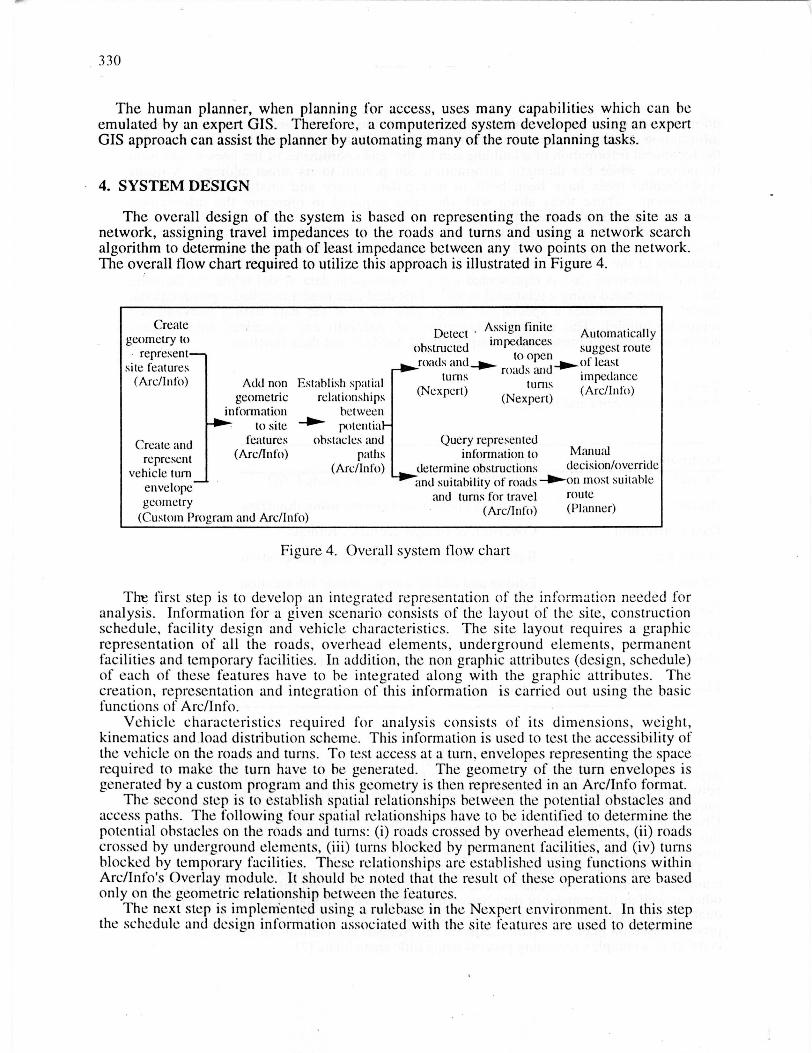
The overall design of the system is based on representing the roads on the site as anetwork, assigning travel impedances to the roads and turns and using a network searchalgorithm to determine the path of least impedance between any two points on the network.The overall flow chart required to utilize this approach is illustrated in Figure 4.
Create Assi n finiteg Automaticallygeometry to Detect • im edan esp csuggest routerepresent obstructed
to opensite features roads and_W.- roads and 40- of least
(Arc/Info) Add non Establish spatial turns impedanceturns
(Nexpert) (Arc/Info)geometric relationships (Nexpert)
information between-4110-to site potential
Create and features obstacles and Query represented
represent (Arc/Info) paths information to Manual
vehicle turn (Arc/Info) determine obstructions decision/override
envelope and suitability of roads --on most suitable
geometry and turns for travel route(Arc/Info) (Planner)
(Custom Pro-run and Arc/Info)
Figure 4. Overall system flow chart
ThL first step is to develop an integrated representation of the information needed foranalysis. Information for a given scenario consists of the layout of the site, constructionschedule, facility design and vehicle characteristics. The site layout requires a graphicrepresentation of all the roads, overhead elements, underground elements, permanentfacilities and temporary facilities. In addition, the non graphic attributes (design, schedule)of each of these features have to he integrated along with the graphic attributes. Thecreation, representation and integration of this information is carried out using the basicfunctions of Arc/Info.
Vehicle characteristics required for analysis consists of its dimensions, weight,kinematics and load distribution scheme. This information is used to test the accessibility ofthe vehicle on the roads and turns. To test access at a turn, envelopes representing the spacerequired to make the turn have to he generated. The geometry of the turn envelopes isgenerated by a custom program and this geometry is then represented in an Arc/Info format.
The second step is to establish spatial relationships between the potential obstacles andaccess paths. The following four spatial relationships have to he identified to determine thepotential obstacles on the roads and turns: (i) roads crossed by overhead elements, (ii) roadscrossed by underground elements, (iii) turns blocked by permanent facilities, and (iv) turnsblocked by temporary facilities. These relationships are established using functions withinArc/Info's Overlay module. It should he noted that the result of these operations are basedonly on the geometric relationship between the features.
The next step is implemented using a rulehase in the Nexpert environment. In this stepthe schedule and design information associated with the site features are used to determine
331
the roads and turns which are obstructed when the module is delivered to the site. Theseroads and turns are assigned an infinite impedance to indicate that the route cannot passthrough them. Each of the open roads and turns are then assigned a finite impedance basedon its characteristics and the importance assigned to each characteristic. The importanceassigned to each characteristic depends on the planners preferences and has to he establishedprior to the analysis and stored as relative weights in the rule base.
Functions to search the road network to select the route of least impedance can heimplemented using Arc/Info's Network component. In addition to selecting the route ofleast impedance, routines within Network can he.used to test user defined routes within thesite, generate alternate routes and display the routes.
In addition to the functions described above, provision of a querying capability willallow the system to act in a decision support mode. The querying capabilities of the systemare implemented using Arcplot. In the decision support mode the planner can query therepresented information, view the results graphically to reach a manual decision ifnecessary. For example, in response to a query to display the permanent facilities whichwill obstruct the vehicle at a turn, the system initially selects the set of permanent facilitiesinstalled before the specified travel day, and from this set those facilities which are withinthe vehicle's turn envelopes will he displayed in red.
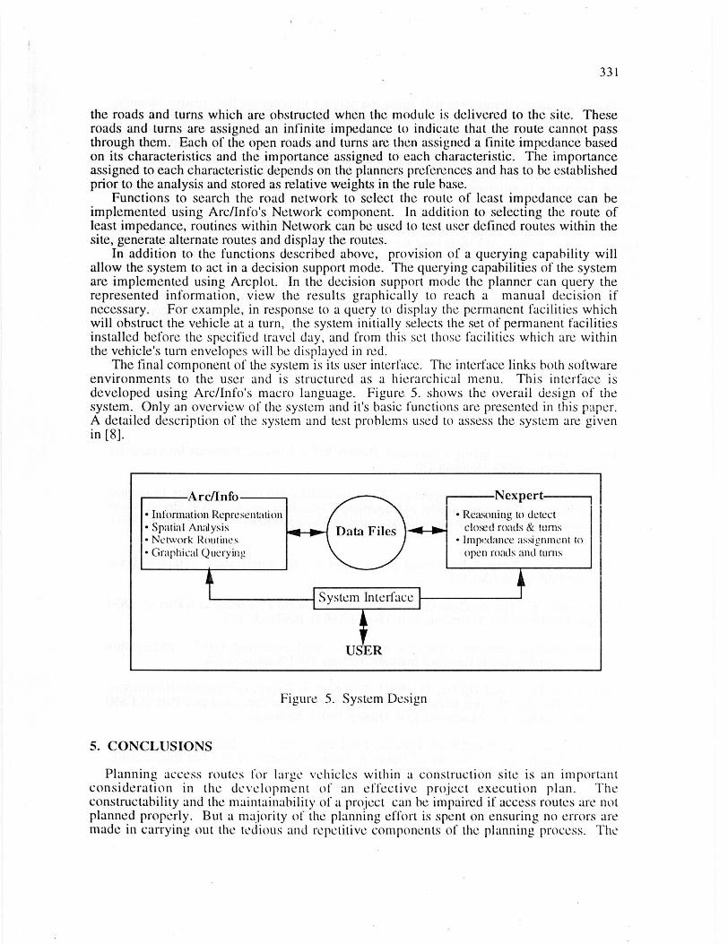
The final component of the system is its user interface. The interface links both softwareenvironments to the user and is structured as a hierarchical menu. This interface isdeveloped using Arc/Info's macro language. Figure 5. shows the overall design of thesystem. Only an overview of the system and it's basic functions are presented in this paper.A detailed description of the system and test problems used to assess the system are givenin [8].
Arc/Info
• Information Representa tion• Spatial Analysis• Network Routines• Graphical Querying
-46--job-
System Interface
USER
Figure 5. System Design
5. CONCLUSIONS
Nexpert
• Reasoning to detectclosed roads & turns
• Impedance assigiimGit toopen roads and turns
Planning access routes for large vehicles within a construction site is an importantconsideration in the development of an effective project execution plan. Theconstructahility and the maintainability of a project can be impaired if access routes are notplanned properly. But a majority of the planning effort is spent on ensuring no errors aremade in carrying out the tedious and repetitive components of the.. planning process. The
332
automation of these components will allow the planner to focus on the creative planningtasks thus enhancing the reliability of the plans and improving planning productivity.
This paper presented an approach to automate the tedious and repetitive tasks required toplan for access on a dynamic construction site. The expert GIS approach described in thiswork allows the creation of an integrated database which can represent both the graphicaland thematic information required for access planning. Using this representation as a base,custom programs, functions within Arc/Info and a rule base were developed to automate thenecessary planning tasks.
As constructahility analysis generally requires integrated representation of information,spatial analysis and reasoning, this technology can be applied to automate a variety ofplanning tasks. Further, the tools used for this work provide a suitable environment for thedevelopment of custom applications with a minimum investment in time and programmingeffort.
Future work in this area will focus on expanding the system to: (i) Model uncertainty andidentify areas of risk, (ii) Develop an example based pre-processor for quantifying plannerspreferences, and (iii) Represent strategies and knowledge required to modify a scenario tofacilitate access.
6. REFERENCES
[1] Construction Industry Institute. "Constructability concepts file". Publication 3-1,Construction Industry Institute, December 1987, The University of Texas at Austin,Austin TX.
[2] Gosch, Donnie Sr. Rigging Consultant, Brown & Root Braun, Personal Interview ByAuthor, August 1990, Houston TX
[3] American Society of Civil Engineers. "Constructability and Constructability Programs:White Paper." The Construction Management Committee of the ASCE ConstructionDivision. Journal of Construction Engineering and Management Vol. 17 (March 1991):p.67-89.
[4] Neuron Data "Nexpert Functional Description v 2.0." Publication, Neuron Data,October 1990, Palo-Alto, CA.
[5] Morehouse, S. "The Arc/Info GIS" A One Week Course Presented as a Part of ESRISummer Institute Ed. Maidment , D.R. (June 8 1991 ): Redlands, CA.
[6] Environmental Systems Research Institute. "Understanding GIS". PublicationEnvironmental Systems Research Institute, January 1991 Redlands, CA.
[7] Maidment, D. R. and Djokic, D.[1991] "Creating an Expert Geographic informationSystem: The Arc-Nexpert Interface." A One Week Course Presented as a Part of ESRISummer Institute Ed. Maidment, D.R. (June 8 1991): Redlands, CA.
[8] Varghese, K. "Automated Route Planning For Large Vehicles on Industrial ConstructionSites". Dissertation, University of Texas at Austin, Department of Civil Engineering.,August 1992.