Embed Size (px)
Citation preview
Automated Batting Cages
PT-4
OPERATION AND
TECHNICAL MANUAL
1
FOREWORD
IMPORTANT!
This Operation and Technical Manual provides the owners and maintenance personnel with information covering Safety Procedures, Maintenance Procedures, Operational
Procedures and Repair and Servicing of the Batting Cage equipment provided by
Automated Batting Cages Corp. Read this document carefully. This equipment system
contains several moving parts and has high voltage present which pose potential hazards
to maintenance and operational staff. Pitching baseball/softballs to batting range
customers also poses inherent risks to the batters. It is essential for operating a safe
batting range operation that the owner/operator have a complete understanding of this
manual. This manual must be used in conjunction with ABC training video tape to train
employees in the safe operation and servicing of the ABC batting range equipment system
and to minimize potential risks to the batting range customers.
ABC will update this manual from time to time. These updates and notices will be
mailed to the address that ABC has on record as your shipping address. Add these updates
and notices to your manual. Should any of these pages be lost or damaged, call ABC and
the pages will be replaced.
Please observe the following:
1). Keep this manual in the Maintenance Shop or Office during all
working hours.
2). Maintenance Personnel must review this manual before servicing any equipment.
Personal injury could result if maintenance personnel have not reviewed this manual.
3). All employees must review the “Standards for Batting Range Safety and
Operation” of this manual and the ABC training video tape.
4). When new procedures, standards, additions or other changes are made to this
manual, add them immediately to the manual.
Rev. ABC107
2
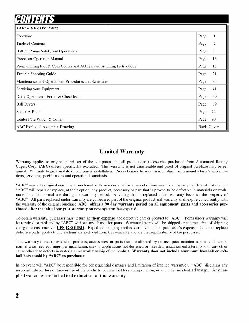
TABLE OF CONTENTS
Foreword Page 1
Table of Contents Page 2
Batting Range Safety and Operations Page 3
Processor Operation Manual Page 13
Programming Ball & Coin Counts and Abbreviated Auditing Instructions Page 15
Trouble Shooting Guide Page 21
Maintenance and Operational Procedures and Schedules Page 35
Servicing your Equipment Page 41
Daily Operational Forms & Checklists Page 59
Ball Dryers Page 69
Select-A-Pitch Page 74
Center Pole Winch & Collar Page 90
ABC Exploded Assembly Drawing Back Cover
Limited Warranty
Warranty applies to original purchaser of the equipment and all products or accessories purchased from Automated Batting
Cages, Corp. (ABC) unless specifically excluded. This warranty is not transferable and proof of original purchase may be re-
quired. Warranty begins on date of equipment installation. Products must be used in accordance with manufacturer’s specifica-
tions, servicing specifications and operational standards.
“ABC” warrants original equipment purchased with new systems for a period of one year from the original date of installation.
“ABC” will repair or replace, at their option, any product, accessory or part that is proven to be defective in materials or work-
manship under normal use during the warranty period. Anything that is replaced under warranty becomes the property of
“ABC”. All parts replaced under warranty are considered part of the original product and warranty shall expire concurrently with
the warranty of the original purchase. ABC offers a 90 day warranty period on all equipment, parts and accessories pur-
chased after the initial one year warranty on new systems has expired.
To obtain warranty, purchaser must return at their expense the defective part or product to “ABC”. Items under warranty will
be repaired or replaced by “ABC” without any charge for parts. Warranted items will be shipped or returned free of shipping
charges to customer via UPS GROUND. Expedited shipping methods are available at purchaser’s expense. Labor to replace
defective parts, products and systems are excluded from this warranty and are the responsibility of the purchaser.
This warranty does not extend to products, accessories, or parts that are affected by misuse, poor maintenance, acts of nature,
normal wear, neglect, improper installation, uses in applications not designed or intended, unauthorized alterations, or any other
cause other than defects in materials and workmanship of the product. Warranty does not include aluminum baseball or soft-
ball bats resold by “ABC” to purchaser.
In no event will “ABC” be responsible for consequential damages and limitation of implied warranties. “ABC” disclaims any
responsibility for loss of time or use of the products, commercial loss, transportation, or any other incidental damage. Any im-
plied warranties are limited to the duration of this warranty.
3
ABC STANDARDS FOR
BATTING RANGE SAFETY
& OPERATION
4
THESE BATTING RANGE DESIGN STANDARDS APPLY TO ALL OPERATORS/OWNERS OF
ABC COMMERCIAL BATTING RANGES. THESE DESIGN STANDARDS PROMOTE AND
ADVANCE SAFE BATTING RANGE OPERATIONS. THESE STANDARDS SHOULD BE
UNDERSTOOD AND FOLLOWED BY ALL OPERATORS/OWNERS OF COMMERCIAL
BATTING RANGES. ABC IS NOT RESPONSIBLE FOR THE COMPLIANCE OF THESE
DESIGN STANDARDS OR THE CONSEQUENCES OF NON-COMPLIANCE.
1. All batting areas (batting stalls) must be well defined and have marked areas where the batter must
stand.
2. All batting areas (batting stalls) must have a well defined and marked area where the balls will be
generally thrown. Batters boxes and home plates must be painted in batting area. Batting stalls must
be a hard surface, recommended materials include concrete, asphalt or wood.
3. All batting areas (batting stalls) must have a well defined and marked areas where batters are
excluded.
5. Sloping floors, to allow for balls to roll out of batting area, should be used in all batting range
operations.
6. Batting stalls must have adequate width to protect all batters and allow for batters swing width.
7. Batting stalls must have adequate depth to provide protection for batters and adjacent batters.
8. All batting stalls must have adequate lighting to provide complete visibility of pitched balls from
pitching machine to home plate.
9. All pitching systems must employ Warning Light(s) or other visible methods to signal the batters that
the pitching mechanism is ON and is capable of pitching a ball at any time.
10. Spectators must be adequately protected from contact with balls by netting and fencing systems. Balls
should never be able to escape the batting cage area.
11. Equipment system must provide for stop and starting operation while operating continually (“rental
play”).
12. All batting stall gates must employ self-closing mechanisms to prevent balls from exiting the batting
stalls.
13. All batting stalls which operate “dual-pitching mechanisms” (both baseball and softball pitching
mechanisms) must be adequately marked to inform batters of dual-use mechanisms.
14) All batting stalls must have protective padding on front of the vertical pipes to cushion the balls from
ricocheting back towards the batters.
5
THESE OPERATIONAL SAFETY STANDARDS APPLY TO ALL OPERATORS/OWNERS OF AN ABC
COMMERCIAL BASEBALL AND SOFTBALL BATTING RANGE. THEY ARE INTENDED TO INFORM THE
OPERATORS/OWNERS OF THE DANGERS AND RISKS ASSOCIATED IN THE OPERATION OF THE BATTING
RANGE AND TO PROMOTE THE SAFE OPERATION OF THE BATTING CAGES. ALL STANDARDS SHOULD
BE UNDERSTOOD AND FOLLOWED TO FACILITATE SAFETY IN THE BATTING CAGES. ABC IS NOT
RESPONSIBLE FOR THE COMPLIANCE OF THESE SAFETY STANDARDS OR THE CONSEQUENCES OF NON-
COMPLIANCE.
1 All batting stalls must adequately display a sign indicating how to operate the batting cage system. This sign must include
the following information: How to start the game, When balls will be pitched, And when the game is over.
2 All batting range operations must adequately display a sign indicating that pitching machines will throw both balls and
strikes.
3 All batting range operations must adequately display “Warning/Rules” sign's which include the following warnings and
rules:
*Batters MUST wear helmets with face mask protection at all times.
*If machines are pitching out of the strike zone immediately alert the attendant.
*Only one person in the batting cages at a time during play. No coaches allowed in cage during game play.
*No switch hitting during game.
*Batters must wear shoes. (No Baseball-Softball Cleats)
*No person under the influence of Drugs or Alcohol is permitted to use the batting cages.
*Report all accidents immediately.
*These pitching machines throw both balls and strikes. Players should “Be Alert” at all times.
*Do not stand on home plate.
*Watch for balls rolling under feet.
*No one under the age of 6 years old is permitted to use the batting cages.
*No one under the age of 16 is allowed to use cages throwing the effective speed of 70 - 75 Mph.
*An adult must accompany all batting cage players under the age of 10.
*Close gates at all times when entering or exiting the cages.
*No practice swings outside of cages unless in designated areas.
*During or after the game, do not pick up balls from ground. Do not throw balls back at pitching machines.
*CAUTION! Injuries could result from the use of this device. Users should assume the inherent risks of
batting baseballs and softballs. If users have any questions about the use of this device or the inherent risks associated with the
use of this device, ask the attendant before using the batting cages.
6
4. In addition to posting “Warning/Rules” signs, Operators/Owners of commercial batting ranges must comply with the
following operational safety standards:
*At least one trained attendant must be present at all times at the batting range to supervise the safe operation of the
batting range. Attendant must have reviewed and understood this manual and ABC training video tape.
*At least one trained attendant must be present at all times to supervise and/or conduct the maintenance program of the
batting range equipment/netting system. Attendant must have reviewed and understood this manual before performing any
maintenance or servicing.
*At least one attendant must be present at all times trained in the “Safety Rules” of the batting range. Attendant must
have reviewed and understood this manual and ABC training tape.
*Operator/Owner of the batting range must keep batting range equipment system maintained at all times to ABC’s
specifications. This manual details ABC’s specifications. It must be reviewed and understood in order to maintain the ABC
batting range equipment system. Keep this manual at the batting operation at all times for review. Refer to sections titled
“MAINTNENACE” and “SERVICING” for specifications.
*ABC maintenance and operational forms must be completed by owner/attendant and stored for later review to confirm
that maintenance and operational procedures have been followed. Refer to section titled “FORMS”.
*Attendant must check ball pitching accuracy of all pitching machines at least once per day. If the accuracy has
degraded, refer to the “TROUBLE SHOOTING GUIDE” section for proper adjustments.
*Operator/Owner must check daily, the condition of the balls. All balls showing signs of excessive wear, deformation,
cracks, breakage or when the dimples on the balls are less than 50% of there original depth. If any of these conditions exist,
remove balls from the batting range system immediately. Replace system with new balls. New balls cannot be mixed with old
balls!
*Operator/Owner must train all attendants in the safe operation of the batting range and insist that all attendants
maintain and promote a safe operation at all times. Training must include reviewing of this manual and ABC training video tape.
*Attendants or anyone inside of batting range must wear protective helmet with face guard at all times.
*Servicing of equipment system must be completed by a trained and qualified person having reviewed and understood
this manual and ABC training video tape.
5. Follow all other manufacturers’ operation and warnings when operating Center Pole Winch. All operators
of Center Pole Winch must review and understand all operating and safety instructions.
6. Owner/Operator should establish and implement a Safety Program similar to the program detailed in the following
“SAFETY PROGRAM FOR THE BATTING CAGES”
7. Balls remaining in hitting stalls must be “Cleared” by attendant before customer enters cage.
(*ALSO REFER TO SECTION TITLED “MAINTENANCE” FOR REGULARLY SCHEDULED
MAINTENACE and OPERATIONAL PROCEDURES).
7
THE FOREGOING IS A SAMPLE “SAFETY PROGRAM” FOR A COMMERCIAL BATTING
RANGE. PLEASE KEEP IN MIND THAT A SAFETY PROGRAM MAY INCLUDE OTHER
ELEMENTS THAN THOSE DETAILED HERE. ALL BATTING RANGE OPERATIONS
SHOULD HAVE A MANAGEMENT-SPONSORED COMPREHENSIVE “SAFETY PROGRAM”.
MANAGEMENT
It is essential that the management of the batting cage support the development and implementation of an
effective safety program. It is the responsibility of the management to commit to a safety program and to
communicate this commitment to all of management’s employees. The Safety Program must include
employee safety as well as guest safety and methods to carry out the program.
EMPLOYEE SAFETY
The safety of the employee must be the first priority of any safety program. Employee safety is mandated
by agencies including federal, state and local municipalities. Be certain that the employees understand the
risks that they are exposed to and how they can avoid these risks. Just as management must commit to the
safety program, employees must also be willing to accept their responsibility to the program.
EMPLOYEE SAFETY EXPOSURE
1. Hit by pitched ball
2. Hit by batted ball
3. Hit with bat outside of batting cage
4. Injury from contact with mechanical parts (i.e. wheels, belts, motors, electrical components, etc...)
5. Hit by ball in the “pit area”
6. Injuries while batting or giving instruction
7. Slip on floor
8. Fire or robbery
9. Horse play
10. Operating Center Pole Winch (raising and lowering netting)
EMPLOYEE RISK REDUCTION
1. Thoroughly train staff regarding all Safety/Warning policies (Warning Signs, etc)
2. Wear Batting Helmets with Face Guards at all times while in hitting area, including “pit area”
3. Sound a warning to batters (whistle, yell, etc...) when going to “pit area”
4. Use safety netting in pit to block holes in netting while working in area
5. Thoroughly train all staff on operation of all pitching machines and batting range equipment
systems. Have all staff review maintenance procedures with ABC Owner/Operator Manual
a. Train at initial hire
b. Re-train annually using ABC Operational and Technical Manual and ABC training video tape.
6. Thoroughly train staff of all Operating Standards relating to safety and operations
7. Turn off and unplug all electrical components when servicing equipment
8. Give instructions from outside of cages-Do Not enter cage when player is batting
9. Stop machines from pitching immediately when accidents occur or when rule enforcement is
necessary
10. Do not use batting cage after accident has occurred until all equipment has been checked for
proper operation
8
11. Train staff for all emergency policies
a. Police telephone number
b. Fire telephone number
c. Ambulance telephone number
12. All staff must have a “NO TOLERANCE RULE” for breaking any Safety Rules or Procedures
GUEST SAFETY
Guest safety is essential to the batting range success. All guest safety programs must begin with the
Employee safety program. Employees must be committed to this vital aspect of the business. The
employees will be the most responsible for any Guest Safety Program implemented by Management.
GUEST SAFETY EXPOSURE
1. Hit by pitched ball
2. Hit by batted ball
3. Hit by bat outside of cages
4. Player too young or inexperienced to use a batting cage
5. Batters not standing in Batters Box
6. Non-Contact injuries while batting (i.e. ankle, knee, etc...)
7. Players/Guest not complying with all posted Rules
8. Food poisoning
9. Fire
10. Slip and fall
11. Horseplay
GUEST RISK REDUCTION
1. List and display all SAFETY/WARNING SIGNS and RULES for quest to follow (see “Operation
Safety Standards”)
2. Have all employees understand these SAFETY/WARNING SIGNS and RULES and ENFORCE
THESE RULES! (see “Operational Safety Standards”)
3. At least ONE batting range EMPLOYEE MUST BE ON DUTY AT ALL TIMES DURING
CAGE OPERATION!
4. Pitching Machines, Warning Lights and related Feeding Systems must be adjusted and
maintained at all times and must be in good working order at all times while batting cage is
available for play.
5. Signs must be posted stating type of cage (baseball or softball) and speeds of pitch in each cage
6. Regular cleaning of floor/concrete to prevent slipping and to keep balls clean
7. All netting and protective fencing must be repaired, maintained and replaced when necessary
8. Inspect, clean and replace worn balls regularly
9. Follow all local health and safety codes
10. Employee must stop balls from pitching immediately when any accident occurs. Attend to guest
immediately (refer to Management’s Emergency Procedures). Do not allow batting in the
batting cage where accident occurred until all equipment has been checked for proper
operating condition. File Incident Report.
9
11. Completely train and re-train all employees about safety risks of your guests and themselves!
12. INSIST THAT EMPLOYEES HAVE ALL GUESTS FOLLOW THE POSTED RULES!
EMPLOYEES MUST HAVE A “ZERO TOLERANCE RULE” FOR GUEST BREAKING POSTED RULES!
13. EMPLOYEES MUST TAKE IMMEDIATE STEPS (stop pitching machines and remove
batter from cage) TO MINIMIZE SAFETY RISKS TO GUEST WHEN RISK ARE
APPARENT!
FIRE PROTECTION
Fire protection should always be a part of Management’s Safety Program. Consult with local fire
authorities about their requirements. Be certain that employees have knowledge about the fire protection
available at the batting cage.
FIRST AID
Management should have four basic areas of responsibility for First Aid.
1. Employee First Aid - Check with local agencies about First Aid Kits and your responsibility for
Employee First Aid
2. First Aid to guests.
a. Emergency First Aid - Have Emergency plan documented for employees to follow
b. Courtesy First Aid - Have Band-Aids, ice, etc...)
3. Record Keeping and Reporting - It is essential that all First Aid (either employee or guest related)
be documented and maintained for future reference
4. Injury Claims defense - Providing first aid and documenting the type and extent of all injuries and
how the injury occurred is necessary for any Injury Claim Defense
INSPECTION
A Safety Program should address the need for inspections. These inspections should be focused in at least
four areas:
1. Inspection of employees work area
2. Inspections to insure guest safety–see Regularly scheduled Maintenance and Operational
Procedures in “Maintenance” section.
3. Inspections for housekeeping and fire protection
4. Required inspections for Federal, State and Local Requirements.
ACCIDENT INVESTIGATION
In order to reduce accidents from occurring, a preventive program must be in place. Recognizing potential
risks and taking the appropriate steps to minimize or eliminate these risks is critical. All accidents must be
investigated and documented, even if injuries have not resulted from the accident. Communicating these
accidents should be a regular occurrence within the Safety Program.
SAFETY TRAINING
Safety training should not be confused with Job Training. Safety training should be conducted singularly
(continued next page)
10
and considered a separate responsibility of the employee. Safety Training should be conducted when the
employee is first hired and should be reviewed at least once a year.
RECORD KEEPING
Record Keeping for the Safety Program should include several records including; Employee Injury Reports,
Guest Injury Reports, Inspection/Maintenance Reports, documented Safety Program Training and reviews
and “Accident Investigation” meetings. (Refer to section “Daily Operational Forms & Checklists”).
BATTING RANGE EQUIPMENT MAINTENANCE
Equipment maintenance should only be performed by qualified persons with a full understanding of the
equipment and how it operates. It is also very important that the person maintaining the equipment
understands about the batting range operation and risks involved with repairing and maintaining the system.
All daily, weekly, monthly and other periodic maintenance should be conducted on the pitching machine
equipment and the related equipment. Refer to the section titles “MAINTENANCE” in the “ABC Owner/
Operators Manual” for specific maintenance and operational procedures. Document all maintenance and
operational procedures and file for future reference.
COMMUNICATIONS
The Safety Program must be communicated clearly and understood by every person involved in it’s
implementation. Communication techniques should include written material along with on-site instructions
and directions. All training sessions should be documented and filed for future reference.
HOUSEKEEPING
Safety Program should include a Housekeeping element and all staff should understand the necessity of
cleanliness.
EMERGENCY PROCEDURES Management must detail Emergency Procedures which would be followed in the event of any emergency.
These emergencies will include NATURAL DISASTERS (wind, rain, earthquake, etc...), ACCIDENTS
(injuries) and MAN-MADE DISASTERS (bomb threats, structural, power outages, etc...).
11
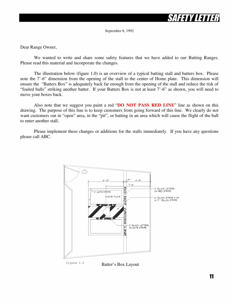
Batter’s Box Layout
September 8, 1992
Dear Range Owner,
We wanted to write and share some safety features that we have added to our Batting Ranges.
Please read this material and incorporate the changes.
The illustration below (figure 1.0) is an overview of a typical batting stall and batters box. Please
note the 7’-6” dimension from the opening of the stall to the center of Home plate. This dimension will
ensure the “Batters Box” is adequately back far enough from the opening of the stall and reduce the risk of
“fouled balls” striking another batter. If your Batters Box is not at least 7’-6” as shown, you will need to
move your boxes back.
Also note that we suggest you paint a red “DO NOT PASS RED LINE” line as shown on this drawing. The purpose of this line is to keep customers from going forward of this line. We clearly do not
want customers out in “open” area, in the “pit”, or batting in an area which will cause the flight of the ball
to enter another stall.
Please implement these changes or additions for the stalls immediately. If you have any questions
please call ABC.
figure 1.0
12
IMPORTANT INFORMATION
WINCH & CENTER POLE COLLAR STOPS
IN ALL CASES, THE CENTER POLE WINCH AND COLLAR AS-
SEMBLY MUST ONLY BE USED WITH “CENTER POLE COLLAR
STOPS” WELDED IN PLACE ON THE CENTER POLE. THESE STOPS
SHOULD HAVE BEEN WELDED ONTO THE CENTER POLE AT THE
INITIAL CONSTRUCTION PHASE. THEY WERE (AND ARE) IL-
LUSTRATED ON THE ORIGINAL “ABC” CONSTRUCTION BLUE
PRINTS AND ILLUSTRATED IN THE ENCLOSED DRAWING. “ABC”
WILL PROVIDE THESE COLLAR STOPS AT NO CHARGE. THESE
STOPS WORK AS AN EMERGENCY COLLAR STOP. WINCHES
SHOULD NEVER BE USED WITHOUT THESE COLLAR STOPS! IF
THESE STOPS ARE NOT IN PLACE, DO NOT OPERATE THE WINCH.
NOTICE!
“ABC” HAS BEEN OFFERING TO SELL CENTER POLE WINCHES
AND CABLES THAT WE BELIEVE ARE OF SUFFICIENT QUALITY
AND OF SUFFICIENT LIFTING CAPABILITY. HOWEVER,
FAILURES CAN OCCUR WHICH MAY RESULT IN THE COLLAR
FALLING UNCONTROLLABLY. WITHOUT CENTER POLE STOPS,
SERIOUS INJURIES MAY RESULT!
IF YOU HAVE ANY QUESTIONS REGARDING THE USE, SAFETY
AND OPERATION OF THESE WINCHES OR CABLES, CONTACT
YOUR LOCAL OSHA INSPECTOR AND/OR LOCAL ENGINEER TO
SATISFY YOUR CONCERNS. REFER TO PAGES 115-137 FOR
DRAWINGS, CONNECTIONS DETAILS AND LOAD RATINGS.
13
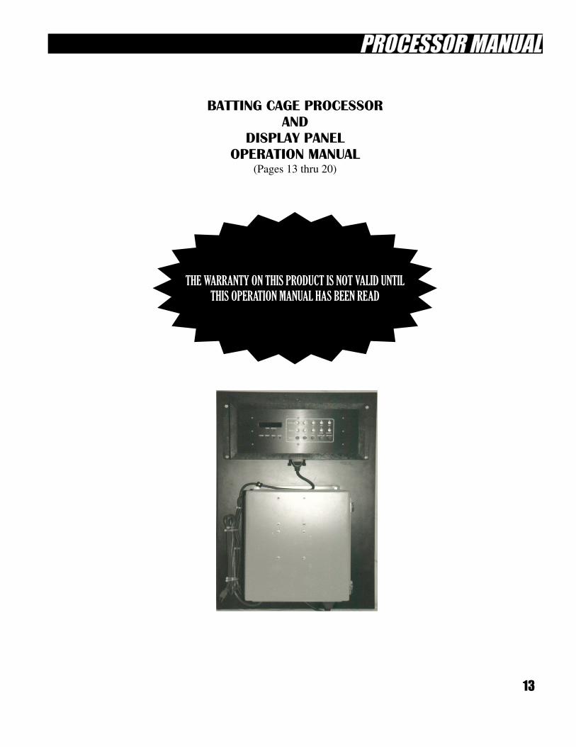
BATTING CAGE PROCESSOR
AND
DISPLAY PANEL
OPERATION MANUAL
(Pages 13 thru 20)
THE WARRANTY ON THIS PRODUCT IS NOT VALID UNTIL
THIS OPERATION MANUAL HAS BEEN READ
14
TABLE OF CONTENTS (PROCESSOR MANUAL)
Processor Features page 14
Wiring Instructions page 15
Programming Ball and Coin counts page 15
Operating Instructions page 16
Displaying Amounts in Counters page 17
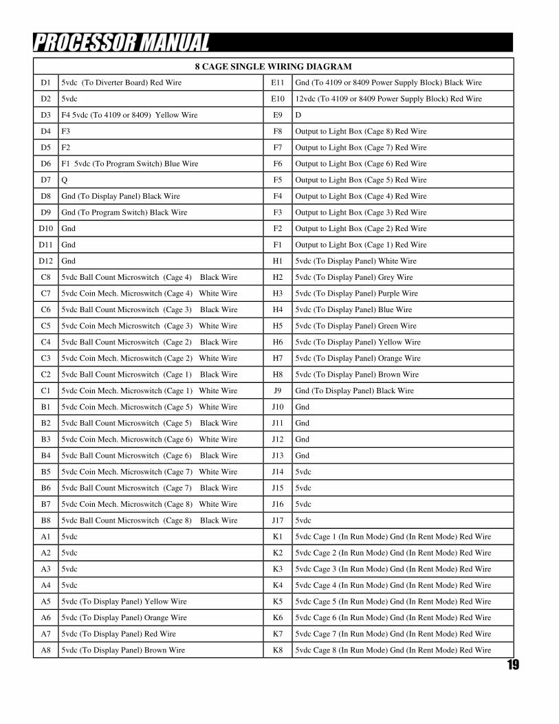
page 19 8 Cage Single Wiring Diagram
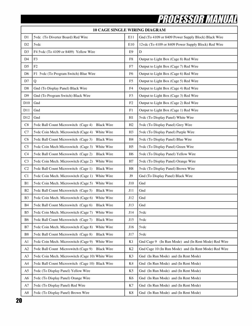
10 Cage Single Wiring Diagram Page 20
Operation of Manual Switch Page 16
Auditing Usage Page 18
Programming 8 or 10 Cage Operation Page 14
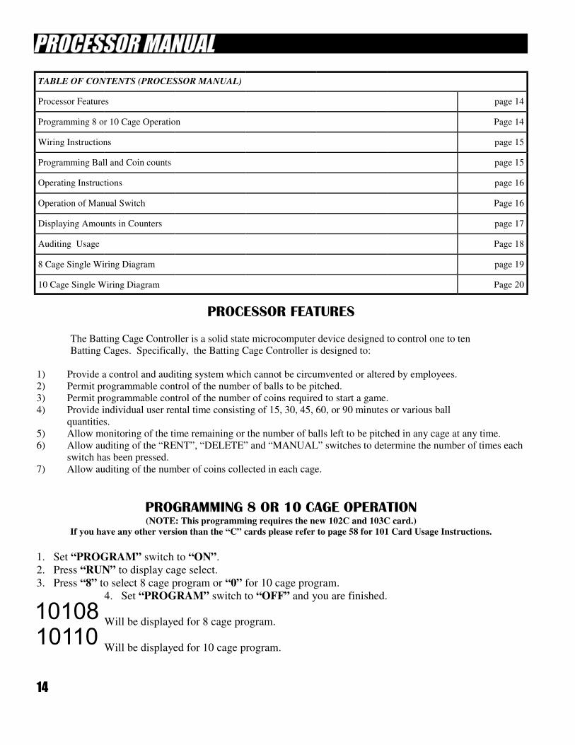
PROCESSOR FEATURES
The Batting Cage Controller is a solid state microcomputer device designed to control one to ten
Batting Cages. Specifically, the Batting Cage Controller is designed to:
1) Provide a control and auditing system which cannot be circumvented or altered by employees.
2) Permit programmable control of the number of balls to be pitched.
3) Permit programmable control of the number of coins required to start a game.
4) Provide individual user rental time consisting of 15, 30, 45, 60, or 90 minutes or various ball
quantities.
5) Allow monitoring of the time remaining or the number of balls left to be pitched in any cage at any time.
6) Allow auditing of the “RENT”, “DELETE” and “MANUAL” switches to determine the number of times each
switch has been pressed.
7) Allow auditing of the number of coins collected in each cage.
PROGRAMMING 8 OR 10 CAGE OPERATION (NOTE: This programming requires the new 102C and 103C card.)
If you have any other version than the “C” cards please refer to page 58 for 101 Card Usage Instructions.
1. Set “PROGRAM” switch to “ON”.
2. Press “RUN” to display cage select.
3. Press “8” to select 8 cage program or “0” for 10 cage program.
4. Set “PROGRAM” switch to “OFF” and you are finished.
Will be displayed for 8 cage program.
Will be displayed for 10 cage program.
15
WIRING INSTRUCTIONS
1) Using a 3-conductor shielded cable, the ball counter microswitches are connected to the appropriate
inputs in the control box. (See Appendix A for a complete wire list.) The common of the
microswitch is connected to the common line. Shield of cable must not be connected to case ground
at machine, but must be connected to common or ground at the control box.
2) The outputs in the control box are connected to the “A” or “B” inputs of the light box controller.
3) The common of the cable MUST NOT be grounded at the machine, but at the common of the
control box.
NOTE: COMMON IS NOT GROUND EXCEPT IN THE CONTROL BOX
1) Using a 2-conductor shielded cable, the normally open contacts of the microswitches on the coin
mechanisms are connected to the coin inputs of the control box. (See Appendix A for a complete
wire list.) The common of the microswitch is connected to the common line.
PROGRAMMING BALL AND COIN COUNTS
The Batting Cage Controller is designed so that changes can easily be made in either the ball count
or the coin count, or in both of these counts if desired. To change the ball or coin count follow these
steps:
1) Flip “PROGRAM” switch in the control box to “ON”.
2) Press “RENT” to display existing ball count, or “CAGE” to display existing coin count.
3) If desired count is less than the existing count, press switch #4 to clear counter. Then press switches
1, 2, and 3 in the proper order as described below. (see note)
4) If desired count is greater than existing count, use switches 1, 2, and 3 as described below (see note)
6) When finished, flip “PROGRAM” switch to “OFF”.
NOTE: Switches 1, 2, 3, and 4 are used to change the ball and coin counts stored in the memory of the controller.
1) Switch #1 increases the count by one.
2) Switch #2 increases the count by five.
3) Switch #3 increases the count by ten.
4) Switch #4 clears the counter completely.
(Continued on page 16)
16
(Continued from page 15)
The maximum ball or coin count is 255. Ant attempt to program the count to exceed this maximum
will cause the counter to clear completely.
Although the “RENTAL TIME” and “RENTAL BALLS” cannot be changed with the above
method, the Phenix Company can change these amounts if desired and provide a new front panel.
OPERATING INSTRUCTIONS
After the ball and coin counts have been programmed, you’re ready to operate.
1) Press the “RUN” switch. This puts the panel in the normal run mode.
2) Press the “CAGE” switch, followed by the switch for the cage you wish to operate. (cage numbers are
above switches.)
3) Press the “RENT” switch, followed by the switch for the amount of time or number of balls desired.
(Numbers below switches).
The machine will now operate. Should you want to stop the operation of any machine, just press
the switch for that particular cage, followed by the “DELETE” switch.
OPERATION OF MANUAL SWITCH
The “MANL” switch can turn on any batting cage. To operate a batting cage of your choice, follow
these steps:
1) Press the switch for the cage you want to operate.
2) Press the “RENT” switch, then “MANL”.
The quantity displayed on the counter will decrease as each ball is pitched, and the machine will
stop pitching after the set number of balls. You may also stop the machine by pressing the “DELETE”
switch.
(Continued on page 17)
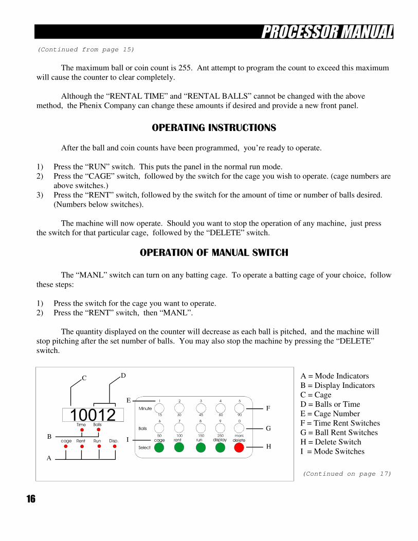
C D A = Mode Indicators
B = Display Indicators
C = Cage
D = Balls or Time
E = Cage Number
F = Time Rent Switches
G = Ball Rent Switches
H = Delete Switch
I = Mode Switches A
B
G
F
H
E
I
17
(Continued from page 16)
TO DISPLAY AMOUNTS IN COUNTERS
The Batting Cage Controller is designed to allow you to audit the following functions.
1) The number of coins collected in each cage.
2) The number of times each quantity of rental time or balls has been activated.
3) The number of times the “DELETE” and “MANUAL” switches have been pressed.
In order to audit the functions described above, follow these steps:
1) Press “DISPLAY”. This puts the panel in
the display mode.
2) To audit the number of coins collected in a particular cage, press “CAGE”, followed by the switch
for the cage you want to check.
3) To audit the number of rentals, press “RENT”, followed by the switch for the amount of rental time
or balls you want to check.
EXAMPLE: 10009
In the amount displayed above, the 1 represents the number of the cage being audited. The 9
represents the number of coins collected in cage number 1.
4) Press “RUN” to exit the display mode.
1) Press “DISPLAY” switch, followed by “RENT”, and then “MANL”.
2) Press “RUN” to exit the display mode.
1) Press “DISPLAY”. This puts the panel in the display mode.
2) Press “DELETE”.
3) Press “RUN” to exit the display mode.
18
AUDITING USAGE
The Batting Cage Controller is designed to allow you to audit the following functions:
1. The number of coins collected in each cage.
2. The number of times each quantity of rental time or balls has been activated
3. The number of times the “DELETE” switch has been pressed.
4. The number of times the “MANUAL” switch has been pressed.
In order to audit the functions described above, follow these steps:
1. COIN COUNT:
• Press “DISPLAY” button, this puts the panel in the display mode.
• To audit the number of coins collected in a particular cage, press
the “CAGE” button, followed by the switch for the cage you want
to check. EXAMPLE: To display the number of coins collected in
cage #1.
Press “DISPLAY”
Press “CAGE”
Press “1”
Press “RUN” to exit the display mode.
2. RENT & BALL COUNTS:
• Press “RENT” button, followed by the switch for the amount of rental
time or balls you want to check. EXAMPLE: To display the number of
times the 45min switch has been pressed.
Press “DISPLAY”
Press “RENT”
Press “45”
Press “RUN” to exit the display mode.
3. DELETE COUNT:
• Press “DISPLAY” button, this puts the panel in the display mode.
• Press “DELETE”.
• Press “RUN” to exit the display mode.
4. MANUAL COUNT:
• Press “DISPLAY” button, this puts the panel in the display mode.
• Press “MANUAL”.
• Press “RUN” to exit the display mode.
19
D1 5vdc (To Diverter Board) Red Wire E11 Gnd (To 4109 or 8409 Power Supply Block) Black Wire
D2 5vdc E10 12vdc (To 4109 or 8409 Power Supply Block) Red Wire
D3 F4 5vdc (To 4109 or 8409) Yellow Wire E9 D
D4 F3 F8 Output to Light Box (Cage 8) Red Wire
D5 F2 F7 Output to Light Box (Cage 7) Red Wire
D6 F1 5vdc (To Program Switch) Blue Wire F6 Output to Light Box (Cage 6) Red Wire
D7 Q F5 Output to Light Box (Cage 5) Red Wire
D8 Gnd (To Display Panel) Black Wire F4 Output to Light Box (Cage 4) Red Wire
D9 Gnd (To Program Switch) Black Wire F3 Output to Light Box (Cage 3) Red Wire
D10 Gnd F2 Output to Light Box (Cage 2) Red Wire
D11 Gnd F1 Output to Light Box (Cage 1) Red Wire
D12 Gnd H1 5vdc (To Display Panel) White Wire
C8 5vdc Ball Count Microswitch (Cage 4) Black Wire H2 5vdc (To Display Panel) Grey Wire
C7 5vdc Coin Mech. Microswitch (Cage 4) White Wire H3 5vdc (To Display Panel) Purple Wire
C6 5vdc Ball Count Microswitch (Cage 3) Black Wire H4 5vdc (To Display Panel) Blue Wire
C5 5vdc Coin Mech Microswitch (Cage 3) White Wire H5 5vdc (To Display Panel) Green Wire
C4 5vdc Ball Count Microswitch (Cage 2) Black Wire H6 5vdc (To Display Panel) Yellow Wire
C3 5vdc Coin Mech. Microswitch (Cage 2) White Wire H7 5vdc (To Display Panel) Orange Wire
C2 5vdc Ball Count Microswitch (Cage 1) Black Wire H8 5vdc (To Display Panel) Brown Wire
C1 5vdc Coin Mech. Microswitch (Cage 1) White Wire J9 Gnd (To Display Panel) Black Wire
B1 5vdc Coin Mech. Microswitch (Cage 5) White Wire J10 Gnd
B2 5vdc Ball Count Microswitch (Cage 5) Black Wire J11 Gnd
B3 5vdc Coin Mech. Microswitch (Cage 6) White Wire J12 Gnd
B4 5vdc Ball Count Microswitch (Cage 6) Black Wire J13 Gnd
B5 5vdc Coin Mech. Microswitch (Cage 7) White Wire J14 5vdc
B6 5vdc Ball Count Microswitch (Cage 7) Black Wire J15 5vdc
B7 5vdc Coin Mech. Microswitch (Cage 8) White Wire J16 5vdc
B8 5vdc Ball Count Microswitch (Cage 8) Black Wire J17 5vdc
A1 5vdc K1 5vdc Cage 1 (In Run Mode) Gnd (In Rent Mode) Red Wire
A2 5vdc K2 5vdc Cage 2 (In Run Mode) Gnd (In Rent Mode) Red Wire
A3 5vdc K3 5vdc Cage 3 (In Run Mode) Gnd (In Rent Mode) Red Wire
A4 5vdc K4 5vdc Cage 4 (In Run Mode) Gnd (In Rent Mode) Red Wire
A5 5vdc (To Display Panel) Yellow Wire K5 5vdc Cage 5 (In Run Mode) Gnd (In Rent Mode) Red Wire
A6 5vdc (To Display Panel) Orange Wire K6 5vdc Cage 6 (In Run Mode) Gnd (In Rent Mode) Red Wire
A7 5vdc (To Display Panel) Red Wire K7 5vdc Cage 7 (In Run Mode) Gnd (In Rent Mode) Red Wire
8 CAGE SINGLE WIRING DIAGRAM
A8 5vdc (To Display Panel) Brown Wire K8 5vdc Cage 8 (In Run Mode) Gnd (In Rent Mode) Red Wire
20
D1 5vdc (To Diverter Board) Red Wire E11 Gnd (To 4109 or 8409 Power Supply Block) Black Wire
D2 5vdc E10 12vdc (To 4109 or 8409 Power Supply Block) Red Wire
D3 F4 5vdc (To 4109 or 8409) Yellow Wire E9 D
D4 F3 F8 Output to Light Box (Cage 8) Red Wire
D5 F2 F7 Output to Light Box (Cage 7) Red Wire
D6 F1 5vdc (To Program Switch) Blue Wire F6 Output to Light Box (Cage 6) Red Wire
D7 Q F5 Output to Light Box (Cage 5) Red Wire
D8 Gnd (To Display Panel) Black Wire F4 Output to Light Box (Cage 4) Red Wire
D9 Gnd (To Program Switch) Black Wire F3 Output to Light Box (Cage 3) Red Wire
D10 Gnd F2 Output to Light Box (Cage 2) Red Wire
D11 Gnd F1 Output to Light Box (Cage 1) Red Wire
D12 Gnd H1 5vdc (To Display Panel) White Wire
C8 5vdc Ball Count Microswitch (Cage 4) Black Wire H2 5vdc (To Display Panel) Grey Wire
C7 5vdc Coin Mech. Microswitch (Cage 4) White Wire H3 5vdc (To Display Panel) Purple Wire
C6 5vdc Ball Count Microswitch (Cage 3) Black Wire H4 5vdc (To Display Panel) Blue Wire
C5 5vdc Coin Mech Microswitch (Cage 3) White Wire H5 5vdc (To Display Panel) Green Wire
C4 5vdc Ball Count Microswitch (Cage 2) Black Wire H6 5vdc (To Display Panel) Yellow Wire
C3 5vdc Coin Mech. Microswitch (Cage 2) White Wire H7 5vdc (To Display Panel) Orange Wire
C2 5vdc Ball Count Microswitch (Cage 1) Black Wire H8 5vdc (To Display Panel) Brown Wire
C1 5vdc Coin Mech. Microswitch (Cage 1) White Wire J9 Gnd (To Display Panel) Black Wire
B1 5vdc Coin Mech. Microswitch (Cage 5) White Wire J10 Gnd
B2 5vdc Ball Count Microswitch (Cage 5) Black Wire J11 Gnd
B3 5vdc Coin Mech. Microswitch (Cage 6) White Wire J12 Gnd
B4 5vdc Ball Count Microswitch (Cage 6) Black Wire J13 Gnd
B5 5vdc Coin Mech. Microswitch (Cage 7) White Wire J14 5vdc
B6 5vdc Ball Count Microswitch (Cage 7) Black Wire J15 5vdc
B7 5vdc Coin Mech. Microswitch (Cage 8) White Wire J16 5vdc
B8 5vdc Ball Count Microswitch (Cage 8) Black Wire J17 5vdc
A1 5vdc Coin Mech. Microswitch (Cage 9) White Wire K1 Gnd Cage 9 (In Run Mode) and (In Rent Mode) Red Wire
A2 5vdc Ball Count Microswitch (Cage 9) Black Wire K2 Gnd Cage 10 (In Run Mode) and (In Rent Mode) Red Wire
A3 5vdc Coin Mech. Microswitch (Cage 10) White Wire K3 Gnd (In Run Mode) and (In Rent Mode)
A4 5vdc Ball Count Microswitch (Cage 10) Black Wire K4 Gnd (In Run Mode) and (In Rent Mode)
A5 5vdc (To Display Panel) Yellow Wire K5 Gnd (In Run Mode) and (In Rent Mode)
A6 5vdc (To Display Panel) Orange Wire K6 Gnd (In Run Mode) and (In Rent Mode)
A7 5vdc (To Display Panel) Red Wire K7 Gnd (In Run Mode) and (In Rent Mode)
10 CAGE SINGLE WIRING DIAGRAM
A8 5vdc (To Display Panel) Brown Wire K8 Gnd (In Run Mode) and (In Rent Mode)
21
TROUBLE SHOOTING GUIDE
FOR ABC’S
BATTING RANGE SYSTEM
Pages 21 thru 34
22
CAUTION! EMPLOYEES SHOULD ALWAYS WEAR A BATTING HELMET WITH FACE
GUARD AND SOUND A WARNING FOR BATTERS TO LEAVE BATTING STALLS DURING
MAINTENANCE OF EQUIPMENT
THIS EQUIPMENT SYSTEM HAS SEVERAL MOVING PARTS AND HIGH VOLTAGE PRESENT WHICH
POSE POTENTIAL DANGER TO ANY PERSON SERVICNG OR MAINTAINING IT. BEFORE SERVICING OR
MAINTAINING EQUIPMENT SYSTEM, YOU MUST REVIEW “MAINTENANCE” SECTION OF THIS
MANUAL. SERIOUS INJURIES COULD RESULT IF NOT REVIEWED, UNDERSTOOD AND FOLLOWED!
This introduction is an explanation of how ABC’s Batting Range System works from the
initiation of the game to the completion of the game.
A. MICROPROCESSOR
The microprocessor, or master control panel, is the brain of your batting range. The logic, or
“thinking abilities” of the microprocessor will determine when the cages begin operation and the type of
game to be played, (i.e. coin activated game, manually activated, or rental). The microprocessor has an
adjustable program which enables the operator to set any coin and ball amounts he/she decides to use for
the range. The display panel is the “keyboard” of the microprocessor. The operator can control the
batting range with the display panel and also obtain totals of all games played in the batting range.
The microprocessor has three positions or modes of operation. These are 1) normal operating
mode, 2) programming, and 3) display mode.
1) Normal operating mode - used when the microprocessor is in its normal operating state.
(for example, ball counts and team rentals)
2) Programming mode - used for entering or changing your specific coins = number of balls.
3) Display mode - normally used at the end of the day when you are recording:
a) The total amount of coins used in each cage.
b) The number of and types of team rentals.
c) The total amount of manual games issued.
d) The total amount of deletes.
Please refer to the microprocessor owners manual for operating instructions.
B. COIN BOX The coin box and coin mechanism are linked to the microprocessor via the Belden (low voltage)
control cables. The coin mechanism provides an input to the microprocessor which then activates the
corresponding light box and pitching machine. This is achieved through a very simple process. The
coin mechanism has two wires attached to its microswitch, one wire carries a constant 5 volt DC signal,
the other is ground. When the coin drops through the coin mechanism and deflects the wire whisker on
the microswitch the 5 volt DC signal is lowered (or shorted). The microprocessor recognizes this as an
“input” and begins the process of starting a game by sending a signal to the light box.
23
C. LIGHT BOX
The light box is the device which directs several functions of the batting cage; the pitching
machine, the warning lights, the pinch roller and vibrator motor all receive their operating current from the
light box and at the appropriate time. The light box is activated by a 5 volt DC signal sent from the
microprocessor. The light box will operate as long as the 5 volt DC signal is present. The ball count
microswitch (attached to the pitching machine ball chute) provides “inputs” (pitched balls) to the
microprocessor using the same principle as the coin mechanism microswitch. When the programmed
amount of pitched balls (“input”) are received by the microprocessor, the 5 volt DC signal is discontinued
and all functions of the cage stop (except for the pitching machine). The pitching machine will continue to
run for approximately 8 - 10 minutes, but no balls will be pitched until a new game is activated at the coin
box or manually at the display panel.
D. AUTOMATIC CONVEYOR SYSTEM
The Automatic conveyor system’s function is to collect the balls, carry them up to the hopper level,
sort the baseballs from the softballs and deliver them to the ball chutes. The conveyor drive motor rotates
the top conveyor pulley, which drives the conveyor belt. Both the baseball and the softball hoppers have a
“Chinese hat” that agitates the balls with its rotating action. Each Chinese hat is driven by an electric
motor. After falling into the hoppers, the balls leave through the exit holes and roll down the ball chutes.
E. PITCHING MACHINE
The Pitching machine is the heart of the batting range. Maintenance, servicing, and operating
instructions are described throughout the various sections of this manual. The principle behind the pitching
of the ball is simply based on the RPM’s of the wheels (or wheel) and the amount of “pinch” on the ball.
The two wheels rotate in the opposite directions and at different RPM’s to create the proper “backspin” on
the ball. The velocity of the pitch is achieved when a ball is pinched between the wheels and is accelerated
by the rotating wheels.
24
IMPORTANT TROUBLE SHOOTING INFORMATION
In order to effectively trouble shoot a problem in your batting range you must first determine where
the problem is located. In most cases a problem will develop because of a component failure or a bad
electrical connection. The first step, in all cases, will be to look at your master office control panel to see
if the game has registered in that particular cage. If the game has registered, proceed to the Light Box
Section of this guide. If it does not register on the display panel proceed to the Coin Box Section.
The sequence of a normal game is:
It is very important to observe the sequence of this operation and to take note of what is not
happening, or what is out of sequence. This will enable you to understand how the system works and
direct you to the specific problem area. If any problems occur that are not listed in the manual please call
the Service Department at ABC.
When trouble shooting “Dual Machine Systems” separate circuits are present for different functions.
This would apply to the Coin box, Light box, and Pinch rollers. “A” circuit represents “front” or baseball
system, “B” circuit represents “rear” or softball system.
1) Game is activated either by coin or “manually” through the microprocessor.
2) The pitching machine and the yellow light of the light box are activated.
3) The red light and pinch roller begin to operate, balls begin to pitch.
4) After the programmed amount of balls have been thrown, all functions stop except the
pitching machine. No balls will be thrown, but the pitching machine will continue to run
for approximately 8 - 10 minutes on the “off delay” cycle.
25
FOR DUAL MACHINE SYSTEMS
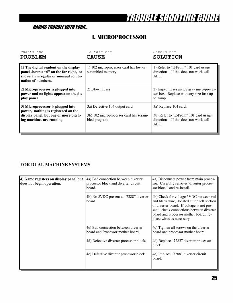
I. MICROPROCESSOR
1) The digital readout on the display
panel shows a “0” on the far right, or
shows an irregular or unusual combi-
nation of numbers.
1) 102 microprocessor card has lost or
scrambled memory.
1) Refer to “E-Prom” 101 card usage
directions. If this does not work call
ABC.
2) Microprocessor is plugged into
power and no lights appear on the dis-
play panel.
2) Blown fuses 2) Inspect fuses inside gray microproces-
sor box. Replace with any size fuse up
to 5amp.
3) Microprocessor is plugged into
power, nothing is registered on the
display panel, but one or more pitch-
ing machines are running.
3a) Defective 104 output card
3b) 102 microprocessor card has scram-
bled program.
3a) Replace 104 card.
3b) Refer to “E-Prom” 101 card usage
directions. If this does not work call
ABC.
What’s the Is this the Here’s the
PROBLEM CAUSE SOLUTION
4) Game registers on display panel but
does not begin operation.
4a) Bad connection between diverter
processor block and diverter circuit
board.
4b) No 5VDC present at “7288” diverter
board.
4c) Bad connection between diverter
board and Processor mother board.
4d) Defective diverter processor block.
4e) Defective diverter processor block.
4a) Disconnect power from main proces-
sor. Carefully remove “diverter proces-
sor block” and re-install.
4b) Check for voltage 5VDC between red
and black wire, located at top left section
of diverter board. If voltage is not pre-
sent, check connections between diverter
board and processor mother board, re-
place wires as necessary.
4c) Tighten all screws on the diverter
board and processor mother board.
4d) Replace “7283” diverter processor
block.
4e) Replace “7288” diverter circuit
board.
26
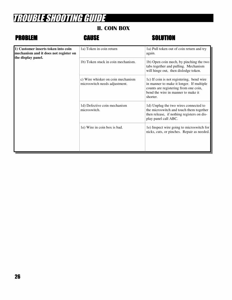
II. COIN BOX
1) Customer inserts token into coin
mechanism and it does not register on
the display panel.
1a) Token in coin return
1b) Token stuck in coin mechanism.
c) Wire whisker on coin mechanism
microswitch needs adjustment.
1d) Defective coin mechanism
microswitch.
1e) Wire in coin box is bad.
1a) Pull token out of coin return and try
again.
1b) Open coin mech, by pinching the two
tabs together and pulling. Mechanism
will hinge out, then dislodge token.
1c) If coin is not registering, bend wire
in manner to make it longer. If multiple
counts are registering from one coin,
bend the wire in manner to make it
shorter.
1d) Unplug the two wires connected to
the microswitch and touch them together
then release, if nothing registers on dis-
play panel call ABC.
1e) Inspect wire going to microswitch for
nicks, cuts, or pinches. Repair as needed.
PROBLEMPROBLEMPROBLEMPROBLEM CAUSECAUSECAUSECAUSE SOLUTIONSOLUTIONSOLUTIONSOLUTION
27
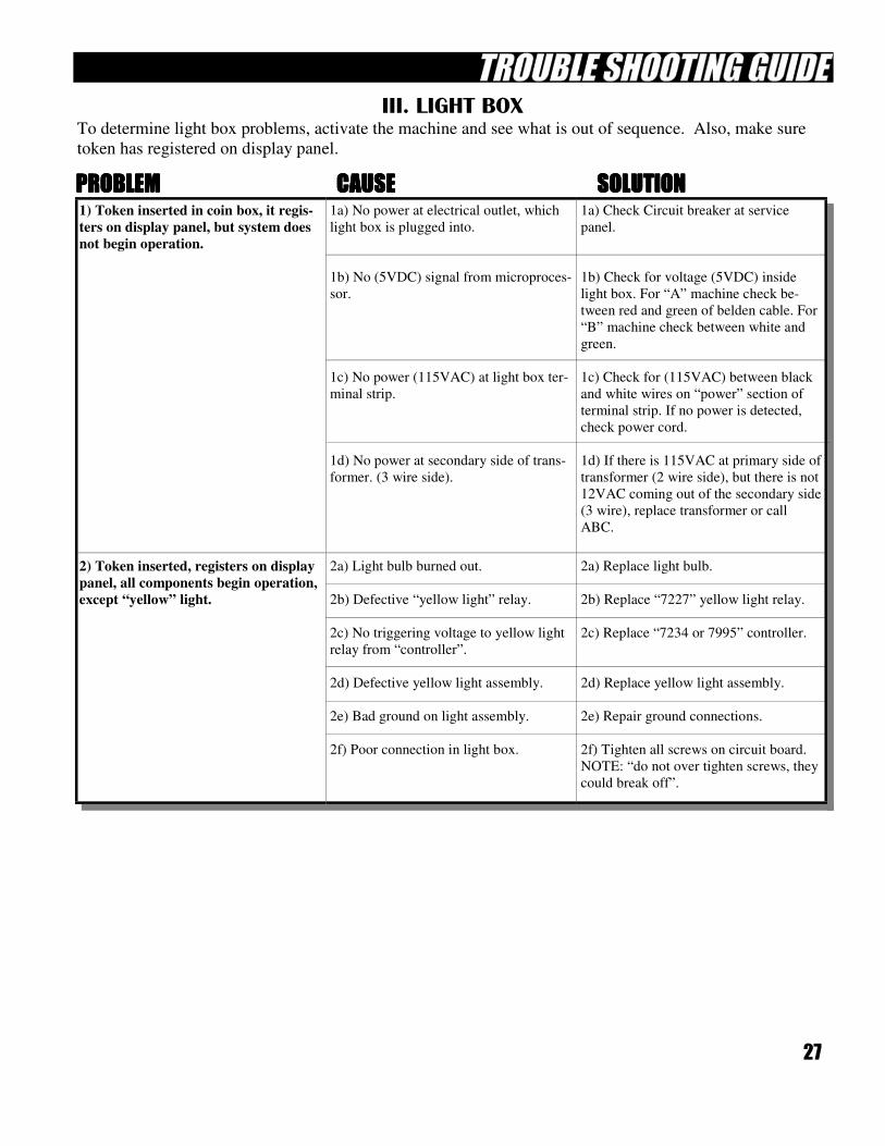
III. LIGHT BOX
To determine light box problems, activate the machine and see what is out of sequence. Also, make sure
token has registered on display panel.
PROBLEMPROBLEMPROBLEMPROBLEM CAUSECAUSECAUSECAUSE SOLUTIONSOLUTIONSOLUTIONSOLUTION 1) Token inserted in coin box, it regis-
ters on display panel, but system does
not begin operation.
1a) No power at electrical outlet, which
light box is plugged into.
1b) No (5VDC) signal from microproces-
sor.
1c) No power (115VAC) at light box ter-
minal strip.
1d) No power at secondary side of trans-
former. (3 wire side).
1a) Check Circuit breaker at service
panel.
1b) Check for voltage (5VDC) inside
light box. For “A” machine check be-
tween red and green of belden cable. For
“B” machine check between white and
green.
1c) Check for (115VAC) between black
and white wires on “power” section of
terminal strip. If no power is detected,
check power cord.
1d) If there is 115VAC at primary side of
transformer (2 wire side), but there is not
12VAC coming out of the secondary side
(3 wire), replace transformer or call
ABC.
2) Token inserted, registers on display
panel, all components begin operation,
except “yellow” light.
2a) Light bulb burned out.
2b) Defective “yellow light” relay.
2c) No triggering voltage to yellow light
relay from “controller”.
2d) Defective yellow light assembly.
2e) Bad ground on light assembly.
2f) Poor connection in light box.
2a) Replace light bulb.
2b) Replace “7227” yellow light relay.
2c) Replace “7234 or 7995” controller.
2d) Replace yellow light assembly.
2e) Repair ground connections.
2f) Tighten all screws on circuit board.
NOTE: “do not over tighten screws, they
could break off”.
28
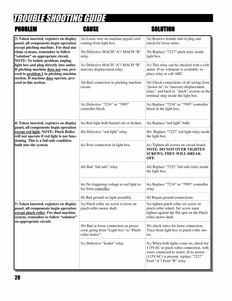
PROBLEMPROBLEMPROBLEMPROBLEM CAUSECAUSECAUSECAUSE SOLUTIONSOLUTIONSOLUTIONSOLUTION
3) Token inserted, registers on display
panel, all components begin operation
except pitching machine. For dual ma-
chine systems, remember to follow
“solution” on appropriate circuit.
NOTE: To isolate problem, unplug
light box and plug directly into outlet.
If pitching machine does not run, pro-
ceed to problem 1 in pitching machine
section. If machine does operate, pro-
ceed in this section.
3a) Loose wire on machine pigtail cord
coming from light box.
3b) Defective MACH “A”/ MACH “B”
relay.
3c) Defective MACH “A”/ MACH “B”
mercury displacement relay.
3d) Bad connection in pitching machine
circuit.
3e) Defective “7234” or “7995”
controller block.
3a) Remove female end of plug and
check for loose wires.
3b) Replace “7227” pitch relay inside
light box.
3c) This relay can be checked with a volt-
meter. If no voltmeter is available, re-
place relay or call ABC.
3d) Check connections of all wiring from
“power in”, to “mercury displacement
relay”, and back to “pitch” section on the
terminal strip inside the light box.
3e) Replace “7234” or “7995” controller
block in the light box.
4) Token inserted, registers on display
panel, all components begin operation
except red light. NOTE: Pinch Roller
will not operate if red light is not func-
tioning. This is a fail-safe condition
built into the system.
4a) Red light bulb burned out or broken.
4b) Defective “red light” relay.
4c) Poor connection in light box.
4d) Bad “fail safe” relay.
4e) No triggering voltage to red light re-
lay from controller.
4f) Bad ground on light assembly.
4a) Replace “red light” bulb.
4b) Replace “7227” red light relay inside
the light box.
4c) Tighten all screws on circuit board.
NOTE: DO NOT OVER TIGHTEN
SCREWS, THEY WILL BREAK
OFF.
4d) Replace “7225” fail-safe relay inside
the light box.
4e) Replace “7234” or “7995” controller
relay.
4f) Repair ground connections.
5) Token inserted, registers on display
panel, all components begin operation
except pinch roller. For dual machine
system, remember to follow “solution”
on appropriate circuit.
5a) Pinch roller set screw is loose on
pinch roller motor shaft.
5b) Bad or loose connection on power
cord, going from “Light box” to “Pinch
roller motor”.
5c) Defective “feeder” relay.
5a) tighten pinch roller set screw on
pinch roller wheel. Set screw must
tighten against the flat spot on the Pinch
roller motor shaft.
5b) check wires for loose connection.
Trace from light box to pinch roller mo-
tor.
5c) When both lights come on, check for
115VAC at pinch roller connection, with
wires connected to motor. If no power
(115VAC) is present, replace “7227”
Feed “A”/ Feed “B” relay.
29
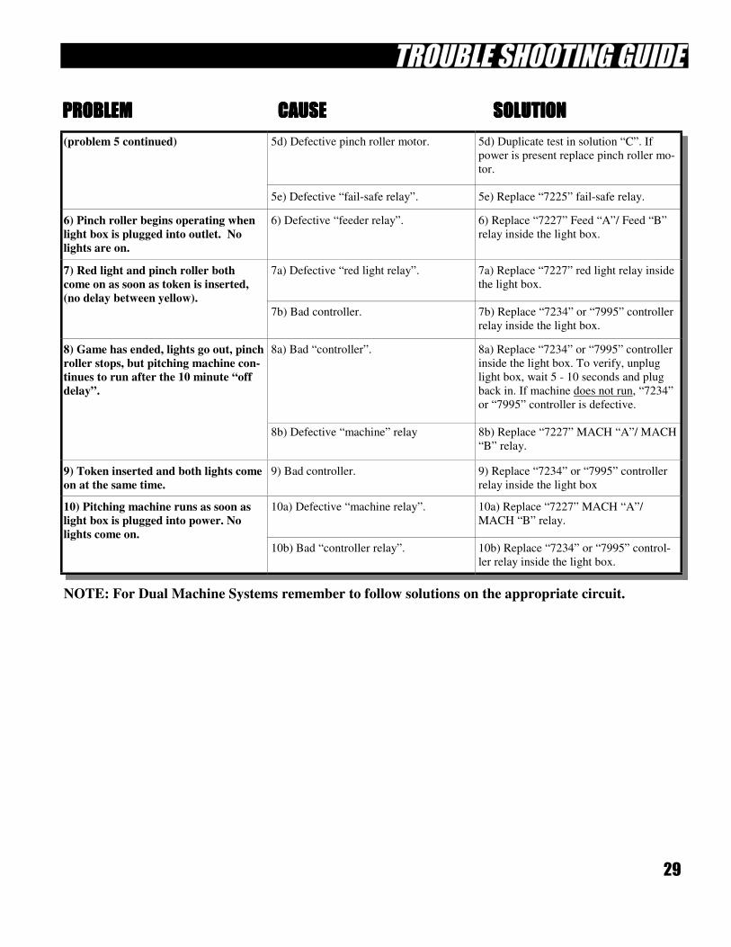
NOTE: For Dual Machine Systems remember to follow solutions on the appropriate circuit.
PROBLEMPROBLEMPROBLEMPROBLEM CAUSECAUSECAUSECAUSE SOLUTIONSOLUTIONSOLUTIONSOLUTION
(problem 5 continued) 5d) Defective pinch roller motor.
5e) Defective “fail-safe relay”.
5d) Duplicate test in solution “C”. If
power is present replace pinch roller mo-
tor.
5e) Replace “7225” fail-safe relay.
6) Pinch roller begins operating when
light box is plugged into outlet. No
lights are on.
6) Defective “feeder relay”. 6) Replace “7227” Feed “A”/ Feed “B”
relay inside the light box.
7) Red light and pinch roller both
come on as soon as token is inserted,
(no delay between yellow).
7a) Defective “red light relay”.
7b) Bad controller.
7a) Replace “7227” red light relay inside
the light box.
7b) Replace “7234” or “7995” controller
relay inside the light box.
8) Game has ended, lights go out, pinch
roller stops, but pitching machine con-
tinues to run after the 10 minute “off
delay”.
8a) Bad “controller”.
8b) Defective “machine” relay
8a) Replace “7234” or “7995” controller
inside the light box. To verify, unplug
light box, wait 5 - 10 seconds and plug
back in. If machine does not run, “7234”
or “7995” controller is defective.
8b) Replace “7227” MACH “A”/ MACH
“B” relay.
9) Token inserted and both lights come
on at the same time.
9) Bad controller. 9) Replace “7234” or “7995” controller
relay inside the light box
10) Pitching machine runs as soon as
light box is plugged into power. No
lights come on.
10a) Defective “machine relay”.
10b) Bad “controller relay”.
10a) Replace “7227” MACH “A”/
MACH “B” relay.
10b) Replace “7234” or “7995” control-
ler relay inside the light box.
30
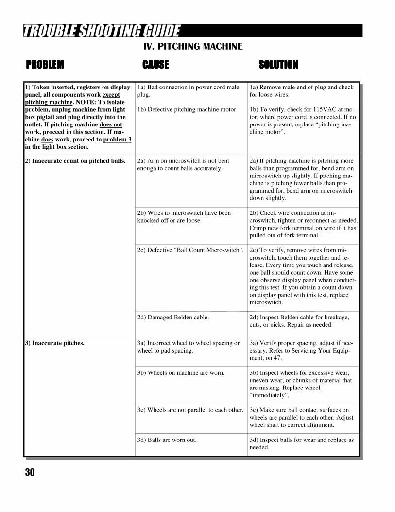
IV. PITCHING MACHINE
PROBLEMPROBLEMPROBLEMPROBLEM CAUSECAUSECAUSECAUSE SOLUTIONSOLUTIONSOLUTIONSOLUTION
1) Token inserted, registers on display
panel, all components work except
pitching machine. NOTE: To isolate
problem, unplug machine from light
box pigtail and plug directly into the
outlet. If pitching machine does not
work, proceed in this section. If ma-
chine does work, proceed to problem 3
in the light box section.
1a) Bad connection in power cord male
plug.
1b) Defective pitching machine motor.
1a) Remove male end of plug and check
for loose wires.
1b) To verify, check for 115VAC at mo-
tor, where power cord is connected. If no
power is present, replace “pitching ma-
chine motor”.
2) Inaccurate count on pitched balls. 2a) Arm on microswitch is not bent
enough to count balls accurately.
2b) Wires to microswitch have been
knocked off or are loose.
2c) Defective “Ball Count Microswitch”.
2d) Damaged Belden cable.
2a) If pitching machine is pitching more
balls than programmed for, bend arm on
microswitch up slightly. If pitching ma-
chine is pitching fewer balls than pro-
grammed for, bend arm on microswitch
down slightly.
2b) Check wire connection at mi-
croswitch, tighten or reconnect as needed.
Crimp new fork terminal on wire if it has
pulled out of fork terminal.
2c) To verify, remove wires from mi-
croswitch, touch them together and re-
lease. Every time you touch and release,
one ball should count down. Have some-
one observe display panel when conduct-
ing this test. If you obtain a count down
on display panel with this test, replace
microswitch.
2d) Inspect Belden cable for breakage,
cuts, or nicks. Repair as needed.
3) Inaccurate pitches. 3a) Incorrect wheel to wheel spacing or
wheel to pad spacing.
3b) Wheels on machine are worn.
3c) Wheels are not parallel to each other.
3d) Balls are worn out.
3a) Verify proper spacing, adjust if nec-
essary. Refer to Servicing Your Equip-
ment, on 47.
3b) Inspect wheels for excessive wear,
uneven wear, or chunks of material that
are missing. Replace wheel
“immediately”.
3c) Make sure ball contact surfaces on
wheels are parallel to each other. Adjust
wheel shaft to correct alignment.
3d) Inspect balls for wear and replace as
needed.
31
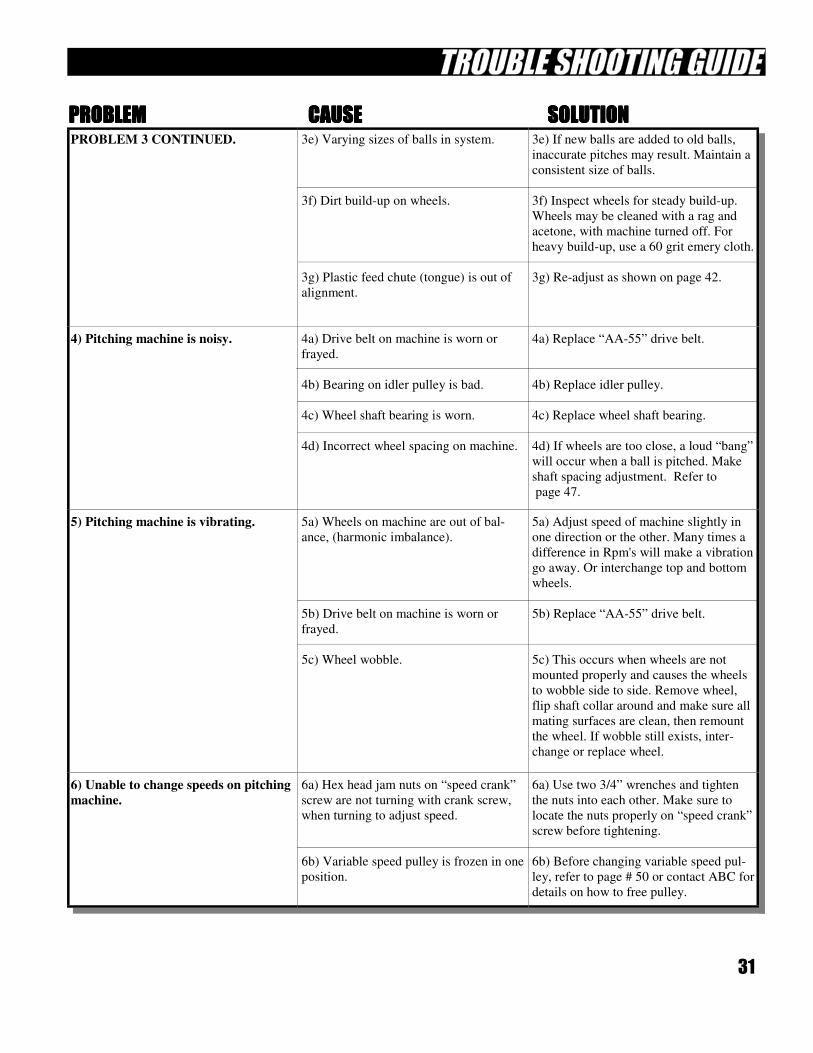
PROBLEM 3 CONTINUED. 3e) Varying sizes of balls in system.
3f) Dirt build-up on wheels.
3g) Plastic feed chute (tongue) is out of
alignment.
3e) If new balls are added to old balls,
inaccurate pitches may result. Maintain a
consistent size of balls.
3f) Inspect wheels for steady build-up.
Wheels may be cleaned with a rag and
acetone, with machine turned off. For
heavy build-up, use a 60 grit emery cloth.
3g) Re-adjust as shown on page 42.
4) Pitching machine is noisy. 4a) Drive belt on machine is worn or
frayed.
4b) Bearing on idler pulley is bad.
4c) Wheel shaft bearing is worn.
4d) Incorrect wheel spacing on machine.
4a) Replace “AA-55” drive belt.
4b) Replace idler pulley.
4c) Replace wheel shaft bearing.
4d) If wheels are too close, a loud “bang”
will occur when a ball is pitched. Make
shaft spacing adjustment. Refer to
page 47.
5) Pitching machine is vibrating. 5a) Wheels on machine are out of bal-
ance, (harmonic imbalance).
5b) Drive belt on machine is worn or
frayed.
5c) Wheel wobble.
5a) Adjust speed of machine slightly in
one direction or the other. Many times a
difference in Rpm's will make a vibration
go away. Or interchange top and bottom
wheels.
5b) Replace “AA-55” drive belt.
5c) This occurs when wheels are not
mounted properly and causes the wheels
to wobble side to side. Remove wheel,
flip shaft collar around and make sure all
mating surfaces are clean, then remount
the wheel. If wobble still exists, inter-
change or replace wheel.
6) Unable to change speeds on pitching
machine.
6a) Hex head jam nuts on “speed crank”
screw are not turning with crank screw,
when turning to adjust speed.
6b) Variable speed pulley is frozen in one
position.
6a) Use two 3/4” wrenches and tighten
the nuts into each other. Make sure to
locate the nuts properly on “speed crank”
screw before tightening.
6b) Before changing variable speed pul-
ley, refer to page # 50 or contact ABC for
details on how to free pulley.
PROBLEMPROBLEMPROBLEMPROBLEM CAUSECAUSECAUSECAUSE SOLUTIONSOLUTIONSOLUTIONSOLUTION
32
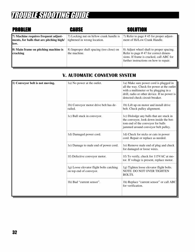
7) Machine requires frequent adjust-
ments, for balls that are pitching high/
low.
7) Locking nut on hi/low crank handle is
tightened in wrong location.
7) Refer to page # 45 for proper adjust-
ment of Hi/Low Crank Handle.
8) Main frame on pitching machine is
cracking
8) Improper shaft spacing (too close) on
the machine.
8) Adjust wheel shaft to proper spacing.
Refer to page # 47 for correct dimen-
sions. If frame is cracked, call ABC for
further instructions on how to repair.
V. AUTOMATIC CONVEYOR SYSTEM
1) Conveyor belt is not moving. 1a) No power at the outlet.
1b) Conveyor motor drive belt has de-
railed.
1c) Ball stuck in conveyor.
1d) Damaged power cord.
1e) Damage to male end of power cord.
1f) Defective conveyor motor.
1g) Loose elevator flight bolts catching
on top end of conveyor.
1h) Bad “current sensor”.
1a) Make sure power cord is plugged in
all the way. Check for power at the outlet
with a multimeter or by plugging in a
drill, radio or other device. If no power is
detected check circuit breaker.
1b) Lift up on motor and install drive
belt. Check pulley alignment.
1c) Dislodge any balls that are stuck in
the conveyor, look down inside the bot-
tom end of the conveyor for balls
jammed around conveyor belt pulley.
1d) Check for nicks or cuts in power
cord. Repair or replace as needed.
1e) Remove male end of plug and check
for damaged or loose wires.
1f) To verify, check for 115VAC at mo-
tor. If voltage is present, replace motor.
1g) Tighten loose elevator flight bolts.
NOTE: DO NOT OVER TIGHTEN
BOLTS.
1h) Replace “current sensor” or call ABC
for verification.
PROBLEMPROBLEMPROBLEMPROBLEM CAUSECAUSECAUSECAUSE SOLUTIONSOLUTIONSOLUTIONSOLUTION
33
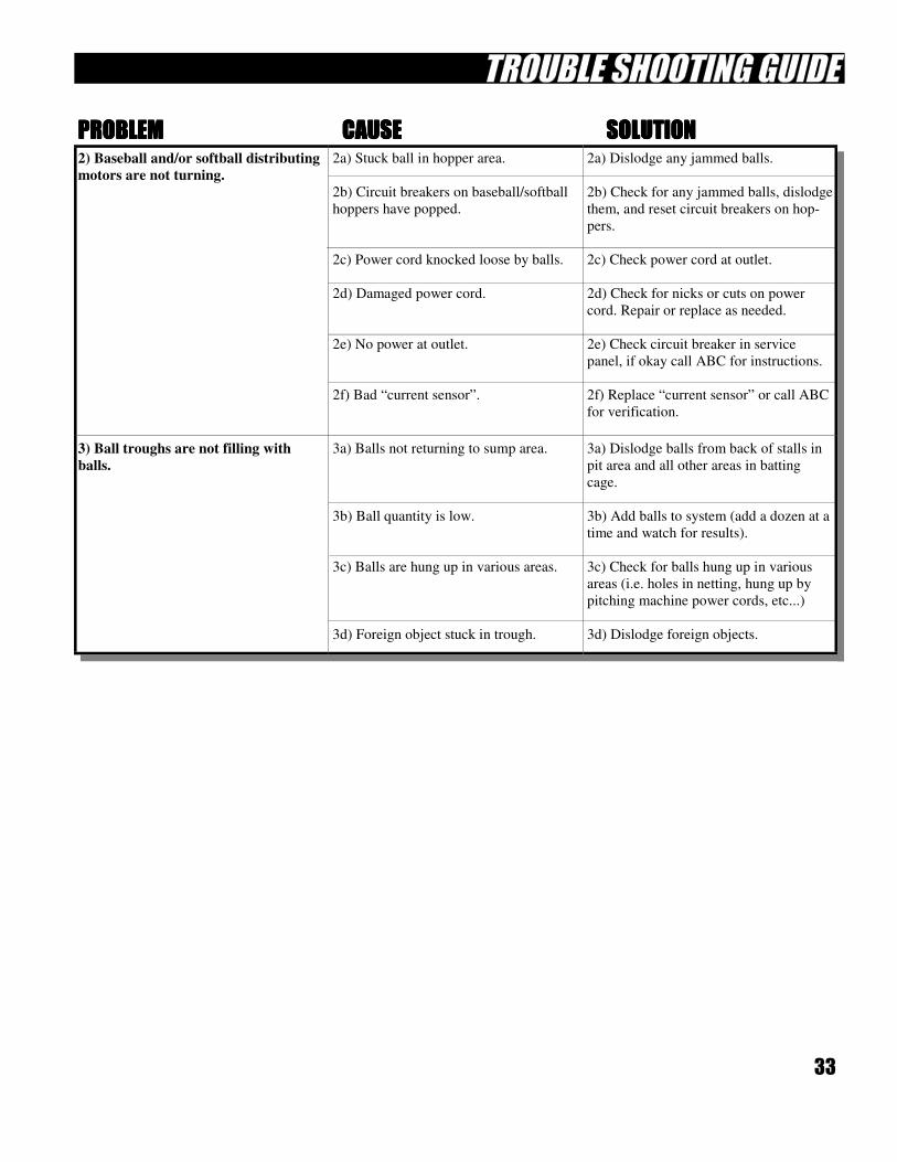
2) Baseball and/or softball distributing
motors are not turning.
2a) Stuck ball in hopper area.
2b) Circuit breakers on baseball/softball
hoppers have popped.
2c) Power cord knocked loose by balls.
2d) Damaged power cord.
2e) No power at outlet.
2f) Bad “current sensor”.
2a) Dislodge any jammed balls.
2b) Check for any jammed balls, dislodge
them, and reset circuit breakers on hop-
pers.
2c) Check power cord at outlet.
2d) Check for nicks or cuts on power
cord. Repair or replace as needed.
2e) Check circuit breaker in service
panel, if okay call ABC for instructions.
2f) Replace “current sensor” or call ABC
for verification.
3) Ball troughs are not filling with
balls.
3a) Balls not returning to sump area.
3b) Ball quantity is low.
3c) Balls are hung up in various areas.
3d) Foreign object stuck in trough.
3a) Dislodge balls from back of stalls in
pit area and all other areas in batting
cage.
3b) Add balls to system (add a dozen at a
time and watch for results).
3c) Check for balls hung up in various
areas (i.e. holes in netting, hung up by
pitching machine power cords, etc...)
3d) Dislodge foreign objects.
PROBLEMPROBLEMPROBLEMPROBLEM CAUSECAUSECAUSECAUSE SOLUTIONSOLUTIONSOLUTIONSOLUTION

34
35
MAINTENANCE PROCEDURES
Pages 35 thru 40
36
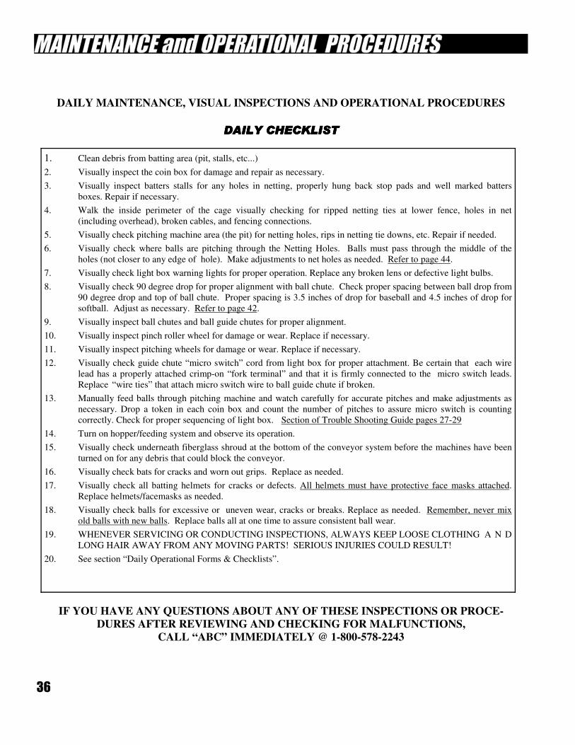
DAILY MAINTENANCE, VISUAL INSPECTIONS AND OPERATIONAL PROCEDURES
DAILY CHECKLISTDAILY CHECKLISTDAILY CHECKLISTDAILY CHECKLIST
1. Clean debris from batting area (pit, stalls, etc...)
2. Visually inspect the coin box for damage and repair as necessary.
3. Visually inspect batters stalls for any holes in netting, properly hung back stop pads and well marked batters
boxes. Repair if necessary.
4. Walk the inside perimeter of the cage visually checking for ripped netting ties at lower fence, holes in net
(including overhead), broken cables, and fencing connections.
5. Visually check pitching machine area (the pit) for netting holes, rips in netting tie downs, etc. Repair if needed.
6. Visually check where balls are pitching through the Netting Holes. Balls must pass through the middle of the
holes (not closer to any edge of hole). Make adjustments to net holes as needed. Refer to page 44.
7. Visually check light box warning lights for proper operation. Replace any broken lens or defective light bulbs.
8. Visually check 90 degree drop for proper alignment with ball chute. Check proper spacing between ball drop from
90 degree drop and top of ball chute. Proper spacing is 3.5 inches of drop for baseball and 4.5 inches of drop for
softball. Adjust as necessary. Refer to page 42.
9. Visually inspect ball chutes and ball guide chutes for proper alignment.
10. Visually inspect pinch roller wheel for damage or wear. Replace if necessary.
11. Visually inspect pitching wheels for damage or wear. Replace if necessary.
12. Visually check guide chute “micro switch” cord from light box for proper attachment. Be certain that each wire
lead has a properly attached crimp-on “fork terminal” and that it is firmly connected to the micro switch leads.
Replace “wire ties” that attach micro switch wire to ball guide chute if broken.
13. Manually feed balls through pitching machine and watch carefully for accurate pitches and make adjustments as
necessary. Drop a token in each coin box and count the number of pitches to assure micro switch is counting
correctly. Check for proper sequencing of light box. Section of Trouble Shooting Guide pages 27-29
14. Turn on hopper/feeding system and observe its operation.
15. Visually check underneath fiberglass shroud at the bottom of the conveyor system before the machines have been
turned on for any debris that could block the conveyor.
16. Visually check bats for cracks and worn out grips. Replace as needed.
17. Visually check all batting helmets for cracks or defects. All helmets must have protective face masks attached.
Replace helmets/facemasks as needed.
18. Visually check balls for excessive or uneven wear, cracks or breaks. Replace as needed. Remember, never mix
old balls with new balls. Replace balls all at one time to assure consistent ball wear.
19. WHENEVER SERVICING OR CONDUCTING INSPECTIONS, ALWAYS KEEP LOOSE CLOTHING A N D
LONG HAIR AWAY FROM ANY MOVING PARTS! SERIOUS INJURIES COULD RESULT!
20. See section “Daily Operational Forms & Checklists”.
IF YOU HAVE ANY QUESTIONS ABOUT ANY OF THESE INSPECTIONS OR PROCE-
DURES AFTER REVIEWING AND CHECKING FOR MALFUNCTIONS,
CALL “ABC” IMMEDIATELY @ 1-800-578-2243
37
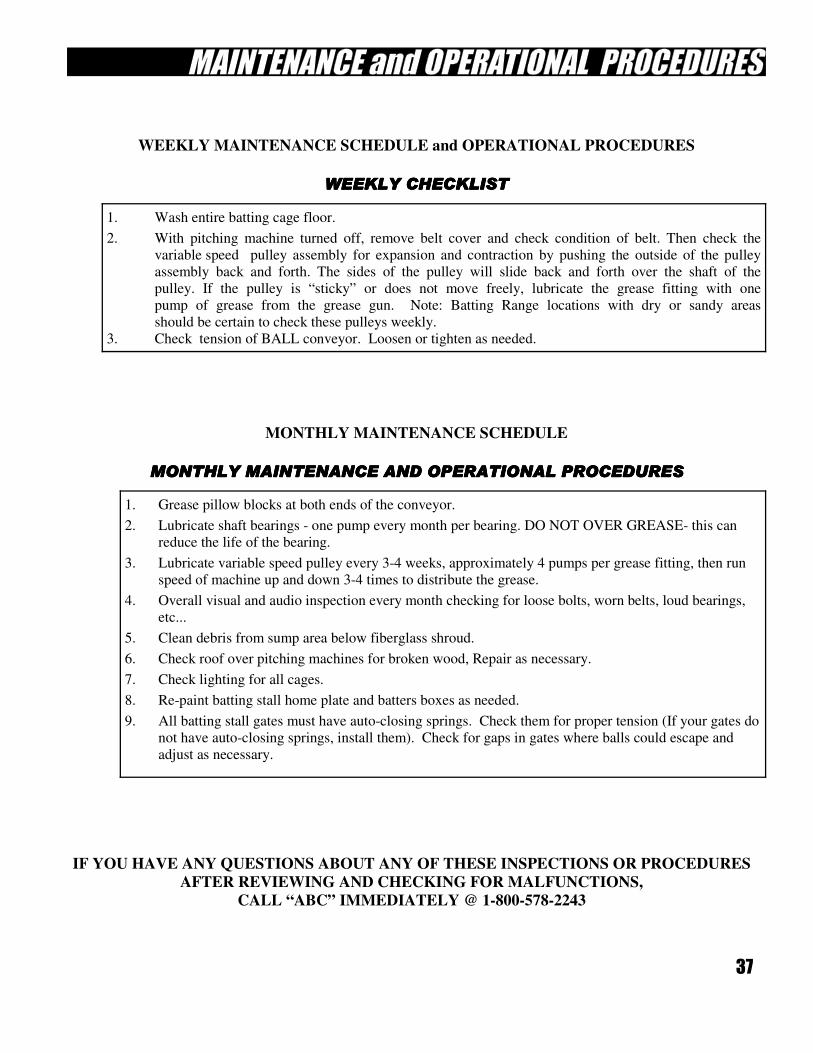
WEEKLY MAINTENANCE SCHEDULE and OPERATIONAL PROCEDURES
WEEKLY CHECKLISTWEEKLY CHECKLISTWEEKLY CHECKLISTWEEKLY CHECKLIST
MONTHLY MAINTENANCE SCHEDULE
MONTHLY MAINTENANCE AND OPERATIONAL PROCEDURESMONTHLY MAINTENANCE AND OPERATIONAL PROCEDURESMONTHLY MAINTENANCE AND OPERATIONAL PROCEDURESMONTHLY MAINTENANCE AND OPERATIONAL PROCEDURES
1. Wash entire batting cage floor.
2. With pitching machine turned off, remove belt cover and check condition of belt. Then check the
variable speed pulley assembly for expansion and contraction by pushing the outside of the pulley
assembly back and forth. The sides of the pulley will slide back and forth over the shaft of the
pulley. If the pulley is “sticky” or does not move freely, lubricate the grease fitting with one
pump of grease from the grease gun. Note: Batting Range locations with dry or sandy areas
should be certain to check these pulleys weekly.
3. Check tension of BALL conveyor. Loosen or tighten as needed.
1. Grease pillow blocks at both ends of the conveyor.
2. Lubricate shaft bearings - one pump every month per bearing. DO NOT OVER GREASE- this can
reduce the life of the bearing.
3. Lubricate variable speed pulley every 3-4 weeks, approximately 4 pumps per grease fitting, then run
speed of machine up and down 3-4 times to distribute the grease.
4. Overall visual and audio inspection every month checking for loose bolts, worn belts, loud bearings,
etc...
5. Clean debris from sump area below fiberglass shroud.
6. Check roof over pitching machines for broken wood, Repair as necessary.
7. Check lighting for all cages.
8. Re-paint batting stall home plate and batters boxes as needed.
9. All batting stall gates must have auto-closing springs. Check them for proper tension (If your gates do
not have auto-closing springs, install them). Check for gaps in gates where balls could escape and
adjust as necessary.
IF YOU HAVE ANY QUESTIONS ABOUT ANY OF THESE INSPECTIONS OR PROCEDURES
AFTER REVIEWING AND CHECKING FOR MALFUNCTIONS,
CALL “ABC” IMMEDIATELY @ 1-800-578-2243
38
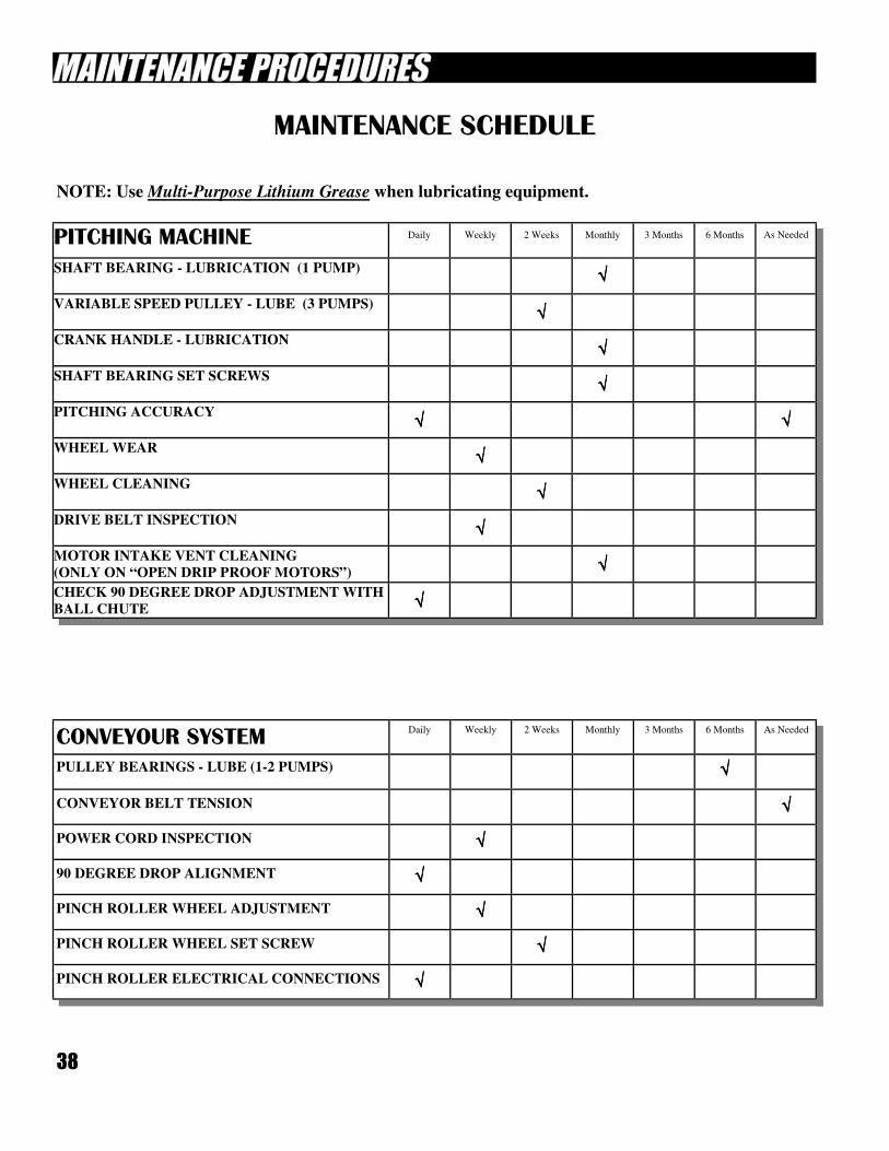
CONVEYOUR SYSTEM Daily Weekly 2 Weeks Monthly 3 Months 6 Months As Needed
PULLEY BEARINGS - LUBE (1-2 PUMPS) √√√√
CONVEYOR BELT TENSION √√√√
POWER CORD INSPECTION √√√√
90 DEGREE DROP ALIGNMENT √√√√
PINCH ROLLER WHEEL ADJUSTMENT √√√√
PINCH ROLLER WHEEL SET SCREW √√√√
PINCH ROLLER ELECTRICAL CONNECTIONS √√√√
MAINTENANCE SCHEDULE
PITCHING MACHINE Daily Weekly 2 Weeks Monthly 3 Months 6 Months As Needed
SHAFT BEARING - LUBRICATION (1 PUMP) √√√√
VARIABLE SPEED PULLEY - LUBE (3 PUMPS) √√√√
CRANK HANDLE - LUBRICATION √√√√
SHAFT BEARING SET SCREWS √√√√
PITCHING ACCURACY √√√√ √√√√
WHEEL WEAR √√√√
WHEEL CLEANING √√√√
DRIVE BELT INSPECTION √√√√
MOTOR INTAKE VENT CLEANING
(ONLY ON “OPEN DRIP PROOF MOTORS”) √√√√
CHECK 90 DEGREE DROP ADJUSTMENT WITH
BALL CHUTE √√√√
NOTE: Use Multi-Purpose Lithium Grease when lubricating equipment.
39
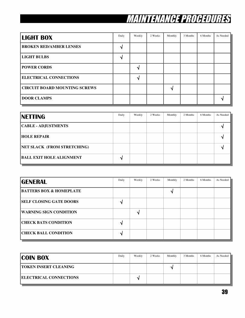
COIN BOX Daily Weekly 2 Weeks Monthly 3 Months 6 Months As Needed
TOKEN INSERT CLEANING √√√√
ELECTRICAL CONNECTIONS √√√√
GENERAL Daily Weekly 2 Weeks Monthly 2 Months 6 Months As Needed
BATTERS BOX & HOMEPLATE √√√√
SELF CLOSING GATE DOORS √√√√
WARNING SIGN CONDITION √√√√
CHECK BATS CONDITION √√√√
CHECK BALL CONDITION √√√√
NETTING Daily Weekly 2 Weeks Monthly 2 Months 6 Months As Needed
CABLE - ADJUSTMENTS √√√√
HOLE REPAIR √√√√
NET SLACK (FROM STRETCHING) √√√√
BALL EXIT HOLE ALIGNMENT √√√√
LIGHT BOX Daily Weekly 2 Weeks Monthly 3 Months 6 Months As Needed
LIGHT BULBS √√√√
POWER CORDS √√√√
ELECTRICAL CONNECTIONS √√√√
CIRCUIT BOARD MOUNTING SCREWS √√√√
DOOR CLAMPS √√√√
BROKEN RED/AMBER LENSES √√√√
40
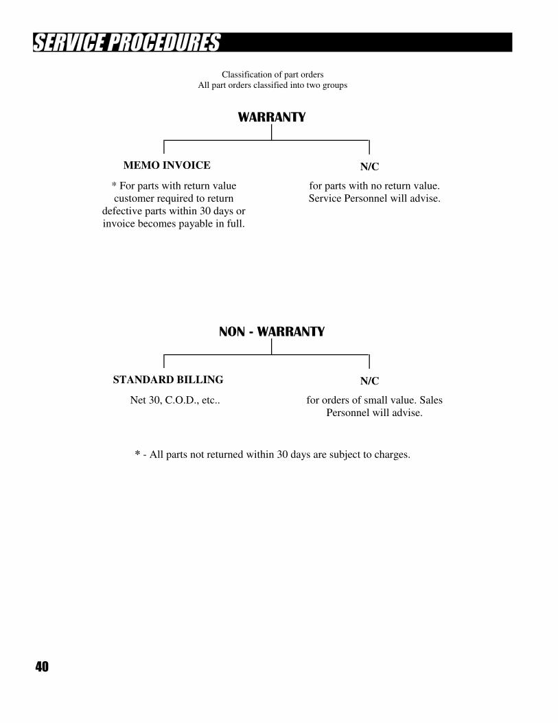
Classification of part orders
All part orders classified into two groups
WARRANTY
MEMO INVOICE N/C
* For parts with return value
customer required to return
defective parts within 30 days or
invoice becomes payable in full.
for parts with no return value.
Service Personnel will advise.
NON - WARRANTY
STANDARD BILLING N/C
Net 30, C.O.D., etc.. for orders of small value. Sales
Personnel will advise.
* - All parts not returned within 30 days are subject to charges.
41
SERVICING YOUR EQUIPMENT
Pages 41 thru 58
42
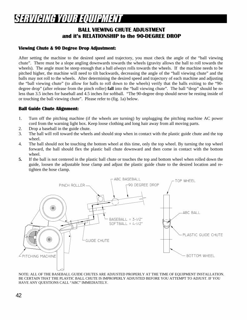
BALL VIEWING CHUTE ADJUSTMENT and it’s RELATIONSHIP to the 90-DEGREE DROP
Viewing Chute & 90 Degree Drop Adjustment: After setting the machine to the desired speed and trajectory, you must check the angle of the “ball viewing chute”. There must be a slope angling downwards towards the wheels (gravity allows the ball to roll towards the wheels). The angle must be steep enough that a ball always rolls towards the wheels. If the machine needs to be pitched higher, the machine will need to tilt backwards, decreasing the angle of the “ball viewing chute” and the balls may not roll to the wheels. After determining the desired speed and trajectory of each machine and adjusting the “ball viewing chute” (to allow for balls to roll down to the wheels) verify that the balls exiting to the “90-degree drop” (after release from the pinch roller) fall into the “ball viewing chute”. The ball “drop” should be no less than 3.5 inches for baseball and 4.5 inches for softball. “The 90-degree drop should never be resting inside of or touching the ball viewing chute”. Please refer to (fig. 1a) below. Ball Guide Chute Alignment: 1. Turn off the pitching machine (if the wheels are turning) by unplugging the pitching machine AC power
cord from the warning light box. Keep loose clothing and long hair away from all moving parts. 2. Drop a baseball in the guide chute. 3. The ball will roll toward the wheels and should stop when in contact with the plastic guide chute and the top
wheel. 4. The ball should not be touching the bottom wheel at this time, only the top wheel. By turning the top wheel
forward, the ball should flex the plastic ball chute downward and then come in contact with the bottom wheel.
5. If the ball is not centered in the plastic ball chute or touches the top and bottom wheel when rolled down the guide, loosen the adjustable hose clamp and adjust the plastic guide chute to the desired location and re-tighten the hose clamp.
NOTE: ALL OF THE BASEBALL GUIDE CHUTES ARE ADJUSTED PROPERLY AT THE TIME OF EQUIPMENT INSTALLATION. BE CERTAIN THAT THE PLASTIC BALL CHUTE IS IMPROPERLY ADJUSTED BEFORE YOU ATTEMPT TO ADJUST. IF YOU HAVE ANY QUESTIONS CALL “ABC” IMMEDIATELY.
43
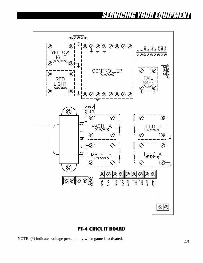
PT-4 CIRCUIT BOARD NOTE: (*) indicates voltage present only when game is activated.
44
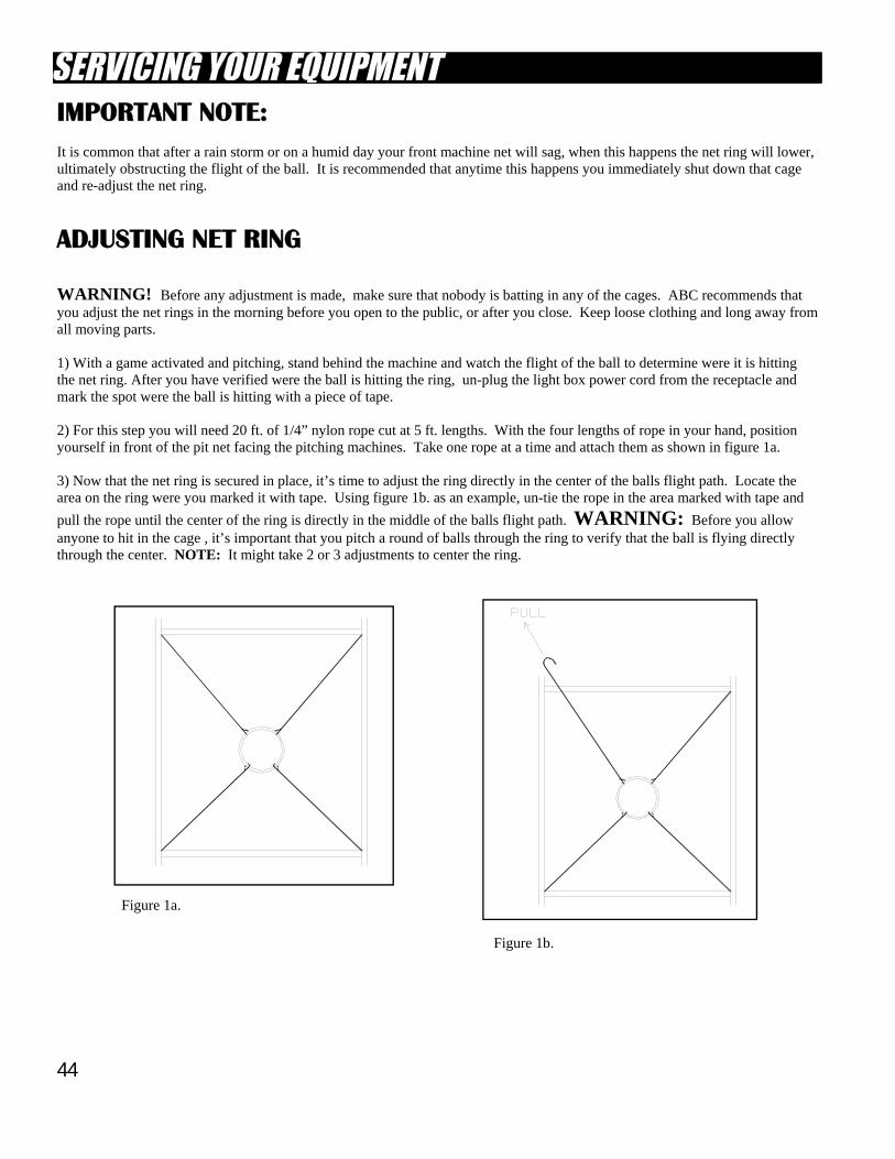
IMPORTANT NOTE: It is common that after a rain storm or on a humid day your front machine net will sag, when this happens the net ring will lower, ultimately obstructing the flight of the ball. It is recommended that anytime this happens you immediately shut down that cage and re-adjust the net ring.
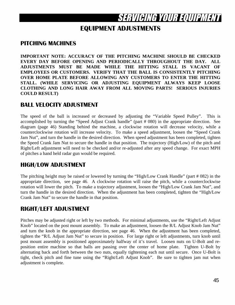
ADJUSTING NET RING WARNING! Before any adjustment is made, make sure that nobody is batting in any of the cages. ABC recommends that you adjust the net rings in the morning before you open to the public, or after you close. Keep loose clothing and long away from all moving parts. 1) With a game activated and pitching, stand behind the machine and watch the flight of the ball to determine were it is hitting the net ring. After you have verified were the ball is hitting the ring, un-plug the light box power cord from the receptacle and mark the spot were the ball is hitting with a piece of tape. 2) For this step you will need 20 ft. of 1/4” nylon rope cut at 5 ft. lengths. With the four lengths of rope in your hand, position yourself in front of the pit net facing the pitching machines. Take one rope at a time and attach them as shown in figure 1a. 3) Now that the net ring is secured in place, it’s time to adjust the ring directly in the center of the balls flight path. Locate the area on the ring were you marked it with tape. Using figure 1b. as an example, un-tie the rope in the area marked with tape and
pull the rope until the center of the ring is directly in the middle of the balls flight path. WARNING: Before you allow anyone to hit in the cage , it’s important that you pitch a round of balls through the ring to verify that the ball is flying directly through the center. NOTE: It might take 2 or 3 adjustments to center the ring.
Figure 1a.
Figure 1b.
45
EQUIPMENT ADJUSTMENTS
PITCHING MACHINES IMPORTANT NOTE: ACCURACY OF THE PITCHING MACHINE SHOULD BE CHECKED EVERY DAY BEFORE OPENING AND PERIODICALLY THROUGHOUT THE DAY. ALL ADJUSTMENTS MUST BE MADE WHILE THE HITTING STALL IS VACANT OF EMPLOYEES OR CUSTOMERS. VERIFY THAT THE BALL IS CONSISTENTLY PITCHING OVER HOME PLATE BEFORE ALLOWING ANY CUSTOMERS TO ENTER THE HITTING STALL. (WHILE SERVICING OR ADJUSTING EQUIPMENT ALWAYS KEEP LOOSE CLOTHING AND LONG HAIR AWAY FROM ALL MOVING PARTS! SERIOUS INJURIES COULD RESULT)
BALL VELOCITY ADJUSTMENT The speed of the ball is increased or decreased by adjusting the “Variable Speed Pulley”. This is accomplished by turning the “Speed Adjust Crank handle” (part # 080) in the appropriate direction. See diagram (page 46) Standing behind the machine, a clockwise rotation will decrease velocity, while a counterclockwise rotation will increase velocity. To make a speed adjustment, loosen the “Speed Crank Jam Nut”, and turn the handle in the desired direction. When speed adjustment has been completed, tighten the Speed Crank Jam Nut to secure the handle in that position. The trajectory (High/Low) of the pitch and Right/Left adjustment will need to be checked and/or re-adjusted after any speed change. For exact MPH of pitches a hand held radar gun would be required.
HIGH/LOW ADJUSTMENT The pitching height may be raised or lowered by turning the “High/Low Crank Handle” (part # 082) in the appropriate direction, see page 46. A clockwise rotation will raise the pitch, while a counterclockwise rotation will lower the pitch. To make a trajectory adjustment, loosen the “High/Low Crank Jam Nut”, and turn the handle in the desired direction. When the adjustment has been completed, tighten the “High/Low Crank Jam Nut” to secure the handle in that position.
RIGHT/LEFT ADJUSTMENT Pitches may be adjusted right or left by two methods. For minimal adjustments, use the “Right/Left Adjust Knob” located on the post mount assembly. To make an adjustment, loosen the R/L Adjust Knob Jam Nut” and turn the knob in the appropriate direction, see page 46. When the adjustment has been completed, tighten the “R/L Adjust Jam Nut” to secure in position. For large right or left adjustments, turn knob until post mount assembly is positioned approximately halfway of it’s travel. Loosen nuts on U-Bolt and re-position entire machine so that balls are passing over the center of home plate. Tighten U-Bolt by alternating back and forth between the two nuts, equally tightening each nut until secure. Once U-Bolt is tight, check pitch and fine tune using the “Right/Left Adjust Knob”. Be sure to tighten jam nut when adjustment is complete.
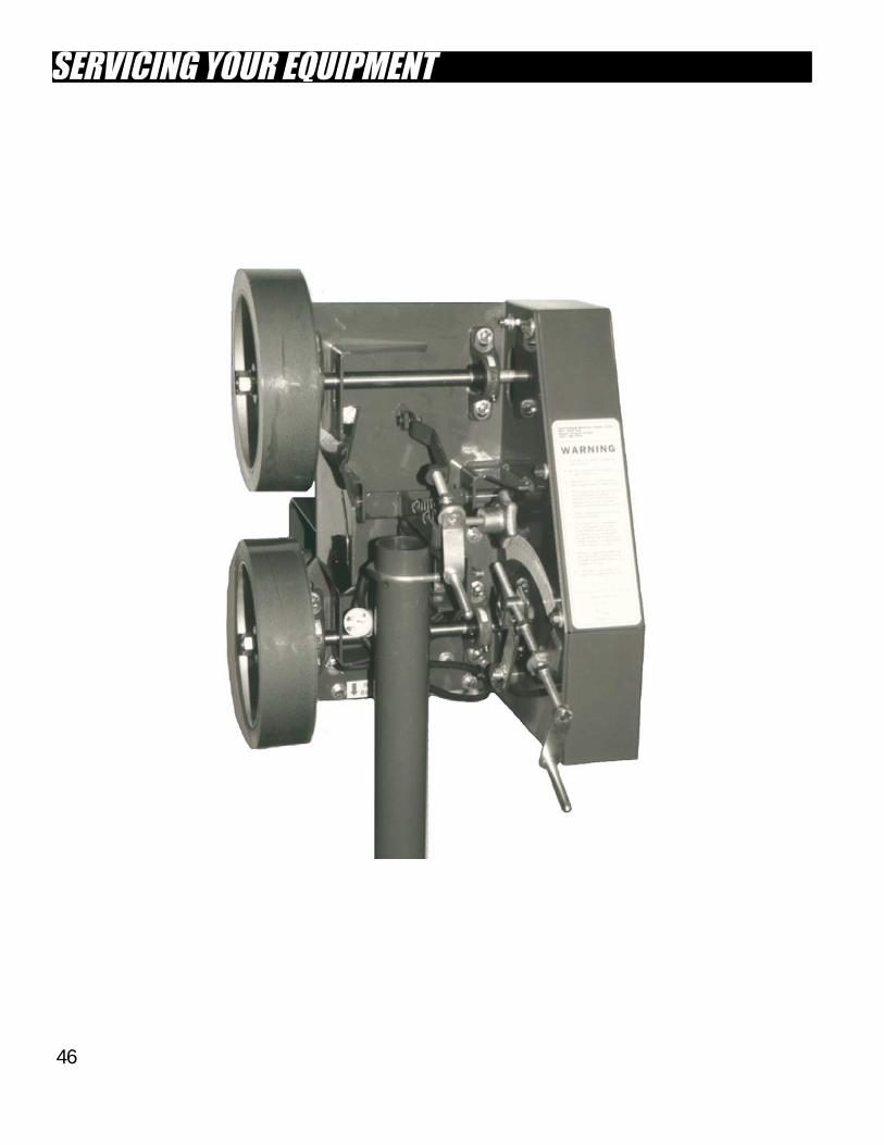
46
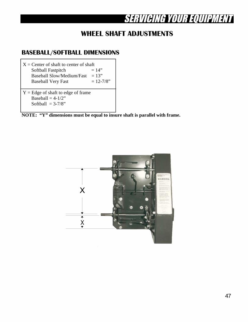
47
WHEEL SHAFT ADJUSTMENTS
BASEBALL/SOFTBALL DIMENSIONS X = Center of shaft to center of shaft Softball Fastpitch = 14” Baseball Slow/Medium/Fast = 13” Baseball Very Fast = 12-7/8” Y = Edge of shaft to edge of frame Baseball = 4-1/2” Softball = 3-7/8” NOTE: “Y” dimensions must be equal to insure shaft is parallel with frame.
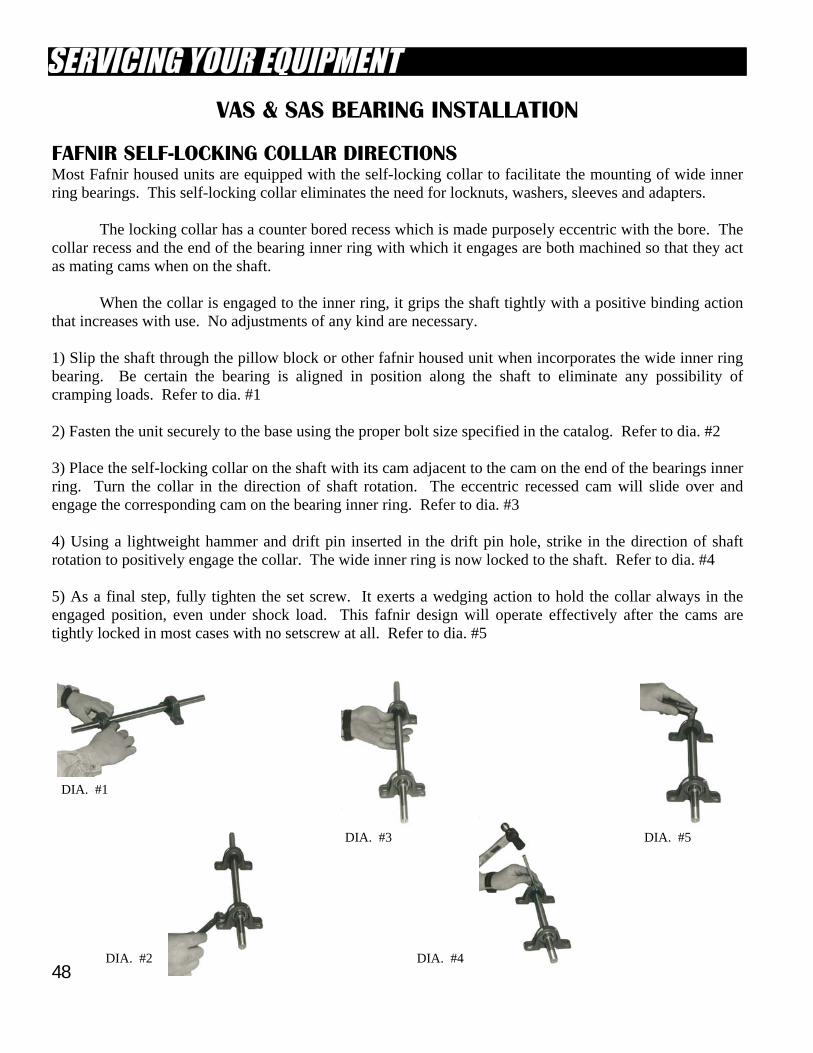
48
VAS & SAS BEARING INSTALLATION
FAFNIR SELF-LOCKING COLLAR DIRECTIONS Most Fafnir housed units are equipped with the self-locking collar to facilitate the mounting of wide inner ring bearings. This self-locking collar eliminates the need for locknuts, washers, sleeves and adapters. The locking collar has a counter bored recess which is made purposely eccentric with the bore. The collar recess and the end of the bearing inner ring with which it engages are both machined so that they act as mating cams when on the shaft. When the collar is engaged to the inner ring, it grips the shaft tightly with a positive binding action that increases with use. No adjustments of any kind are necessary. 1) Slip the shaft through the pillow block or other fafnir housed unit when incorporates the wide inner ring bearing. Be certain the bearing is aligned in position along the shaft to eliminate any possibility of cramping loads. Refer to dia. #1 2) Fasten the unit securely to the base using the proper bolt size specified in the catalog. Refer to dia. #2 3) Place the self-locking collar on the shaft with its cam adjacent to the cam on the end of the bearings inner ring. Turn the collar in the direction of shaft rotation. The eccentric recessed cam will slide over and engage the corresponding cam on the bearing inner ring. Refer to dia. #3 4) Using a lightweight hammer and drift pin inserted in the drift pin hole, strike in the direction of shaft rotation to positively engage the collar. The wide inner ring is now locked to the shaft. Refer to dia. #4 5) As a final step, fully tighten the set screw. It exerts a wedging action to hold the collar always in the engaged position, even under shock load. This fafnir design will operate effectively after the cams are tightly locked in most cases with no setscrew at all. Refer to dia. #5
DIA. #1
DIA. #2
DIA. #3
DIA. #4
DIA. #5
49
LIGHT BOX FUNCTIONS YELLOW LIGHT RELAY (#7227) This Relay turns the yellow light on when the game is activated either by the display panel or when a coin is dropped through the coin box. RED LIGHT RELAY (#7227) This relay turns the red light on 10 seconds after the yellow light is activated. FAIL-SAFE RELAY (#7225) The 7225 Fail-safe relay is an added safety feature in the PT-4 & PT-4Dual light box. The 12vac power for the red light flows through the 7225, this voltage triggers the 7225 which then provides a ground for the feeder relay(s). If the red light bulb is burnt out, the circuit remains open and prevents the feeder relay(s) from functioning. “MACHINE A” & “MACHINE B” RELAY(S) (#7227) “Machine A” relay (7227) provides triggering voltage (120vac) to the mercury displacement relay. The mercury displacement relay provides the power (120vac) for the pitching “Machine A” to operate. In a PT-4Dual light box “Machine B” relay (7227) provides triggering voltage to the additional mercury displacement relay. This mercury displacement relay would then provide power for the pitching “Machine B” to operate. “FEEDER A” & “FEEDER B” RELAY(S) (#7227) “Feeder A” relay (7227) provides power (120vac) to the pinch roller motor. In a PT-4Dual light box “Feeder B” relay (7227) provides power (120vac) to the dual system pinch roller motor. Operation of both motors would be discontinued if the red light bulb is burnt out. MERCURY DISPLACEMENT RELAY (#6X597) This is the large relay mounted inside the PT-4 light box, it is used to turn on the pitching machine motor. If you have a PT-4Dual light box there will be (2) large relays mounted inside the light box. One of the relays turns on the baseball machine motor (Machine A) and the other relay turn on the softball machine motor (Machine B). NOTE: If you own a PT-4Dual light box each relay operates individually with its designated pitching machine and not as one. CONTROLLER (#7995) The controller has the logic that controls the sequence in which the relays are turned on and off. The game sequence is as follows: 1) At the time of the coin drop, both the yellow light and the pitching machine motor turn on. 2) Ten seconds later, both the red light and the pinch roller motor turn on. Balls begin to pitch. 3) After the last ball is pitched, both the red and yellow lights and the pinch roller turn off. The pitching machine will continue for ten minutes. 4) After 8-10 minutes, if no one has started a new game by dropping a coin or via master panel, the pitching machine will turn off. NOTE: If there is any irregularity in timing or sequence, change the #7995 controller. TRANSFORMER The transformer lowers the voltage from 115vac to 12-14vac for the red and yellow lights. These are automotive lights and can be purchased at any auto parts retailer.
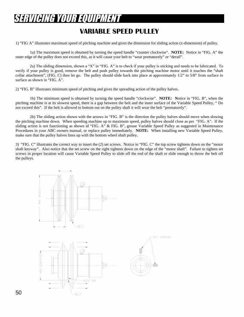
50
VARIABLE SPEED PULLEY
1) “FIG A” illustrates maximum speed of pitching machine and gives the dimension for sliding action (x-dimension) of pulley. 1a) The maximum speed is obtained by turning the speed handle “counter clockwise”. NOTE: Notice in “FIG. A” the outer edge of the pulley does not exceed this, as it will cause your belt to “wear prematurely” or “derail”. 2a) The sliding dimension, shown a “X” in “FIG. A” is to check if your pulley is sticking and needs to be lubricated. To verify if your pulley is good, remove the belt and push pulley towards the pitching machine motor until it touches the “shaft collar attachment”, (FIG. C) then let go. The pulley should slide back into place at approximately 1/2” to 5/8” from surface to surface as shown in “FIG. A”. 2) “FIG. B” illustrates minimum speed of pitching and gives the spreading action of the pulley halves. 1b) The minimum speed is obtained by turning the speed handle “clockwise”. NOTE: Notice in “FIG. B”, when the pitching machine is at its slowest speed, there is a gap between the belt and the inner surface of the Variable Speed Pulley, “ Do not exceed this”. If the belt is allowed to bottom out on the pulley shaft it will wear the belt “prematurely”. 2b) The sliding action shown with the arrows in “FIG. B” is the direction the pulley halves should move when slowing the pitching machine down. When speeding machine up to maximum speed, pulley halves should close as per “FIG. A”. If the sliding action is not functioning as shown id “FIG. A” & FIG. B”, grease Variable Speed Pulley as suggested in Maintenance Procedures in your ABC owners manual, or replace pulley immediately. NOTE: When installing new Variable Speed Pulley, make sure that the pulley halves lines up with the bottom wheel shaft pulley. 3) “FIG. C” illustrates the correct way to insert the (2) set screws. Notice in “FIG. C” the top screw tightens down on the “motor shaft keyway”. Also notice that the set screw on the right tightens down on the edge of the “motor shaft”. Failure to tighten set screws in proper location will cause Variable Speed Pulley to slide off the end of the shaft or slide enough to throw the belt off the pulleys.
51
BATTING CAGE WINTERIZATION
GRAVITY FLOW DRAIN SYSTEM 1) Turn power off leading to A/R Conveyor System and pitching machines. 2) Place plastic bag over pitching machine, light boxes and coin boxes, ventilate bottom of bags. 3) Remove fiberglass shroud then disconnect conveyor from hopper and place in area away from rain, snow, sleet etc... 4) Netting System: The safest method to protect your net and pipe structure would be to un-tie the rope lanyards at every perimeter pole and let the net hang straight down from the net collar. Another method that would give you a comfortable degree of safety and saves you the job of pulling the net back up in the spring is as follows. a) Tie a piece of net twine to the metal ring in the net, then tie it off to the horizontal rail. b) Un-tie rope lanyards from perimeter vertical pipe, leaving un-tied end of rope resting on the canopy net. This will hold the net in place, yet the single strand of twine would break loose under a heavy load. Upon opening in the spring you would need to re-tie the rope lanyards to the vertical pipes. 5) Unplug Micro-Processor power cord from outlet and remove all processor cards located in the middle of Micro-Processor Box, then place cards in a safe area.
ELECTRIC POWERED SUMP PUMP DRAIN SYSTEM 1) Place plastic bag over all pitching machines, then ventilate the bottom of each bag. 2) Remove light boxes and place in a covered area away from direct weather. Cover up any bare wiring and place away from flooding levels. 3) Remove fiberglass shroud then disconnect conveyor from hopper and place in area away from rain, snow, sleet, etc... 4) Netting System: Refer to #4 of “gravity flow drain system”. 5) Unplug Micro-Processor power cord from outlet and remove all processor cards located in the middle of Micro-Processor Box, then place cards in a safe place. NOTE: If you have any questions before winterizing please call ABC’s Customer Service Department for questions.
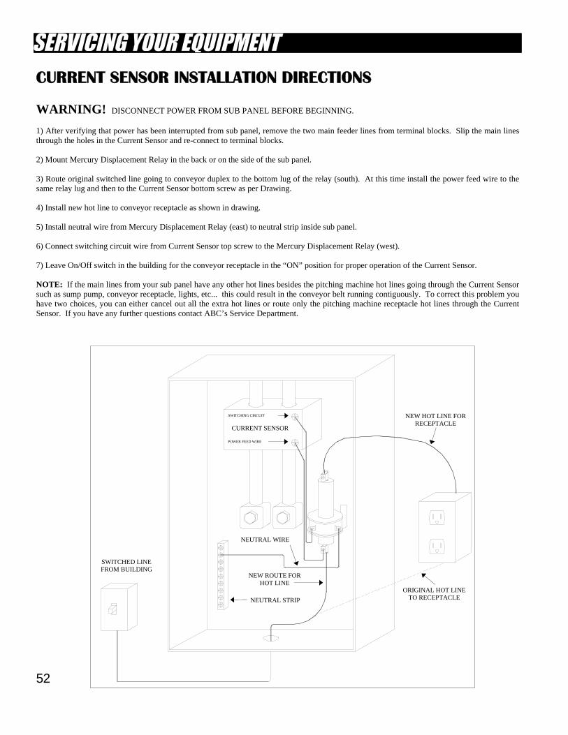
52
CURRENT SENSOR INSTALLATION DIRECTIONS WARNING! DISCONNECT POWER FROM SUB PANEL BEFORE BEGINNING. 1) After verifying that power has been interrupted from sub panel, remove the two main feeder lines from terminal blocks. Slip the main lines through the holes in the Current Sensor and re-connect to terminal blocks. 2) Mount Mercury Displacement Relay in the back or on the side of the sub panel. 3) Route original switched line going to conveyor duplex to the bottom lug of the relay (south). At this time install the power feed wire to the same relay lug and then to the Current Sensor bottom screw as per Drawing. 4) Install new hot line to conveyor receptacle as shown in drawing. 5) Install neutral wire from Mercury Displacement Relay (east) to neutral strip inside sub panel. 6) Connect switching circuit wire from Current Sensor top screw to the Mercury Displacement Relay (west). 7) Leave On/Off switch in the building for the conveyor receptacle in the “ON” position for proper operation of the Current Sensor. NOTE: If the main lines from your sub panel have any other hot lines besides the pitching machine hot lines going through the Current Sensor such as sump pump, conveyor receptacle, lights, etc... this could result in the conveyor belt running contiguously. To correct this problem you have two choices, you can either cancel out all the extra hot lines or route only the pitching machine receptacle hot lines through the Current Sensor. If you have any further questions contact ABC’s Service Department.
CURRENT SENSOR
SWITCHED LINE FROM BUILDING
NEW HOT LINE FOR RECEPTACLE
ORIGINAL HOT LINE TO RECEPTACLE
NEW ROUTE FOR HOT LINE
NEUTRAL STRIP
NEUTRAL WIRE
POWER FEED WIRE
SWITCHING CIRCUIT
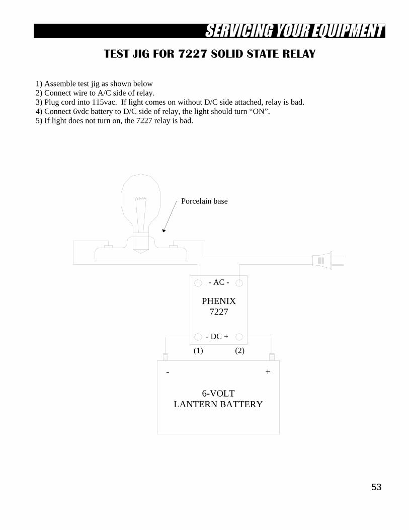
53
TEST JIG FOR 7227 SOLID STATE RELAY 1) Assemble test jig as shown below 2) Connect wire to A/C side of relay. 3) Plug cord into 115vac. If light comes on without D/C side attached, relay is bad. 4) Connect 6vdc battery to D/C side of relay, the light should turn “ON”. 5) If light does not turn on, the 7227 relay is bad.
- AC -
- +
6-VOLT LANTERN BATTERY
(1) (2)
- DC +
PHENIX 7227
Porcelain base
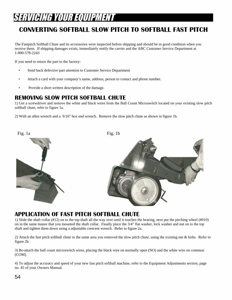
54
APPLICATION OF FAST PITCH SOFTBALL CHUTE 1) Slide the shaft collar (#12) on to the top shaft all the way over until it touches the bearing, next put the pitching wheel (#010) on in the same manor that you mounted the shaft collar. Finally place the 3/4” flat washer, lock washer and nut on to the top shaft and tighten them down using a adjustable crescent wrench. Refer to figure 2a. 2) Attach the fast pitch softball chute to the same area you removed the slow pitch chute, using the existing nut & bolts. Refer to figure 2b 3) Re-attach the ball count microswitch wires, placing the black wire on normally open (NO) and the white wire on common (COM). 4) To adjust the accuracy and speed of your new fast pitch softball machine, refer to the Equipment Adjustments section, page no. 45 of your Owners Manual.
CONVERTING SOFTBALL SLOW PITCH TO SOFTBALL FAST PITCH
The Fastpitch Softball Chute and its accessories were inspected before shipping and should be in good condition when you receive them. If shipping damages exists, immediately notify the carrier and the ABC Customer Service Department at 1-800-578-2243 If you need to return the part to the factory: • Send back defective part attention to Customer Service Department • Attach a card with your company’s name, address, person to contact and phone number. • Provide a short written description of the damage.
REMOVING SLOW PITCH SOFTBALL CHUTE 1) Get a screwdriver and remove the white and black wires from the Ball Count Microswitch located on your existing slow pitch softball chute, refer to figure 1a. 2) With an allen wrench and a 9/16” box end wrench. Remove the slow pitch chute as shown in figure 1b.
Fig. 1a Fig. 1b
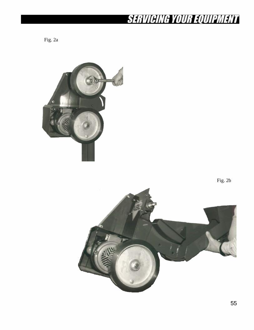
55
Fig. 2b
Fig. 2a
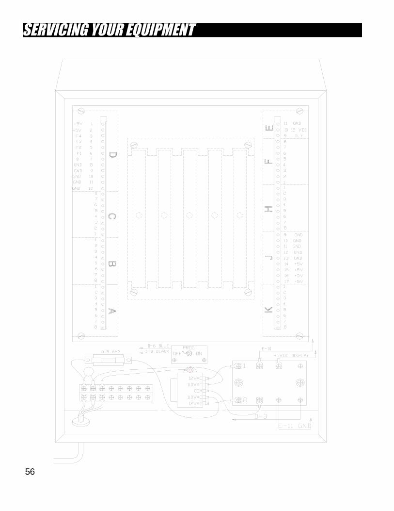
56
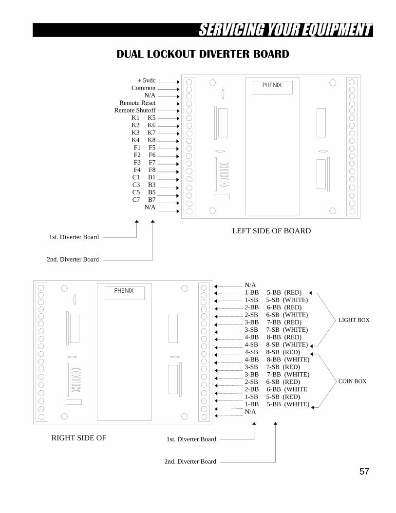
57
PHENIX
DUAL LOCKOUT DIVERTER BOARD
+ 5vdc Common
N/A Remote Reset
Remote Shutoff K1 K5 K2 K6 K3 K7 K4 K8 F1 F5 F2 F6 F3 F7 F4 F8 C1 B1 C3 B3 C5 B5 C7 B7
N/A
1st. Diverter Board
2nd. Diverter Board
PHENIX
1st. Diverter Board
2nd. Diverter Board
N/A 1-BB 5-BB (RED) 1-SB 5-SB (WHITE) 2-BB 6-BB (RED) 2-SB 6-SB (WHITE) 3-BB 7-BB (RED) 3-SB 7-SB (WHITE) 4-BB 8-BB (RED) 4-SB 8-SB (WHITE) 4-SB 8-SB (RED) 4-BB 8-BB (WHITE) 3-SB 7-SB (RED) 3-BB 7-BB (WHITE) 2-SB 6-SB (RED) 2-BB 6-BB (WHITE 1-SB 5-SB (RED) 1-BB 5-BB (WHITE) N/A
COIN BOX
LIGHT BOX
RIGHT SIDE OF
LEFT SIDE OF BOARD
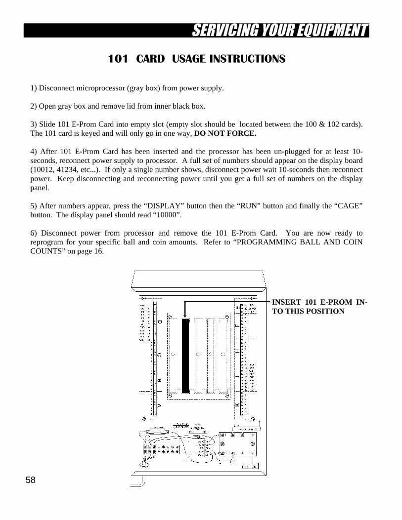
58
101 CARD USAGE INSTRUCTIONS 1) Disconnect microprocessor (gray box) from power supply. 2) Open gray box and remove lid from inner black box. 3) Slide 101 E-Prom Card into empty slot (empty slot should be located between the 100 & 102 cards). The 101 card is keyed and will only go in one way, DO NOT FORCE. 4) After 101 E-Prom Card has been inserted and the processor has been un-plugged for at least 10-seconds, reconnect power supply to processor. A full set of numbers should appear on the display board (10012, 41234, etc...). If only a single number shows, disconnect power wait 10-seconds then reconnect power. Keep disconnecting and reconnecting power until you get a full set of numbers on the display panel. 5) After numbers appear, press the “DISPLAY” button then the “RUN” button and finally the “CAGE” button. The display panel should read “10000”. 6) Disconnect power from processor and remove the 101 E-Prom Card. You are now ready to reprogram for your specific ball and coin amounts. Refer to “PROGRAMMING BALL AND COIN COUNTS” on page 16.
INSERT 101 E-PROM IN-TO THIS POSITION
59
DAILY OPERATIONAL
FORMS & CHECKLISTS
Pages 59 thru 68
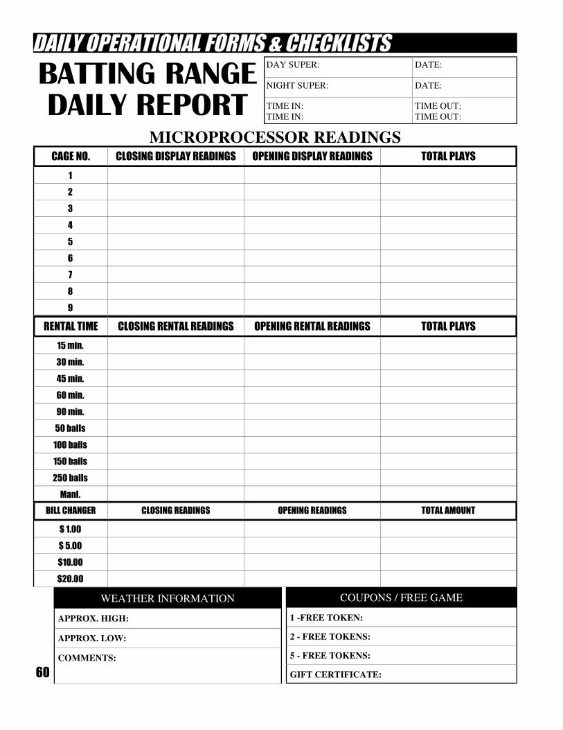
60
DAY SUPER: DATE:
NIGHT SUPER: DATE:
TIME IN:
TIME IN:
TIME OUT:
TIME OUT:
MICROPROCESSOR READINGS CAGE NO. CLOSING DISPLAY READINGS OPENING DISPLAY READINGS TOTAL PLAYS
1
2
3
4
5
6
7
8
9
WEATHER INFORMATION
APPROX. HIGH:
APPROX. LOW:
COMMENTS:
COUPONS / FREE GAME
1 -FREE TOKEN:
2 - FREE TOKENS:
5 - FREE TOKENS:
GIFT CERTIFICATE:
RENTAL TIME CLOSING RENTAL READINGS OPENING RENTAL READINGS TOTAL PLAYS
15 min.
30 min.
45 min.
60 min.
90 min.
50 balls
100 balls
150 balls
250 balls
Manl.
BILL CHANGER CLOSING READINGS OPENING READINGS TOTAL AMOUNT
$ 1.00
$ 5.00
$10.00
$20.00
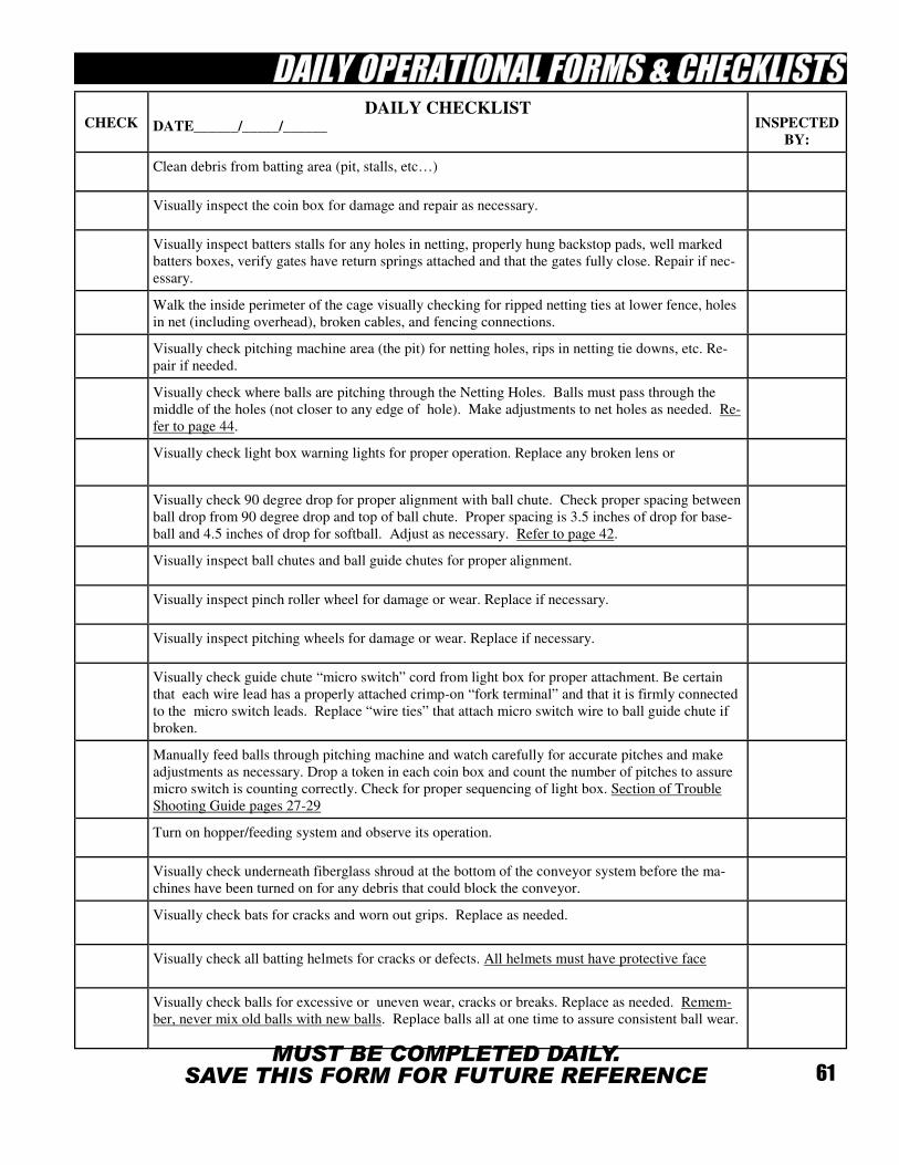
61
CHECK DAILY CHECKLIST
DATE______/_____/______
INSPECTED
BY:
Clean debris from batting area (pit, stalls, etc…)
Visually inspect the coin box for damage and repair as necessary.
Visually inspect batters stalls for any holes in netting, properly hung backstop pads, well marked
batters boxes, verify gates have return springs attached and that the gates fully close. Repair if nec-
essary.
Walk the inside perimeter of the cage visually checking for ripped netting ties at lower fence, holes
in net (including overhead), broken cables, and fencing connections.
Visually check pitching machine area (the pit) for netting holes, rips in netting tie downs, etc. Re-
pair if needed.
Visually check where balls are pitching through the Netting Holes. Balls must pass through the
middle of the holes (not closer to any edge of hole). Make adjustments to net holes as needed. Re-
fer to page 44.
Visually check light box warning lights for proper operation. Replace any broken lens or
Visually check 90 degree drop for proper alignment with ball chute. Check proper spacing between
ball drop from 90 degree drop and top of ball chute. Proper spacing is 3.5 inches of drop for base-
ball and 4.5 inches of drop for softball. Adjust as necessary. Refer to page 42.
Visually inspect ball chutes and ball guide chutes for proper alignment.
Visually inspect pinch roller wheel for damage or wear. Replace if necessary.
Visually inspect pitching wheels for damage or wear. Replace if necessary.
Visually check guide chute “micro switch” cord from light box for proper attachment. Be certain
that each wire lead has a properly attached crimp-on “fork terminal” and that it is firmly connected
to the micro switch leads. Replace “wire ties” that attach micro switch wire to ball guide chute if
broken.
Manually feed balls through pitching machine and watch carefully for accurate pitches and make
adjustments as necessary. Drop a token in each coin box and count the number of pitches to assure
micro switch is counting correctly. Check for proper sequencing of light box. Section of Trouble
Shooting Guide pages 27-29
Turn on hopper/feeding system and observe its operation.
Visually check underneath fiberglass shroud at the bottom of the conveyor system before the ma-
chines have been turned on for any debris that could block the conveyor.
Visually check bats for cracks and worn out grips. Replace as needed.
Visually check all batting helmets for cracks or defects. All helmets must have protective face
Visually check balls for excessive or uneven wear, cracks or breaks. Replace as needed. Remem-
ber, never mix old balls with new balls. Replace balls all at one time to assure consistent ball wear.
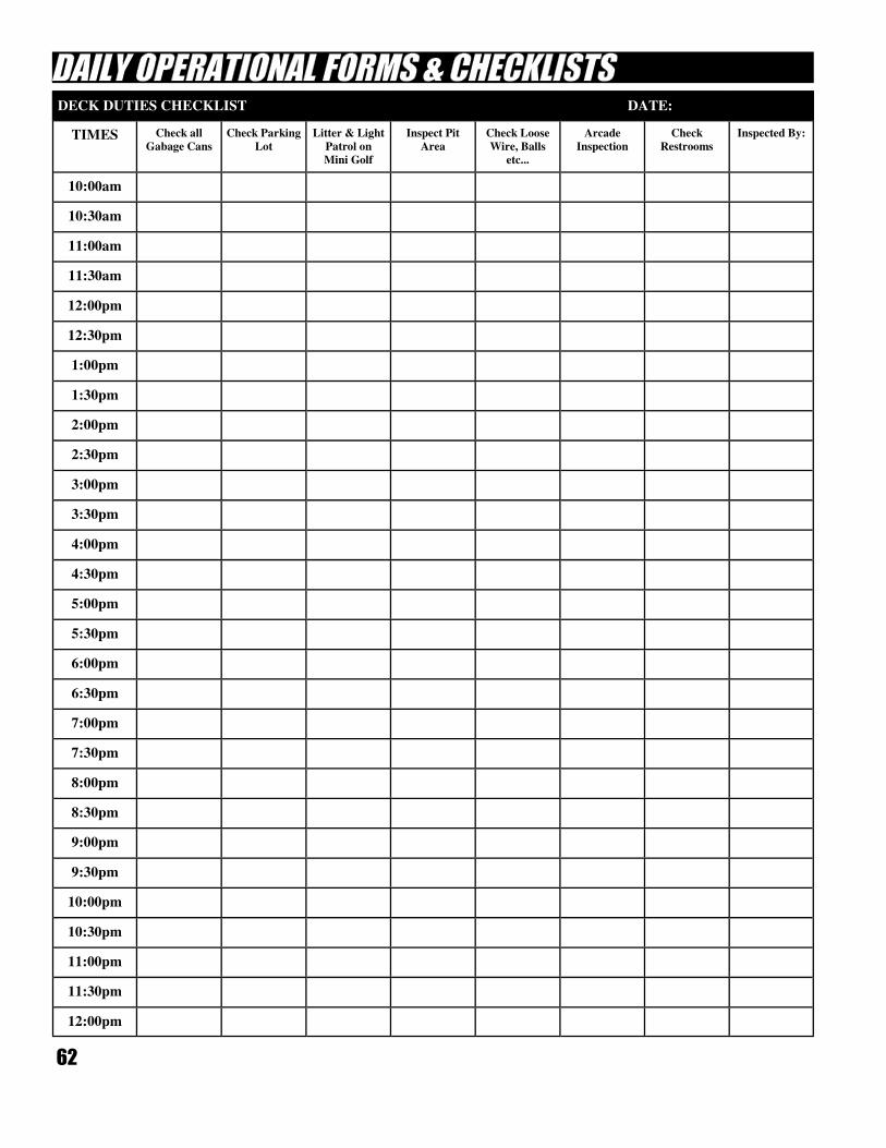
62
DECK DUTIES CHECKLIST DATE:
TIMES
Check all
Gabage Cans
Check Parking
Lot
Litter & Light
Patrol on
Mini Golf
Inspect Pit
Area
Check Loose
Wire, Balls
etc...
Arcade
Inspection
Check
Restrooms
Inspected By:
10:00am
10:30am
11:00am
11:30am
12:00pm
12:30pm
1:00pm
1:30pm
2:00pm
2:30pm
3:00pm
3:30pm
4:00pm
4:30pm
5:00pm
5:30pm
6:00pm
6:30pm
7:00pm
7:30pm
8:00pm
8:30pm
9:00pm
9:30pm
10:00pm
10:30pm
11:00pm
11:30pm
12:00pm
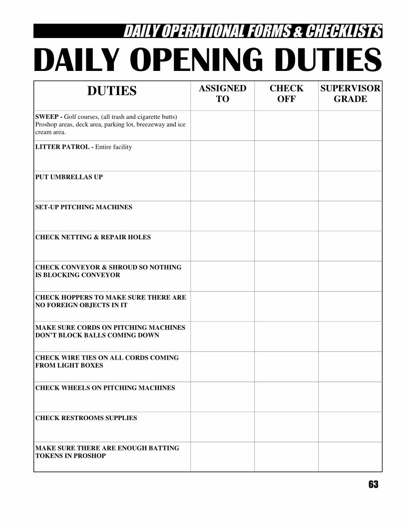
63
DUTIES ASSIGNED
TO
CHECK
OFF
SUPERVISOR
GRADE
SWEEP - Golf courses, (all trash and cigarette butts)
Proshop areas, deck area, parking lot, breezeway and ice
cream area.
LITTER PATROL - Entire facility
PUT UMBRELLAS UP
SET-UP PITCHING MACHINES
CHECK NETTING & REPAIR HOLES
CHECK CONVEYOR & SHROUD SO NOTHING
IS BLOCKING CONVEYOR
CHECK HOPPERS TO MAKE SURE THERE ARE
NO FOREIGN OBJECTS IN IT
MAKE SURE CORDS ON PITCHING MACHINES
DON’T BLOCK BALLS COMING DOWN
CHECK WIRE TIES ON ALL CORDS COMING
FROM LIGHT BOXES
CHECK WHEELS ON PITCHING MACHINES
CHECK RESTROOMS SUPPLIES
MAKE SURE THERE ARE ENOUGH BATTING
TOKENS IN PROSHOP
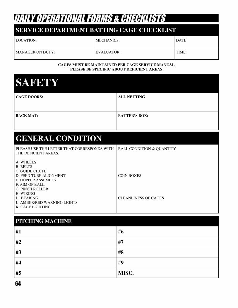
64
LOCATION: MECHANICS: DATE:
MANAGER ON DUTY: EVALUATOR: TIME:
SERVICE DEPARTMENT BATTING CAGE CHECKLIST
CAGES MUST BE MAINTAINED PER CAGE SERVICE MANUAL
PLEASE BE SPECIFIC ABOUT DEFICIENT AREAS
CAGE DOORS: ALL NETTING
BACK MAT: BATTER’S BOX:
SAFETY
PLEASE USE THE LETTER THAT CORRESPONDS WITH
THE DEFICIENT AREAS.
A. WHEELS
B. BELTS
C. GUIDE CHUTE
D. FEED TUBE ALIGNMENT
E. HOPPER ASSEMBLY
F. AIM OF BALL
G. PINCH ROLLER
H. WIRING
I. BEARING
J. AMBER/RED WARNING LIGHTS
K. CAGE LIGHTING
BALL CONDITION & QUANTITY
COIN BOXES
CLEANLINESS OF CAGES
GENERAL CONDITION
#1 #6
#2 #7
#3 #8
#4 #9
#5 MISC.
PITCHING MACHINE
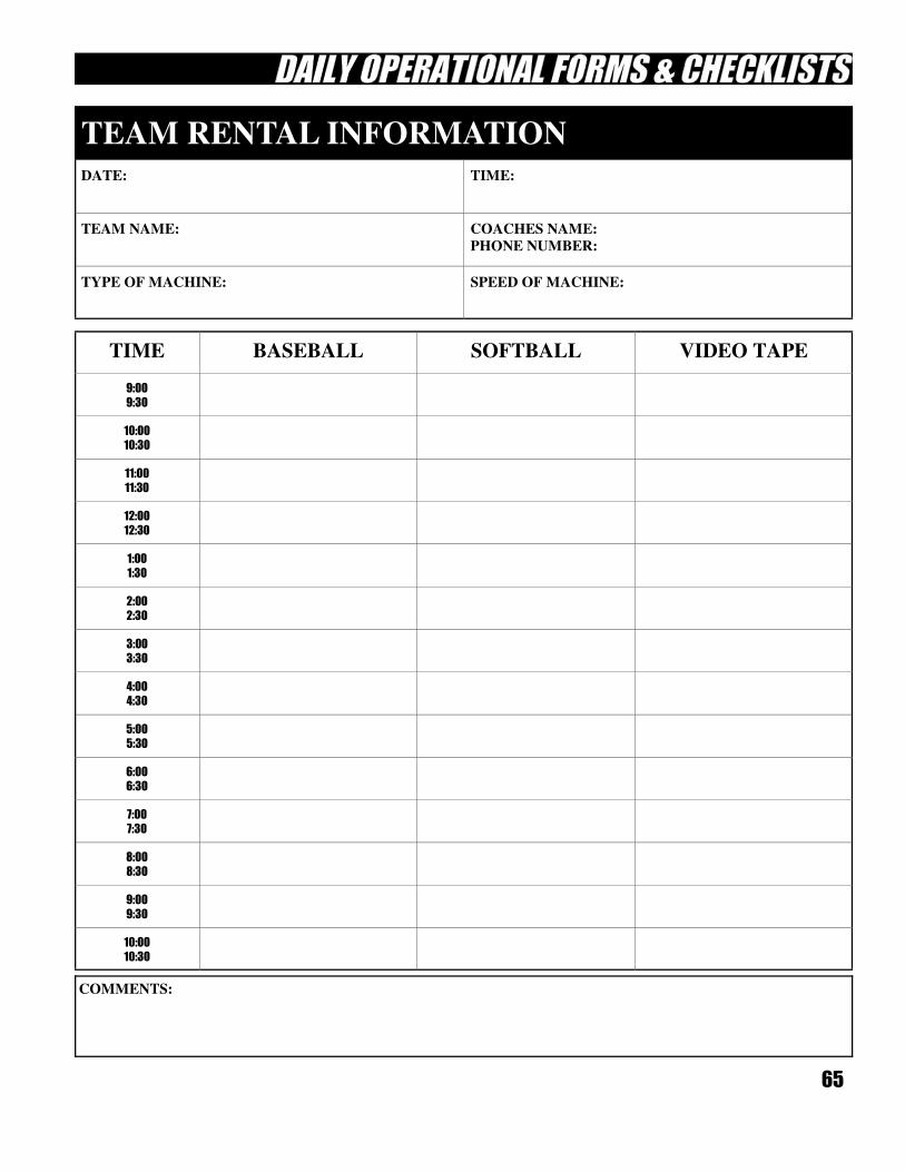
65
DATE: TIME:
TEAM NAME: COACHES NAME:
PHONE NUMBER:
TYPE OF MACHINE: SPEED OF MACHINE:
TEAM RENTAL INFORMATION
TIME BASEBALL SOFTBALL VIDEO TAPE
9:00 9:30
10:00 10:30
11:00 11:30
12:00 12:30
1:00 1:30
2:00 2:30
3:00 3:30
4:00 4:30
5:00 5:30
6:00 6:30
7:00 7:30
8:00 8:30
9:00 9:30
10:00 10:30
COMMENTS:
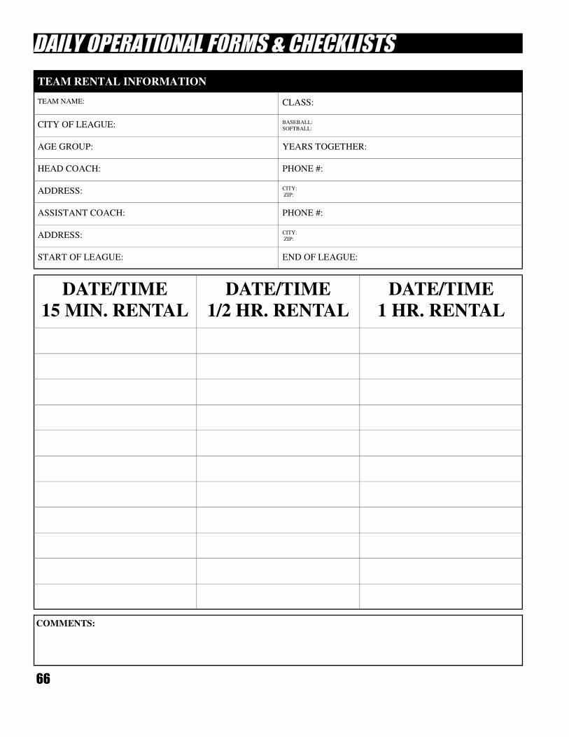
66
TEAM NAME: CLASS:
CITY OF LEAGUE: BASEBALL:
SOFTBALL:
AGE GROUP: YEARS TOGETHER:
HEAD COACH: PHONE #:
ADDRESS: CITY:
ZIP:
ASSISTANT COACH: PHONE #:
ADDRESS: CITY:
ZIP:
START OF LEAGUE: END OF LEAGUE:
TEAM RENTAL INFORMATION
COMMENTS:
DATE/TIME
15 MIN. RENTAL
DATE/TIME
1/2 HR. RENTAL
DATE/TIME
1 HR. RENTAL
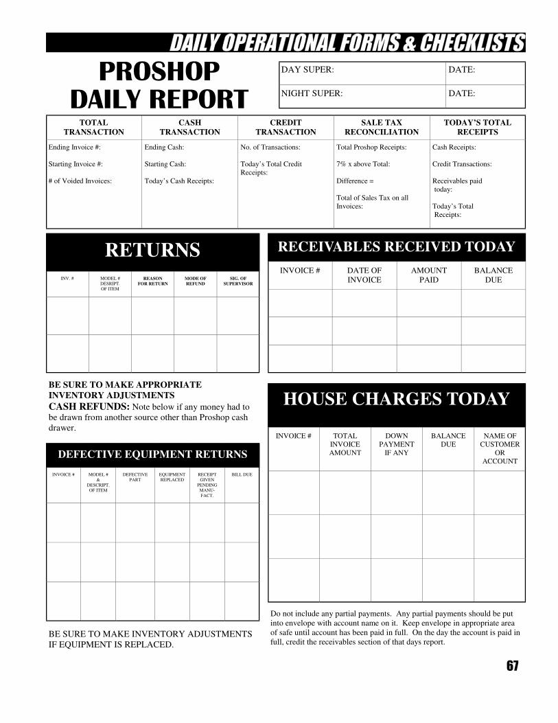
67
DAY SUPER: DATE:
NIGHT SUPER: DATE:
TOTAL
TRANSACTION CASH
TRANSACTION CREDIT
TRANSACTION SALE TAX
RECONCILIATION TODAY’S TOTAL
RECEIPTS
Ending Invoice #:
Starting Invoice #:
# of Voided Invoices:
Ending Cash:
Starting Cash:
Today’s Cash Receipts:
No. of Transactions:
Today’s Total Credit
Receipts:
Total Proshop Receipts:
7% x above Total:
Difference =
Total of Sales Tax on all
Invoices:
Cash Receipts:
Credit Transactions:
Receivables paid
today:
Today’s Total
Receipts:
INV. # MODEL #
DESRIPT.
OF ITEM
REASON
FOR RETURN MODE OF
REFUND SIG. OF
SUPERVISOR
RETURNS
INVOICE # DATE OF
INVOICE AMOUNT
PAID BALANCE
DUE
RECEIVABLES RECEIVED TODAY
BE SURE TO MAKE APPROPRIATE
INVENTORY ADJUSTMENTS
CASH REFUNDS: Note below if any money had to
be drawn from another source other than Proshop cash
drawer.
BE SURE TO MAKE INVENTORY ADJUSTMENTS
IF EQUIPMENT IS REPLACED.
INVOICE # MODEL #
&
DESCRIPT.
OF ITEM
DEFECTIVE
PART EQUIPMENT
REPLACED RECEIPT
GIVEN
PENDING
MANU-
FACT.
BILL DUE
DEFECTIVE EQUIPMENT RETURNS
Do not include any partial payments. Any partial payments should be put
into envelope with account name on it. Keep envelope in appropriate area
of safe until account has been paid in full. On the day the account is paid in
full, credit the receivables section of that days report.
INVOICE # TOTAL
INVOICE
AMOUNT
DOWN
PAYMENT
IF ANY
BALANCE
DUE NAME OF
CUSTOMER
OR
ACCOUNT
HOUSE CHARGES TODAY
68
QUANTITY PART NUMBER DESCRIPTION
SOLD TO:
NAME:
PHONE #:
P.O. #:
SHIP TO:
NAME:
PHONE #:
P.O. #:
SPECIAL INSTRUCTIONS:
UPS REGULAR UPS 3RD DAY UPS BLUE UPS RED UPS RED SATURDAY
CHECK ONE ONLY
69
OPERATION OF BALL DRYERS
Pages 69 thru 73
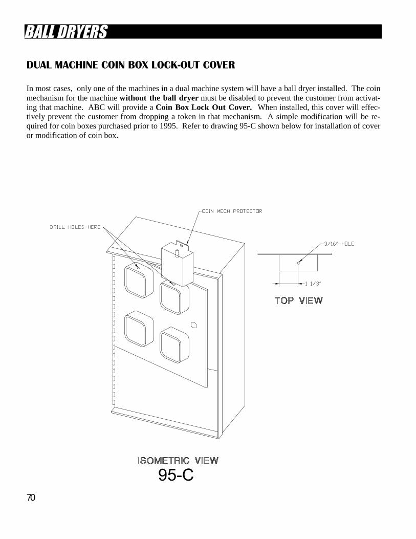
70
DUAL MACHINE COIN BOX LOCK-OUT COVER In most cases, only one of the machines in a dual machine system will have a ball dryer installed. The coin mechanism for the machine without the ball dryer must be disabled to prevent the customer from activat-ing that machine. ABC will provide a Coin Box Lock Out Cover. When installed, this cover will effec-tively prevent the customer from dropping a token in that mechanism. A simple modification will be re-quired for coin boxes purchased prior to 1995. Refer to drawing 95-C shown below for installation of cover or modification of coin box.
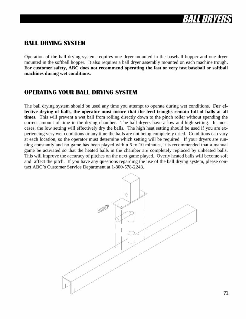
71
BALL DRYING SYSTEM Operation of the ball drying system requires one dryer mounted in the baseball hopper and one dryer mounted in the softball hopper. It also requires a ball dryer assembly mounted on each machine trough. For customer safety, ABC does not recommend operating the fast or very fast baseball or softball machines during wet conditions. OPERATING YOUR BALL DRYING SYSTEM The ball drying system should be used any time you attempt to operate during wet conditions. For ef-fective drying of balls, the operator must insure that the feed troughs remain full of balls at all times. This will prevent a wet ball from rolling directly down to the pinch roller without spending the correct amount of time in the drying chamber. The ball dryers have a low and high setting. In most cases, the low setting will effectively dry the balls. The high heat setting should be used if you are ex-periencing very wet conditions or any time the balls are not being completely dried. Conditions can vary at each location, so the operator must determine which setting will be required. If your dryers are run-ning constantly and no game has been played within 5 to 10 minutes, it is recommended that a manual game be activated so that the heated balls in the chamber are completely replaced by unheated balls. This will improve the accuracy of pitches on the next game played. Overly heated balls will become soft and affect the pitch. If you have any questions regarding the use of the ball drying system, please con-tact ABC’s Customer Service Department at 1-800-578-2243.
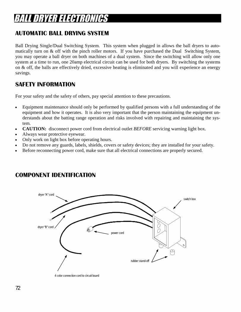
72
AUTOMATIC BALL DRYING SYSTEM Ball Drying Single/Dual Switching System. This system when plugged in allows the ball dryers to auto-matically turn on & off with the pinch roller motors. If you have purchased the Dual Switching System, you may operate a ball dryer on both machines of a dual system. Since the switching will allow only one system at a time to run, one 20amp electrical circuit can be used for both dryers. By switching the systems on & off, the balls are effectively dried, excessive heating is eliminated and you will experience an energy savings.
SAFETY INFORMATION For your safety and the safety of others, pay special attention to these precautions. • Equipment maintenance should only be performed by qualified persons with a full understanding of the
equipment and how it operates. It is also very important that the person maintaining the equipment un-derstands about the batting range operation and risks involved with repairing and maintaining the sys-tem.
• CAUTION: disconnect power cord from electrical outlet BEFORE servicing warning light box. • Always wear protective eyewear. • Only work on light box before operating hours. • Do not remove any guards, labels, shields, covers or safety devices; they are installed for your safety. • Before reconnecting power cord, make sure that all electrical connections are properly secured.
COMPONENT IDENTIFICATION
switch box
rubber stand-off
power cord
4 color connection cord to circuit board
dryer “B” cord
dryer “A” cord
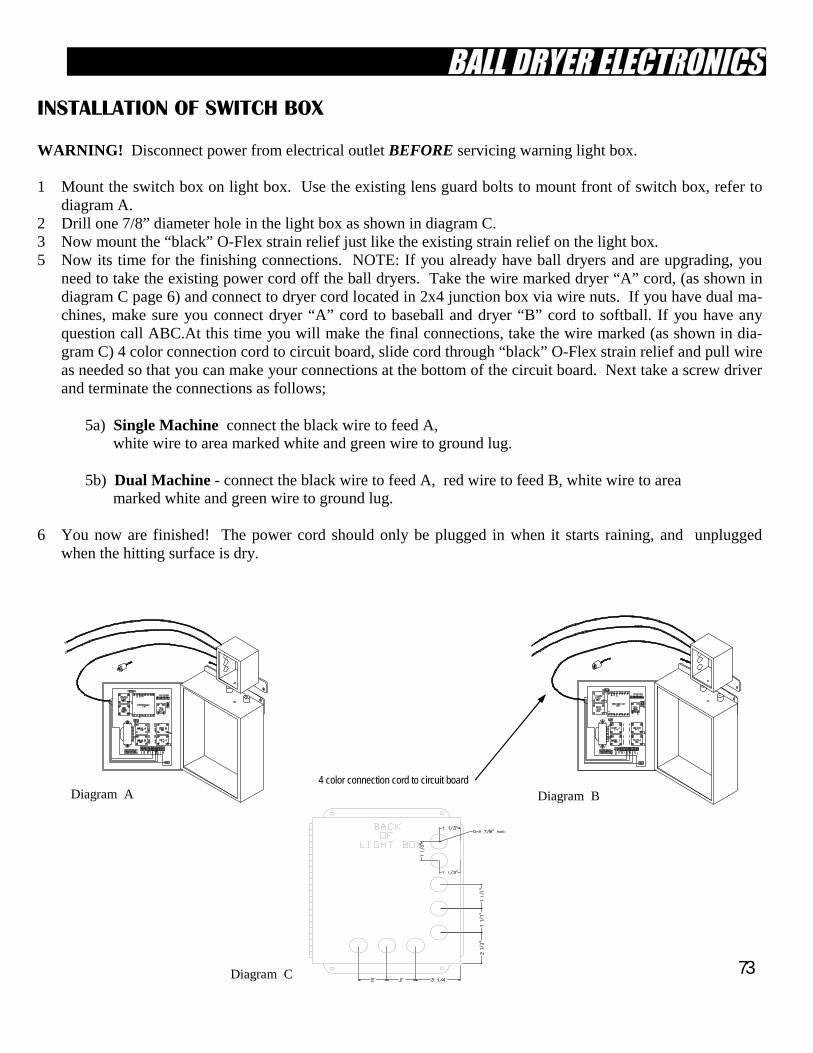
73
INSTALLATION OF SWITCH BOX WARNING! Disconnect power from electrical outlet BEFORE servicing warning light box. 1 Mount the switch box on light box. Use the existing lens guard bolts to mount front of switch box, refer to
diagram A. 2 Drill one 7/8” diameter hole in the light box as shown in diagram C. 3 Now mount the “black” O-Flex strain relief just like the existing strain relief on the light box. 5 Now its time for the finishing connections. NOTE: If you already have ball dryers and are upgrading, you
need to take the existing power cord off the ball dryers. Take the wire marked dryer “A” cord, (as shown in diagram C page 6) and connect to dryer cord located in 2x4 junction box via wire nuts. If you have dual ma-chines, make sure you connect dryer “A” cord to baseball and dryer “B” cord to softball. If you have any question call ABC.At this time you will make the final connections, take the wire marked (as shown in dia-gram C) 4 color connection cord to circuit board, slide cord through “black” O-Flex strain relief and pull wire as needed so that you can make your connections at the bottom of the circuit board. Next take a screw driver and terminate the connections as follows;
5a) Single Machine connect the black wire to feed A, white wire to area marked white and green wire to ground lug. 5b) Dual Machine - connect the black wire to feed A, red wire to feed B, white wire to area marked white and green wire to ground lug. 6 You now are finished! The power cord should only be plugged in when it starts raining, and unplugged
when the hitting surface is dry.
Diagram A 4 color connection cord to circuit board
Diagram C
Diagram B
74
SELECT-A-PITCH SYSTEM
Pages 74 thru 89
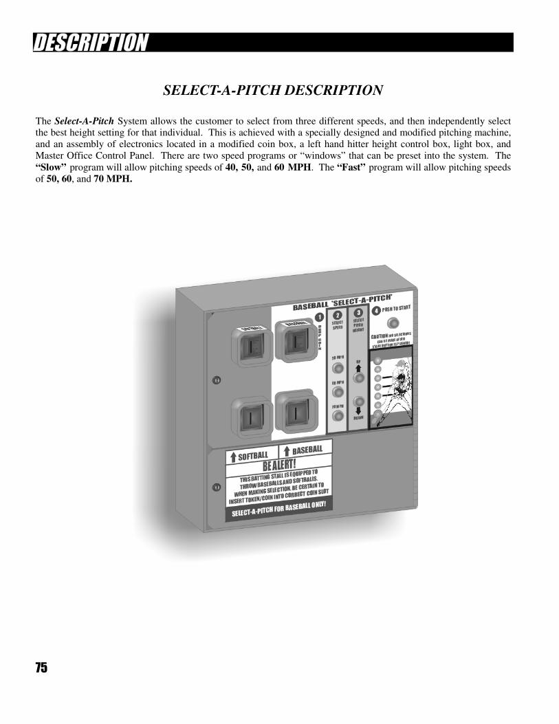
75
SELECT-A-PITCH DESCRIPTION
The Select-A-Pitch System allows the customer to select from three different speeds, and then independently select the best height setting for that individual. This is achieved with a specially designed and modified pitching machine,
and an assembly of electronics located in a modified coin box, a left hand hitter height control box, light box, and
Master Office Control Panel. There are two speed programs or “windows” that can be preset into the system. The
“Slow” program will allow pitching speeds of 40, 50, and 60 MPH. The “Fast” program will allow pitching speeds
of 50, 60, and 70 MPH.
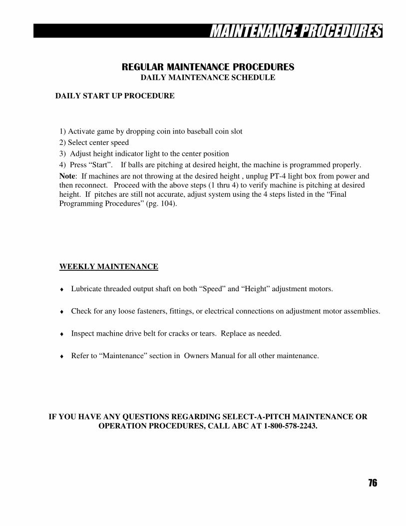
76
REGULAR MAINTENANCE PROCEDURES
DAILY MAINTENANCE SCHEDULE
DAILY START UP PROCEDURE
IF YOU HAVE ANY QUESTIONS REGARDING SELECT-A-PITCH MAINTENANCE OR
OPERATION PROCEDURES, CALL ABC AT 1-800-578-2243.
1) Activate game by dropping coin into baseball coin slot
2) Select center speed
3) Adjust height indicator light to the center position
4) Press “Start”. If balls are pitching at desired height, the machine is programmed properly.
Note: If machines are not throwing at the desired height , unplug PT-4 light box from power and then reconnect. Proceed with the above steps (1 thru 4) to verify machine is pitching at desired
height. If pitches are still not accurate, adjust system using the 4 steps listed in the “Final
Programming Procedures” (pg. 104).
WEEKLY MAINTENANCE
♦ Lubricate threaded output shaft on both “Speed” and “Height” adjustment motors.
♦ Check for any loose fasteners, fittings, or electrical connections on adjustment motor assemblies.
♦ Inspect machine drive belt for cracks or tears. Replace as needed.
♦ Refer to “Maintenance” section in Owners Manual for all other maintenance.
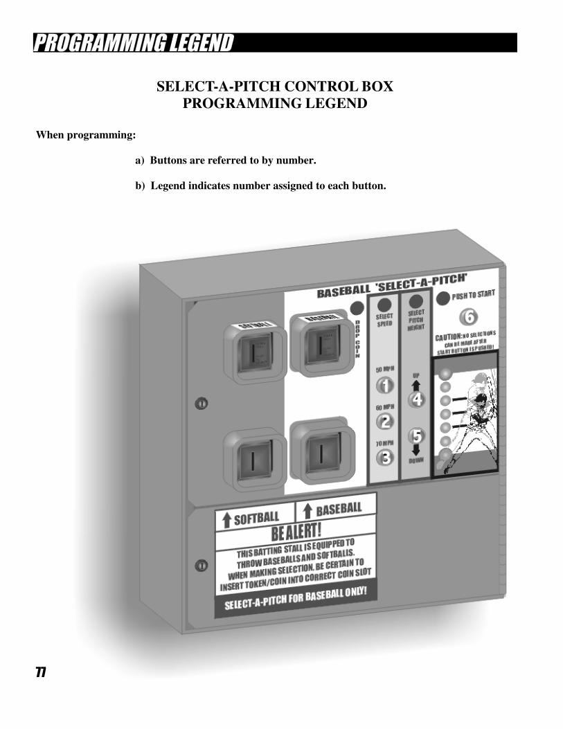
77
SELECT-A-PITCH CONTROL BOX
PROGRAMMING LEGEND
When programming:
a) Buttons are referred to by number.
b) Legend indicates number assigned to each button.
78
SELECT-A-PITCH MECHANICAL INITIALIZATION PROCEDURE
This procedure must be performed when the system is first installed or if a new elevation motor assembly is
installed on the pitching machine.
1) Connect light box and Master Office Control Panel to power (115VAC).
2) The mechanical initialization must be performed using the speed program that the machine will
be operated at. “Slow” program (40, 50, 60 MPH) or “Fast” program (50, 60, 70 MPH). Any cus-
tom speed adjustments must be performed after step 5.
3) Enter the factory speed preset. Press “Program Switch” 4, 5, 1 for “Slow” program or “Program Switch” 4, 5, 2 for “Fast” program.
4) Enter factory elevation preset by pressing Program Switch 4, 5, 3 and then Program Switch 4, 2, 6 to
save.
5) Cycle A/C power. Unplug light box from power (115VAC) and reconnect. Elevation motor will move
backwards to stops and then reverse and move forward 10 revolutions.
6) OPTIONAL : Adjust custom speeds at this stage if necessary.
7) Start game at coin panel and select center speed. LED will be at center position. Push “Start” button
and observe pitch height. Pitches must be at adult waist level. If pitch is too low you must move locking collar (on elevation motor shaft) back towards motor. If pitch is too high you must move lock-
ing collar forward (away from motor). After every adjustment you must unplug the light box and then
plug it back in. This allows the elevation motor to relocate itself. Continue to make locking collar ad-
justments until pitches are at the adult waist level.
8) Once the pitches are within this range press Program Switch 4, 6, 1, then Program Switch 4, 6, 2 , then
Program Switch 4, 6, 3.
9) Press “Program Switch” 5, 1
10) Press “Program Switch” 5, 3 to activate game. Select center speed and press “Start”. Confirm that
ball is being pitched at adult waist height and LED is in center position. If not, mechanical initialization
procedure must be repeated.
11) Press “Program Switch” 5, 1 to stop game. Mechanical initialization is complete. You may now pro-
ceed to the Final Programming Procedure.
79
TROUBLESHOOTING SUGGESTIONS
Troubleshooting problems with the Select-A-Pitch system will require an understanding of how the system operates.
Review the “Power Flow” charts, which indicate the voltage that the different color wires will carry, component
drawings for location of voltage, LED indicator lights which shows if voltage is present, and the “Sequence of Opera-
tion”. It is very important to observe the sequence of operation and take note of what is not happening or what is out
of sequence. This will enable you to understand how the system works and direct you to the specific problem area.
Using the various charts will enable you to check for proper voltage at specific locations. When proper voltages are
present, a defective component is likely. If proper voltage is not present, trace the power flow back until you locate
the origin of voltage loss. Please call ABC Customer Service with your results or if you require any assistance.
SELECT-A-PITCH
FINAL PROGRAMMING PROCEDURE
These programming steps are to be performed after the mechanical initialization is complete. You will also
use these simple programming steps to correct minor errors or glitches that may occur during normal opera-
tion of the Select-A-Pitch System. See Select-A-Pitch Troubleshooting section for assistance.
1) Press “Program Switch” 5, 3 to activate game. Select “Slow” speed and push “Start”. Adjust
height of pitch to adult waist level by using “Up/Down” buttons only. Do not adjust height in
program mode.
2) Press “Program Switch” 4, 6. Using “Up/Down” buttons, move LED to center position. Press switch # 1 to save.
3) Press ”Program Switch” 5, 3 to activate game. Select “Fast” speed and push “Start”. Adjust
height of pitch to adult waist level by using “Up/Down” buttons only. Do not adjust height in
program mode.
4) Press “Program Switch” 4, 6. Using “Up/Down” buttons, move LED to center position. Press switch # 3 to save.
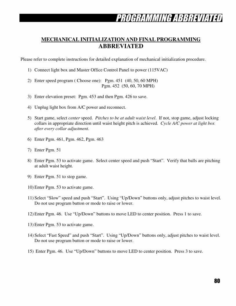
80
MECHANICAL INITIALIZATION AND FINAL PROGRAMMING
ABBREVIATED
Please refer to complete instructions for detailed explanation of mechanical initialization procedure.
1) Connect light box and Master Office Control Panel to power (115VAC)
2) Enter speed program ( Choose one): Pgm. 451 (40, 50, 60 MPH)
Pgm. 452 (50, 60, 70 MPH)
3) Enter elevation preset: Pgm. 453 and then Pgm. 426 to save.
4) Unplug light box from A/C power and reconnect.
5) Start game, select center speed. Pitches to be at adult waist level. If not, stop game, adjust locking
collars in appropriate direction until waist height pitch is achieved. Cycle A/C power at light box
after every collar adjustment.
6) Enter Pgm. 461, Pgm. 462, Pgm. 463
7) Enter Pgm. 51
8) Enter Pgm. 53 to activate game. Select center speed and push “Start”. Verify that balls are pitching
at adult waist height.
9) Enter Pgm. 51 to stop game.
10) Enter Pgm. 53 to activate game.
11) Select “Slow” speed and push “Start”. Using “Up/Down” buttons only, adjust pitches to waist level.
Do not use program button or mode to raise or lower.
12) Enter Pgm. 46. Use “Up/Down” buttons to move LED to center position. Press 1 to save.
13) Enter Pgm. 53 to activate game.
14) Select “Fast Speed” and push “Start”. Using “Up/Down” buttons only, adjust pitches to waist level.
Do not use program button or mode to raise or lower.
15) Enter Pgm. 46. Use “Up/Down” buttons to move LED to center position. Press 3 to save.
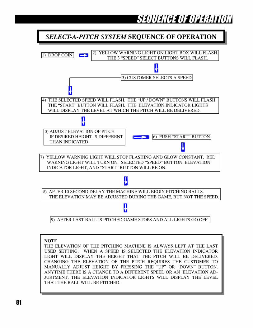
81
SELECT-A-PITCH SYSTEM SEQUENCE OF OPERATION
8) AFTER 10 SECOND DELAY THE MACHINE WILL BEGIN PITCHING BALLS.
THE ELEVATION MAY BE ADJUSTED DURING THE GAME, BUT NOT THE SPEED.
9) AFTER LAST BALL IS PITCHED GAME STOPS AND ALL LIGHTS GO OFF
7) YELLOW WARNING LIGHT WILL STOP FLASHING AND GLOW CONSTANT. RED
WARNING LIGHT WILL TURN ON. SELECTED “SPEED” BUTTON, ELEVATION
INDICATOR LIGHT, AND “START” BUTTON WILL BE ON.
5) ADJUST ELEVATION OF PITCH
IF DESIRED HEIGHT IS DIFFERENT
THAN INDICATED. 6) PUSH “START” BUTTON
4) THE SELECTED SPEED WILL FLASH. THE “UP / DOWN” BUTTONS WILL FLASH.
THE “START” BUTTON WILL FLASH. THE ELEVATION INDICATOR LIGHTS
WILL DISPLAY THE LEVEL AT WHICH THE PITCH WILL BE DELIVERED.
2) YELLOW WARNING LIGHT ON LIGHT BOX WILL FLASH.
THE 3 “SPEED” SELECT BUTTONS WILL FLASH. 1) DROP COIN
3) CUSTOMER SELECTS A SPEED
NOTE THE ELEVATION OF THE PITCHING MACHINE IS ALWAYS LEFT AT THE LAST
USED SETTING. WHEN A SPEED IS SELECTED THE ELEVATION INDICATOR
LIGHT WILL DISPLAY THE HEIGHT THAT THE PITCH WILL BE DELIVERED.
CHANGING THE ELEVATION OF THE PITCH REQUIRES THE CUSTOMER TO
MANUALLY ADJUST HEIGHT BY PRESSING THE “UP” OR “DOWN” BUTTON.
ANYTIME THERE IS A CHANGE TO A DIFFERENT SPEED OR AN ELEVATION AD-
JUSTMENT, THE ELEVATION INDICATOR LIGHTS WILL DISPLAY THE LEVEL
THAT THE BALL WILL BE PITCHED.
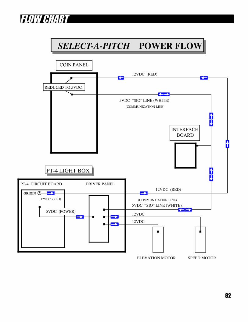
82
ORIGIN
12VDC (RED)
12VDC (RED)
PT-4 LIGHT BOX
PT-4 CIRCUIT BOARD DRIVER PANEL
COIN PANEL
INTERFACE
BOARD
5VDC (POWER)
REDUCED TO 5VDC
12VDC
12VDC
ELEVATION MOTOR SPEED MOTOR
SELECT-A-PITCH POWER FLOW
12VDC (RED)
5VDC “SIO” LINE (WHITE)
(COMMUNICATION LINE)
5VDC “SIO” LINE (WHITE)
(COMMUNICATION LINE)
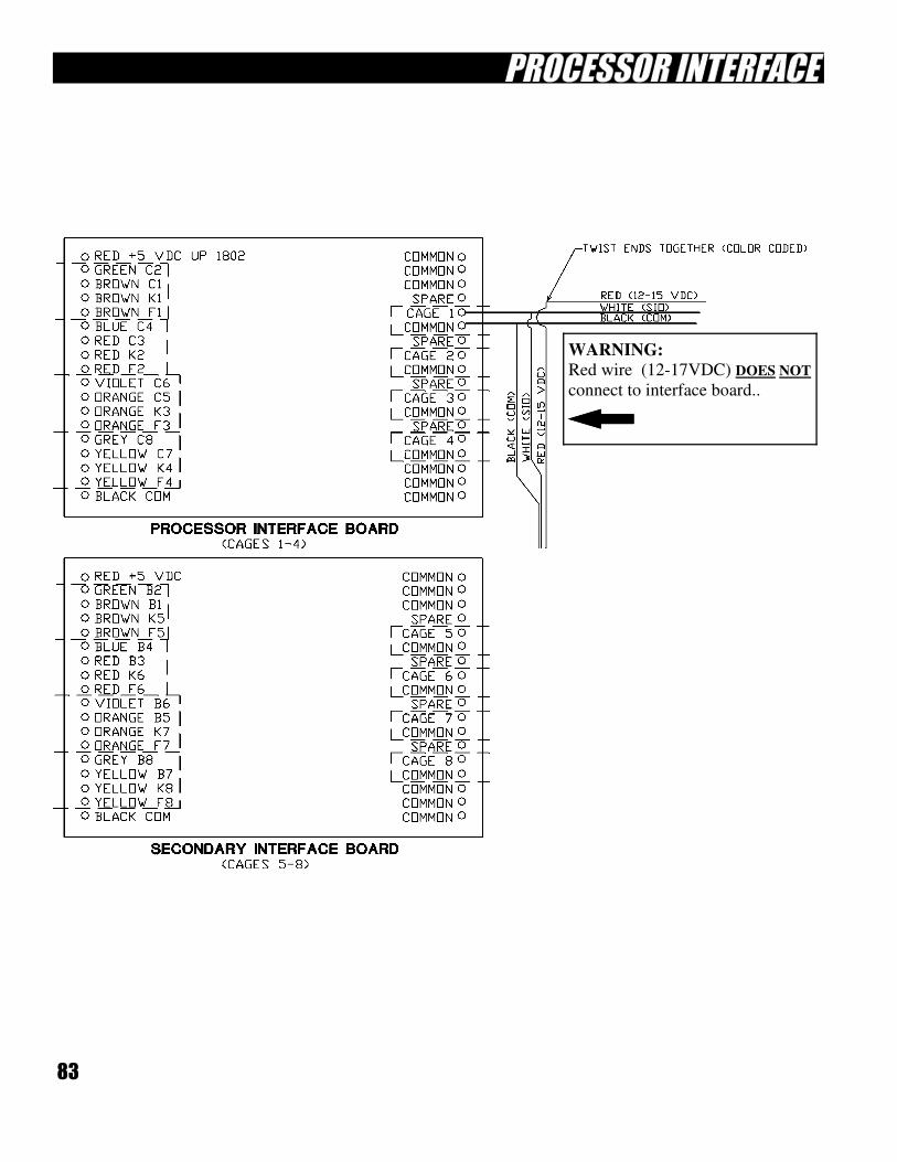
83
WARNING:
Red wire (12-17VDC) DOES NOT
connect to interface board..
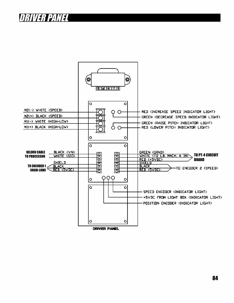
84
TO PT-4 CIRCUIT
BOARD
BELDEN CABLE
TO PROCESSOR
TO ENCODER 1
(HIGH-LOW)
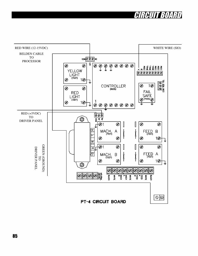
85
RED WIRE (12-15VDC) WHITE WIRE (SIO)
RED (+5VDC)
TO
DRIVER PANEL
GR
EE
N (G
RO
UN
D)
TO
DR
IVE
R P
AN
EL
BELDEN CABLE
TO
PROCESSOR
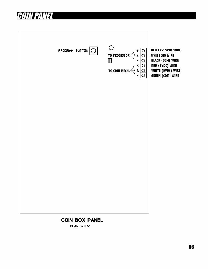
86
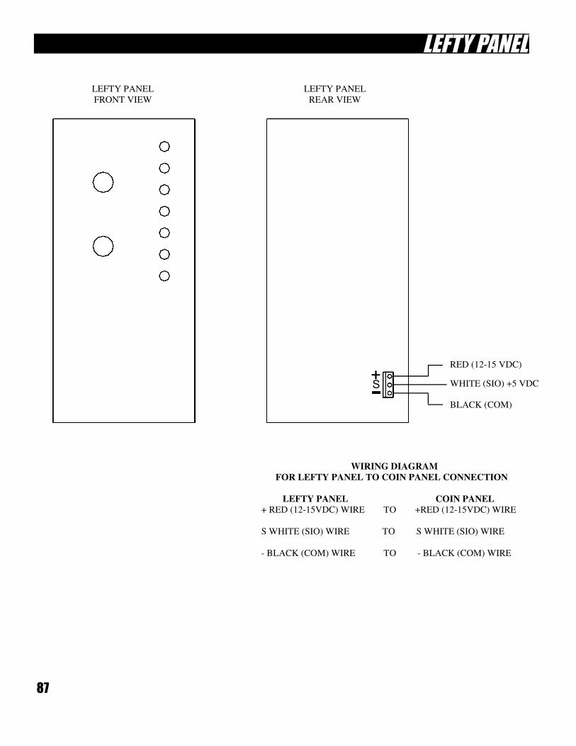
87
LEFTY PANEL
FRONT VIEW
LEFTY PANEL
REAR VIEW
RED (12-15 VDC)
WHITE (SIO) +5 VDC
BLACK (COM)
WIRING DIAGRAM
FOR LEFTY PANEL TO COIN PANEL CONNECTION
LEFTY PANEL COIN PANEL
+ RED (12-15VDC) WIRE TO +RED (12-15VDC) WIRE
S WHITE (SIO) WIRE TO S WHITE (SIO) WIRE
- BLACK (COM) WIRE TO - BLACK (COM) WIRE
88
SELECT-A-PITCH
SPEED ADJUSTMENT
1) Drop token to activate game (Note: activate 2-3 games to give you enough time)
2) Select “SPEED” (Button 1,2 or 3)
40 or 50mph = 1
50 or 60mph = 2
60 or 70mph = 3
3) Push Start
4) Push “Program Switch – 5 – 6”
5) Use button #4 (����) to increase speed
Use button #5 (����) to decrease speed
6) To save setting, push the same speed button that you selected in step 2)
7) Reprogram each speed. (40-50-60) or (50-60-70) following steps 1 through 7
8) If height needs to be adjusted, follow Initial setup procedures on page 104 in your ABC
Operation and Technical Manual.

89
90
CENTER POLE WINCH & COLLAR
Pages 90 thru 113
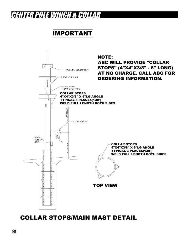
91
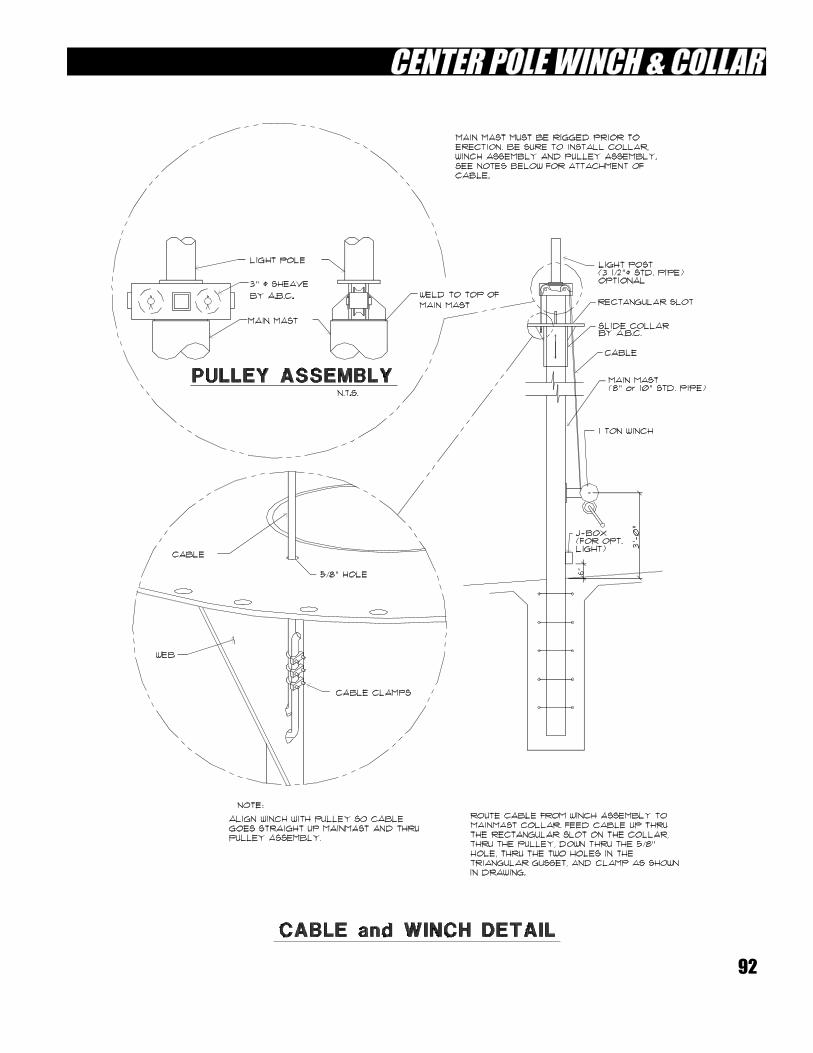
92
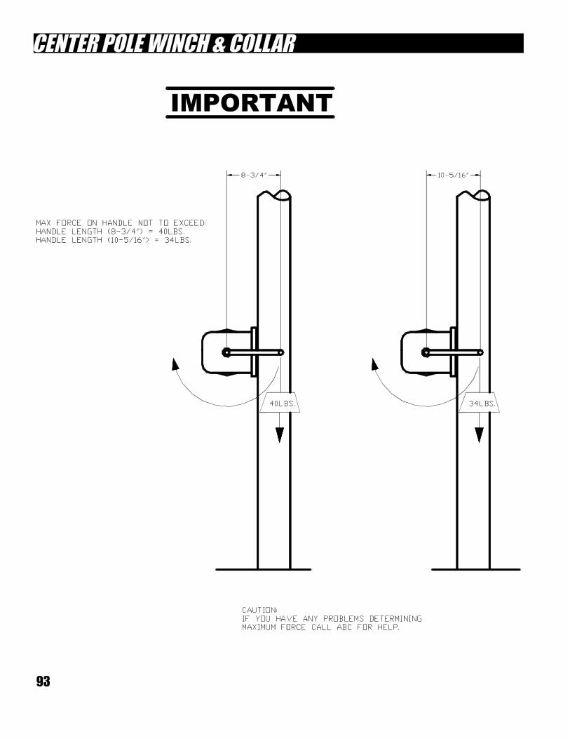
93
94
95
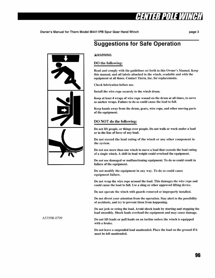
96
A5359B-0799
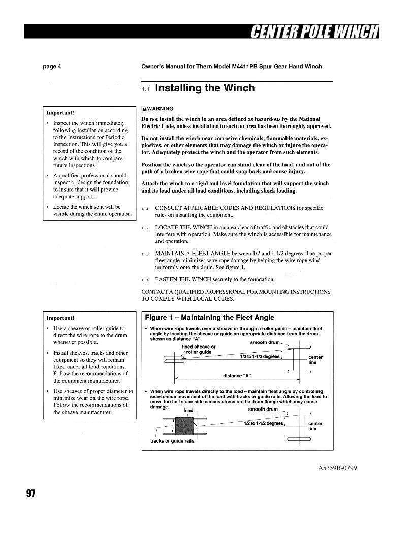
97
A5359B-0799
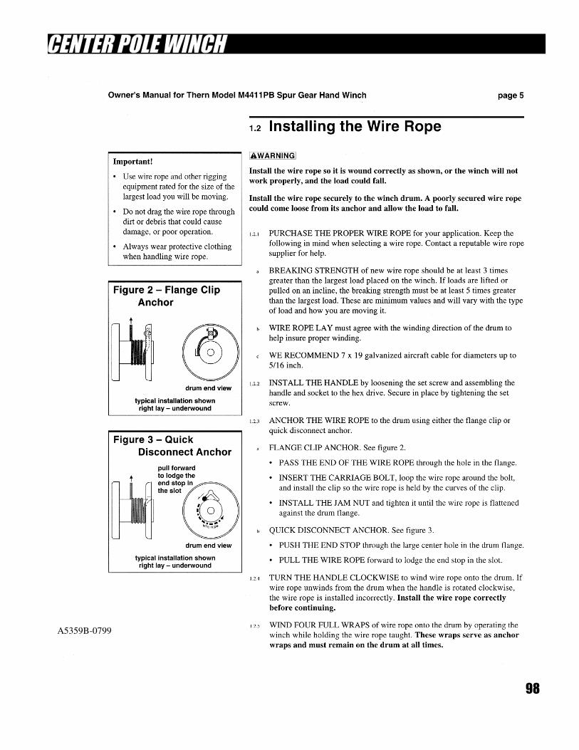
98
A5359B-0799
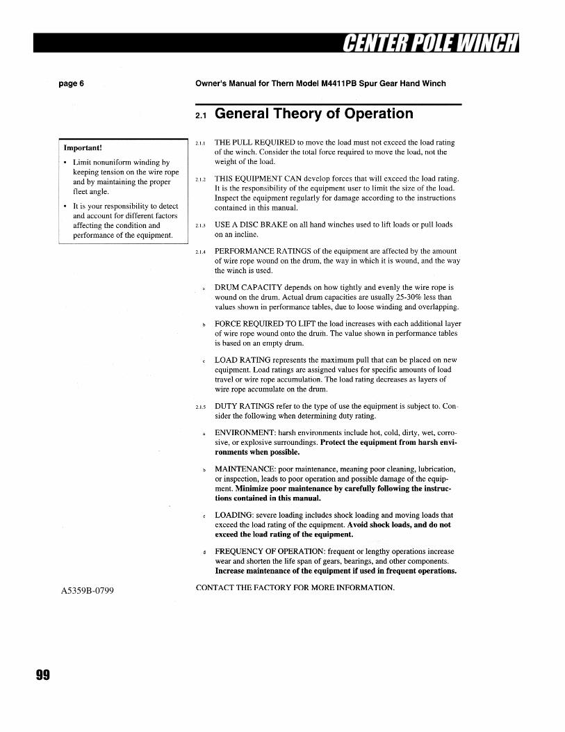
99
A5359B-0799
100
A5359B-0799
101
A5359B-0799
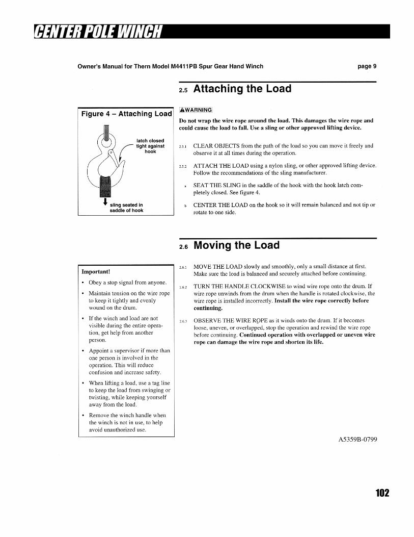
102
A5359B-0799
103
104
A5359B-0799
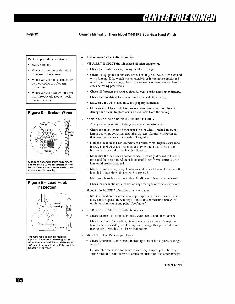
105
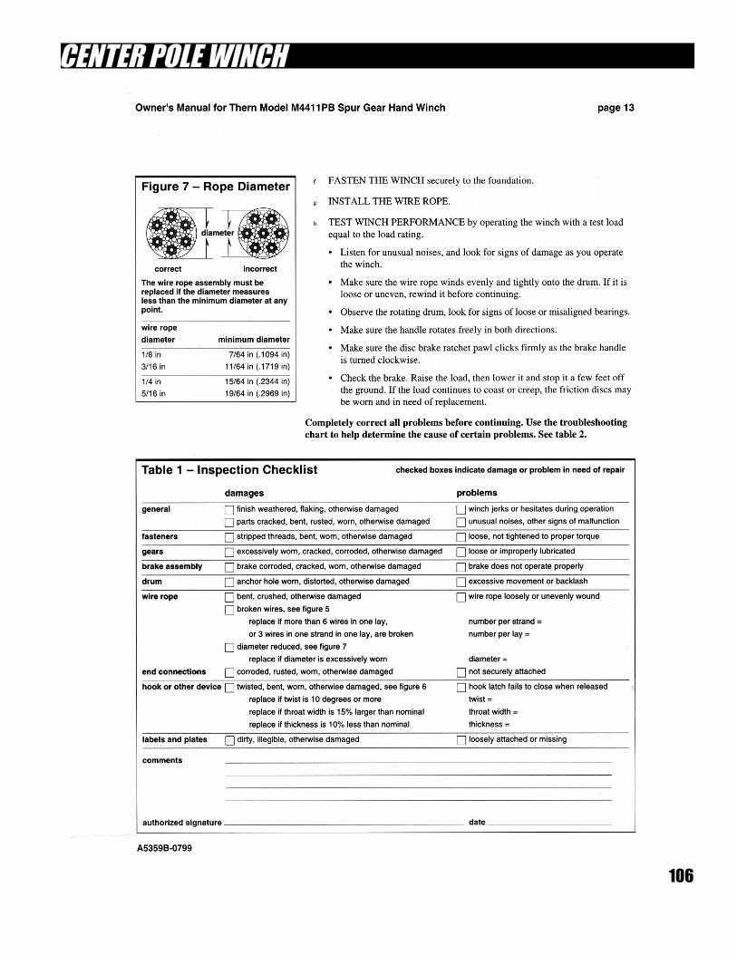
106
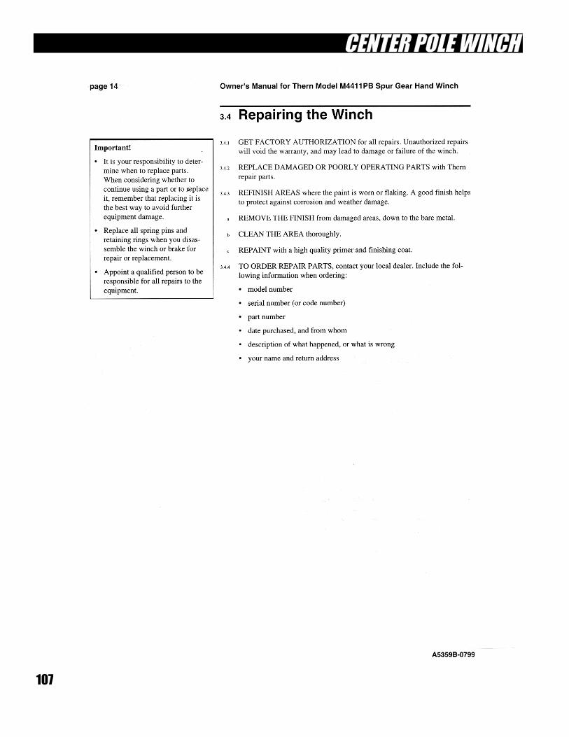
107
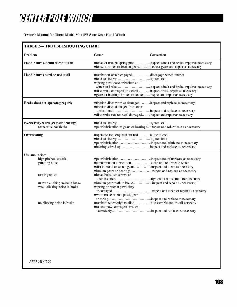
108
TABLE 2— TROUBLESHOOTING CHART
Problem Cause Correction
Handle turns, drum doesn’t turn ●loose or broken spring pins…………..inspect winch and brake, repair as necessary ●loose, stripped or broken gears……….inspect gears and repair as necessary
Handle turns hard or not at all ●ratchet on winch engaged…………….disengage winch ratchet ●load too heavy………………………..lighten load
●spring pins loose or broken on
winch or brake………………………..inspect winch and brake, repair as necessary
●disc brake damaged or locked………..inspect brake, repair as necessary
●gears or bearings broken or locked…..inspect and repair as necessary
Brake does not operate properly ●friction discs worn or damaged………inspect and replace as necessary ●friction discs damaged from over
lubrication…………………………….inspect and replace as necessary
●disc brake ratchet pawl damaged…….inspect and repair as necessary
Excessively worn gears or bearings ●load too heavy………………………..lighten load (excessive backlash) ●poor lubrication of gears or bearings…inspect and relubricate as necessary
Overheating ●operated too long without rest………..allow to cool ●load too heavy………………………...lighten load
●poor lubrication……………………….inspect and lubricate as necessary
●bearing seized up……………………..inspect and replace as necessary
Unusual noises high pitched squeak ●poor lubrication……………………….inspect and relubricate as necessary
grinding noise ●contaminated lubrication……………...clean and relubricate winch
●dirt in brake or winch gears…………...inspect and clean as necessary
●broken gears or bearings………………inspect and replace as necessary
rattling noise ●loose bolts, set screws or
other fasteners…………………………tighten all bolts and other fasteners
uneven clicking noise in brake ●broken gear tooth in brake……………..inspect and repair as necessary
weak clicking noise in brake ●spring or ratchet pawl dirty
or damaged…………………………….inspect and clean or repair as necessary
●worn brake ratchet pawl, gear,
or spring……………………………….inspect and replace as necessary
no clicking noise in brake ●ratchet incorrectly installed…………...disassemble and install correctly
●ratchet pawl damaged or worn
excessively…………………………….inspect and replace as necessary
A5359B-0799
Owner’s Manual for Thern Model M441PB Spur Gear Hand Winch
109
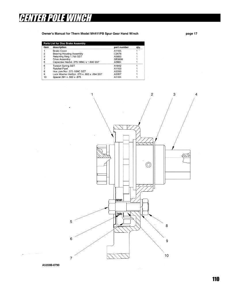
110
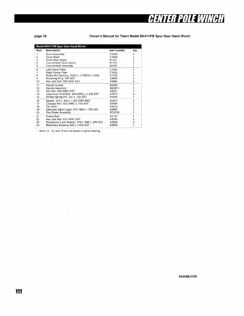
111
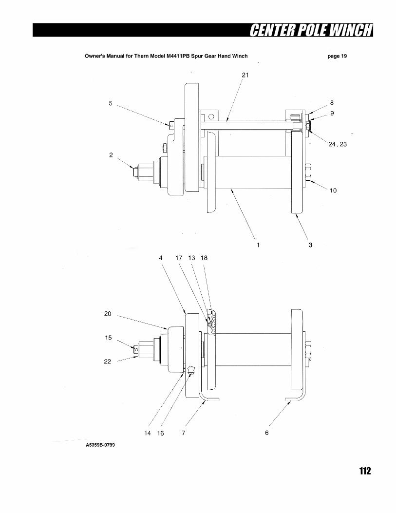
112

113