Embed Size (px)
Citation preview
Automated Fabrication of Ceramic Componentsfrom Tape-Cast Ceramic
Brian B. Mathewsonl, Wyatt S. Newman2
,
Arthur H. Heuer3, James D. Cawley4
ABSTRACTThis paper describes a machine and process for automated fabrication of functional 3-D
laminated engineering components, ceramics in the present example. A laser cuts successive layersof a part derived from a CAD model description out of unfired tape-cast ceramic sheetsvacuum-clamped to an x-y sled. A material-handling robot uses a selective-area gripper to extractonly the desired part outlines from the surrounding waste material, then stacks the slices to build thepart. This system design enables rapid manufacture of functional engineering components witharbitrarily complex internal and external geometries from virtually any material available in sheetform.
I. IntroductionThis paper describes the results ofour investigation ofa machine and process for automated
fabrication of laminated engineering components. The purpose of our system is to enable custommanufacturing of functional 3-D components with arbitrarily complex internal and externalgeometries.
We examined four key areas: testing a novel means of manipulating individual laminae ofarbitrary shapes; determining the achievable precision of robotically-assembled laminatedcomponents; determining the dimensional tolerance achievable by precompensating for partshrinkage that will occur during post-processing; and testing the mechanical strength of ceramicparts so produced. The first two are described here; structural performance and materials processingissues are presented in a separate publication within these proceedings [1].
System OverviewThe CAM-LEM approach is illustrated in Fig. 1. A part originates from a computer
description, which is analyzed to decompose the part into boundary contours of thin slices. Theseindividual slices are laser cut from "green" sheet stock per the computed contours. The resultingpart-slice regions are extracted from the sheet stock and stacked to assemble a physical 3-Drealization of the original CAD description. The assembly operation includes a "tacking," procedurethat fixes the position ofeach sheet relative to the pre-existing stack. After assembly, the layers are
lCAM-LEM Inc., Cleveland, Ohio.
2Associate Professor, Department of Electrical Engineering and Applied Physics, Case Western ReserveUniversity, Cleveland, Ohio.
3Kyocera Professor of Ceramics, Department of Materials Science and Engineering, Case Western ReserveUniversity, Cleveland, Ohio.
4Great Lakes Associate Professor of Ceramic Processing, Department of Materials Science andEngineering, Case Western Reserve University, Cleveland, Ohio.
253
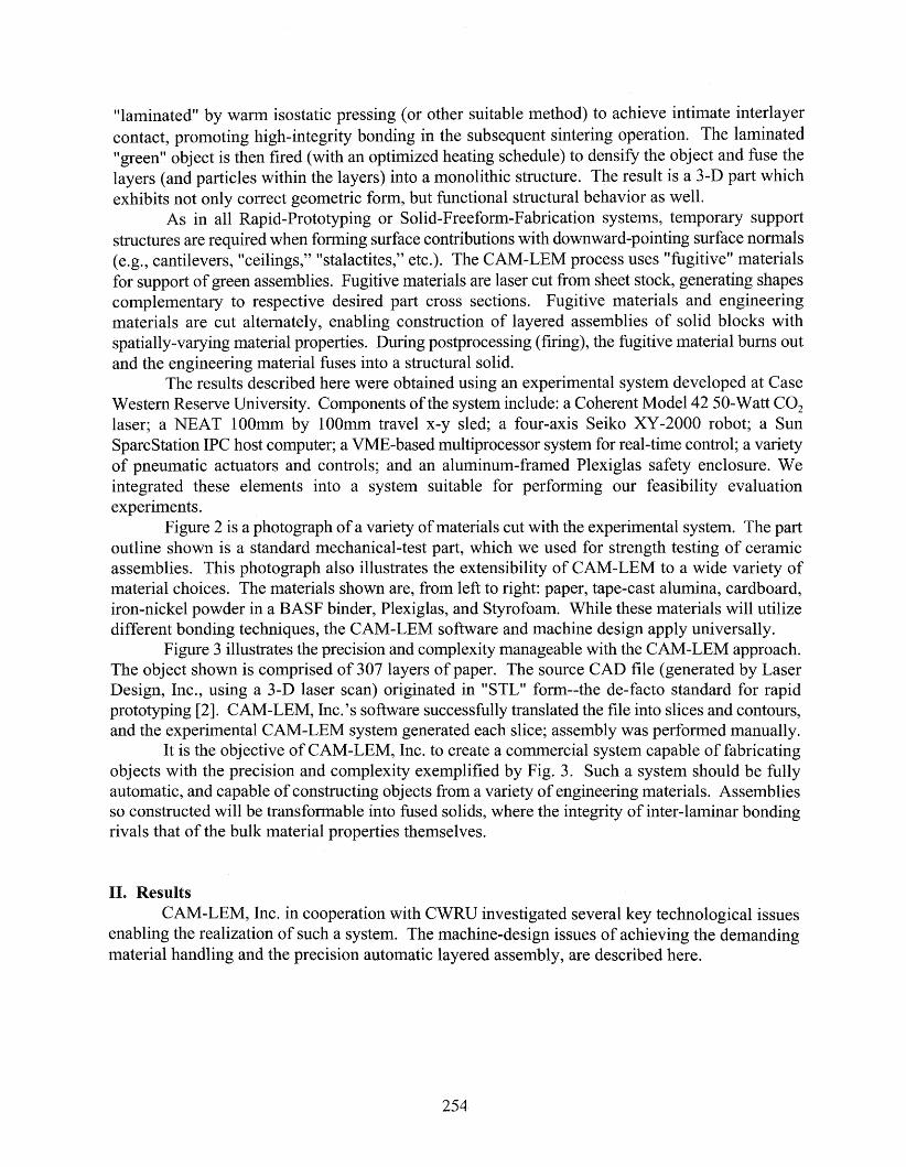
"laminated" by warm isostatic pressing (or other suitable method) to achieve intimate interlayercontact, promoting high-integrity bonding in the subsequent sintering operation. The laminated"green" object is then fired (with an optimized heating schedule) to densify the object and fuse thelayers (and particles within the layers) into a monolithic structure. The result is a 3-D part whichexhibits not only correct geometric form, but functional structural behavior as well.
As in all Rapid-Prototyping or Solid-Freeform-Fabrication systems, temporary supportstructures are required when forming surface contributions with downward-pointing surface normals(e.g., cantilevers, "ceilings," "stalactites," etc.). The CAM-LEM process uses "fugitive" materialsfor support ofgreen assemblies. Fugitive materials are laser cut from sheet stock, generating shapescomplementary to respective desired part cross sections. Fugitive materials and engineeringmaterials are cut alternately, enabling construction of layered assemblies of solid blocks withspatially-varying material properties. During postprocessing (firing), the fugitive material bums outand the engineering material fuses into a structural solid.
The results described here were obtained using an experimental system developed at CaseWestern Reserve University. Components ofthe system include: a Coherent Model 42 50-Watt CO2
laser; a NEAT 100mm by 100mm travel x-y sled; a four-axis Seiko XY-2000 robot; a SunSparcStation IPC host computer; a VME-based multiprocessor system for real-time control; a varietyof pneumatic actuators and controls; and an aluminum-framed Plexiglas safety enclosure. Weintegrated these elements into a system suitable for performing our feasibility evaluationexperiments.
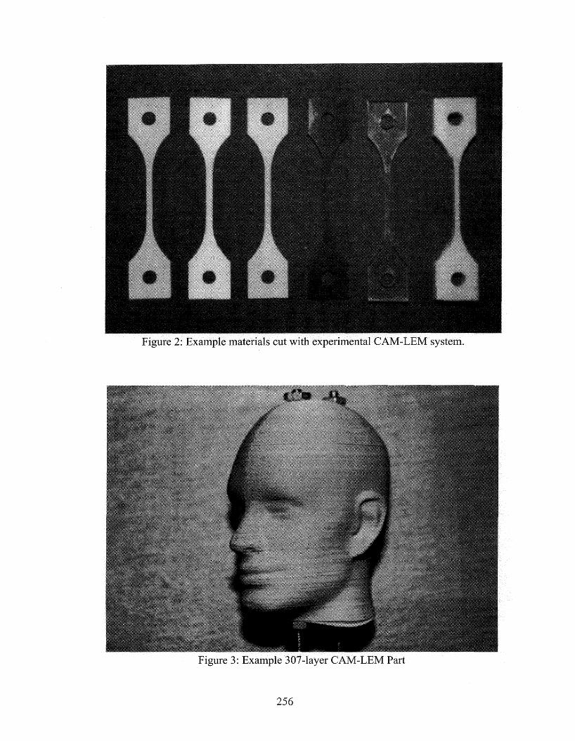
Figure 2 is a photograph of a variety ofmaterials cut with the experimental system. The partoutline shown is a standard mechanical-test part, which we used for strength testing of ceramicassemblies. This photograph also illustrates the extensibility of CAM-LEM to a wide variety ofmaterial choices. The materials shown are, from left to right: paper, tape-cast alumina, cardboard,iron-nickel powder in a BASF binder, Plexiglas, and Styrofoam. While these materials will utilizedifferent bonding techniques, the CAM-LEM software and machine design apply universally.
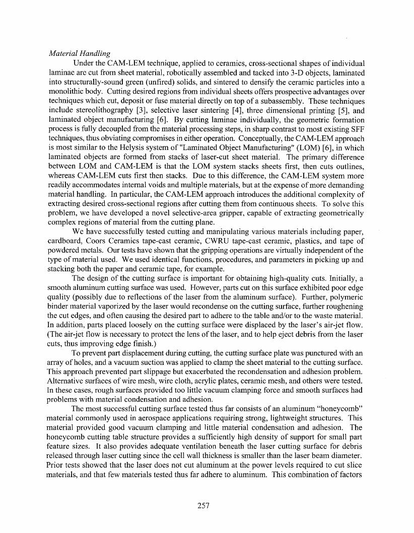
Figure 3 illustrates the precision and complexity manageable with the CAM-LEM approach.The object shown is comprised of 307 layers of paper. The source CAD file (generated by LaserDesign, Inc., using a 3-D laser scan) originated in "STL" form--the de-facto standard for rapidprototyping [2]. CAM-LEM, Inc. 's software successfully translated the file into slices and contours,and the experimental CAM-LEM system generated each slice; assembly was performed manually.
It is the objective of CAM-LEM, Inc. to create a commercial system capable of fabricatingobjects with the precision and complexity exemplified by Fig. 3. Such a system should be fullyautomatic, and capable ofconstructing objects from a variety of engineering materials. Assembliesso constructed will be transformable into fused solids, where the integrity of inter-laminar bondingrivals that of the bulk material properties themselves.
II. ResultsCAM-LEM, Inc. in cooperation with CWRU investigated several key technological issues
enabling the realization of such a system. The machine-design issues of achieving the demandingmaterial handling and the precision automatic layered assembly, are described here.
254
Computer Model
Contour Representation
Slice Cutting
Stacking
Lamination
Firing IFinished Component
Figure 1: The CAM-LEM Process
255
256
Material HandlingUnder the CAM-LEM technique, applied to ceramics, cross-sectional shapes of individual
laminae are cut from sheet material, robotically assembled and tacked into 3-D objects, laminatedinto structurally-sound green (unfired) solids, and sintered to densify the ceramic particles into amonolithic body. Cutting desired regions from individual sheets offers prospective advantages overtechniques which cut, deposit or fuse material directly on top of a subassembly. These techniquesinclude stereolithography [3], selective laser sintering [4], three dimensional printing [5], andlaminated object manufacturing [6]. By cutting laminae individually, the geometric formationprocess is fully decoupled from the material processing steps, in sharp contrast to most existing SFFtechniques, thus obviating compromises in either operation. Conceptually, the CAM-LEM approachis most similar to the Helysis system of "Laminated Object Manufacturing" (LaM) [6], in whichlaminated objects are formed from stacks of laser-cut sheet material. The primary differencebetween LaM and CAM-LEM is that the LaM system stacks sheets first, then cuts outlines,whereas CAM-LEM cuts first then stacks. Due to this difference, the CAM-LEM system morereadily accommodates internal voids and multiple materials, but at the expense ofmore demandingmaterial handling. In particular, the CAM-LEM approach introduces the additional complexity ofextracting desired cross-sectional regions after cutting them from continuous sheets. To solve thisproblem, we have developed a novel selective-area gripper, capable of extracting geometricallycomplex regions of material from the cutting plane.
We have successfully tested cutting and manipulating various materials including paper,cardboard, Coors Ceramics tape-cast ceramic, CWRU tape-cast ceramic, plastics, and tape ofpowdered metals. Our tests have shown that the gripping operations are virtually independent of thetype of material used. We used identical functions, procedures, and parameters in picking up andstacking both the paper and ceramic tape, for example.
The design of the cutting surface is important for obtaining high-quality cuts. Initially, asmooth aluminum cutting surface was used. However, parts cut on this surface exhibited poor edgequality (possibly due to reflections of the laser from the aluminum surface). Further, polymericbinder material vaporized by the laser would recondense on the cutting surface, further rougheningthe cut edges, and often causing the desired part to adhere to the table and/or to the waste material.In addition, parts placed loosely on the cutting surface were displaced by the laser's air-jet flow.(The air-jet flow is necessary to protect the lens of the laser, and to help eject debris from the lasercuts, thus improving edge finish.)
To prevent part displacement during cutting, the cutting surface plate was punctured with anarray ofholes, and a vacuum suction was applied to clamp the sheet material to the cutting surface.This approach prevented part slippage but exacerbated the recondensation and adhesion problem.Alternative surfaces of wire mesh, wire cloth, acrylic plates, ceramic mesh, and others were tested.In these cases, rough surfaces provided too little vacuum clamping force and smooth surfaces hadproblems with material condensation and adhesion.
The most successful cutting surface tested thus far consists of an aluminum "honeycomb"material commonly used in aerospace applications requiring strong, lightweight structures. Thismaterial provided good vacuum clamping and little material condensation and adhesion. Thehoneycomb cutting table structure provides a sufficiently high density of support for small partfeature sizes. It also provides adequate ventilation beneath the laser cutting surface for debrisreleased through laser cutting since the cell wall thickness is smaller than the laser beam diameter.Prior tests showed that the laser does not cut aluminum at the power levels required to cut slicematerials, and that few materials tested thus far adhere to aluminum. This combination of factors
257
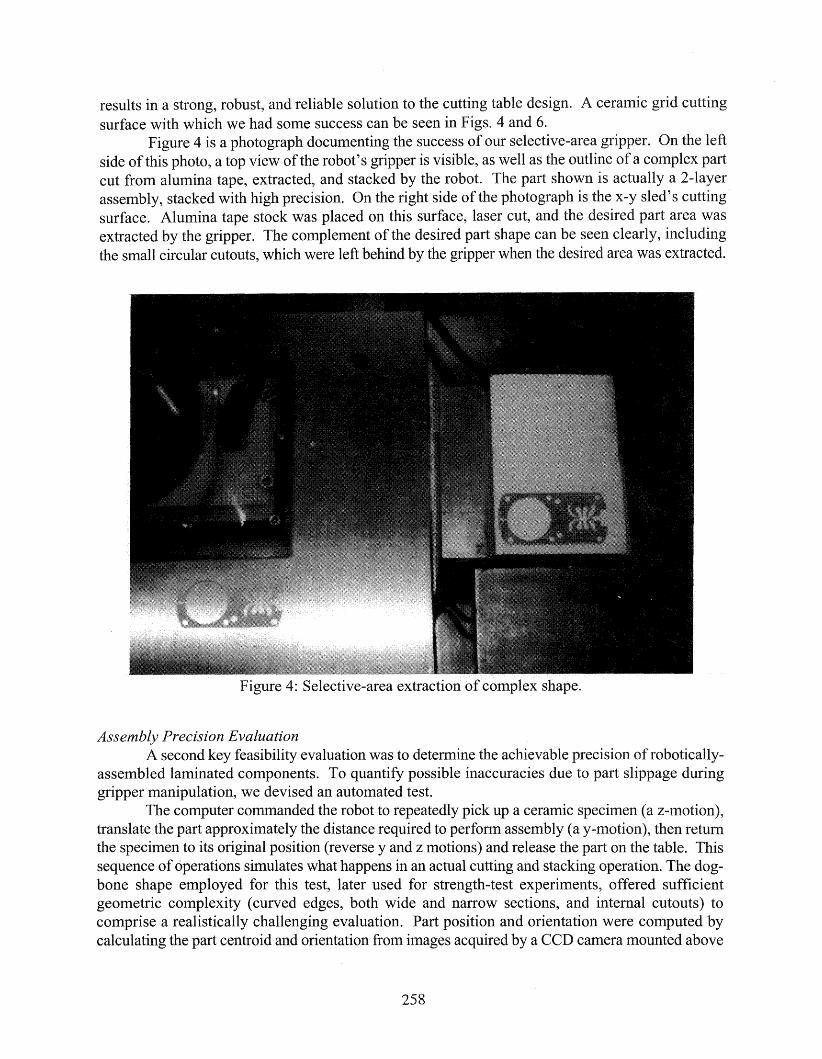
results in a strong, robust, and reliable solution to the cutting table design. A ceramic grid cuttingsurface with which we had some success can be seen in Figs. 4 and 6.
Figure 4 is a photograph documenting the success of our selective-area gripper. On the leftside of this photo, a top view of the robot's gripper is visible, as well as the outline of a complex partcut from alumina tape, extracted, and stacked by the robot. The part shown is actually a 2-layerassembly, stacked with high precision. On the right side of the photograph is the x-y sled's cuttingsurface. Alumina tape stock was placed on this surface, laser cut, and the desired part area wasextracted by the gripper. The complement of the desired part shape can be seen clearly, includingthe small circular cutouts, which were left behind by the gripper when the desired area was extracted.
Figure 4: Selective-area extraction of complex shape.
Assembly Precision EvaluationA second key feasibility evaluation was to determine the achievable precision ofrobotically
assembled laminated components. To quantify possible inaccuracies due to part slippage duringgripper manipulation, we devised an automated test.
The computer commanded the robot to repeatedly pick up a ceramic specimen (a z-motion),translate the part approximately the distance required to perform assembly (a y-motion), then returnthe specimen to its original position (reverse y and z motions) and release the part on the table. Thissequence of operations simulates what happens in an actual cutting and stacking operation. The dogbone shape employed for this test, later used for strength-test experiments, offered sufficientgeometric complexity (curved edges, both wide and narrow sections, and internal cutouts) tocomprise a realistically challenging evaluation. Part position and orientation were computed bycalculating the part centroid and orientation from images acquired by a CCD camera mounted above
258
IJVCU.LJ.'-HJ. of the part. After each manipulation cycle, the position of the part and its anglecamera were recorded to determine placement repeatability.
Placement Error, Y-Axis
IterationsPlacement Error, Rotation
o 5 10 15 20 25
252015Iterations
105
(3)c3 0.06
eO.04w
0.02
00
0.1.-----.-----.---------.-----.-------.
0.08
Part placement error during selective-area gripper handling
5 shows the results of 25 iterations of the test ofpart placement. plots show theposition of the part centroid location and part orientation between each iteration. The
standard deviation of the readings for y and the angle were microns and 0.021 degrees,respectively. 0.021 degree rotation about the center of the part results in a displacement of theouter of the test specimen by 14 microns.
these results we conclude that our selective area gripper is capable of moving parthigh repeatability. fact, handling errors are within the resolution limit of the Seiko
robot, so measurements only establish a conservative upper bound on the achievable
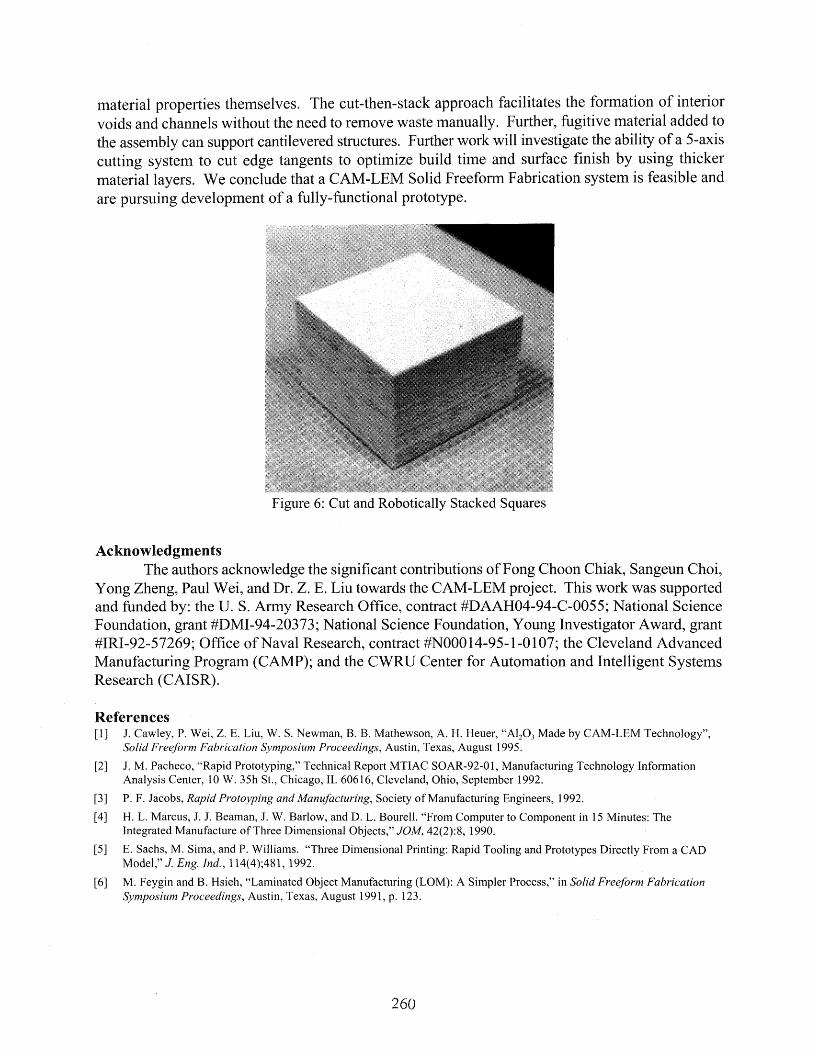
Further tests were performed on a robotically-stacked rectangular assembly, shown in Fig. 6.cross section, 24mm on a side, was laser cut froin Coors alumina tape, lifted by the
and onto the assembly. The assembly shown includes layers of 61 Omm-thickWhile the roughness of robotically-stacked assemblies has not yet been formally
~""'J.LJ.JlJ.""""", we subjectively conclude that the stacking accuracy exhibited our experimentsexcellent assembly precision.
have demonstrated the ability of the CAM-LEM system to create complex parts fromindustry-standard files. paper models exhibit precision cOinparable to other SFF
We have also shown how the CAM-LEM process can utilize other sheet materials, suchas create components with structural properties rivaling bulk
material properties themselves. The cut-then-stack approach facilitates the formation of interiorvoids and channels without the need to remove waste manually. Further, fugitive material added tothe assembly can support cantilevered structures. Further work will investigate the ability of a 5-axiscutting system to cut edge tangents to optimize build time and surface finish by using thickermaterial layers. We conclude that a CAM-LEM Solid Freeform Fabrication system is feasible andare pursuing development of a fully-functional prototype.
Figure 6: Cut and Robotically Stacked Squares
AcknowledgmentsThe authors acknowledge the significant contributions ofFong Choon Chiak, Sangeun Choi,
Yong Zheng, Paul Wei, and Dr. Z. E. Liu towards the CAM-LEM project. This work was supportedand funded by: the U. S. Army Research Office, contract #DAAH04-94-C-0055; National ScienceFoundation, grant #DMI-94-20373; National Science Foundation, Young Investigator Award, grant#IRI-92-57269; Office of Naval Research, contract #N00014-95-1-0107; the Cleveland AdvancedManufacturing Program (CAMP); and the CWRU Center for Automation and Intelligent SystemsResearch (CAISR).
References[1] 1. Cawley, P. Wei, Z. E. Liu, W. S. Newman, B. B. Mathewson, A. H. Heuer, "AI20} Made by CAM-LEM Technology",
Solid Freeform Fabrication Symposium Proceedings, Austin, Texas, August 1995.
[2] J. M. Pacheco, "Rapid Prototyping," Technical Report MTIAC SOAR-92-01, Manufacturing Technology InfonnationAnalysis Center, 10 W. 35h St., Chicago, IL 60616, Cleveland, Ohio, September 1992.
[3] P. F. Jacobs, Rapid Protoyping and Manufacturing, Society of Manufacturing Engineers, 1992.
[4] H. L. Marcus, J. J. Beaman, J. W. Barlow, and D. L. Bourell. "From Computer to Component in 15 Minutes: TheIntegrated Manufacture of Three Dimensional Objects," JOM, 42(2):8, 1990.
[5] E. Sachs, M. Sima, and P. Williams. "Three Dimensional Printing: Rapid Tooling and Prototypes Directly From a CADModel," J. Eng. Ind., 114(4);481, 1992.
[6] M. Feygin and B. Hsieh, "Laminated Object Manufacturing (LaM): A Simpler Process," in Solid Freeform FabricationSymposium Proceedings, Austin, Texas, August 1991, p. 123.
260


![EFFECTS OF MANUFACTURING DEFECTS ON THE … Turoski.pdfAutomated tape and tow-laying in composite fabrication has increased significantly in recent years [Grant, (2000)]. Automated](https://img.pdfslide.net/doc/110x75/5e824c07b74f34736a2746ed/effects-of-manufacturing-defects-on-the-turoskipdf-automated-tape-and-tow-laying.jpg)