Embed Size (px)
Citation preview
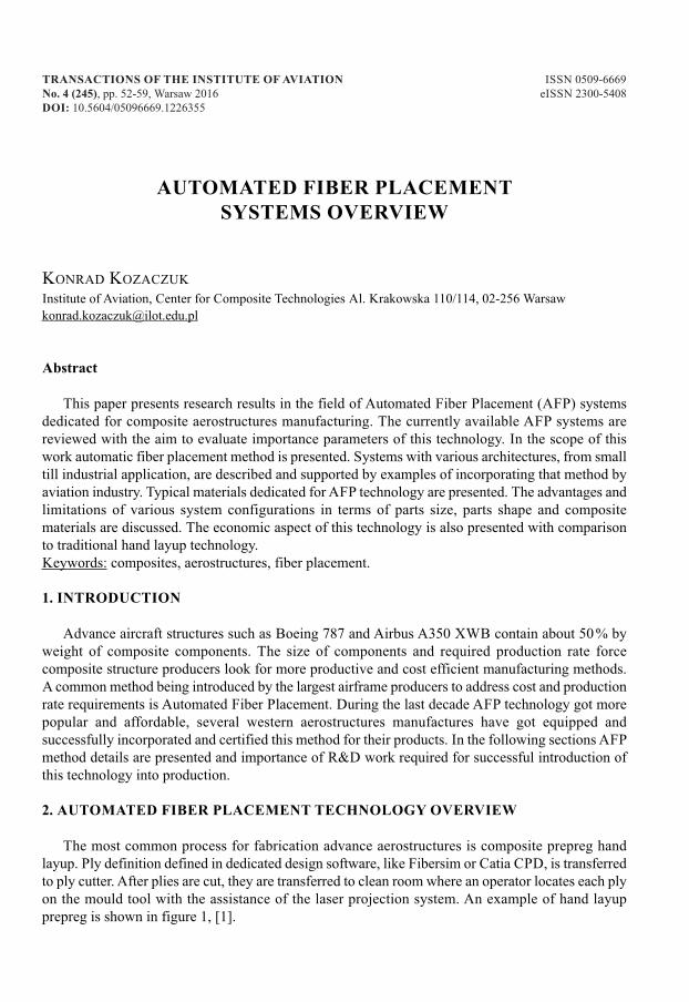
transactions of the institute of aviation ISSN 0509-6669no. 4 (245), pp. 52-59, Warsaw 2016 eISSN 2300-5408Doi: 10.5604/05096669.1226355
autoMateD fiBer PLaceMent sYsteMs overvieW
KoNrad KozaczuKInstitute of aviation, center for composite Technologies al. Krakowska 110/114, 02-256 [email protected]
abstract
This paper presents research results in the field of automated Fiber Placement (aFP) systemsdedicated for composite aerostructures manufacturing. The currently available aFP systems arereviewed with the aim to evaluate importance parameters of this technology. In the scope of thiswork automatic fiber placement method is presented. Systems with various architectures, from smalltill industrial application, are described and supported by examples of incorporating that method byaviation industry. Typical materials dedicated for aFP technology are presented. The advantages andlimitations of various system configurations in terms of parts size, parts shape and compositematerials are discussed. The economic aspect of this technology is also presented with comparisonto traditional hand layup technology.Keywords: composites, aerostructures, fiber placement.
1. introDuction
advance aircraft structures such as Boeing 787 and airbus a350 XWB contain about 50 % byweight of composite components. The size of components and required production rate forcecomposite structure producers look for more productive and cost efficient manufacturing methods.a common method being introduced by the largest airframe producers to address cost and productionrate requirements is automated Fiber Placement. during the last decade aFP technology got morepopular and affordable, several western aerostructures manufactures have got equipped andsuccessfully incorporated and certified this method for their products. In the following sections aFPmethod details are presented and importance of r&d work required for successful introduction ofthis technology into production.
2. autoMateD fiBer PLaceMent technoLoGY overvieW
The most common process for fabrication advance aerostructures is composite prepreg handlayup. Ply definition defined in dedicated design software, like Fibersim or catia cPd, is transferredto ply cutter. after plies are cut, they are transferred to clean room where an operator locates each plyon the mould tool with the assistance of the laser projection system. an example of hand layupprepreg is shown in figure 1, [1].
53auTomaTEd FIBEr PLacEmENT SySTEmS ovErvIEW
Fig. 1. Basic composite part fabrication with hand layup method [SL-Laser GmbH, 2015]
The advantages of hand layup lie in the fact that this method does not require expensive equipmentand an experienced operator can fabricate parts with a complex shape. The main disadvantages arereferred to the quality of parts which is dependent on experience of the operator and also the fact thatthis method is relatively slow. considering this fact, western airframe producers started to look fora more efficient method. The solution for this need is automated Fiber Placement technology [2].
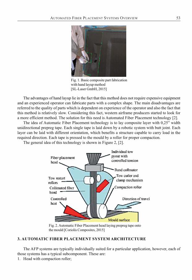
The idea of automatic Fiber Placement technology is to lay composite layer with 0,25” widthunidirectional prepreg tape. Each single tape is laid down by a robotic system with butt joint. Eachlayer can be laid with different orientation, which benefits a structure capable to carry load in therequired direction. Each tape is pressed to the mould by a roller for proper compaction.
The general idea of this technology is shown in Figure 2, [2].
Fig. 2. automatic Fiber Placement head laying prepreg tape onto the mould [coriolis composites, 2015]
3. autoMatic fiBer PLaceMent sYsteM architecture
The aFP systems are typically individually suited for a particular application, however, each ofthose systems has a typical subcomponent. These are:1. Head with compaction roller;
54 KoNrad KozaczuK
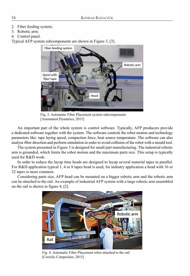
2. Fiber feeding system;3. robotic arm;4. control panel.Typical aFP system subcomponents are shown in Figure 3, [3].
Fig. 3. automatic Fiber Placement system subcomponents [automated dynamics, 2015]
an important part of the whole system is control software. Typically, aFP producers provide a dedicated software together with the system. The software controls the robot motion and technologyparameters like: tape laying speed, compaction force, heat source temperature. The software can alsoanalyse fiber direction and perform simulation in order to avoid collision of the robot with a mould tool.
The system presented in Figure 3 is designed for small part manufacturing. The industrial roboticarm is grounded, which limits the robot motion and the maximum parts size. This setup is typicallyused for r&d work.
In order to reduce the layup time heads are designed to layup several material tapes in parallel.For r&d application typical 1, 4 or 8 tapes head is used, for industry application a head with 16 or32 tapes is more common.
considering parts size, aFP head can be mounted on a bigger robotic arm and the robotic armcan be attached to the rail. an example of industrial aFP system with a large robotic arm assembledon the rail is shown in figure 4, [2].
Fig. 4. automatic Fiber Placement robot attached to the rail [coriolis composites, 2015]
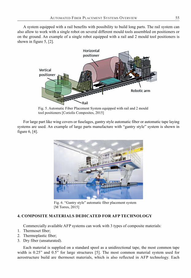
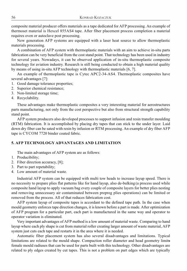
a system equipped with a rail benefits with possibility to build long parts. The rail system canalso allow to work with a single robot on several different mould tools assembled on positioners oron the ground. an example of a single robot equipped with a rail and 2 mould tool positioners isshown in figure 5, [2].
Fig. 5. automatic Fiber Placement System equipped with rail and 2 mouldtool positioners [coriolis composites, 2015]
For large part like wing covers or fuselages, gantry style automatic fiber or automatic tape layingsystems are used. an example of large parts manufacture with “gantry style” system is shown infigure 6, [4].
Fig. 6. “Gantry style” automatic fiber placement system [m Torres, 2015]
4. coMPosite MateriaLs DeDicateD for afP technoLoGY
commercially available aFP systems can work with 3 types of composite materials:1. Thermoset fiber;2. Thermoplastic fiber;3. dry fiber (unsaturated).
Each material is supplied on a standard spool as a unidirectional tape, the most common tapewidth is 0.25” and 0.5” for large structures [5]. The most common material system used foraerostructure build are thermoset materials, which is also reflected in aFP technology. Each
55auTomaTEd FIBEr PLacEmENT SySTEmS ovErvIEW
composite material producer offers materials as a tape dedicated for aFP processing. an example ofthermoset material is Hexcel 855aS4 tape. after fiber placement process completion a materialrequires oven or autoclave post processing.
New generation aFP systems are equipped with a laser heat source to allow thermoplasticmaterials processing.
a combination of aFP system with thermoplastic materials with an aim to achieve in-situ partsfabrication can be very beneficial from the cost stand point. That technology has been used in industryfor several years. Nowadays, it can be observed application of in-situ thermoplastic compositetechnology for aviation industry. research is still being conducted to obtain a high material qualityby means of using in-situ aFP technology with thermoplastic materials [6, 7].
an example of thermoplastic tape is cytec aPc2-34-aS4. Thermoplastic composites haveseveral advantages [7]:1. Good damage tolerance properties;2. Superior chemical resistance;3. Non-limited storage time;4. recyclability.
These advantages make thermoplastic composites a very interesting material for aerostructuresparts manufacturing, not only from the cost perspective but also from structural strength capabilitystand point.
aFP system producers also developed processes to support infusion and resin transfer moulding(rTm) fabrication. It is accomplished by placing dry tapes that can stick to the under layer. Laiddown dry fiber can be sated with resin by infusion or rTm processing. an example of dry fiber aFPtape is cycom 7720 binder coated fabric.
5. afP technoLoGY aDvantaGes anD LiMitation
The main advantages of aFP system are as follows:1. Producibility;2. Fiber direction accuracy, [8];3. Part to part repetability;4. Low amount of material waste.
Industrial aFP system can be equipped with multi tow heads to increase layup speed. There isno necessity to prepare plies flat patterns like for hand layup, also de-bulking (a process used whilecomposite hand layup to apply vacuum bag every couple of composite layers for better plies nestingand removing unnecessary air contaminated between prepreg plies operations) can be limited orremoved from the process. all of that reduces fabrication cost.
aFP system layup of composite tapes is accordant to the defined tape path. In the case whenmould geometry enforces tape direction changes, it is known before a part is made. after optimizationof aFP program for a particular part, each part is manufactured in the same way and operator tooperator variation is eliminated.
very important advantages of aFP method is a low amount of material waste. comparing to handlayup where each ply shape is cut from material roller creating larger amount of waste material, aFPsystem just cuts each tape and restarts it in the area where it is needed.
automatic fiber placement system has also several disadvantages and limitations. Typicallimitations are related to the mould shape. compaction roller diameter and head geometry limitsfemale mould radiuses that can be used for parts built with this technology. other disadvantages arerelated to ply edges created by cut tapes. This is not a problem on part edges which are typically
56 KoNrad KozaczuK
57auTomaTEd FIBEr PLacEmENT SySTEmS ovErvIEW
trimmed, however, in local composite build ups sawblade shape ply contour, (figure 7) is a phenomenon that a designer needs to accept [2].
Fig. 7. Ply edge with characteristic sawblade contour obtained by aFP process [coriolis composites, 2015]
6. econoMic asPect of afP technoLoGY
The speed of hand layup is depended on several factors, however, a good average is 1 hour ofwork to hand layup 1m2 of prepreg material. Having a fairing with the area of 2 m2 meters and onaverage 10 plies, it takes 20 hours to hand layup a single part. That time is driven by ply cut operationperformed before hand layup and de-bulking process done while layup operation.
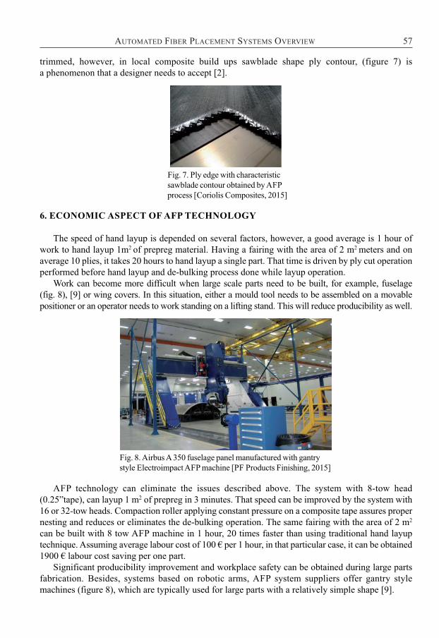
Work can become more difficult when large scale parts need to be built, for example, fuselage (fig. 8), [9] or wing covers. In this situation, either a mould tool needs to be assembled on a movablepositioner or an operator needs to work standing on a lifting stand. This will reduce producibility as well.
Fig. 8. airbus a 350 fuselage panel manufactured with gantry style Electroimpact aFP machine [PF Products Finishing, 2015]
aFP technology can eliminate the issues described above. The system with 8-tow head(0.25”tape), can layup 1 m2 of prepreg in 3 minutes. That speed can be improved by the system with16 or 32-tow heads. compaction roller applying constant pressure on a composite tape assures propernesting and reduces or eliminates the de-bulking operation. The same fairing with the area of 2 m2
can be built with 8 tow aFP machine in 1 hour, 20 times faster than using traditional hand layuptechnique. assuming average labour cost of 100 € per 1 hour, in that particular case, it can be obtained1900 € labour cost saving per one part.
Significant producibility improvement and workplace safety can be obtained during large partsfabrication. Besides, systems based on robotic arms, aFP system suppliers offer gantry stylemachines (figure 8), which are typically used for large parts with a relatively simple shape [9].
considering the latest Boeing and airbus airplanes with a significant usage of composite parts,the necessity to increase composite parts manufacturing capability is obvious. Both largest airframeproducers advertise introduction of aFP methods for production of their structures. cost reductionof manufacturing processes and the need to increase production rate are key reasons for this choice,[10].
Thermoplastic tapes dedicated for aFP systems introduction is another great opportunity for partcost reduction. It is expected that the usage of aFP thermoplastic technology in primary structureswill grow in the coming years [6].
7. concLusions
on the basis of the conducted research the following conclusions have been drawn:1. The newest Boeing and airbus Large aircraft designs contain up to 50% of composite parts by
weigh. airframers have been looking for effective technology for composite structure fabricationand succesfully introduced aFP technology into production.
2. The presented examples of accommodating aFP method into current production by airbus andBoeing proves that aFP technology achieved high technology readiness level. It is expected thatsmall and mid size airframe manufacturers will work on introducing this technology in theirproduction.
3. World class airframers with cooperation with aFP system producers are continuously conductingr&d work in this field. It is expected that aviation industry needs in the field of aFP technologyr&d services will grow [11].
4. considering aFP technology limitation related to parts shape, it is importand to design partsespecially for this technology. That creates the need for cooperation between design office andaFP r&d center from the conceptual phase of a project.
5. aFP technology significantly reduces time of a part manufacturing, 8 tow head machine canreduce 20 times layup time in comparison with hand layup.
6. aFP technology ensures parts repeatability, especially in the field of fiber direction and fibertrim.
7. although aFP technology with thermoset materials was successfully introduced into production,the usage of aFP technology with thermoplastic composites is still on the preliminary phase.aFP system equipped with a laser heat source allows to conduct r&d work with thermoplastictape and in-situ fabrication. combination of aFP method cost advantages and thermoplasticcomposite material properties advantages can be very beneficial.
acknowledgements
This work was carried out within the framework of the statutory project: Automated FiberPlacement technology introduction.
BiBLioGraPhY
[1] SL-Laser, 2015, “composites”, from http://www.sl-laser.com/en/welcome/9-kategorieanwendung/127-composites-en.html.
[2] coriolis, 2015, “coriolis composites”, from http://www.coriolis-composites.com/company/about.html.
[3] automated dynamics, 2015, “automated dynamics Performance in composites”, fromhttp://www.automateddynamics.com/.
58 KoNrad KozaczuK
59auTomaTEd FIBEr PLacEmENT SySTEmS ovErvIEW
[4] mtorres, 2015, “aeronautics”, from http://www.mtorres.es/en/aeronautica.[5] Flynn, r., Nielson J., and rudberg, T., 2010, “Production Implementation of multiple
machine, High Speed Fiber Placement for Large Structures”.[6] mondo J., Wijskamp S. and Lenferink r., 2012, “overview of Thermoplastic composite
aTL and aFP Technologies”.[7] august, z., ostrander, G., michasiow, J. and Hauber, d., 2013, “recent developments in
automated fiber placement of thermoplastic composites”.[8] Haintze K., 2009, computer methods in optimalization of Fiber composites Structure,
Transactions of the Institute of aviation, 200, pp. 60-71.[9] PF Products Finishing, 2015, “a350 XWB update”, from
http://www.pfonline.com/articles/panelized-option-attested-early-on.[10] Iwaniuk a., Wiśniowski W., Żółtak J., “multi-disciplinary optimization approach for a light
turboprop aircraft-engine integration and improvement”, aircraft Engineering and aerospaceTechnology, vol. 88, Issue 2, pp. 348-355.
[11] Piwek K., Wiśniowski W., 2016, „Small air transport aircraft entry requirements evoked byFlightPath 2050”, aircraft Engineering and aerospace Technology, vol. 88, Issue 2, pp. 341-347.
PrZeGLĄD sYsteMÓW ZroBotYZoWaneGouKŁaDania taŚM KoMPoZYtoWYch
streszczenie
W artykule przedstawiono wyniki analizy w zakresie zrobotyzowanych Systemów układaniaTaśm Kompozytowych dedykowanych do produkcji kompozytowych struktur lotniczych.zaprezentowano podstawy technologii układania taśm kompozytowych, przeanalizowano dostępneobecnie systemy w zakresie istotnych parametrów technologicznych. Przedstawiono architekturęwspółczesnych systemów układania taśm, rozpoczynając od niewielkich urządzeń przystosowanychdo prac badawczo rozwojowych aż do dużych urządzeń przemysłowych. opisano i popartoprzykładami wprowadzenie tej metody do przemysłu lotniczego. zaprezentowano typowe materiałyprzeznaczone dla technologii zrobotyzowanego układania Taśm Kompozytowych. Przedstawionozalety i ograniczenia różnych konfiguracjach systemów pod względem wielkości wytwarzanychczęści, ich kształtu oraz używanych materiałów kompozytowych. omówiono ekonomiczny aspektużycia tej technologii w odniesieniu do tradycyjnej technologii ręcznego układania preimpregnatówkompozytowych.Słowa kluczowe: kompozyty, struktury lotnicze, taśmy kompozytowe.