Embed Size (px)
Citation preview
American Institute of Aeronautics and Astronautics
1
Automated Generation of Finite-Element Meshes for
Aircraft Conceptual Design
Wu Li1 and Jay Robinson2
NASA Langley Research Center, Hampton, Virginia 23681, USA
This paper presents a novel approach for automated generation of fully connected finite-
element meshes for all internal structural components and skins of a given wing-body
geometry model, controlled by a few conceptual-level structural layout parameters. Internal
structural components include spars, ribs, frames, and bulkheads. Structural layout
parameters include spar/rib locations in wing chordwise/spanwise direction and
frame/bulkhead locations in longitudinal direction. A simple shell thickness optimization
problem with two load conditions is used to verify versatility and robustness of the automated
meshing process. The automation process is implemented in ModelCenter starting from an
OpenVSP geometry and ending with a NASTRAN 200 solution. One subsonic configuration
and one supersonic configuration are used for numerical verification. Two different structural
layouts are constructed for each configuration and five finite-element meshes of different sizes
are generated for each layout. The paper includes various comparisons of solutions of 20
thickness optimization problems, as well as discussions on how the optimal solutions are
affected by the stress constraint bound and the initial guess of design variables.
Nomenclature
x, y, z = coordinates of a point in a three-dimensional space
FEA = finite-element analysis
FEM = finite-element model
LE = leading edge of wing
TE = trailing edge of wing
I. Introduction
ULL aircraft finite-element analysis (FEA) is labor-intensive with a relatively long turn-around time (months or
years). Available automation approaches for FEA during aircraft conceptual design are primarily developed for
individual aircraft components. Internal structural components (such as spars and ribs) are generated for one aircraft
component (such as a wing) using a parametric scheme, and fully connected finite-element meshes can be
automatically generated for the aircraft component (see, e.g., Refs. 1 and 2). Here, a fully connected finite-element
mesh means that every two connected elements share the same nodes at the common edge. In contrast, there are other
methods that can virtually connect two disconnected elements with constraints. The virtual connectivity can be
established either manually or via NASTRAN3 glue operation.4 There are also efforts to automatically generate a fully
connected finite-element mesh for multiple aircraft components such as fuselage and wing. RapidFEM5 represents the
state-of-the-art in automated generation of fully connected finite-element meshes for multiple aircraft components. It
uses a 2D sketch to define the internal structural components, generates a finite-element mesh for each aircraft
component, and applies a merge algorithm to combine component meshes into one fully connected finite-element
mesh; however, any automation approach based on merging or gluing component meshes faces two key technical
challenges: (1) automatically connecting internal structural elements to form proper load paths and (2) avoiding
triangles of poor aspect ratios when connecting different aircraft components.
This paper presents a novel approach for automated generation of a fully connected finite-element mesh for
fuselage and aerodynamic surfaces of an aircraft configuration. In theory, this approach can be applied to any
component-based geometry model in OpenVSP6 Hermite format,7 but the current implementation is only completed
1 Senior Research Engineer, Aeronautics Systems Analysis Branch, Mail Stop 442 2 Aerospace Engineer, Aeronautics Systems Analysis Branch, Mail Stop 442
F
https://ntrs.nasa.gov/search.jsp?R=20160010023 2018-06-27T21:29:45+00:00Z

American Institute of Aeronautics and Astronautics
2
for fuselage and wing to demonstrate the feasibility of such an automation process. The key idea is to generate a
geometry model for internal structural components and skins such that any two connected surfaces share a common
boundary curve. Such a geometry model will be called “FEM-ready” geometry because it enables automated
generation of a fully connected finite-element mesh.
The envisioned process for automation of FEA for aircraft conceptual design can be summarized as follows:
1. Specify conceptual-level layout parameters for internal structural components.
2. Generate a fully connected surface geometry model (FEM-ready geometry) for internal structural
components and skins using piecewise linear approximations of the original geometry model.
3. Identify watertight compartments using the surfaces for internal structural components and skins.
4. Apply the advancing front method8 in Geompack++9 to generate a fully connected quadrilateral mesh or
HYBRID mesher in PATRAN10 to generate a fully connected finite-element mesh for the collection of
watertight compartments.
5. Assign all structural elements to predefined groups.
6. Select material properties for the predefined groups using a knowledge-based material database.
7. Create aero panels for fuselage and aerodynamic surfaces using piecewise linear approximations.
8. Couple aero panels and structural elements using splines and 2D projection mappings.
9. Add concentrated masses to model other components of the airplane configuration such as landing gear,
engines, and fuel tanks.
10. Define load conditions using a knowledge-based load database.
11. Generate NASTRAN decks of the inputs for NASTRAN aeroelastic analysis or optimization.
A watertight compartment is very similar to a watertight outer mold line for computational fluid dynamics surface
meshing. The only difference is that a watertight compartment might contain internal surfaces (see subsection II.A).
The aero-structure coupling is out of the scope of this paper. Instead, steps 7-10 are replaced with two simple load
cases of applying constant pressure on the wing surface upward and downward, respectively.
The resulting automated FEA process is implemented in ModelCenter11 (see Fig. 1). The automation process (i)
starts with an OpenVSP geometry model (LoadGeoFile), (ii) uses a set of conceptual-level layout parameters to
generate the FEM-ready geometry with internal structural components (conceptFEM), (iii) generates a fully connected
finite-element mesh (conceptFEM), (iv) specifies upward and downward constant wing pressure loads, as well as the
bound for von Mises stress on all elements (SizingInputs), (v) uses the thickness of each partition surface in the FEM-
ready geometry as a design variable, specifies the bounds for design variables, and chooses an initial guess for design
variables (SizingInputs), (vi) defines material properties for 16 different predefined groups of elements (SizingInputs
and materialsDB), (vii) generates the corresponding NASTRAN bulk data for thickness optimization (conceptSizing),
and (viii) runs NASTRAN design optimization (conceptSizing).
Figure 1. ModelCenter process for automated FEA.
Section II introduces the numerical methods used in the automated FEA process, including the construction of
FEM-ready geometry, automated finite-element meshing, and formulation and solution of the thickness optimization
problem. Detailed discussions on user input requirements to run the process are given in Section III. One supersonic
configuration and one subsonic configuration are used for numerical verification of the automation process. Two
different structural layouts are constructed for each configuration and five finite-element meshes of different sizes are
generated for each layout. Section IV includes various comparisons of solutions of the 20 thickness optimization
problems, as well as discussions on how the optimal solutions are affected by stress constraint bound and initial guess
of design variables. Concluding remarks are given in Section V.
II. Automated FEA Process
The analysis component conceptFEM in Fig. 1 constructs FEM-ready geometry and generates a finite-element
mesh using a set of conceptual-level structural layout parameters. Material assignments are performed by materialsDB
in Fig. 1. All the required parameters for setting up a thickness optimization problem under two constant pressure load
conditions on the wing are fed to the design component conceptSizing, which calculates optimal thickness distribution
American Institute of Aeronautics and Astronautics
3
and optimal structural weight. However, conceptSizing could also use a given set of thickness parameters without
thickness optimization and get a linear static (NASTRAN 101) solution. Tecplot12 is used to plot FEM-ready geometry
and finite-element mesh. PATRAN is used to plot NASTRAN solutions.
The numerical methods behind the automated FEA process will be described in the following three subsections.
Subsection A discusses the construction of FEM-ready geometry. Subsection B introduces two meshing tools that can
robustly generate fully connected finite-element meshes for a FEM-ready geometry and discusses their pros and cons.
The last subsection describes the bookkeeping process of converting all generated data for thickness optimization into
bulk data format for NASTRAN design optimization runs.
A. Construction of FEM-Ready Geometry
The existing automation processes4,5 for FEA of multiple aircraft components are based on merging/gluing finite-
element meshes of aircraft components after construction of finite-element meshes for every component
independently. Here is a novel approach of separating construction of internal structural components and generation
of finite-element meshes. The key idea is to construct a fully connected geometry model that contains all internal
components. Such a geometry model is referred to as FEM-ready geometry. A FEM-ready geometry model not only
contains all internal structural components, but also satisfies the condition that any two connected surfaces share the
same boundary curve.
The main motivation for introducing FEM-ready geometry is that several meshing tools can be used to generate a
fully connected finite-element mesh of a FEM-ready geometry without any further manual preprocessing of the
geometry (see the next subsection). The separation of internal structural component construction and meshing avoids
the merge of disconnected structural meshes. Instead, the construction of FEM-ready geometry only needs to deal
with the connectivity of various structural components and generates the desired layout topology, while leaving the
meshing problem to professionally/commercially developed meshing tools. This strategy will ensure the use of the
state-of-the-art meshing technology in the automated FEA process.
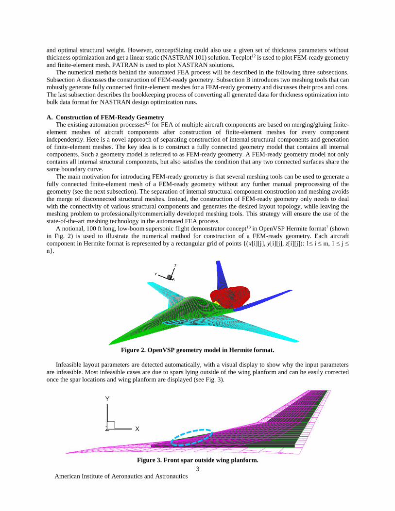
A notional, 100 ft long, low-boom supersonic flight demonstrator concept13 in OpenVSP Hermite format7 (shown
in Fig. 2) is used to illustrate the numerical method for construction of a FEM-ready geometry. Each aircraft
component in Hermite format is represented by a rectangular grid of points {(x[i][j], y[i][j], z[i][j]): 1≤ i ≤ m, 1 ≤ j ≤
n}.
Figure 2. OpenVSP geometry model in Hermite format.
Infeasible layout parameters are detected automatically, with a visual display to show why the input parameters
are infeasible. Most infeasible cases are due to spars lying outside of the wing planform and can be easily corrected
once the spar locations and wing planform are displayed (see Fig. 3).
Figure 3. Front spar outside wing planform.

American Institute of Aeronautics and Astronautics
4
If the layout parameters are feasible, all internal structural components are defined by using piecewise linear
approximations of the original geometry model. For example, a typical spar surface outside the fuselage is bounded
above by the upper wing skin surfaces, bounded below by the lower wing skin surfaces, and bounded on two sides by
rib surfaces. After construction of fully connected internal structural components, new surfaces for the outer mold line
of the fuselage and wing are generated (using linear approximations) so that all surfaces are fully connected for
meshing. That is, if two surfaces are connected, then they share a common boundary curve. Figure 4 shows fully
connected surfaces for internal structural components and skins (with some skins hidden to expose the internal
structural components).
Figure 4. Fully connected surfaces (FEM-ready geometry) for internal structural components and skins.
The [discrete] geometry model in Fig. 4 can be considered as a fully connected finite-element mesh with triangles
and quadrilaterals. But, in general, it cannot be used for FEA because poor aspect ratios of elements and their irregular
sizes might lead to faulty FEA results.
One could also view the FEM-ready geometry as a [continuous] geometry model defined by bilinear B-splines.14
Then various finite-element meshes for the underlying bilinear B-spline geometry can be easily generated using
PATRAN’s meshers without any further preprocessing of the geometry model. See the next subsection for details.
Another option to automatically generate a fully connected quadrilateral mesh for the FEM-ready geometry is to
use the advancing front method in the meshing software Geompack++. For quadrilateral surface meshing,
Geompack++ requires a decomposition of the input geometry into watertight compartments with proper orientations
of surface normal. A pattern recognition algorithm is developed to rearrange all surfaces into watertight compartments.
A watertight compartment is very similar to a watertight outer mold line. The only difference is that a watertight
compartment might contain internal surfaces. Figure 5 shows the most complicated watertight compartment for the
notional low-boom demonstrator concept with four spars and cutouts above them inside the fuselage. Four fuselage
skin surfaces are hidden in Fig. 5 to expose the internal surfaces, which include ring surfaces (for a frame) at the
trailing edge of the fuselage/wing intersection and surfaces for four spars inside the fuselage.
Figure 5. A watertight compartment [with some fuselage skin surfaces hidden].

American Institute of Aeronautics and Astronautics
5
B. Automated Finite-Element Meshing
The current automation process uses the HYBRID mesher in PATRAN and the advancing front method in
Geompack++ to generate fully connected finite-element meshes for any FEM-ready geometry. HYBRID can generate
finite-element meshes of various sizes by using a global length control parameter, but the generated mesh usually
contains a few triangles. The advancing front method in Geompack++ can always generate a fully connected
quadrilateral mesh, but it is not easy to control the mesh size and quality. Both meshing tools might fail to generate a
mesh if the control parameters are set for a mesh with extremely high resolution.
The implemented PATRAN meshing process is controlled by PCL commands in a session file. The surfaces in a
FEM-ready geometry are organized by 16 predefined groups (see Section III for details). Each group of surfaces is
exported to one IGES15 file with multiple bilinear B-spline surfaces. Only surfaces in the half space y ≥ 0 are exported.
With the same set of control parameters for PATRAN meshing and uniform grid point distributions on surface edges,
all surface meshes will have the same grid points on their common boundary curves. Using the “equivalence” function
call within PATRAN, all redundant nodes generated by meshing each surface independently are eliminated, and the
resulting mesh in the half space y ≥ 0 is fully connected (because the imported FEM-ready geometry is fully
connected).
To avoid any confusion from internal labeling by PATRAN, the finite-element meshes for different predefined
groups are exported separately and the exported meshes are retagged to maintain the original FEM-ready geometry
data structure. All shell elements for each surface in the FEM-ready geometry share the same surface tag and all shell
elements for all surfaces in one predefined group share the same material tag. This allows automation of material
property assignments and design variable definitions for all shell elements. In addition, it is very convenient to use
one thickness design variable for all elements with the same surface tag. Such a definition of design variable is mesh-
independent, which allows a meaningful study on mesh sensitivity for the thickness optimization problem later.
FEM-ready geometry is also exported in the 3D region format16 required by Geompack++, after all watertight
compartments are identified and all surfaces are represented by bilinear B-splines. Then, Geompack++ reads the
geometry in the 3D region format and uses a few control parameters to generate a quadrilateral mesh for the internal
structural components and skins. The generated quadrilateral mesh will maintain the original FEM-ready geometry
data structure. The post-processing of the generated mesh only involves removal of quadrilaterals in the half space y
≤ 0.
Both meshing tools are very robust in generating a finite-element mesh for any given FEM-ready geometry. Figure
6 shows a finite-element mesh of 9,567 nodes, 10,372 quadrilaterals, and 299 triangles generated by HYBRID mesher
in PATRAN, while Fig. 7 shows a quadrilateral mesh of 14,947 nodes and 15,917 quadrilaterals generated by the
advancing front method in Geompack++. In each figure, the shell elements are grouped by different surface tags and
the plot on the right shows the internal structural elements.
Figure 6. A fully connected finite-element mesh generated by HYBRID mesher in PATRAN.
Figure 7. A fully connected quadrilateral mesh generated by the advancing front method in Geompack++.
American Institute of Aeronautics and Astronautics
6
C. Formulation and Solution of Thickness Optimization Problem
The thickness optimization problem uses two constant pressure loads on the lower wing surface. NASTRAN bulk
data entity PLOAD defines the constant pressure on a wing surface element. The values of two constant pressure loads
are chosen to mimic the 3G pull up and -1G push over load cases for structural sizing. The total wing load in the
upward direction is 3X of the cruise weight and the total wing load in the downward direction is 1X of the cruise
weight. All nodes on the symmetry plane are fixed. All elements for each surface in the FEM-ready geometry share
the same [NASTRAN] PSHELL entity and the thickness parameter of every PSHELL entity is a design variable. All
elements have the same material property of a generic aluminum alloy. A bound for the absolute value of von Mises
stress for all elements is specified for the stress constraint and the objective of the thickness optimization problem is
to minimize the structural weight.
Once the initial guess and bounds for the design
variables are given, a bulk data file for NASTRAN 200
solution of the corresponding thickness optimization
problem (using linear static analysis) is automatically
generated and NASTRAN is used to compute the optimal
thickness distribution.
The process can also be used to automatically generate
a linear static (NASTRAN 101) solution for a given set of
thickness parameters.
III. User Input Requirements for Automated FEA
The automated FEA process is developed with
emphasis on the following three key features: (i)
minimum user input requirements, (ii) versatility (i.e.,
applicable to a variety of configurations), and (iii)
robustness (i.e., never fail without any known limitation).
This section provides an example of what info are
required to run the automated FEA.
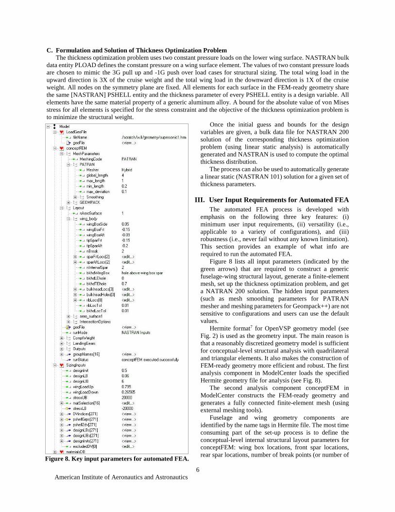
Figure 8 lists all input parameters (indicated by the
green arrows) that are required to construct a generic
fuselage-wing structural layout, generate a finite-element
mesh, set up the thickness optimization problem, and get
a NATRAN 200 solution. The hidden input parameters
(such as mesh smoothing parameters for PATRAN
mesher and meshing parameters for Geompack++) are not
sensitive to configurations and users can use the default
values.
Hermite format7 for OpenVSP geometry model (see
Fig. 2) is used as the geometry input. The main reason is
that a reasonably discretized geometry model is sufficient
for conceptual-level structural analysis with quadrilateral
and triangular elements. It also makes the construction of
FEM-ready geometry more efficient and robust. The first
analysis component in ModelCenter loads the specified
Hermite geometry file for analysis (see Fig. 8).
The second analysis component conceptFEM in
ModelCenter constructs the FEM-ready geometry and
generates a fully connected finite-element mesh (using
external meshing tools).
Fuselage and wing geometry components are
identified by the name tags in Hermite file. The most time
consuming part of the set-up process is to define the
conceptual-level internal structural layout parameters for
conceptFEM: wing box locations, front spar locations,
rear spar locations, number of break points (or number of
Figure 8. Key input parameters for automated FEA.

American Institute of Aeronautics and Astronautics
7
piecewise line segments) for spars, number of spars between front and rear spars, rib locations, frame/bulkhead
locations, and whether there are holes above or below wing box spars inside fuselage. All z coordinates for internal
structural components are calculated from the corresponding (x, y) locations.
A frame is defined as a bulkhead with a hole in the middle. Each parameter bulkheadLocs[i] specifies the actual x
location for a frame or bulkhead. If the parameter bulkheadHoles[i] is between 0 and 1, the corresponding structural
component at bulkheadLocs[i] is a frame and the ratio of cutout hole area to the cross-section area equals to
bulkheadHoles[i] (which must be less than 1). Otherwise, the corresponding structural component at bulkheadLocs[i]
is actually a solid wall.
Figure 9. Illustration of some layout parameters.
Side location of wing box is defined by its distance (wingBoxSide) from the intersection of fuselage and wing. If
wingBoxSide = 0, then the side of wing box in the half space y ≥ 0 is on the intersection curve. Front location of wing
box can be specified by the absolute distance (wingBoxFrt > 0) from LE or the distance (wingBoxFrt < 0) from LE in
terms of percentage of airfoil chord for side edge of wing box (see Fig. 9).
Other x locations for spars are defined similarly by either the absolute distance or the distance in terms of chord
length from a default reference location. All y locations (except wingBoxSide) are actual y coordinates for internal
components.
A useful parameter for supersonic configurations is nBreak, which is the number of break points for spars. The
underlying analysis code will calculate the angle between two consecutive segments of LE or TE; then find nBreak y
locations (see Fig. 9) where the calculated angles are smaller than the rest. The corresponding x locations for front and
rear spars at the selected y locations for break points are defined by sparFrtLocs (see Fig. 9) and sparAftLocs. The
front and rear spar locations at wing tip are defined by tipSparFrt and tipSparAft (see Fig. 9), respectively. Of course,
it is relatively easy to change the user interface to allow user-specified break points for front and rear spars. Equally
spaced spars between front and rear spars can be added to the layout by using input parameter nInternalSpar (under
conceptFEM→Layout→wing_body in Fig. 8). For example, two spars between front and rear spars are added to the
layout in Fig. 9 because nInternalSpar is 2.
Figure 10. Illustration of some predefined groups.
American Institute of Aeronautics and Astronautics
8
The current implementation arranges all surfaces in the FEM-ready geometry into 16 predefined groups (see Fig.
10): (1) top skin of wing, (2) bottom skin of wing, (3) spar inside wing, (4) spar inside fuselage, (5) rib between LE
and front spar, (6) rib between rear spar and TE, (7) rib between front and rear spars, (8) fuselage skin ahead of
wing/fuselage intersection, (9) fuselage skin behind wing/fuselage intersection, (10) fuselage skin along wing/fuselage
intersection, (11) fuselage cutout (by wing intersection) between LE and front spar, (12) fuselage cutout (by wing
intersection) between rear spar and TE, (13) fuselage cutout (by wing intersection) between front and rear spars, (14)
frame/bulkhead ahead of wing/fuselage intersection, (15) frame/bulkhead behind wing/fuselage intersection, and (16)
frame/bulkhead along wing/fuselage intersection. These groups allow easy assignments of material properties to all
elements by specifying matSelection parameters under SizingInputs in Fig. 8. Of course, these groups can be easily
redefined if more desirable grouping is needed.
The 16 groups listed above are further partitioned by intersection curves between different groups. After the
partition, any two connected surfaces share a common boundary curve. Each (color-coded) surface in the FEM-ready
geometry partition (see Figs. 4, 6, and 7) has one thickness design variable for thickness optimization. For example,
the mesh in Fig. 6 or Fig. 7 has 195 design variables for thickness optimization (i.e., there are 195 surfaces in the half
space y ≥ 0 to define the FEM-ready geometry in Fig. 4).
This approach avoids the set-up burden of defining design variables for thickness optimization, which could be
quite tedious and time consuming if the interface is not done properly.
The thickness optimization problem is to minimize the structural weight under a stress constraint. The stress
constraint forces the absolute value of von Mises stress on each element to be less than or equal to a given bound for
two constant pressure load conditions on the wing. To set up this simple thickness optimization problem, only six
input parameters (under SizingInputs in Fig. 8) are required: the bound for von Mises stress (stressUB), the minimum
gauge (designLB) for all shell elements, an optional upper bound (designUB) for thickness design variables, an initial
guess (designInit) for all thickness design variables, a constant upward pressure load on the wing (wingLoadUp), and
a constant downward pressure load on the wing (wingLoadDown).
The most time consuming part for set up of user input parameters is to find the appropriate parameters to define
the internal structural components. For any wing-body configuration, the thickness optimization problem can be set
up to run in minutes (instead of hours or days).
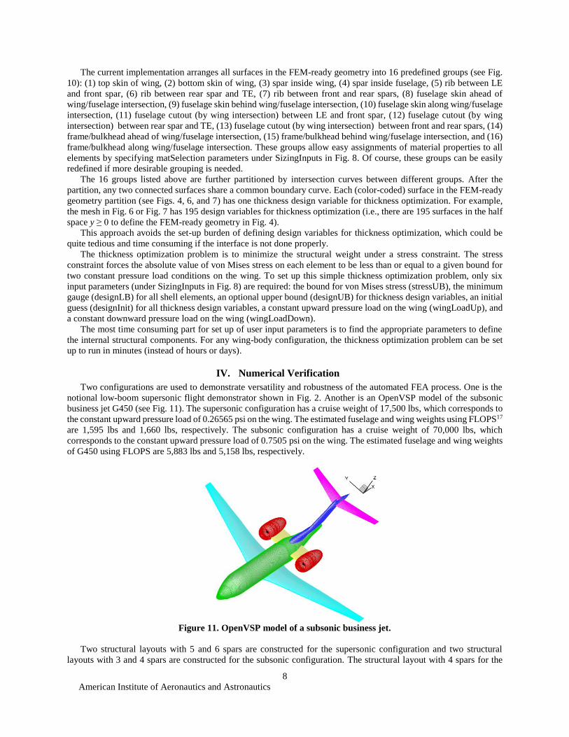
IV. Numerical Verification
Two configurations are used to demonstrate versatility and robustness of the automated FEA process. One is the
notional low-boom supersonic flight demonstrator shown in Fig. 2. Another is an OpenVSP model of the subsonic
business jet G450 (see Fig. 11). The supersonic configuration has a cruise weight of 17,500 lbs, which corresponds to
the constant upward pressure load of 0.26565 psi on the wing. The estimated fuselage and wing weights using FLOPS17
are 1,595 lbs and 1,660 lbs, respectively. The subsonic configuration has a cruise weight of 70,000 lbs, which
corresponds to the constant upward pressure load of 0.7505 psi on the wing. The estimated fuselage and wing weights
of G450 using FLOPS are 5,883 lbs and 5,158 lbs, respectively.
Figure 11. OpenVSP model of a subsonic business jet.
Two structural layouts with 5 and 6 spars are constructed for the supersonic configuration and two structural
layouts with 3 and 4 spars are constructed for the subsonic configuration. The structural layout with 4 spars for the
American Institute of Aeronautics and Astronautics
9
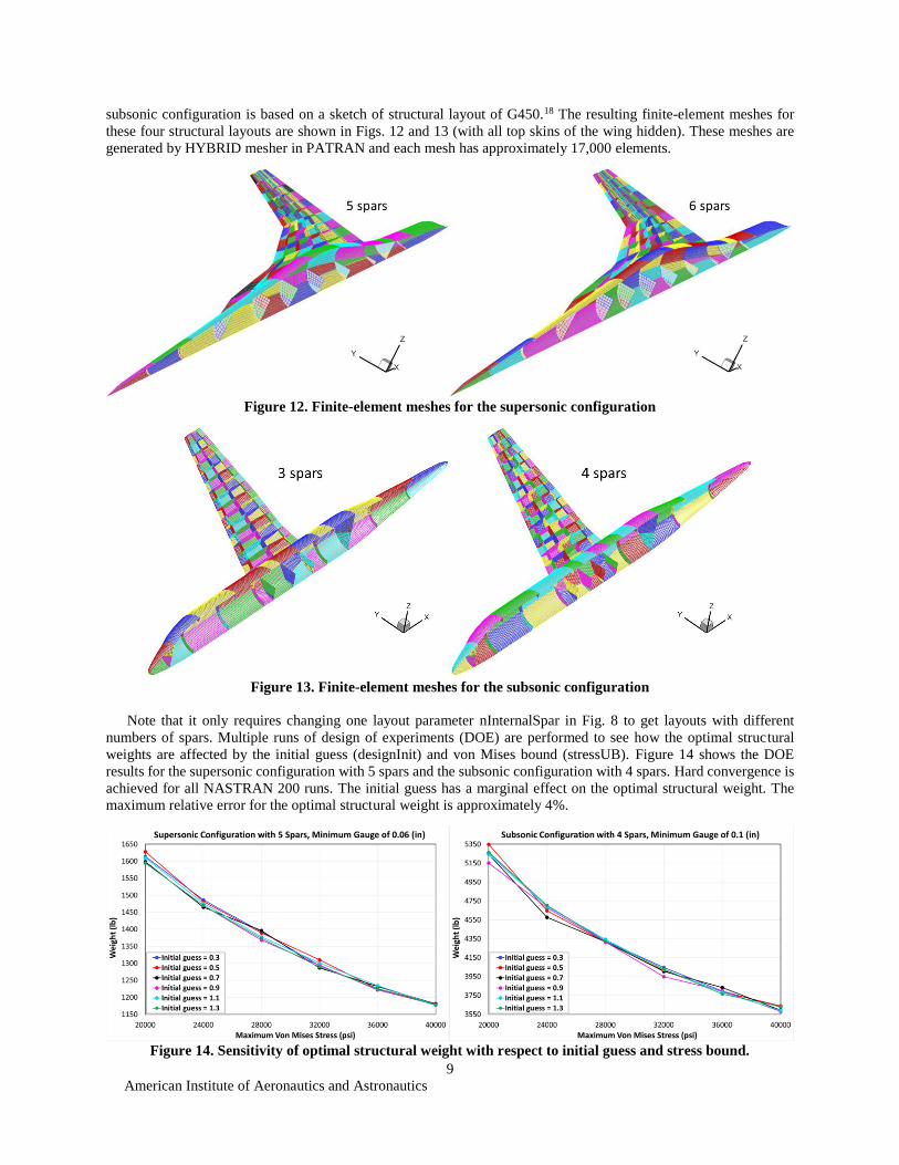
subsonic configuration is based on a sketch of structural layout of G450.18 The resulting finite-element meshes for
these four structural layouts are shown in Figs. 12 and 13 (with all top skins of the wing hidden). These meshes are
generated by HYBRID mesher in PATRAN and each mesh has approximately 17,000 elements.
Figure 12. Finite-element meshes for the supersonic configuration
Figure 13. Finite-element meshes for the subsonic configuration
Note that it only requires changing one layout parameter nInternalSpar in Fig. 8 to get layouts with different
numbers of spars. Multiple runs of design of experiments (DOE) are performed to see how the optimal structural
weights are affected by the initial guess (designInit) and von Mises bound (stressUB). Figure 14 shows the DOE
results for the supersonic configuration with 5 spars and the subsonic configuration with 4 spars. Hard convergence is
achieved for all NASTRAN 200 runs. The initial guess has a marginal effect on the optimal structural weight. The
maximum relative error for the optimal structural weight is approximately 4%.
Figure 14. Sensitivity of optimal structural weight with respect to initial guess and stress bound.
American Institute of Aeronautics and Astronautics
10
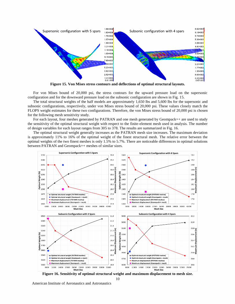
Figure 15. Von Mises stress contours and deflections of optimal structural layouts.
For von Mises bound of 20,000 psi, the stress contours for the upward pressure load on the supersonic
configuration and for the downward pressure load on the subsonic configuration are shown in Fig. 15.
The total structural weights of the half models are approximately 1,650 lbs and 5,600 lbs for the supersonic and
subsonic configurations, respectively, under von Mises stress bound of 20,000 psi. These values closely match the
FLOPS weight estimates for these two configurations. Therefore, the von Mises stress bound of 20,000 psi is chosen
for the following mesh sensitivity study.
For each layout, four meshes generated by PATRAN and one mesh generated by Geompack++ are used to study
the sensitivity of the optimal structural weight with respect to the finite-element mesh used in analysis. The number
of design variables for each layout ranges from 305 to 378. The results are summarized in Fig. 16.
The optimal structural weight generally increases as the PATRAN mesh size increases. The maximum deviation
is approximately 11% to 16% of the optimal weight of the finest structural mesh. The relative error between the
optimal weights of the two finest meshes is only 1.5% to 5.7%. There are noticeable differences in optimal solutions
between PATRAN and Geompack++ meshes of similar sizes.
Figure 16. Sensitivity of optimal structural weight and maximum displacement to mesh size.
American Institute of Aeronautics and Astronautics
11
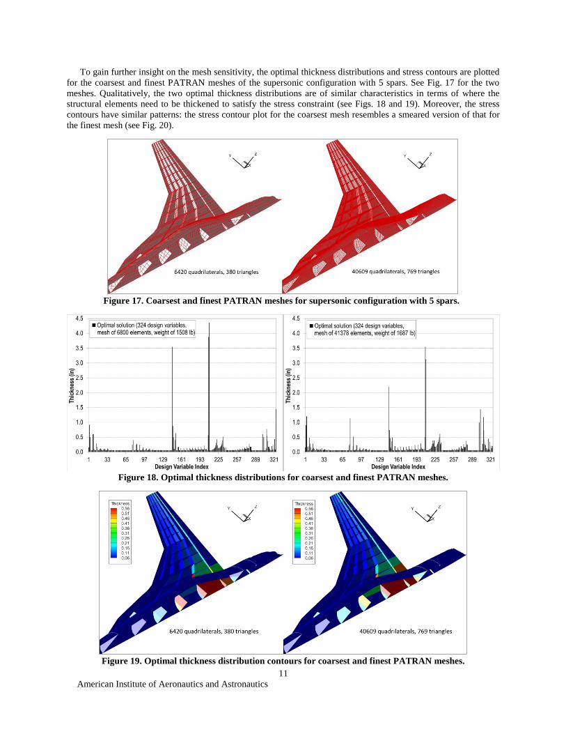
To gain further insight on the mesh sensitivity, the optimal thickness distributions and stress contours are plotted
for the coarsest and finest PATRAN meshes of the supersonic configuration with 5 spars. See Fig. 17 for the two
meshes. Qualitatively, the two optimal thickness distributions are of similar characteristics in terms of where the
structural elements need to be thickened to satisfy the stress constraint (see Figs. 18 and 19). Moreover, the stress
contours have similar patterns: the stress contour plot for the coarsest mesh resembles a smeared version of that for
the finest mesh (see Fig. 20).
Figure 17. Coarsest and finest PATRAN meshes for supersonic configuration with 5 spars.
Figure 18. Optimal thickness distributions for coarsest and finest PATRAN meshes.
Figure 19. Optimal thickness distribution contours for coarsest and finest PATRAN meshes.
American Institute of Aeronautics and Astronautics
12
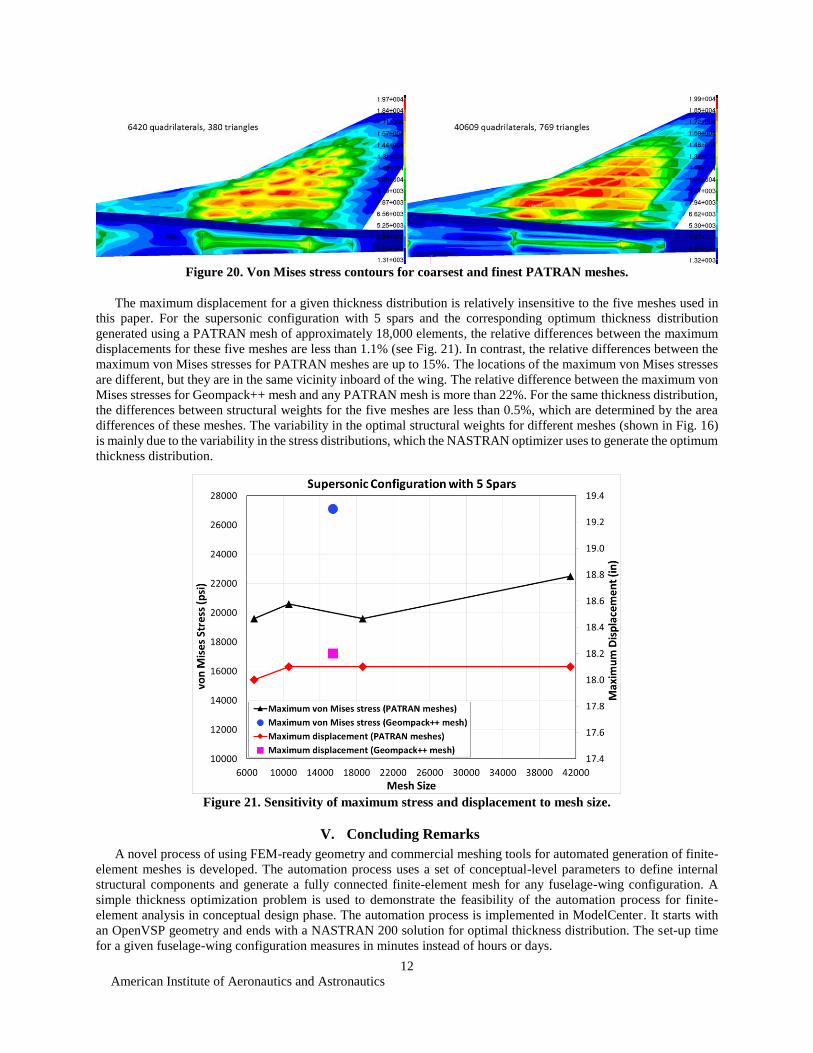
Figure 20. Von Mises stress contours for coarsest and finest PATRAN meshes.
The maximum displacement for a given thickness distribution is relatively insensitive to the five meshes used in
this paper. For the supersonic configuration with 5 spars and the corresponding optimum thickness distribution
generated using a PATRAN mesh of approximately 18,000 elements, the relative differences between the maximum
displacements for these five meshes are less than 1.1% (see Fig. 21). In contrast, the relative differences between the
maximum von Mises stresses for PATRAN meshes are up to 15%. The locations of the maximum von Mises stresses
are different, but they are in the same vicinity inboard of the wing. The relative difference between the maximum von
Mises stresses for Geompack++ mesh and any PATRAN mesh is more than 22%. For the same thickness distribution,
the differences between structural weights for the five meshes are less than 0.5%, which are determined by the area
differences of these meshes. The variability in the optimal structural weights for different meshes (shown in Fig. 16)
is mainly due to the variability in the stress distributions, which the NASTRAN optimizer uses to generate the optimum
thickness distribution.
Figure 21. Sensitivity of maximum stress and displacement to mesh size.
V. Concluding Remarks
A novel process of using FEM-ready geometry and commercial meshing tools for automated generation of finite-
element meshes is developed. The automation process uses a set of conceptual-level parameters to define internal
structural components and generate a fully connected finite-element mesh for any fuselage-wing configuration. A
simple thickness optimization problem is used to demonstrate the feasibility of the automation process for finite-
element analysis in conceptual design phase. The automation process is implemented in ModelCenter. It starts with
an OpenVSP geometry and ends with a NASTRAN 200 solution for optimal thickness distribution. The set-up time
for a given fuselage-wing configuration measures in minutes instead of hours or days.
American Institute of Aeronautics and Astronautics
13
Four structural layouts for supersonic and subsonic configurations are used to demonstrate versatility and
robustness of the automation process. A total of 20 meshes for the four different structural layouts are generated and
hard convergence of NASTRAN 200 solution is achieved for every mesh. Even though 11-16% differences in the
optimal structural weights of a given structural layout are observed for meshes of different sizes (approximately 6,800-
41,000 elements), the relative difference of the optimal structural weights for two finest meshes is within 5.7%.
Numerical discrepancy up to 4% in the optimal structural weight is observed due to the choice of initial guess for
design variables. All solutions for the same structural layout exhibit similar characteristics in terms of thickness
distribution and stress contour pattern. The stress contour plot for a coarse mesh resembles a smeared version of that
for a fine mesh. Using the same thickness distribution for the five meshes of the supersonic configuration with 5 spars,
the maximum displacements for these meshes differ by at most 1.1%, while noticeable differences between the
maximum von Mises stresses are observed.
In future, the automation process will be extended to include other aerodynamic surfaces (such as horizontal and
vertical tails), non-structural masses (such as landing gear, fuel, and engines), and aerodynamic load conditions in the
structural model for static aeroelastic analysis.
Acknowledgments
The authors would like to thank Karl Geiselhart at NASA Langley Research Center for providing the OpenVSP
model, FLOPS weight data, and reference info of the subsonic business jet G450. The authors would also like to
acknowledge James Fenbert at Analytical Mechanics Associates for instrumental comments on the paper. This work
is funded by NASA Commercial Supersonic Technology Project and NASA Transformational Tools & Technologies
Project.
References 1 Gern, F., “Update on HCDstruct - A Tool for Hybrid Wing Body Conceptual Design and Structural Optimization,”
AIAA 2015-2544, January 2015. 2 Laughlin, T., Corman, J., and Mavris D., “A Parametric and Physics-Based Approach to Structural Weight
Estimation of the Hybrid Wing Body Aircraft,” AIAA 2013-1082, January 2013. 3 NASTRAN, Version 2014.0, MSC Software, http://www.mscsoftware.com/product/msc-nastran [cited 2 March
2016]. 4 Eldred, L., Padula, S., and Li, W., “Enabling Rapid and Robust Structural Analysis,” NASA/TM-2015-218687,
2015. 5 RapidFEM, M4 Engineering, www.m4-engineering.com/software-creation/rapidfem [cited 2 March 2016]. 6 OpenVSP, Open Source, http://www.openvsp.org [cited 2 March 2016]. 7 Hahn, A., “Vehicle Sketch Pad: A Parametric Geometry Modeler for Conceptual Aircraft Design,” AIAA 2010-657,
January 2010. 8 Joe, B., “Geompack++ Meshing Operations,” Technical Report ZCS2012-01, Sep 2012. 9 Geompack++, Zhou Computing Services Inc., http://members.shaw.ca/bjoe [cited 2 March 2016]. 10 PATRAN, Version 2014 64-Bit, MSC Software, http://www.mscsoftware.com/product/patran [cited 2 March
2016]. 11 ModelCenter, Version 11.2, Phoenix Integration Inc., www.phoenix-int.com [cited 2 March 2016]. 12 Tecplot 360 EX, Version 2015 R1, Tecplot Inc., http://www.tecplot.com/products/tecplot-360 [cited 2 March 2016]. 13 Li, W., “Feasibility of Supersonic Aircraft Concepts for Low-Boom and Flight Trim Constraints,” AIAA 2015-
2581, June 2015. 14 de Boor, C., “A Practical Guide to Splines (Revised Edition),” Springer, New York, 2001. 15 Initial Graphics Exchange Specification, IGES 5.3, U.S. Product Data Association, 1996. 16 Joe, B., “Geompack++ File Formats for Regions and Meshes,” Technical Report ZCS2008-01, March 2008. 17 McCuller, L., “FLOPS User Guide,” NASA Langley Research Center, Hampton, Virginia, 2008. 18 Gulfstream G450 Sketch, http://www.flightglobalimages.com/p/241/gulfstream-g450-cutaway-poster-1571293.jpg
[cited 2 March 2016].