Embed Size (px)
Citation preview

Automated Remote Digital Imaging System (ARDIS):
Applications for Monitoring Dust Emissions in the Mojave Desert, California by
Richard K. Tigges, Stuart Sides, and Mark Ohms
Open File Report 01-230
This report is preliminary and has not been reviewed for conformity with the U. S. Geological Survey editorial standards or with the North American Stratigraphic Code. Any use of trade, product, or firm names is for descriptive purposes only and does not imply endorsement by the U. S. Government.
U. S. Department of the Interior U. S. Geological Survey, Denver Federal Center Denver, Colorado 80225

Introduction
The Automated Remote Digital Imaging System (ARDIS) is a means of automatically acquiring digital color images of dust storms. The images are used to identify the locations from which dust particles become airborne, the direction and intensity of the dust event, and the meteorological conditions at the time, in conjunction with Climate Impact Meteorological (CLIM-MET) sites (http://climchange.cr.usgs.gov/info/sw/clim-met/) in the area. The system is placed on top of a mountain to provide views down onto sites of dust emission at distances of 9 -20 km.
This system is made up of several off-the-shelf components, and several components that were designed and built in-house. Together they perform the task of automatically recording digital images from an unmanned remote location. The major components of this system are: Kodak DC265 digital zoom camera; Campbell CR10X datalogger; environmental enclosure; solar power system; FMA Direct 701R servo motor; a Handar 425 ultrasonic wind sensor; servo power control circuitry; camera scripts; and datalogger software. The system is modular in that the number of cameras that can be controlled is expandable from one to four.
The four-camera system (Fig. 1) has been in operation near Zzyzx, California in the Mojave desert since March 2, 2000.
Figure 1. Automated Remote Digital Imaging System, Mojave Desert, California.
This system has one camera that records a haze image twice daily, when sun angles are low. Each of the three remaining cameras is aimed at one of three remote CLIM-MET sites that are strategically placed in known dust-emitting areas. These sites gather meteorological data such as: wind speed, wind direction, air temperature, relative humidity, solar radiation, soil temperature, soil moisture, rainfall, and temperature gradient. The sites also monitor wind erosion using a sensor that records particle impacts in the saltation layer at 5 cm above the ground surface. All cameras are controlled by a datalogger. The datalogger directs the haze
2

camera (camera one) to take the twice-daily pictures. The datalogger also monitors wind speed and directs cameras two, three, and four to take images at 30-minute increments when the average wind speed is above a predetermined threshold, and at 15-minute increments when the average wind speed is above another (higher) predetermined threshold. Cameras two, three, and four each take a two-picture sequence, one wide-angle and one telephoto. The date/time and camera-name are superimposed near the bottom of each image. The times that camera one takes it’s twice-daily pictures, and the increments and wind-speed thresholds for cameras two, three, and four can be easily changed at the site without reprogramming. This is accomplished by making changes in a parameter entry table (within datalogger software) via keyboard communications to the datalogger. Program control of the cameras can be disabled through the keyboard, and each camera can then be manually controlled for maintenance purposes. Each camera records images on a 128-megabyte CompactFlash card, which is changed when nearly full. The datalogger logs all wind speed and direction data, as well as all camera commands and related date/time. It also logs the number of pictures taken and triggers a strobe light between the hours of 8 PM and 11 PM, when the flash cards are nearing capacity. This signals the need for a person to make the 90-minute climb up the mountain to change the flash cards.
To date, several hundred images (Fig. 2) have been successfully recorded by this system, controlled by the camera-site anemometer. The system is currently controlled by wind-speed measurements taken at one of the CLIM-MET sites, with commands transmitted by radio to the camera site.
Looking toward Baker - wide-angle Looking toward Baker - telephoto
Looking toward Baker – wide-angle Looking toward Baker - telephoto
Looking toward Balch – wide-angle Looking toward Balch - telephoto
3
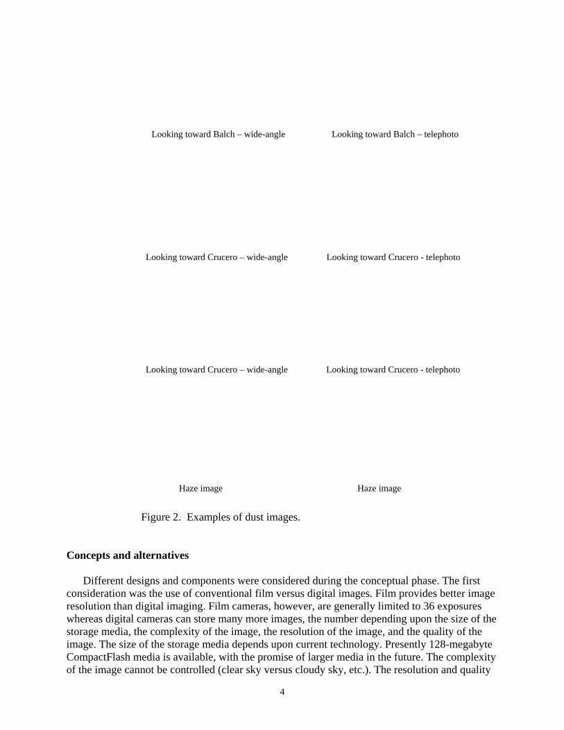
Looking toward Balch – wide-angle
Looking toward Crucero – wide-angle
Looking toward Crucero – wide-angle
Haze image
Figure 2. Examples of dust images.
Concepts and alternatives
Looking toward Balch – telephoto
Looking toward Crucero - telephoto
Looking toward Crucero - telephoto
Haze image
Different designs and components were considered during the conceptual phase. The first consideration was the use of conventional film versus digital images. Film provides better image resolution than digital imaging. Film cameras, however, are generally limited to 36 exposures whereas digital cameras can store many more images, the number depending upon the size of the storage media, the complexity of the image, the resolution of the image, and the quality of the image. The size of the storage media depends upon current technology. Presently 128-megabyte CompactFlash media is available, with the promise of larger media in the future. The complexity of the image cannot be controlled (clear sky versus cloudy sky, etc.). The resolution and quality
4

of the image can be controlled. High resolution and/or high quality result in larger file sizes than lower resolution and/or lower quality. Therefore, resolution and/or quality may have to be compromised depending on the storage media size and how often the media can be changed.
Digital still imagery can be accomplished with digital camcorders, with board cameras, and with off-the-shelf still cameras. Both resolution and storage capacity for the camcorder are low compared to the still cameras. The use of a board camera, and the many individual components necessary for a complete system, would be more expensive and would require considerably more development time than allowed in this situation. Digital off-the-shelf still cameras provide sufficient resolution for the project requirements along with built-in image storage, drivers, and remote interfaces.
The environment in which the camera(s) operate has temperatures ranging to >42o C (>100o F). Film may deteriorate in these conditions, whereas the digital storage media fares well. Other conditions such as rain, wind, and dust requires an environmental enclosure for any camera choice.
Film cameras offer some off-the-shelf systems such as those used for photographic bait stations (Kucera, and others 1995). One such system is the Trailmaster (www.trailmaster.com) which offers the ability to keep the camera alive (out of sleep mode) and to trigger the shutter via an infrared beam. The Trailmaster TM550 controller could be modified by the manufacturer to control the shutter using a switch closure rather than an infrared beam. Some digital systems offer more versatility than just a remote controlled trigger, including control over all camera functions and settings through the use of Digitatm scripts (www.flashpoint.com). A board camera system would require a more complex design to control the camera and thus a longer design and development phase.
Film systems consume considerably less power than a digital system. The digital system needs larger batteries and might require the use of a solar panel to keep batteries charged. Both systems would be generally the same in size, excluding the power system. Film camera systems generally would be less expensive than an equivalent digital system.
The need to record images in a variety of directions lends itself to a pan and tilt system. These systems are readily available for video surveillance systems and are for use with AC-line power. Battery drain would be quite high for a remote system. For a still camera system a better solution may be to use multiple cameras, each fixed to a given direction and tilt angle.
The final decision was to use a digital off-the-shelf still-camera system because of larger image storage media, concern for degradation of film images by temperatures, acceptable resolution, the highly desirable versatility afforded by Digitatm scripting, and less complexity than board cameras.
The second design-component consideration was the control system. This system essentially sets between a wind-speed instrument and the camera(s) and provides an interface to each. It also must maintain a system clock (year/day/hour/minute/second) and store environmental data such as wind speed, wind direction, and time of day when a camera or cameras are triggered. Decision making tasks must be performed, such as determining when to trigger a given camera based on predetermined criteria. The system must operate in a remote environment where no AC power is available and operate for long periods of time without operator intervention. The control system could be any of several form factors. The first factor is a datalogger. These devices are designed to interface to a number of sensors, have a system clock, are designed to log data from sensors, are programmable, and have a very low power usage that lends itself to remote situations. We use dataloggers in our CLIM-MET sites, so this approach gave us one step up in an already tight time schedule. It also made sense to use parts that are interchangeable with the CLIM-MET sites, reducing spare part inventories. We choose this approach. Another factor would be a personal computer. A standard desktop, laptop, or palmtop could do the job, but would suffer in the hot environment. Power usage would also be
5

prohibitive. A PC104 system might be a good candidate. This small one-card PC can be obtained in a variety of hardware and software configurations, and most have the capability to operate in harsh temperature environments. Most digital cameras that have a serial interface through which camera functions can be controlled come with the necessary software to control the camera through that interface. Such software is generally geared to run in an interactive windows environment that does not lend itself to a remote situation. Kodak does offer low-level interface specifications through their Developer Relations Program. Using one of these specifications, one could presumably control camera functions from a PC104 board using a stripped-down DOS operating system, or possibly using a micro-controller. This possibility, however, would require continuous power to the power-hungry cameras. Because of power constraints and a long development time for such a system, we chose not to use this approach.
The third design-component consideration was the power system. The components that require power are the camera, the datalogger, and the wind-speed instrument. The camera chosen for this project uses four AA size batteries. These batteries cannot provide power for the extended time periods desired. Thus, the camera requires an external power source. The camera requires 6 volts (NiMH, NiCD, or alkaline batteries) if powered from the battery compartment, or 8 volts if powered through the AC adapter input. The datalogger requires 12 volts, the wind-speed instrument 12 volts, and the RC servo 6 volts. The camera sites are in remote areas, with no available AC power. We chose to use rechargeable sealed lead-acid batteries. For a one-camera setup and relatively easy access, a small battery could be used. The battery could be replaced along with the compact flash media at regular intervals, and the removed battery recharged and ready for the next replacement cycle. For our multi-camera system, larger sealed lead-acid battery(s) are needed, along with a solar panel to provide daytime power and to charge the battery(s).
The fourth design-component considered was the type of wind-speed instrument. There are several common types: cup anemometers, propeller anemometers, hot-wire anemometers, and ultrasonic anemometers. Hot-wire anemometers have a high-power usage. Cup and propeller anemometers movement draws attention to the eye, and they have more potential for problems associated with moving parts in dusty environments. The ultrasonic anemometer is considerably higher in cost. The desire was to keep power usage down as much as possible, and to keep the camera site(s) as hidden as possible. With these considerations in mind, we opted for the ultrasonic anemometer.
Summary
The initial remote camera system supports four digital cameras. Camera number one takes a picture twice per day, at low sun angles, to record haze. The initial times are 9:25 AM and 2:25 PM. These times are site options, so that either or both can be easily changed at the site. Cameras two, three, and four take daylight pictures based upon wind-speed, now sensed at one of the monitored dust emission sites. The cameras are inactive during nighttime hours. The initial criteria are to trigger the cameras once per 30 minutes when the average wind speed is ≥ 20 miles per hour (32 kilometers/hour). Or, trigger once per 15 minutes when the wind speed is ≥ 25 miles per hour (40 kilometers/hour). Both the time intervals and the wind speeds are site options (easily changed on-site with no programming required). Two pictures are taken per trigger event by each of cameras two, three, and four. One picture is wide angle, and the other telephoto. The cameras imprint the date, time, and camera name on each image taken. Control is supplied with a Campbell CR10X datalogger, and it records the date, time, wind-speed, and wind-direction each time a camera is triggered. The datalogger also records the date, time, wind-speed, wind-direction, and the internal temperature of the datalogger once every two daylight hours. It is possible to break the system down such that individual components can make up four individual one-camera systems, or one system with any number of cameras up to four. Each individual
6

camera is housed in a separate environmental enclosure, allowing each to be aimed in a different direction. Each enclosure is capable of housing a Campbell CR10X datalogger such that it can act independently. In a multi-camera system only one datalogger is required. The initial system runs on battery power, with a solar panel to supply daytime power and to charge the battery(s). Two voltage levels are supplied: 12-volts for the datalogger and wind-speed instrument; and 6-volts for the camera and servo. The wind speed instrument is a Handar model 425 ultrasonic wind speed sensor using the analog wind-speed and wind-direction output. In February of 2001 a modification was made to control the cameras by wind speeds at one of the CLIM-MET sites, rather than wind speeds at the camera site. This was necessary because wind speeds at the mountaintop camera site can be quite different than at the dust emission areas. Camera 1 is still controlled by time parameters in the datalogger at the camera site. Cameras two, three, and four are still controlled by the camera site datalogger when a radio signal is received from the CLIMMET site. CLIM-MET site wind speeds are measured, and thresholds monitored in the same manner previously used at the mountaintop, and when thresholds are met a signal is sent to the camera site via radio transmitter.
System description
The imaging system
The camera of choice is the Kodak DC265 digital zoom camera. The camera has three settings for picture resolution and four settings for picture quality. Resolution is the number of pixels in each picture. The three resolutions are: high (1535 x 1024 pixels), medium (1152 x 768 pixels), and standard (768 x 512 pixels). With more pixels (or the higher the resolution), more space is used on the memory card. To save space, the pictures are compressed. When a picture is compressed, some color and detail information is discarded. More compression yields a lower quality picture. Less compression yields a better quality picture. “Super” compression provides the highest quality; “best” compresses the picture a small amount and has high quality; “better” compresses a picture more and has a lower quality; “good” compresses a picture the most and has the lowest quality. We found that high resolution and “best” compression mode suits our purpose well.
Digital cameras use several storage media. These include CompactFlash, Type II PC Card, and SmartMedia. The DC265 uses CompactFlash media, which at the time of this writing came in storage capacities as high as 128 megabytes. This media type was first introduced in 1994, weighs a half-ounce and is 43mm (1.7”) x 36mm (1.4”) x 3.3mm (0.13”). These cards are designed with solid-state-flash technology, a non-volatile storage solution that does not require a battery to retain data indefinitely. These cards have an operating shock rating of 2,000 Gs, which is equivalent to a 10-foot drop. CompactFlash cards support both 3.3V and 5V operation and any card can operate at either voltage. These cards have a built-in controller, eliminating the need for a controller in the host device. Data are protected by built-in-dynamic defect management and error-correction technologies. Using the resolution and compression mode/quality settings mentioned above, the camera can typically store more than 200 pictures on a 128 megabyte CompactFlash card.
The DC265 has Digitatm scripting capabilities. Digita Script is a development language for Digita-based devices (such as the Kodak DC265 camera) developed by FlashPoint Technology. This language provides a series of commands, expressed in plain ASCII text, that can be interpreted by system software in the camera. These scripts can extend camera functionality and can automate already existing camera functions. These scripts are text files, and have a filename of the format XXXXXXXX.CSM. The first eight characters (XXXXXXXX) can be any letter a-z, number 0-9, or the underscore (_) character. There can be from 1-8 characters before the
7

period (.). The last 3 characters must always be CSM. These are the same rules used by the DOS operating system for naming files. Scripts can be written using any text editor, or a word processor capable of saving files as text files. Our script (see appendix A) is stored with filename STARTUP.CSM in the “system” folder on the CompactFlash card. This means that the script will be automatically run when the camera is powered on.
The Kodak DC265 saves pictures in JPEG (JPG) format. JPEG (Joint Photographic Experts Group) is a standardized image compression mechanism. JPEG ompresses either full-color or gray-scale images. JPEG is “lossy,” meaning the decompressed image isn’t quite the same as the original. JPEG is designed to exploit known limitations of the human eye, notably the fact that small color changes are perceived less accurately than small changes in brightness.
The Kodak DC265 camera can superimpose the date/time and/or user defined text on an image. Images taken with ARDIS have the date/time superimposed on the lower right portion of the image, and the camera name superimposed on the lower left portion of the image.
Focus, flash, and all other camera functions can be controlled manually, using a serial interface, or using scripts. In this design, the camera must be protected from environmental conditions such as wind, rain, and dust. Such protection requires an enclosure with a glass-covered opening. A means to control the camera focus is required. An auto-focus setting might focus on the glass itself, especially if raindrops or dust are on the glass. The only Digitatm
scripting camera available with the capability to control the focus (at the time of this design) was the Kodak DC265. The ARDIS script sets the focus to manual and infinity. Also, it is important that the flash be turned off (not possible with some cameras), and that the camera has an auto-exposure feature to control aperture and speed. The ARDIS script sets the flash to “off” and the auto-exposure mode is used.
The control system
The control system consists of (1) the Campbell CR10X datalogger, (2) the program to control the datalogger (see appendix B), (3) FMA Direct 701R servo motor (one per camera, appendix C), (4) Teflon cam attached to the servo motor (see appendix C), and (5) Handar 425 ultrasonic wind sensor. The system has four-cameras with camera #1 recording images to detect haze twice daily. This camera is cycled each morning and afternoon when the sun is at a low angle (when haze is most visible.) The times are 09:25 and 14:25. Individual camera operating times are staggered to conserve power. Cameras two, three, and four record two images each when wind conditions indicate the possibility of a dust storm. The datalogger samples the wind sensor once per minute and keeps a 15-sample (15-minute) running average of the wind speed. This running average is checked at 15-minute intervals (during daylight hours), and if the average is equal to or above a predetermined threshold the servo for camera #2 cycles and the camera runs through its startup script, records images, and powers down. Two minutes later the servo for camera #3 is cycled, and another two minutes later the same is done for camera #4. The cameras are cycled two-minutes apart so there is never more than one camera powered on at a time. This keeps the current drawn from the power supply at any given time as low as possible. If the 15-minute interval check finds the wind-speed below the preset threshold (no cameras triggered), then a 30-minute interval checks the wind speed in a similar manner using a lower wind-speed threshold and the cameras are cycled if these conditions are met. During nighttime hours camera operation is inhibited and the system performs only basic housekeeping functions.
8

Camera control
There are two facets to camera control. The first is applying power to the camera when it is determined by the datalogger that images are to be taken. The second is control of all other camera functions via a script.
Applying power
Power to the camera must be supplied either through batteries in the battery compartment, or through an AC adapter connector. Power is applied to the camera by intermittently depressing a power button. This is accomplished by turning a cam with a Radio Control (RC) servo. The cam rotates clockwise to intermittently depress the power button, then rotates in the reverse direction (counterclockwise) to the starting position (see appendix C). ARDIS supplies power to the camera battery compartment through “dummy” batteries (see appendix D).
Camera scripts
The camera functions are controlled via a “Startup” script (see appendix A) placed in the “system” folder contained on the camera storage media (CompactFlash card.) This script file runs upon power-up, sets up camera functions, commands the camera to record an image, resets camera functions and moves the lens to a new zoom position. The script command set includes a power-off command, so when all tasks for a given image recording session are complete, the camera is powered off via that script command. It is necessary to keep the cameras powered down when not in use for two reasons. First, the power-up sequence causes the “startup” script to run. Second, the camera draws considerable current when operating, unacceptable in a remote, battery-powered situation.
The Environmental Enclosure
Each camera is mounted in an individual enclosure; a datalogger can also be mounted in each enclosure. With a single-camera installation, a datalogger and camera are mounted in a single enclosure. In a multi-camera installation, a datalogger is mounted in only one of the enclosures. Each enclosure can be configured as master (contains the datalogger) or slave (receives datalogger signals from another enclosure). Each enclosure contains two fuses: a 1-amp fuse for 6-volt power to the camera and servo, and a ½-amp fuse for 12-volt power to the datalogger and ultrasonic-wind speed instrument.
9
Acknowledgments
Pat Chavez provided the inspiration to do this work. Rich Reynolds supported this work and “had the faith”. Dave MacKinnon designed an ingenious method for anchoring guy wires. We thank Pat Chavez, Dave MacKinnon, Rich Reynolds, and Marith Reheis for hauling equipment up the mountain for the initial installation, and Miguel Velasco for hauling equipment up and down the mountain when modifications were made. Many thanks to Rob Fulton who has made many long hot trips up the mountain to service the cameras, and the USGS Earth Surface Dynamics Program for supporting and providing funding for this work. Thanks to the FMA Direct Engineering staff for information on servo use, and Andrew Kirk and Rich Robinson of Flashpoint Technologies for their technical support. We also thank Deborah Lee Soltesz who steadfastly maintains all of the images and metadata.
References
Kuccera, T., Soukkala, A., Zielinski, W. 1995. Photographic Bait Stations, in Zielinski, W., Kucera, T., American Marten, Fisher, Lynx, and Wolverine: Survey Methods for Their Detection. U.S. Department of Agriculture Forest Service General Technical Report PSW-GTR-157; 27 p.
Sources of Information
Flashpoint Technology : Home page - www.flashpoint.com
Digita Camera - News, FAQs, scripts, links | www.digitacamera.com
Digita developers – a site for developers of Digitatm script | www.digitadev.com
Kodak:
Kodak Developer Relations | www.kodak.com/US/en/developers/index.jhtml
Unofficial Kodak DC260 FAQ | www.trix.com/dc260
Trailmaster:
Information on Infrared trail monitoring systems | www.trailmaster.com
General digital camera information:
Curtin’s Short Courses in Digital Photography | www.shortcources.com
Datalogger and wind speed sensor information:
Campbell Scientific CR10X Measurement and Control Module Operators Manual
Handar 425 Ultrasonic Wind Sensor Manual
10
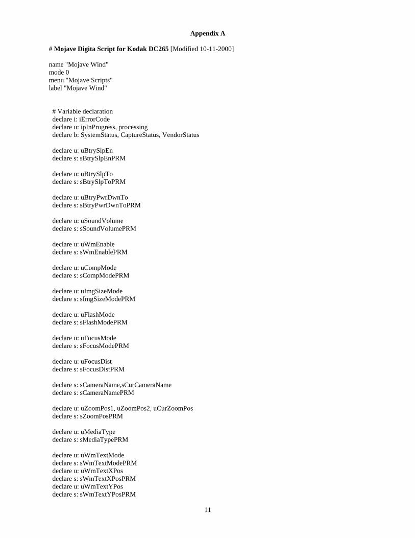
Appendix A
# Mojave Digita Script for Kodak DC265 [Modified 10-11-2000]
name "Mojave Wind" mode 0 menu "Mojave Scripts" label "Mojave Wind"
# Variable declaration declare i: iErrorCode declare u: ipInProgress, processing declare b: SystemStatus, CaptureStatus, VendorStatus
declare u: uBtrySlpEn declare s: sBtrySlpEnPRM
declare u: uBtrySlpTo declare s: sBtrySlpToPRM
declare u: uBtryPwrDwnTo declare s: sBtryPwrDwnToPRM
declare u: uSoundVolume declare s: sSoundVolumePRM
declare u: uWmEnable declare s: sWmEnablePRM
declare u: uCompMode declare s: sCompModePRM
declare u: uImgSizeMode declare s: sImgSizeModePRM
declare u: uFlashMode declare s: sFlashModePRM
declare u: uFocusMode declare s: sFocusModePRM
declare u: uFocusDistdeclare s: sFocusDistPRM
declare s: sCameraName,sCurCameraNamedeclare s: sCameraNamePRM
declare u: uZoomPos1, uZoomPos2, uCurZoomPos declare s: sZoomPosPRM
declare u: uMediaType declare s: sMediaTypePRM
declare u: uWmTextMode declare s: sWmTextModePRM declare u: uWmTextXPos declare s: sWmTextXPosPRM declare u: uWmTextYPos declare s: sWmTextYPosPRM
11
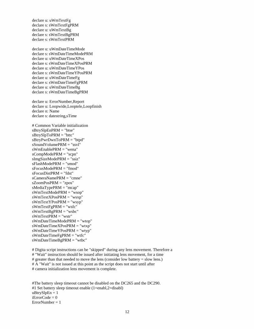
declare u: uWmTextFg declare s: sWmTextFgPRM declare u: uWmTextBg declare s: sWmTextBgPRM declare s: sWmTextPRM
declare u: uWmDateTimeMode declare s: sWmDateTimeModePRM declare u: uWmDateTimeXPos declare s: sWmDateTimeXPosPRM declare u: uWmDateTimeYPos declare s: sWmDateTimeYPosPRM declare u: uWmDateTimeFg declare s: sWmDateTimeFgPRM declare u: uWmDateTimeBg declare s: sWmDateTimeBgPRM
declare u: ErrorNumber,Reportdeclare u: Loopwide,Looptele,Loopfinish declare n: Namedeclare s: datestring,sTime
# Common Variable initializationsBtrySlpEnPRM = "btse" sBtrySlpToPRM = "bttc" sBtryPwrDwnToPRM = "btpd" sSoundVolumePRM = "ssvl"sWmEnablePRM = "wena" sCompModePRM = "scpn" sImgSizeModePRM = "ssiz" sFlashModePRM = "smod" sFocusModePRM = "fmod" sFocusDistPRM = "fdst"sCameraNamePRM = "cmne" sZoomPosPRM = "zpos" sMediaTypePRM = "mcap" sWmTextModePRM = "wsop" sWmTextXPosPRM = "wsxp" sWmTextYPosPRM = "wsyp" sWmTextFgPRM = "wsfc" sWmTextBgPRM = "wsbc" sWmTextPRM = "wstr" sWmDateTimeModePRM = "wtop" sWmDateTimeXPosPRM = "wtxp" sWmDateTimeYPosPRM = "wtyp" sWmDateTimeFgPRM = "wtfc" sWmDateTimeBgPRM = "wtbc"
# Digita script instructions can be "skipped" during any lens movement. Therefore a # "Wait" instruction should be issued after initiating lens movement, for a time # greater than that needed to move the lens (consider low battery = slow lens.) # A "Wait" is not issued at this point as the script does not start until after # camera initialization lens movement is complete.
#The battery sleep timeout cannot be disabled on the DC265 and the DC290. #1 Set battery sleep timeout enable (1=enabl,2=disabl) uBtrySlpEn = 1iErrorCode = 0 ErrorNumber = 1
12
iErrorCode = SetCameraState (sBtrySlpEnPRM, uBtrySlpEn) if iErrorCode !=0
goto ErrorProc end
#This script should run about 1 minute, so set the battery sleep timeout to 2-minutes. #2 Set battery sleep timeout (seconds) uBtrySlpTo = 120 iErrorCode = 0 ErrorNumber = 2 iErrorCode = SetCameraState (sBtrySlpToPRM, uBtrySlpTo) if iErrorCode !=0
goto ErrorProc end
#If the camera has gone to sleep there is a problem, so power down ASAP. #3 Set battery power down time out (seconds) uBtryPwrDwnTo = 5 iErrorCode = 0 ErrorNumber = 3 iErrorCode = SetCameraState (sBtryPwrDwnToPRM, uBtryPwrDwnTo) if iErrorCode !=0
goto ErrorProc end
#4 Set camera NamesCameraName = "Balch" iErrorCode= 0 ErrorNumber = 4 iErrorCode = SetCameraState (sCameraNamePRM, sCameraName) if iErrorCode !=0
goto ErrorProc end
#5 Check camera nameErrorNumber = 5 GetCameraState (sCameraNamePRM, sCurCameraName)if sCurCameraName != sCameraName
goto ErrorProc end
#6 Set sound volume (0=off,1=on) uSoundVolume = 0 iErrorCode = 0 ErrorNumber = 6 iErrorCode = SetCameraState (sSoundVolumePRM, uSoundVolume) if iErrorCode !=0
goto ErrorProc end
# Set up the date/time/camera-name as water mark
#7 Water mark (0b1000=8=logo,0b0100=4=text,0b0010=2=time,0b0001=1=date) uWmEnable = 7 iErrorCode = 0 ErrorNumber = 7 iErrorCode = SetCameraState (sWmEnablePRM,uWmEnable) if iErrorCode != 0
goto ErrorProc end
13
#8 Set date/time watermark positionuWmDateTimeXPos = 100 iErrorCode = 0 ErrorNumber = 8 iErrorCode = SetCameraState (sWmDateTimeXPosPRM,uWmDateTimeXPos) if iErrorCode != 0
goto ErrorProc end
#9 uWmDateTimeYPos = 100 iErrorCode = 0 ErrorNumber = 9 iErrorCode = SetCameraState (sWmDateTimeYPosPRM,uWmDateTimeYPos) if iErrorCode != 0
goto ErrorProc end
#10 Set date/time watermark operation (0=opaque,1=BG transparent) uWmDateTimeMode = 0 iErrorCode = 0 ErrorNumber = 10 iErrorCode = SetCameraState (sWmDateTimeModePRM,uWmDateTimeMode) if iErrorCode != 0
goto ErrorProc end
#11 Set date/time watermark Forground (0=wt,1=rd,2=grn,3=blu,4=cyn # 5=mag,6=ylw,7=blk) uWmDateTimeFg = 0 iErrorCode = 0 ErrorNumber = 11 iErrorCode = SetCameraState (sWmDateTimeFgPRM,uWmDateTimeFg)if iErrorCode != 0
goto ErrorProc end
#12 Set date/time watermark Background (0=wt,1=rd,2=grn,3=blu,4=cyn # 5=mag,6=ylw,7=blk) uWmDateTimeBg = 7 iErrorCode = 0 ErrorNumber = 12 iErrorCode = SetCameraState (sWmDateTimeBgPRM,uWmDateTimeBg)if iErrorCode != 0
goto ErrorProc end
#13 Set text watermark position uWmTextXPos = 0 iErrorCode = 0 ErrorNumber = 13 iErrorCode = SetCameraState (sWmTextXPosPRM,uWmTextXPos) if iErrorCode != 0
goto ErrorProc end
#14 uWmTextYPos = 100 iErrorCode = 0
14
ErrorNumber = 14 iErrorCode = SetCameraState (sWmTextYPosPRM,uWmTextYPos) if iErrorCode != 0
goto ErrorProc end
#15 Set text watermark operation (0=opaque,1=BG transparent)uWmTextMode = 0 iErrorCode = 0 ErrorNumber = 15 iErrorCode = SetCameraState (sWmTextModePRM,uWmTextMode) if iErrorCode != 0
goto ErrorProc end
#16 Set text watermark Forground (0=wt,1=rd,2=grn,3=blu,4=cyn# 5=mag,6=ylw,7=blk) uWmTextFg = 0 iErrorCode = 0 ErrorNumber = 16 iErrorCode = SetCameraState (sWmTextFgPRM,uWmTextFg)if iErrorCode != 0
goto ErrorProc end
#17 Set text watermark Background (0=wt,1=rd,2=grn,3=blu,4=cyn# 5=mag,6=ylw,7=blk) uWmTextBg = 7 iErrorCode = 0 ErrorNumber = 17 iErrorCode = SetCameraState (sWmTextBgPRM,uWmTextBg)if iErrorCode != 0
goto ErrorProc end
#18 Get camera name and set water mark string GetCameraState (sCameraNamePRM, sCurCameraName)iErrorCode = 0 ErrorNumber = 18 iErrorCode = SetCameraState (sWmTextPRM,sCurCameraName) if iErrorCode != 0
goto ErrorProc end
#19 Set Compression mode/Quality (2=good,3=better,4=best,5=super) uCompMode = 4 iErrorCode = 0 ErrorNumber = 19 iErrorCode = SetCameraState (sCompModePRM, uCompMode) if iErrorCode !=0
goto ErrorProc end
#20 Set still image capture size (1=full,2=1/4,3=1/16) uImgSizeMode = 1 iErrorCode = 0 ErrorNumber = 20 iErrorCode = SetCameraState (sImgSizeModePRM, uImgSizeMode) if iErrorCode !=0
goto ErrorProc
15
end
#21 Set flash mode (1=off,2=auto,3=fill,5=sync) uFlashMode = 1 iErrorCode = 0 ErrorNumber = 21 iErrorCode = SetCameraState (sFlashModePRM, uFlashMode) if iErrorCode !=0
goto ErrorProc end
#22 Set focus mode (1=auto,3=manual)uFocusMode = 3 iErrorCode = 0 ErrorNumber = 22 iErrorCode = SetCameraState (sFocusModePRM, uFocusMode) if iErrorCode !=0
goto ErrorProc end
#23 Set focus distance (50 to 65535) uFocusDist = 65535 iErrorCode= 0 ErrorNumber = 23 iErrorCode = SetCameraState (sFocusDistPRM, uFocusDist) if iErrorCode !=0
goto ErrorProc end
#24 Set time format to HH:MM:SS iErrorCode= 0 ErrorNumber = 24 iErrorCode = SetCameraState ("tfmt", 2)if iErrorCode !=0
goto ErrorProc end
#25 Set zoom position to wideangle (100 to 300) uZoomPos1 = 100 iErrorCode= 0 ErrorNumber = 25 iErrorCode = SetCameraState (sZoomPosPRM, uZoomPos1) if iErrorCode !=0
goto ErrorProc end
# Wait for the lens to complete movement.
Wait (4000)
# Wait for any image processing to complete.
ipInProgress = 0x10000000 Loopwide = 0 WIDETOP:
# Record system status every 1/2 second until the IPIP flag resets.
GetCameraStatus (SystemStatus, CaptureStatus, VendorStatus) GetDateString (datestring)
16
GetTimeString (sTime) FileOpen (2,"System/report.txt",1,Report) WriteLine (Report,"SystemStatus= ",SystemStatus," Loopwide= ",Loopwide," Date/time= ",datestring," ",sTime) FileClose (Report)
# Check the IPIP flag, loop if not reset.
processing = SystemStatus & ipInProgress if processing == ipInProgress
Loopwide = Loopwide + 1 Wait (500) goto WIDETOP
end
# Capture the wideangle picture
iErrorCode= 0 SetCaptureMode (still) iErrorCode = StartCapture ()
if iErrorCode == 0 FileOpen (2,"System/report.txt",1,Report) WriteLine (Report,"Wideangle image capture succeeded.") FileClose (Report)
end
if iErrorCode != 0 FileOpen (2,"System/report.txt",1,Report) WriteLine (Report,"Wideangle image capture failed. Error ", iErrorCode) FileClose (Report)
end
# Wait for image processing to complete.
ipInProgress = 0x10000000 Looptele = 0 TELETOP:
# Record system status every 1/2 second until the IPIP flag resets.
GetCameraStatus (SystemStatus, CaptureStatus, VendorStatus) GetDateString (datestring) GetTimeString (sTime) FileOpen (2,"System/report.txt",1,Report) WriteLine (Report,"SystemStatus= ",SystemStatus," Looptele= ",Looptele," Date/time= ",datestring," ",sTime) FileClose (Report)
# Check the IPIP flag, loop if not reset.
processing = SystemStatus & ipInProgress if processing == ipInProgress
Looptele = Looptele + 1 Wait (500) goto TELETOP
end
# Record completion of the wideangle capture and image processing.
FileOpen (2,"System/report.txt",1,Report) WriteLine (Report,"Wideangle image processing complete."," SystemStatus= ",SystemStatus)
17
FileClose (Report)
#26 Set zoom position to telephoto # Zoom position 2 (100 to 300) uZoomPos2 = 300 iErrorCode= 0 ErrorNumber = 26 iErrorCode = SetCameraState (sZoomPosPRM, uZoomPos2) if iErrorCode !=0
goto ErrorProc end
# Wait for the lens to complete movement.
Wait (4000)
# Capture the telephoto picture
iErrorCode= 0 SetCaptureMode (still) iErrorCode = StartCapture ()
if iErrorCode == 0 FileOpen (2,"System/report.txt",1,Report) WriteLine (Report,"Telephoto image capture succeeded.") FileClose (Report)
end
if iErrorCode != 0 FileOpen (2,"System/report.txt",1,Report) WriteLine (Report,"Telephoto image capture failed. Error ", iErrorCode) FileClose (Report)
end
# Wait for image processing to complete.
ipInProgress = 0x10000000 Loopfinish = 0 FINISHTOP:
# Record system status every 1/2 second until the IPIP flag resets.
GetCameraStatus (SystemStatus, CaptureStatus, VendorStatus) GetDateString (datestring) GetTimeString (sTime) FileOpen (2,"System/report.txt",1,Report) WriteLine (Report,"SystemStatus= ",SystemStatus," Loopfinish= ",Loopfinish," Date/time= ",datestring,"
",sTime) FileClose (Report)
# Check the IPIP flag, loop if not reset.
processing = SystemStatus & ipInProgress if processing == ipInProgress
Loopfinish = Loopfinish + 1 Wait (500) goto FINISHTOP
end
# Record completion of the telephoto capture and image processing.
18
FileOpen (2,"System/report.txt",1,Report) WriteLine (Report,"Telephoto image processing complete."," SystemStatus= ",SystemStatus) FileClose (Report)
goto Done
#----------------------------------------------------------Done:
FileOpen (2,"System/report.txt",1,Report) WriteLine (Report,"Two picture sequence complete.") FileClose (Report)
SetPowerMode ()
exitscript
#----------------------------------------------------------ErrorProc:
FileOpen (2,"System/report.txt",1,Report) WriteLine (Report,"Error number ",ErrorNumber,"occured.") WriteLine (Report,"iErrorCode = ",iErrorCode) FileClose (Report)
SetPowerMode ()
exitscript #----------------------------------------------------------
Although this program has been used by the U.S. Geological Survey, no warranty, expressed or implied, is made by the USGS as to the accuracy and functioning of the program and related program material nor shall the fact of distribution constitute any such warranty, and no responsibility is assumed by the USGS in connection therewith.
19
Appendix B
;{CR10X} ; ; ; ;Last revised 04/25/2000 at 20:00 ; ; ;ZYZZXCA1.CSI ; ; ;The clock shall be set to "Daylight savings time" to match the CLIM-MET sites. ; ;This means that during standard time periods (Last Sunday in October to first Sunday in;April), 1 hour must be added when setting the clock (*5). ; ;Data will be stored during daylight hours using unique ID's as follows: ; ; XXY where XX = site ID (50-99) and Y = data ID ; ; camera 1 = 1 if normal cycle or 6 if maintenance cycle ; camera 2 = 2 if normal cycle or 7 if maintenance cycle ; camera 3 = 3 if normal cycle or 8 if maintenance cycle ; camera 4 = 4 if normal cycle or 9 if maintenance cycle ; ; 2-hr data = 5 ; ; [Example: site 50 and camera 3 normal cycle data = 503]; ;Camera 1 (twice daily pictures) - ID = 501/506 - Y,D,Hr/min - Wind speed running average ; ;Cameras 2,3,4 (pictures taken when wind speed threshold(s) are reached) ; ; Camera 2 - ID = 502/507 - Y,D,Hr/min - Wind speed running average ; Camera 3 - ID = 503/508 - Y,D,Hr/min; Camera 4 - ID = 504/509 - Y,D,Hr/min; ;Every two hours - ID = 505 - Y,D,Hr/min - Wind vector - Internal temp. - Battery min/max ; ; ;Control port usage:; ;Control port 1 = Pulse string to camera #1 servo. ; ;Control port 2 = Pulse string to camera #2 servo. ; ;Control port 3 = Pulse string to camera #3 servo. ; ;Control port 4 = Pulse string to camera #4 servo. ; ;Control port 5 = Control switched +12 volts to ultrasonic anemometer. ; ;Control port 6 = Control switching +6 volts to all servos. ; ;Control port 7 = ; ;Control port 8 = Control a strobe light. ;
20
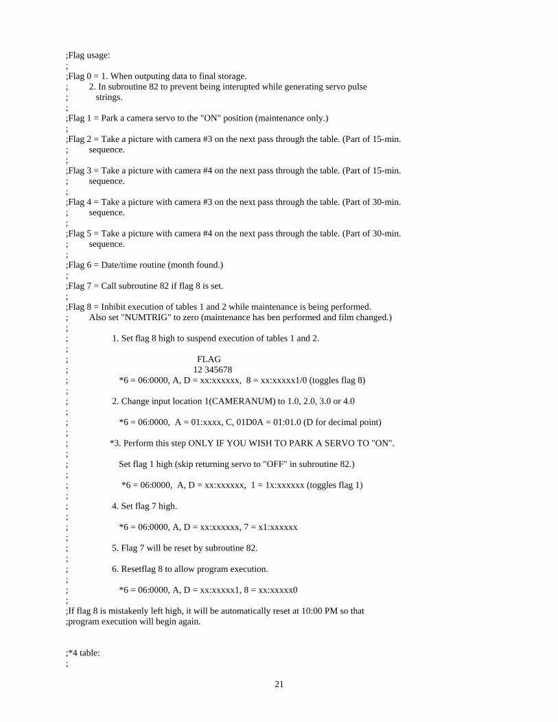
;Flag usage: ; ;Flag 0 = 1. When outputing data to final storage. ; 2. In subroutine 82 to prevent being interupted while generating servo pulse ; strings. ; ;Flag 1 = Park a camera servo to the "ON" position (maintenance only.) ; ;Flag 2 = Take a picture with camera #3 on the next pass through the table. (Part of 15-min. ; sequence. ; ;Flag 3 = Take a picture with camera #4 on the next pass through the table. (Part of 15-min. ; sequence. ; ;Flag 4 = Take a picture with camera #3 on the next pass through the table. (Part of 30-min. ; sequence. ; ;Flag 5 = Take a picture with camera #4 on the next pass through the table. (Part of 30-min. ; sequence. ; ;Flag 6 = Date/time routine (month found.) ; ;Flag 7 = Call subroutine 82 if flag 8 is set. ; ;Flag 8 = Inhibit execution of tables 1 and 2 while maintenance is being performed. ; Also set "NUMTRIG" to zero (maintenance has ben performed and film changed.) ; ; 1. Set flag 8 high to suspend execution of tables 1 and 2. ; ; FLAG ; 12 345678 ; *6 = 06:0000, A, D = xx:xxxxxx, 8 = xx:xxxxx1/0 (toggles flag 8) ; ; 2. Change input location 1(CAMERANUM) to 1.0, 2.0, 3.0 or 4.0 ; ; *6 = 06:0000, A = 01:xxxx, C, 01D0A = 01:01.0 (D for decimal point) ; ; *3. Perform this step ONLY IF YOU WISH TO PARK A SERVO TO "ON". ; ; Set flag 1 high (skip returning servo to "OFF" in subroutine 82.) ; ; *6 = 06:0000, A, D = xx:xxxxxx, 1 = 1x:xxxxxx (toggles flag 1) ; ; 4. Set flag 7 high. ; ; *6 = 06:0000, A, D = xx:xxxxxx, 7 = x1:xxxxxx ; ; 5. Flag 7 will be reset by subroutine 82.; ; 6. Resetflag 8 to allow program execution. ; ; *6 = 06:0000, A, D = xx:xxxxx1, 8 = xx:xxxxx0 ; ;If flag 8 is mistakenly left high, it will be automatically reset at 10:00 PM so that ;program execution will begin again.
;*4 table:;
21
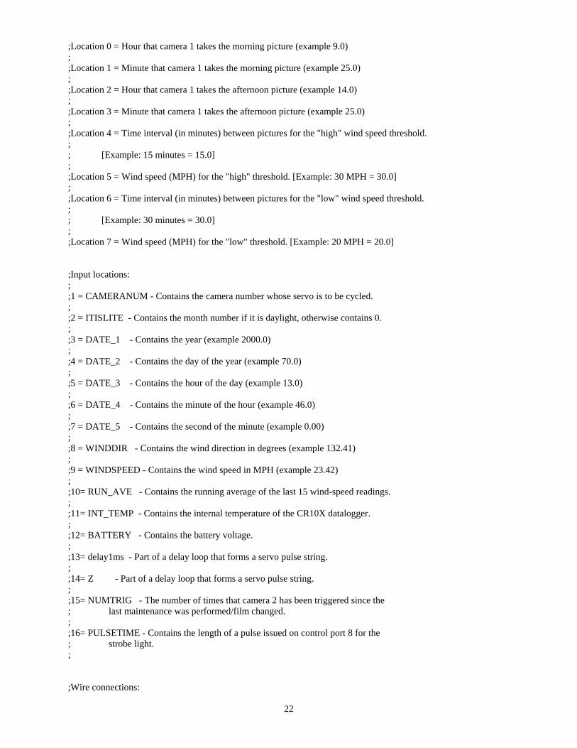
;Location 0 = Hour that camera 1 takes the morning picture (example 9.0) ; ;Location 1 = Minute that camera 1 takes the morning picture (example 25.0) ; ;Location 2 = Hour that camera 1 takes the afternoon picture (example 14.0) ; ;Location 3 = Minute that camera 1 takes the afternoon picture (example 25.0) ; ;Location 4 = Time interval (in minutes) between pictures for the "high" wind speed threshold. ; ; [Example: 15 minutes = 15.0]; ;Location 5 = Wind speed (MPH) for the "high" threshold. [Example: 30 MPH = 30.0]; ;Location 6 = Time interval (in minutes) between pictures for the "low" wind speed threshold. ; ; [Example: 30 minutes = 30.0]; ;Location 7 = Wind speed (MPH) for the "low" threshold. [Example: 20 MPH = 20.0]
;Input locations:; ;1 = CAMERANUM - Contains the camera number whose servo is to be cycled. ; ;2 = ITISLITE - Contains the month number if it is daylight, otherwise contains 0. ; ;3 = DATE_1 - Contains the year (example 2000.0) ; ;4 = DATE_2 - Contains the day of the year (example 70.0) ; ;5 = DATE_3 - Contains the hour of the day (example 13.0) ; ;6 = DATE_4 - Contains the minute of the hour (example 46.0) ; ;7 = DATE_5 - Contains the second of the minute (example 0.00) ; ;8 = WINDDIR - Contains the wind direction in degrees (example 132.41) ; ;9 = WINDSPEED - Contains the wind speed in MPH (example 23.42) ; ;10= RUN_AVE - Contains the running average of the last 15 wind-speed readings. ; ;11= INT_TEMP - Contains the internal temperature of the CR10X datalogger. ; ;12= BATTERY - Contains the battery voltage. ; ;13= delay1ms - Part of a delay loop that forms a servo pulse string. ; ;14= Z - Part of a delay loop that forms a servo pulse string. ; ;15= NUMTRIG - The number of times that camera 2 has been triggered since the ; last maintenance was performed/film changed. ; ;16= PULSETIME - Contains the length of a pulse issued on control port 8 for the ; strobe light. ;
;Wire connections:
22
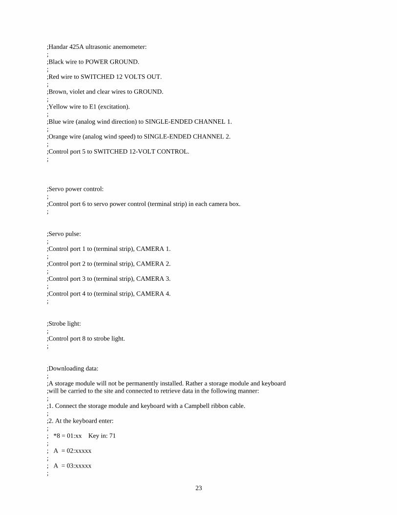
;Handar 425A ultrasonic anemometer:; ;Black wire to POWER GROUND. ; ;Red wire to SWITCHED 12 VOLTS OUT. ; ;Brown, violet and clear wires to GROUND. ; ;Yellow wire to E1 (excitation). ; ;Blue wire (analog wind direction) to SINGLE-ENDED CHANNEL 1. ; ;Orange wire (analog wind speed) to SINGLE-ENDED CHANNEL 2. ; ;Control port 5 to SWITCHED 12-VOLT CONTROL. ;
;Servo power control:; ;Control port 6 to servo power control (terminal strip) in each camera box. ;
;Servo pulse:; ;Control port 1 to (terminal strip), CAMERA 1. ; ;Control port 2 to (terminal strip), CAMERA 2. ; ;Control port 3 to (terminal strip), CAMERA 3. ; ;Control port 4 to (terminal strip), CAMERA 4. ;
;Strobe light: ; ;Control port 8 to strobe light. ;
;Downloading data:; ;A storage module will not be permanently installed. Rather a storage module and keyboard ;will be carried to the site and connected to retrieve data in the following manner: ; ;1. Connect the storage module and keyboard with a Campbell ribbon cable. ; ;2. At the keyboard enter: ; ; *8 = 01:xx Key in: 71 ; ; A = 02:xxxxx ; ; A = 03:xxxxx ;
23
; A = 04:00 ; ; 1A = 04:xx [xx will increment while dumping, will stop when dump is complete.] ;
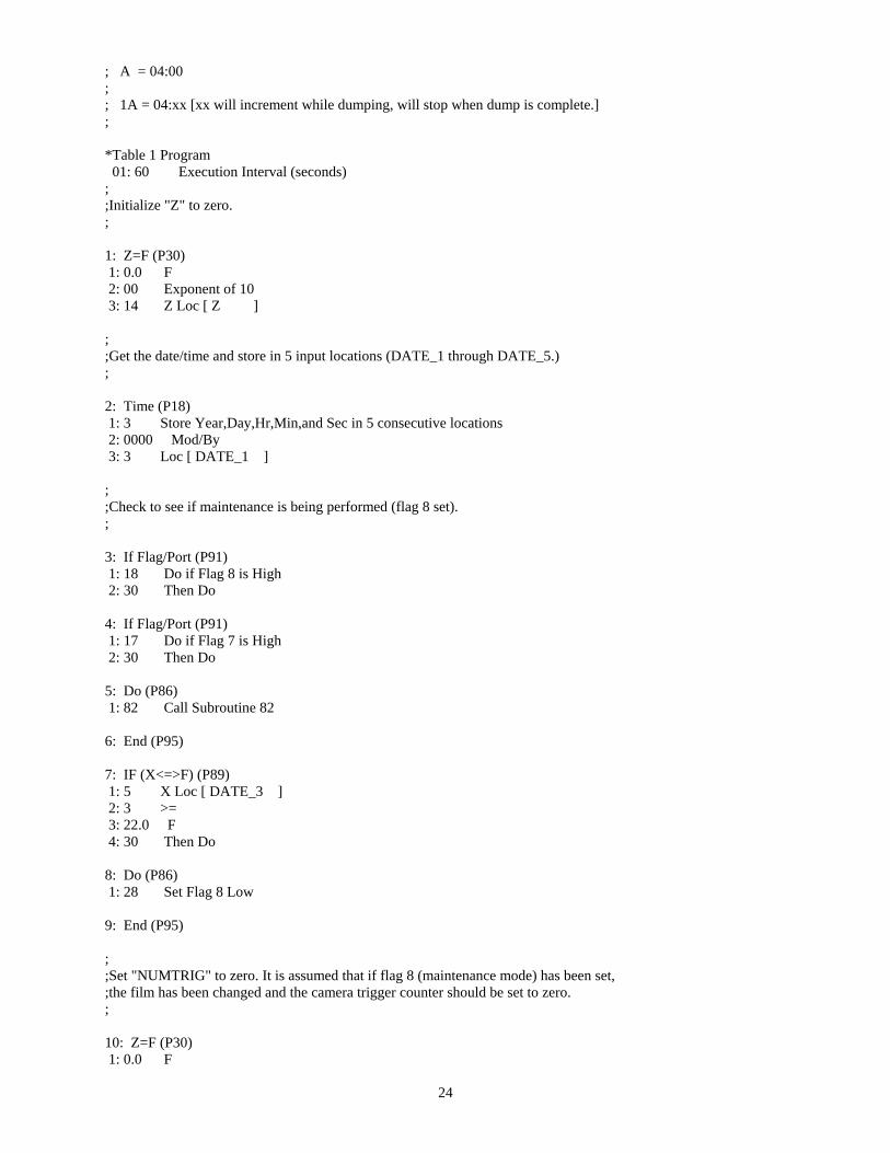
*Table 1 Program01: 60 Execution Interval (seconds)
; ;Initialize "Z" to zero. ;
1: Z=F (P30) 1: 0.0 F 2: 00 Exponent of 10 3: 14 Z Loc [ Z ]
; ;Get the date/time and store in 5 input locations (DATE_1 through DATE_5.) ;
2: Time (P18) 1: 3 Store Year,Day,Hr,Min,and Sec in 5 consecutive locations 2: 0000 Mod/By 3: 3 Loc [ DATE_1 ]
; ;Check to see if maintenance is being performed (flag 8 set). ;
3: If Flag/Port (P91) 1: 18 Do if Flag 8 is High 2: 30 Then Do
4: If Flag/Port (P91) 1: 17 Do if Flag 7 is High 2: 30 Then Do
5: Do (P86) 1: 82 Call Subroutine 82
6: End (P95)
7: IF (X<=>F) (P89) 1: 5 X Loc [ DATE_3 ] 2: 3 >= 3: 22.0 F 4: 30 Then Do
8: Do (P86) 1: 28 Set Flag 8 Low
9: End (P95)
; ;Set "NUMTRIG" to zero. It is assumed that if flag 8 (maintenance mode) has been set, ;the film has been changed and the camera trigger counter should be set to zero. ;
10: Z=F (P30) 1: 0.0 F
24
2: 00 Exponent of 10 3: 15 Z Loc [ NUMTRIG ]
11: Do (P86) 1: 0 Go to end of Program Table
12: End (P95)
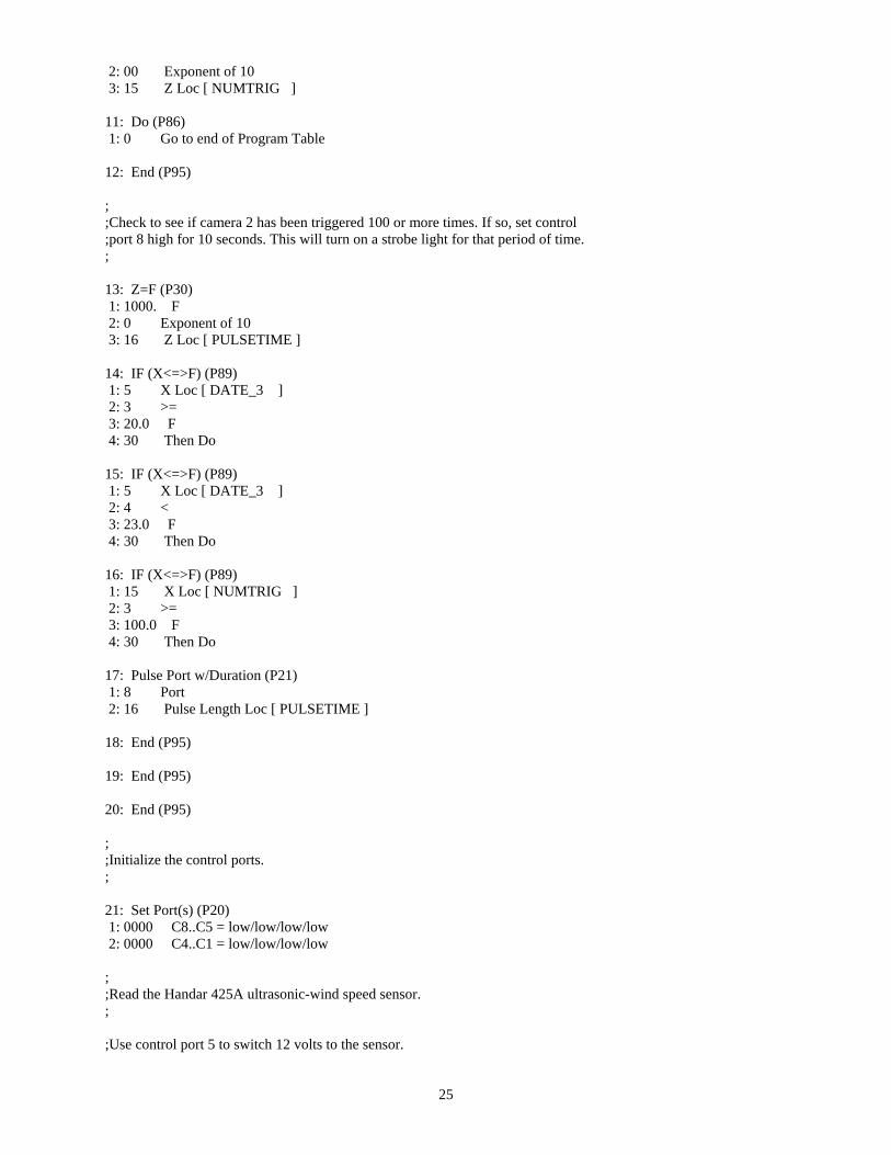
; ;Check to see if camera 2 has been triggered 100 or more times. If so, set control;port 8 high for 10 seconds. This will turn on a strobe light for that period of time. ;
13: Z=F (P30) 1: 1000. F 2: 0 Exponent of 10 3: 16 Z Loc [ PULSETIME ]
14: IF (X<=>F) (P89) 1: 5 X Loc [ DATE_3 ] 2: 3 >= 3: 20.0 F 4: 30 Then Do
15: IF (X<=>F) (P89) 1: 5 X Loc [ DATE_3 ] 2: 4 < 3: 23.0 F 4: 30 Then Do
16: IF (X<=>F) (P89) 1: 15 X Loc [ NUMTRIG ] 2: 3 >= 3: 100.0 F 4: 30 Then Do
17: Pulse Port w/Duration (P21) 1: 8 Port 2: 16 Pulse Length Loc [ PULSETIME ]
18: End (P95)
19: End (P95)
20: End (P95)
; ;Initialize the control ports. ;
21: Set Port(s) (P20) 1: 0000 C8..C5 = low/low/low/low 2: 0000 C4..C1 = low/low/low/low
; ;Read the Handar 425A ultrasonic-wind speed sensor. ;
;Use control port 5 to switch 12 volts to the sensor.
25
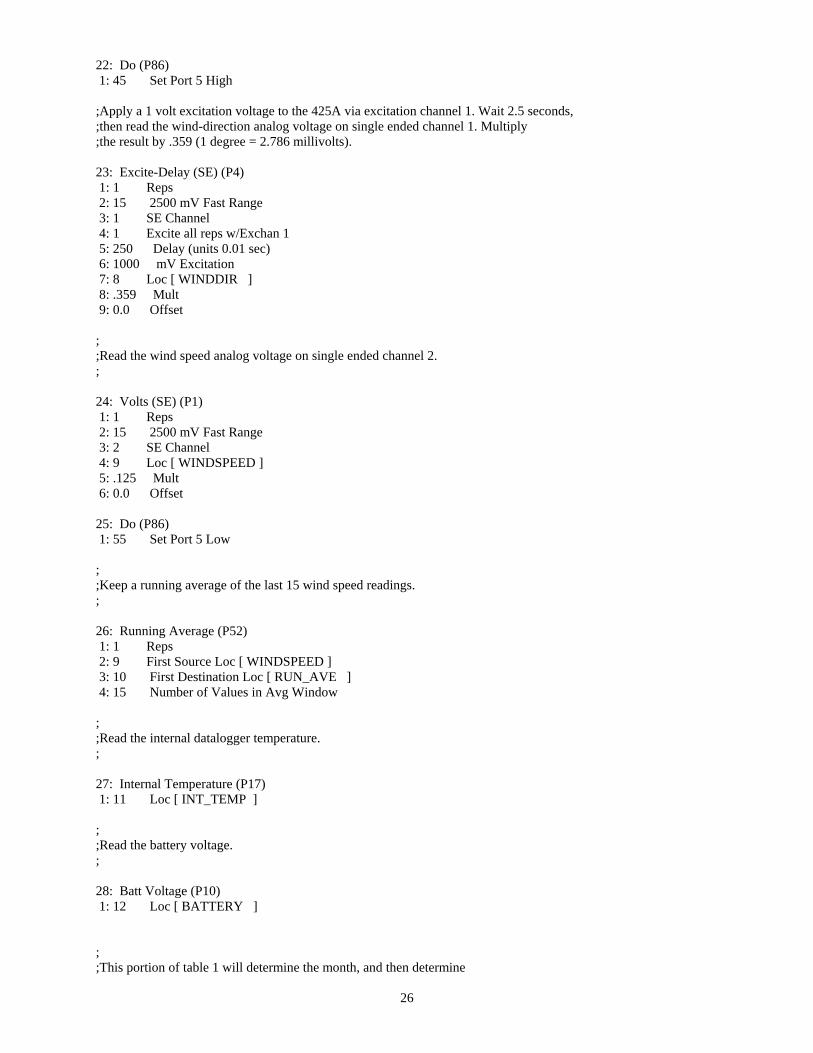
22: Do (P86) 1: 45 Set Port 5 High
;Apply a 1 volt excitation voltage to the 425A via excitation channel 1. Wait 2.5 seconds, ;then read the wind-direction analog voltage on single ended channel 1. Multiply ;the result by .359 (1 degree = 2.786 millivolts).
23: Excite-Delay (SE) (P4) 1: 1 Reps 2: 15 2500 mV Fast Range 3: 1 SE Channel 4: 1 Excite all reps w/Exchan 1 5: 250 Delay (units 0.01 sec) 6: 1000 mV Excitation 7: 8 Loc [ WINDDIR ] 8: .359 Mult 9: 0.0 Offset
; ;Read the wind speed analog voltage on single ended channel 2. ;
24: Volts (SE) (P1) 1: 1 Reps 2: 15 2500 mV Fast Range 3: 2 SE Channel 4: 9 Loc [ WINDSPEED ] 5: .125 Mult 6: 0.0 Offset
25: Do (P86) 1: 55 Set Port 5 Low
; ;Keep a running average of the last 15 wind speed readings. ;
26: Running Average (P52) 1: 1 Reps 2: 9 First Source Loc [ WINDSPEED ] 3: 10 First Destination Loc [ RUN_AVE ] 4: 15 Number of Values in Avg Window
; ;Read the internal datalogger temperature. ;
27: Internal Temperature (P17) 1: 11 Loc [ INT_TEMP ]
; ;Read the battery voltage. ;
28: Batt Voltage (P10) 1: 12 Loc [ BATTERY ]
; ;This portion of table 1 will determine the month, and then determine
26
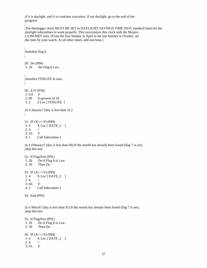
;if it is daylight, and if so continue execution. If not daylight, go to the end of the ;program. ; ;The datalogger clock MUST BE SET to DAYLIGHT SAVINGS TIME (NOT standard time) for the ;daylight subroutines to work properly. This syncronizes this clock with the Mojave ;CLIM-MET sites. [From the first Sunday in April to the last Sunday in October, set;the time by your watch. At all other times, add one hour.]
; ;Initialize flag 6.;
29: Do (P86) 1: 26 Set Flag 6 Low
; ;Initialize ITISLITE to zero.;
30: Z=F (P30) 1: 0.0 F 2: 00 Exponent of 10 3: 2 Z Loc [ ITISLITE ]
;Is it January? (day is less than 32.) ;
31: IF (X<=>F) (P89) 1: 4 X Loc [ DATE_2 ] 2: 4 < 3: 32. F 4: 1 Call Subroutine 1
;Is it February? (day is less than 60) If the month has already been found (flag 7 is set), ;skip this test.
32: If Flag/Port (P91) 1: 26 Do if Flag 6 is Low 2: 30 Then Do
33: IF (X<=>F) (P89) 1: 4 X Loc [ DATE_2 ] 2: 4 < 3: 60. F 4: 2 Call Subroutine 2
34: End (P95)
;Is it March? (day is less than 91) If the month has already been found (flag 7 is set), ;skip this test.
35: If Flag/Port (P91) 1: 26 Do if Flag 6 is Low 2: 30 Then Do
36: IF (X<=>F) (P89) 1: 4 X Loc [ DATE_2 ] 2: 4 < 3: 91. F
27
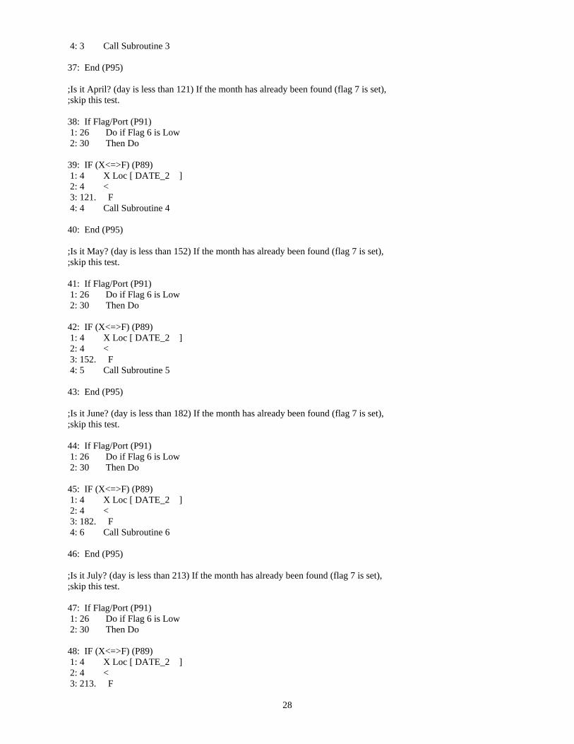
4: 3 Call Subroutine 3
37: End (P95)
;Is it April? (day is less than 121) If the month has already been found (flag 7 is set), ;skip this test.
38: If Flag/Port (P91) 1: 26 Do if Flag 6 is Low 2: 30 Then Do
39: IF (X<=>F) (P89) 1: 4 X Loc [ DATE_2 ] 2: 4 < 3: 121. F 4: 4 Call Subroutine 4
40: End (P95)
;Is it May? (day is less than 152) If the month has already been found (flag 7 is set), ;skip this test.
41: If Flag/Port (P91) 1: 26 Do if Flag 6 is Low 2: 30 Then Do
42: IF (X<=>F) (P89) 1: 4 X Loc [ DATE_2 ] 2: 4 < 3: 152. F 4: 5 Call Subroutine 5
43: End (P95)
;Is it June? (day is less than 182) If the month has already been found (flag 7 is set), ;skip this test.
44: If Flag/Port (P91) 1: 26 Do if Flag 6 is Low 2: 30 Then Do
45: IF (X<=>F) (P89) 1: 4 X Loc [ DATE_2 ] 2: 4 < 3: 182. F 4: 6 Call Subroutine 6
46: End (P95)
;Is it July? (day is less than 213) If the month has already been found (flag 7 is set), ;skip this test.
47: If Flag/Port (P91) 1: 26 Do if Flag 6 is Low 2: 30 Then Do
48: IF (X<=>F) (P89) 1: 4 X Loc [ DATE_2 ] 2: 4 < 3: 213. F
28
4: 7 Call Subroutine 7
49: End (P95)
;Is it August? (day is less than 244) If the month has already been found (flag 7 is set), ;skip this test.
50: If Flag/Port (P91) 1: 26 Do if Flag 6 is Low 2: 30 Then Do
51: IF (X<=>F) (P89) 1: 4 X Loc [ DATE_2 ] 2: 4 < 3: 244. F 4: 8 Call Subroutine 8
52: End (P95)
;Is it September? (day is less than 274) If the month has already been found (flag 7 is set), ;skip this test.
53: If Flag/Port (P91) 1: 26 Do if Flag 6 is Low 2: 30 Then Do
54: IF (X<=>F) (P89) 1: 4 X Loc [ DATE_2 ] 2: 4 < 3: 274. F 4: 9 Call Subroutine 9
55: End (P95)
;Is it October? (day is less than 305) If the month has already been found (flag 7 is set), ;skip this test.
56: If Flag/Port (P91) 1: 26 Do if Flag 6 is Low 2: 30 Then Do
57: IF (X<=>F) (P89) 1: 4 X Loc [ DATE_2 ] 2: 4 < 3: 305. F 4: 79 Call Subroutine 79
58: End (P95)
;Is it November? (day is less than 335) If the month has already been found (flag 7 is set), ;skip this test.
59: If Flag/Port (P91) 1: 26 Do if Flag 6 is Low 2: 30 Then Do
60: IF (X<=>F) (P89) 1: 4 X Loc [ DATE_2 ] 2: 4 < 3: 335. F
29
4: 80 Call Subroutine 80
61: End (P95)
;Is it December? (day is less than 367) If the month has already been found (flag 7 is set), ;skip this test.
62: If Flag/Port (P91) 1: 26 Do if Flag 6 is Low 2: 30 Then Do
63: IF (X<=>F) (P89) 1: 4 X Loc [ DATE_2 ] 2: 4 < 3: 367. F 4: 81 Call Subroutine 81
64: End (P95)
;The following instruction(s) are executed if the month is found and the time of day is within ;daylight limits.
65: If time is (P92) 1: 0 Minutes (Seconds --) into a 2: 120 Interval (same units as above) 3: 10 Set Output Flag High (Flag 0)
; ;Set Array ID to "505" (Site = 50, data ID = 3) ;
66: Set Active Storage Area (P80) 1: 01 Final Storage Area 1 2: 505 Array ID
; ;Save real time, wind vector, internal temperature and battery voltage data. ;
67: Real Time (P77) 1: 1120 (Same as 1220) Y,D,Hr/Mn
68: Wind Vector (P69) 1: 1 Reps 2: 25 Samples per Sub-Interval 3: 01 S, é1 Polar 4: 9 Wind Speed/East Loc [ WINDSPEED ] 5: 8 Wind Direction/North Loc [ WINDDIR
69: Average (P71) 1: 1 Reps 2: 11 Loc [ INT_TEMP ]
70: Minimize (P74) 1: 1 Reps 2: 00 Time Option 3: 12 Loc [ BATTERY ]
71: Maximize (P73) 1: 1 Reps
]
30
2: 00 Time Option 3: 12 Loc [ BATTERY ]
; ;Take a picture with camera #1? (Morning and evening camera.) ;
; ;If the time of day is 09:25 take a picture with camera #1 (always make time 5-minutes ;earlier than the 30-minute interval.) ;
72: IF (X<=>F) (P89) 1: 5 X Loc [ DATE_3 ] 2: 1 = 3: 9.0 F @@0 4: 30 Then Do
73: IF (X<=>F) (P89) 1: 6 X Loc [ DATE_4 ] 2: 1 = 3: 25.0 F @@1 4: 30 Then Do
; ;Set flag 0 high to prevent being interrupted. ;
74: Do (P86) 1: 10 Set Output Flag High (Flag 0)
;Initialize control ports 1 - 8 to the off or low output.
75: Set Port(s) (P20) 1: 0000 C8..C5 = low/low/low/low 2: 0000 C4,C3,C2,C1 Options
; ;Turn power on to the servos via control port 6. ;
76: Do (P86) 1: 46 Set Port 6 High
;Move the servo to the "power on" position. Issue 1.16 millisecond width pulses.
77: Beginning of Loop (P87) 1: 0 Delay 2: 30 Loop Count
78: Do (P86) 1: 61 Toggle Port 1
;Delay 1.16 milliseconds (perfect!!)
79: Do (P86) 1: 10 Set Output Flag High (Flag 0)
80: Do (P86)
31

1: 10 Set Output Flag High (Flag 0)
81: If Flag/Port (P91) 1: 20 Do if Output Flag is Low (Flag 0) 2: 10 Set Output Flag High (Flag 0)
82: Do (P86) 1: 61 Toggle Port 1
;Delay 20 milliseconds
83: Beginning of Loop (P87) 1: 0 Delay 2: 12 Loop Count
84: Z=F (P30) 1: 126. F 2: 1 Exponent of 10 3: 13 Z Loc [ delay1ms ]
85: End (P95)
86: End (P95)
;Issue a pulse train (on control port 1) with 1.84 millisecond pulse width. Pulses are spaced ;20 milliseconds apart (leading edge to leading edge - 50 hertz). Pulses are positive going. ;This pulse train will put the servo at the "home" position.
87: Beginning of Loop (P87) 1: 0 Delay 2: 30 Loop Count
88: Do (P86) 1: 61 Toggle Port 1
;Delay 1.84 milliseconds [perfect!]
89: Z=Z+1 (P32) 1: 14 Z Loc [ Z ]
90: Z=Z+1 (P32) 1: 14 Z Loc [ Z ]
91: Do (P86) 1: 61 Toggle Port 1
;Delay 20 milliseconds
92: Beginning of Loop (P87) 1: 0 Delay 2: 12 Loop Count
93: Z=F (P30) 1: 126. F 2: 1 Exponent of 10 3: 13 Z Loc [ delay1ms ]
94: End (P95)
95: End (P95)
32
96: Do (P86) 1: 56 Set Port 6 Low
97: Do (P86) 1: 10 Set Output Flag High (Flag 0)
98: Set Active Storage Area (P80) 1: 01 Final Storage Area 1 2: 501 Array ID
99: Real Time (P77) 1: 1121 (Same as 1221) Y,D,Hr/Mn,Sec
100: Sample (P70) 1: 1 Reps 2: 10 Loc [ RUN_AVE ]
101: Do (P86) 1: 0 Go to end of Program Table
102: End (P95)
103: End (P95)
; ;If the time of day is 14:25 take a picture with camera #1 (always make time 5-minutes ;earlier than the 30-minute interval.) ;
104: IF (X<=>F) (P89) 1: 5 X Loc [ DATE_3 ] 2: 1 = 3: 14.0 F @@2 4: 30 Then Do
105: IF (X<=>F) (P89) 1: 6 X Loc [ DATE_4 ] 2: 1 = 3: 25.0 F @@3 4: 30 Then Do
; ;Set flag 0 high to prevent being interrupted. ;
106: Do (P86) 1: 10 Set Output Flag High (Flag 0)
;Initialize control ports 1 - 8 to the off or low output.
107: Set Port(s) (P20) 1: 0000 C8..C5 = low/low/low/low 2: 0000 C4,C3,C2,C1 Options
; ;Turn power on to the servos via control port 6. ;
33
108: Do (P86) 1: 46 Set Port 6 High
;Move the servo to the "power on" position. Issue 1.16 millisecond width pulses.
109: Beginning of Loop (P87) 1: 0 Delay 2: 30 Loop Count
110: Do (P86) 1: 61 Toggle Port 1
;Delay 1.16 milliseconds (perfect!!)
111: Do (P86) 1: 10 Set Output Flag High (Flag 0)
112: Do (P86) 1: 10 Set Output Flag High (Flag 0)
113: If Flag/Port (P91) 1: 20 Do if Output Flag is Low (Flag 0) 2: 10 Set Output Flag High (Flag 0)
114: Do (P86) 1: 61 Toggle Port 1
;Delay 20 milliseconds
115: Beginning of Loop (P87) 1: 0 Delay 2: 12 Loop Count
116: Z=F (P30) 1: 126. F 2: 1 Exponent of 10 3: 13 Z Loc [ delay1ms ]
117: End (P95)
118: End (P95)
;Issue a pulse train (on control port 1) with 1.84 millisecond pulse width. Pulses are spaced ;20 milliseconds apart (leading edge to leading edge - 50 hertz). Pulses are positive going. ;This pulse train will put the servo at the "home" position.
119: Beginning of Loop (P87) 1: 0 Delay 2: 30 Loop Count
120: Do (P86) 1: 61 Toggle Port 1
;Delay 1.84 milliseconds [perfect!]
121: Z=Z+1 (P32) 1: 14 Z Loc [ Z ]
122: Z=Z+1 (P32) 1: 14 Z Loc [ Z ]
34

123: Do (P86) 1: 61 Toggle Port 1
;Delay 20 milliseconds
124: Beginning of Loop (P87) 1: 0 Delay 2: 12 Loop Count
125: Z=F (P30) 1: 126. F 2: 1 Exponent of 10 3: 13 Z Loc [ delay1ms ]
126: End (P95)
127: End (P95)
128: Do (P86) 1: 56 Set Port 6 Low
129: Do (P86) 1: 10 Set Output Flag High (Flag 0)
130: Set Active Storage Area (P80) 1: 01 Final Storage Area 1 2: 501 Array ID
131: Real Time (P77) 1: 1121 (Same as 1221) Y,D,Hr/Mn,Sec
132: Sample (P70) 1: 1 Reps 2: 10 Loc [ RUN_AVE ]
133: Do (P86) 1: 0 Go to end of Program Table
134: End (P95)
135: End (P95)
; ;Take a 15-minute-interval picture? (Wind speed => 35 MPH) ;
136: If time is (P92) 1: 0 Minutes (Seconds --) into a 2: 15 Interval (same units as above) @@4 3: 30 Then Do
137: IF (X<=>F) (P89) 1: 10 X Loc [ RUN_AVE ] 2: 3 >= 3: 35.0 F @@5 4: 30 Then Do
138: Do (P86)
35

1: 12 Set Flag 2 High
; ;Set flag 0 high to prevent being interrupted. ;
139: Do (P86) 1: 10 Set Output Flag High (Flag 0)
;Initialize control ports 1 - 8 to the off or low output.
140: Set Port(s) (P20) 1: 0000 C8..C5 = low/low/low/low 2: 0000 C4,C3,C2,C1 Options
; ;Turn power on to the servos via control port 6. ;
141: Do (P86) 1: 46 Set Port 6 High
;Move the servo to the "power on" position. Issue 1.16 millisecond width pulses.
142: Beginning of Loop (P87) 1: 0 Delay 2: 30 Loop Count
143: Do (P86) 1: 62 Toggle Port 2
;Delay 1.16 milliseconds (perfect!!)
144: Do (P86) 1: 10 Set Output Flag High (Flag 0)
145: Do (P86) 1: 10 Set Output Flag High (Flag 0)
146: If Flag/Port (P91) 1: 20 Do if Output Flag is Low (Flag 0) 2: 10 Set Output Flag High (Flag 0)
147: Do (P86) 1: 62 Toggle Port 2
;Delay 20 milliseconds
148: Beginning of Loop (P87) 1: 0 Delay 2: 12 Loop Count
149: Z=F (P30) 1: 126. F 2: 1 Exponent of 10 3: 13 Z Loc [ delay1ms ]
150: End (P95)
151: End (P95)
36
;Issue a pulse train (on control port 1) with 1.84 millisecond pulse width. Pulses are spaced ;20 milliseconds apart (leading edge to leading edge - 50 hertz). Pulses are positive going. ;This pulse train will put the servo at the "home" position.
152: Beginning of Loop (P87) 1: 0 Delay 2: 30 Loop Count
153: Do (P86) 1: 62 Toggle Port 2
;Delay 1.84 milliseconds [perfect!]
154: Z=Z+1 (P32) 1: 14 Z Loc [ Z ]
155: Z=Z+1 (P32) 1: 14 Z Loc [ Z ]
156: Do (P86) 1: 62 Toggle Port 2
;Delay 20 milliseconds
157: Beginning of Loop (P87) 1: 0 Delay 2: 12 Loop Count
158: Z=F (P30) 1: 126. F 2: 1 Exponent of 10 3: 13 Z Loc [ delay1ms ]
159: End (P95)
160: End (P95)
161: Do (P86) 1: 56 Set Port 6 Low
162: Do (P86) 1: 10 Set Output Flag High (Flag 0)
163: Set Active Storage Area (P80) 1: 01 Final Storage Area 1 2: 502 Array ID
164: Real Time (P77) 1: 1121 (Same as 1221) Y,D,Hr/Mn,Sec
165: Sample (P70) 1: 1 Reps 2: 10 Loc [ RUN_AVE ]
; ;Update the trigger counter ;
166: Z=Z+1 (P32)
37
1: 15 Z Loc [ NUMTRIG ]
167: Do (P86) 1: 0 Go to end of Program Table
168: End (P95)
169: End (P95)
; ;Take a picture with camera #3 if flag 2 is set. ;
170: If Flag/Port (P91) 1: 12 Do if Flag 2 is High 2: 30 Then Do
171: Do (P86) 1: 22 Set Flag 2 Low
172: Do (P86) 1: 13 Set Flag 3 High
; ;Set flag 0 high to prevent being interrupted. ;
173: Do (P86) 1: 10 Set Output Flag High (Flag 0)
;Initialize control ports 1 - 8 to the off or low output.
174: Set Port(s) (P20) 1: 0000 C8..C5 = low/low/low/low 2: 0000 C4,C3,C2,C1 Options
; ;Turn power on to the servos via control port 6. ;
175: Do (P86) 1: 46 Set Port 6 High
;Move the servo to the "power on" position. Issue 1.16 millisecond width pulses.
176: Beginning of Loop (P87) 1: 0 Delay 2: 30 Loop Count
177: Do (P86) 1: 63 Toggle Port 3
;Delay 1.16 milliseconds (perfect!!)
178: Do (P86) 1: 10 Set Output Flag High (Flag 0)
179: Do (P86) 1: 10 Set Output Flag High (Flag 0)
38
180: If Flag/Port (P91) 1: 20 Do if Output Flag is Low (Flag 0) 2: 10 Set Output Flag High (Flag 0)
181: Do (P86) 1: 63 Toggle Port 3
;Delay 20 milliseconds
182: Beginning of Loop (P87) 1: 0 Delay 2: 12 Loop Count
183: Z=F (P30) 1: 126. F 2: 1 Exponent of 10 3: 13 Z Loc [ delay1ms ]
184: End (P95)
185: End (P95)
;Issue a pulse train (on control port 1) with 1.84 millisecond pulse width. Pulses are spaced ;20 milliseconds apart (leading edge to leading edge - 50 hertz). Pulses are positive going. ;This pulse train will put the servo at the "home" position.
186: Beginning of Loop (P87) 1: 0 Delay 2: 30 Loop Count
187: Do (P86) 1: 63 Toggle Port 3
;Delay 1.84 milliseconds [perfect!]
188: Z=Z+1 (P32) 1: 14 Z Loc [ Z ]
189: Z=Z+1 (P32) 1: 14 Z Loc [ Z ]
190: Do (P86) 1: 63 Toggle Port 3
;Delay 20 milliseconds
191: Beginning of Loop (P87) 1: 0 Delay 2: 12 Loop Count
192: Z=F (P30) 1: 126. F 2: 1 Exponent of 10 3: 13 Z Loc [ delay1ms ]
193: End (P95)
194: End (P95)
39
195: Do (P86) 1: 56 Set Port 6 Low
196: Do (P86) 1: 10 Set Output Flag High (Flag 0)
197: Set Active Storage Area (P80) 1: 01 Final Storage Area 1 2: 503 Array ID
198: Real Time (P77) 1: 1121 (Same as 1221) Y,D,Hr/Mn,Sec
199: Do (P86) 1: 0 Go to end of Program Table
200: End (P95)
; ;Take a picture with camera #4 if flag 3 is set. ;
201: If Flag/Port (P91) 1: 13 Do if Flag 3 is High 2: 30 Then Do
202: Do (P86) 1: 23 Set Flag 3 Low
; ;Set flag 0 high to prevent being interrupted. ;
203: Do (P86) 1: 10 Set Output Flag High (Flag 0)
;Initialize control ports 1 - 8 to the off or low output.
204: Set Port(s) (P20) 1: 0000 C8..C5 = low/low/low/low 2: 0000 C4,C3,C2,C1 Options
; ;Turn power on to the servos via control port 6. ;
205: Do (P86) 1: 46 Set Port 6 High
;Move the servo to the "power on" position. Issue 1.16 millisecond width pulses.
206: Beginning of Loop (P87) 1: 0 Delay 2: 30 Loop Count
207: Do (P86) 1: 64 Toggle Port 4
;Delay 1.16 milliseconds (perfect!!)
40
208: Do (P86) 1: 10 Set Output Flag High (Flag 0)
209: Do (P86) 1: 10 Set Output Flag High (Flag 0)
210: If Flag/Port (P91) 1: 20 Do if Output Flag is Low (Flag 0) 2: 10 Set Output Flag High (Flag 0)
211: Do (P86) 1: 64 Toggle Port 4
;Delay 20 milliseconds
212: Beginning of Loop (P87) 1: 0 Delay 2: 12 Loop Count
213: Z=F (P30) 1: 126. F 2: 1 Exponent of 10 3: 13 Z Loc [ delay1ms ]
214: End (P95)
215: End (P95)
;Issue a pulse train (on control port 1) with 1.84 millisecond pulse width. Pulses are spaced ;20 milliseconds apart (leading edge to leading edge - 50 hertz). Pulses are positive going. ;This pulse train will put the servo at the "home" position.
216: Beginning of Loop (P87) 1: 0 Delay 2: 30 Loop Count
217: Do (P86) 1: 64 Toggle Port 4
;Delay 1.84 milliseconds [perfect!]
218: Z=Z+1 (P32) 1: 14 Z Loc [ Z ]
219: Z=Z+1 (P32) 1: 14 Z Loc [ Z ]
220: Do (P86) 1: 64 Toggle Port 4
;Delay 20 milliseconds
221: Beginning of Loop (P87) 1: 0 Delay 2: 12 Loop Count
222: Z=F (P30) 1: 126. F 2: 1 Exponent of 10 3: 13 Z Loc [ delay1ms ]
41
223: End (P95)
224: End (P95)
225: Do (P86) 1: 56 Set Port 6 Low
226: Do (P86) 1: 10 Set Output Flag High (Flag 0)
227: Set Active Storage Area (P80) 1: 01 Final Storage Area 1 2: 504 Array ID
228: Real Time (P77) 1: 1121 (Same as 1221) Y,D,Hr/Mn,Sec
229: Do (P86) 1: 0 Go to end of Program Table
230: End (P95)
; ;Take a 30-minute interval picture? (Wind speed => 25 MPH) ;
231: If time is (P92) 1: 0 Minutes (Seconds --) into a 2: 30 Interval (same units as above) @@6 3: 30 Then Do
232: IF (X<=>F) (P89) 1: 10 X Loc [ RUN_AVE ] 2: 3 >= 3: 25.0 F @@7 4: 30 Then Do
233: Do (P86) 1: 12 Set Flag 2 High
; ;Set flag 0 high to prevent being interrupted. ;
234: Do (P86) 1: 10 Set Output Flag High (Flag 0)
;Initialize control ports 1 - 8 to the off or low output.
235: Set Port(s) (P20) 1: 0000 C8..C5 = low/low/low/low 2: 0000 C4,C3,C2,C1 Options
; ;Turn power on to the servos via control port 6. ;
236: Do (P86) 1: 46 Set Port 6 High
42
;Move the servo to the "power on" position. Issue 1.16 millisecond width pulses.
237: Beginning of Loop (P87) 1: 0 Delay 2: 30 Loop Count
238: Do (P86) 1: 62 Toggle Port 2
;Delay 1.16 milliseconds (perfect!!)
239: Do (P86) 1: 10 Set Output Flag High (Flag 0)
240: Do (P86) 1: 10 Set Output Flag High (Flag 0)
241: If Flag/Port (P91) 1: 20 Do if Output Flag is Low (Flag 0) 2: 10 Set Output Flag High (Flag 0)
242: Do (P86) 1: 62 Toggle Port 2
;Delay 20 milliseconds
243: Beginning of Loop (P87) 1: 0 Delay 2: 12 Loop Count
244: Z=F (P30) 1: 126. F 2: 1 Exponent of 10 3: 13 Z Loc [ delay1ms ]
245: End (P95)
246: End (P95)
;Issue a pulse train (on control port 1) with 1.84 millisecond pulse width. Pulses are spaced ;20 milliseconds apart (leading edge to leading edge - 50 hertz). Pulses are positive going. ;This pulse train will put the servo at the "home" position.
247: Beginning of Loop (P87) 1: 0 Delay 2: 30 Loop Count
248: Do (P86) 1: 62 Toggle Port 2
;Delay 1.84 milliseconds [perfect!]
249: Z=Z+1 (P32) 1: 14 Z Loc [ Z ]
250: Z=Z+1 (P32) 1: 14 Z Loc [ Z ]
251: Do (P86)
43
1: 62 Toggle Port 2
;Delay 20 milliseconds
252: Beginning of Loop (P87) 1: 0 Delay 2: 12 Loop Count
253: Z=F (P30) 1: 126. F 2: 1 Exponent of 10 3: 13 Z Loc [ delay1ms ]
254: End (P95)
255: End (P95)
256: Do (P86) 1: 56 Set Port 6 Low
257: Do (P86) 1: 10 Set Output Flag High (Flag 0)
258: Set Active Storage Area (P80) 1: 01 Final Storage Area 1 2: 502 Array ID
259: Real Time (P77) 1: 1121 (Same as 1221) Y,D,Hr/Mn,Sec
260: Sample (P70) 1: 1 Reps 2: 10 Loc [ RUN_AVE ]
261: Do (P86) 1: 0 Go to end of Program Table
262: End (P95)
263: End (P95)
; ;Take a picture with camera #3 if flag 2 is set. ;
264: If Flag/Port (P91) 1: 12 Do if Flag 2 is High 2: 30 Then Do
265: Do (P86) 1: 22 Set Flag 2 Low
266: Do (P86) 1: 13 Set Flag 3 High
; ;Set flag 0 high to prevent being interrupted. ;
44
267: Do (P86) 1: 10 Set Output Flag High (Flag 0)
;Initialize control ports 1 - 8 to the off or low output.
268: Set Port(s) (P20) 1: 0000 C8..C5 = low/low/low/low 2: 0000 C4,C3,C2,C1 Options
; ;Turn power on to the servos via control port 6. ;
269: Do (P86) 1: 46 Set Port 6 High
;Move the servo to the "power on" position. Issue 1.16 millisecond width pulses.
270: Beginning of Loop (P87) 1: 0 Delay 2: 30 Loop Count
271: Do (P86) 1: 63 Toggle Port 3
;Delay 1.16 milliseconds (perfect!!)
272: Do (P86) 1: 10 Set Output Flag High (Flag 0)
273: Do (P86) 1: 10 Set Output Flag High (Flag 0)
274: If Flag/Port (P91) 1: 20 Do if Output Flag is Low (Flag 0) 2: 10 Set Output Flag High (Flag 0)
275: Do (P86) 1: 63 Toggle Port 3
;Delay 20 milliseconds
276: Beginning of Loop (P87) 1: 0 Delay 2: 12 Loop Count
277: Z=F (P30) 1: 126. F 2: 1 Exponent of 10 3: 13 Z Loc [ delay1ms ]
278: End (P95)
279: End (P95)
;Issue a pulse train (on control port 1) with 1.84 millisecond pulse width. Pulses are spaced ;20 milliseconds apart (leading edge to leading edge - 50 hertz). Pulses are positive going. ;This pulse train will put the servo at the "home" position.
45
280: Beginning of Loop (P87) 1: 0 Delay 2: 30 Loop Count
281: Do (P86) 1: 63 Toggle Port 3
;Delay 1.84 milliseconds [perfect!]
282: Z=Z+1 (P32) 1: 14 Z Loc [ Z ]
283: Z=Z+1 (P32) 1: 14 Z Loc [ Z ]
284: Do (P86) 1: 63 Toggle Port 3
;Delay 20 milliseconds
285: Beginning of Loop (P87) 1: 0 Delay 2: 12 Loop Count
286: Z=F (P30) 1: 126. F 2: 1 Exponent of 10 3: 13 Z Loc [ delay1ms ]
287: End (P95)
288: End (P95)
289: Do (P86) 1: 56 Set Port 6 Low
290: Do (P86) 1: 10 Set Output Flag High (Flag 0)
291: Set Active Storage Area (P80) 1: 01 Final Storage Area 1 2: 503 Array ID
292: Real Time (P77) 1: 1121 (Same as 1221) Y,D,Hr/Mn,Sec
293: Do (P86) 1: 0 Go to end of Program Table
294: End (P95)
; ;Take a picture with camera #4 if flag 3 is set. ;
295: If Flag/Port (P91) 1: 13 Do if Flag 3 is High 2: 30 Then Do
296: Do (P86)
46
1: 23 Set Flag 3 Low
; ;Set flag 0 high to prevent being interrupted. ;
297: Do (P86) 1: 10 Set Output Flag High (Flag 0)
;Initialize control ports 1 - 8 to the off or low output.
298: Set Port(s) (P20) 1: 0000 C8..C5 = low/low/low/low 2: 0000 C4,C3,C2,C1 Options
; ;Turn power on to the servos via control port 6. ;
299: Do (P86) 1: 46 Set Port 6 High
;Move the servo to the "power on" position. Issue 1.16 millisecond width pulses.
300: Beginning of Loop (P87) 1: 0 Delay 2: 30 Loop Count
301: Do (P86) 1: 64 Toggle Port 4
;Delay 1.16 milliseconds (perfect!!)
302: Do (P86) 1: 10 Set Output Flag High (Flag 0)
303: Do (P86) 1: 10 Set Output Flag High (Flag 0)
304: If Flag/Port (P91) 1: 20 Do if Output Flag is Low (Flag 0) 2: 10 Set Output Flag High (Flag 0)
305: Do (P86) 1: 64 Toggle Port 4
;Delay 20 milliseconds
306: Beginning of Loop (P87) 1: 0 Delay 2: 12 Loop Count
307: Z=F (P30) 1: 126. F 2: 1 Exponent of 10 3: 13 Z Loc [ delay1ms ]
308: End (P95)
309: End (P95)
47
;Issue a pulse train (on control port 1) with 1.84 millisecond pulse width. Pulses are spaced ;20 milliseconds apart (leading edge to leading edge - 50 hertz). Pulses are positive going. ;This pulse train will put the servo at the "home" position.
310: Beginning of Loop (P87) 1: 0 Delay 2: 30 Loop Count
311: Do (P86) 1: 64 Toggle Port 4
;Delay 1.84 milliseconds [perfect!]
312: Z=Z+1 (P32) 1: 14 Z Loc [ Z ]
313: Z=Z+1 (P32) 1: 14 Z Loc [ Z ]
314: Do (P86) 1: 64 Toggle Port 4
;Delay 20 milliseconds
315: Beginning of Loop (P87) 1: 0 Delay 2: 12 Loop Count
316: Z=F (P30) 1: 126. F 2: 1 Exponent of 10 3: 13 Z Loc [ delay1ms ]
317: End (P95)
318: End (P95)
319: Do (P86) 1: 56 Set Port 6 Low
320: Do (P86) 1: 10 Set Output Flag High (Flag 0)
321: Set Active Storage Area (P80) 1: 01 Final Storage Area 1 2: 504 Array ID
322: Real Time (P77) 1: 1121 (Same as 1221) Y,D,Hr/Mn,Sec
323: Do (P86) 1: 0 Go to end of Program Table
324: End (P95)
*Table 2 Program 02: 0000 Execution Interval (seconds)
48

*Table 3 Subroutines
1: Beginning of Subroutine (P85) 1: 1 Subroutine 1
;January's earliest sunrise = 06:45 standard time, 07:45 DST ; latest sunset = 17:21 standard time, 18:21 DST
2: IF (X<=>F) (P89) 1: 5 X Loc [ DATE_3 ] 2: 4 < 3: 8. F 4: 0 Go to end of Program Table
3: IF (X<=>F) (P89) 1: 5 X Loc [ DATE_3 ] 2: 3 >= 3: 18. F 4: 0 Go to end of Program Table
4: Do (P86) 1: 16 Set Flag 6 High
5: Z=F (P30) 1: 1. F 2: 00 Exponent of 10 3: 2 Z Loc [ ITISLITE ]
6: End (P95)
7: Beginning of Subroutine (P85) 1: 2 Subroutine 2
;February's earliset sunrise = 06:19 standard time, 07:19 DST ; latest sunset = 17:46 standard time, 18:46 DST
8: IF (X<=>F) (P89) 1: 5 X Loc [ DATE_3 ] 2: 4 < 3: 7. F 4: 0 Go to end of Program Table
9: IF (X<=>F) (P89) 1: 5 X Loc [ DATE_3 ] 2: 3 >= 3: 19. F 4: 0 Go to end of Program Table
10: Do (P86) 1: 16 Set Flag 6 High
11: Z=F (P30) 1: 2. F 2: 00 Exponent of 10 3: 2 Z Loc [ ITISLITE ]
12: End (P95)
13: Beginning of Subroutine (P85) 1: 3 Subroutine 3
49

;March's earliest sunrise = 05:38 standard time, 06:38 DST ; latest sunset = 18:09 standard time, 19:09 DST
14: IF (X<=>F) (P89) 1: 5 X Loc [ DATE_3 ] 2: 4 < 3: 6. F 4: 0 Go to end of Program Table
15: IF (X<=>F) (P89) 1: 5 X Loc [ DATE_3 ] 2: 3 >= 3: 19. F 4: 0 Go to end of Program Table
16: Do (P86) 1: 16 Set Flag 6 High
17: Z=F (P30) 1: 3. F 2: 00 Exponent of 10 3: 2 Z Loc [ ITISLITE ]
18: End (P95)
19: Beginning of Subroutine (P85) 1: 4 Subroutine 4
;April's earliest sunrise = 05:35 standard time, 06:35 DST ; latest sunset = 18:31 standard time, 19:31 DST
20: IF (X<=>F) (P89) 1: 5 X Loc [ DATE_3 ] 2: 4 < 3: 6. F 4: 0 Go to end of Program Table
21: IF (X<=>F) (P89) 1: 5 X Loc [ DATE_3 ] 2: 3 >= 3: 20. F 4: 0 Go to end of Program Table
22: Do (P86) 1: 16 Set Flag 6 High
23: Z=F (P30) 1: 4. F 2: 00 Exponent of 10 3: 2 Z Loc [ ITISLITE ]
24: End (P95)
25: Beginning of Subroutine (P85) 1: 5 Subroutine 5
;May's earliest sunrise = 04:37 standard time, 05:37 DST ; latest sunset = 18:53 standard time, 19:53 DST
50

26: IF (X<=>F) (P89) 1: 5 X Loc [ DATE_3 ] 2: 4 < 3: 6. F 4: 0 Go to end of Program Table
27: IF (X<=>F) (P89) 1: 5 X Loc [ DATE_3 ] 2: 3 >= 3: 20. F 4: 0 Go to end of Program Table
28: Do (P86) 1: 16 Set Flag 6 High
29: Z=F (P30) 1: 5. F 2: 00 Exponent of 10 3: 2 Z Loc [ ITISLITE ]
30: End (P95)
31: Beginning of Subroutine (P85) 1: 6 Subroutine 6
;June's earliest sunrise = 04:35 standard time, 05:35 DST ; latest sunset = 19:03 standard time, 20:03 DST
32: IF (X<=>F) (P89) 1: 5 X Loc [ DATE_3 ] 2: 4 < 3: 6. F 4: 0 Go to end of Program Table
33: IF (X<=>F) (P89) 1: 5 X Loc [ DATE_3 ] 2: 3 >= 3: 20. F 4: 0 Go to end of Program Table
34: Do (P86) 1: 16 Set Flag 6 High
35: Z=F (P30) 1: 6. F 2: 00 Exponent of 10 3: 2 Z Loc [ ITISLITE ]
36: End (P95)
37: Beginning of Subroutine (P85) 1: 7 Subroutine 7
;July's earliest sunrise = 04:39 standard time, 05:39 DST ; latest sunset = 19:03 standard time, 20:03 DST
38: IF (X<=>F) (P89) 1: 5 X Loc [ DATE_3 ] 2: 4 < 3: 6. F
51

4: 0 Go to end of Program Table
39: IF (X<=>F) (P89) 1: 5 X Loc [ DATE_3 ] 2: 3 >= 3: 20. F 4: 0 Go to end of Program Table
40: Do (P86) 1: 16 Set Flag 6 High
41: Z=F (P30) 1: 7. F 2: 00 Exponent of 10 3: 2 Z Loc [ ITISLITE ]
42: End (P95)
43: Beginning of Subroutine (P85) 1: 8 Subroutine 8
;August's earliest sunrise = 04:58 standard time, 05:58 DST ; latest sunset = 18:49 standard time, 19:49 DST
44: IF (X<=>F) (P89) 1: 5 X Loc [ DATE_3 ] 2: 4 < 3: 6. F 4: 0 Go to end of Program Table
45: IF (X<=>F) (P89) 1: 5 X Loc [ DATE_3 ] 2: 3 >= 3: 20. F 4: 0 Go to end of Program Table
46: Do (P86) 1: 16 Set Flag 6 High
47: Z=F (P30) 1: 8. F 2: 00 Exponent of 10 3: 2 Z Loc [ ITISLITE ]
48: End (P95)
49: Beginning of Subroutine (P85) 1: 9 Subroutine 9
;September's earliest sunrise = 05:21 standard time, 06:21 DST ; latest sunset = 18:14 standard time, 19:14 DST
50: IF (X<=>F) (P89) 1: 5 X Loc [ DATE_3 ] 2: 4 < 3: 6. F 4: 0 Go to end of Program Table
51: IF (X<=>F) (P89) 1: 5 X Loc [ DATE_3 ]
52

2: 3 >= 3: 19. F 4: 0 Go to end of Program Table
52: Do (P86) 1: 16 Set Flag 6 High
53: Z=F (P30) 1: 9. F 2: 00 Exponent of 10 3: 2 Z Loc [ ITISLITE ]
54: End (P95)
55: Beginning of Subroutine (P85) 1: 79 Subroutine 79
;October's earliest sunrise = 05:42 standard time, 06:42 DST ; latest sunset = 17:32 standard time, 18:32 DST
56: IF (X<=>F) (P89) 1: 5 X Loc [ DATE_3 ] 2: 4 < 3: 7. F 4: 0 Go to end of Program Table
57: IF (X<=>F) (P89) 1: 5 X Loc [ DATE_3 ] 2: 3 >= 3: 19. F 4: 0 Go to end of Program Table
58: Do (P86) 1: 16 Set Flag 6 High
59: Z=F (P30) 1: 10. F 2: 00 Exponent of 10 3: 2 Z Loc [ ITISLITE ]
60: End (P95)
61: Beginning of Subroutine (P85) 1: 80 Subroutine 80
;November's earliest sunrise = 06:07 standard time, 07:07 DST ; latest sunset = 16:55 standard time, 17:55 DST
62: IF (X<=>F) (P89) 1: 5 X Loc [ DATE_3 ] 2: 4 < 3: 7. F 4: 0 Go to end of Program Table
63: IF (X<=>F) (P89) 1: 5 X Loc [ DATE_3 ] 2: 3 >= 3: 18. F 4: 0 Go to end of Program Table
53
64: Do (P86) 1: 16 Set Flag 6 High
65: Z=F (P30) 1: 11. F 2: 00 Exponent of 10 3: 2 Z Loc [ ITISLITE ]
66: End (P95)
67: Beginning of Subroutine (P85) 1: 81 Subroutine 81
;December's earliest sunrise = 06:35 standard time, 07:35 DST ; latest sunset = 16:48 standard time, 17:48 DST
68: IF (X<=>F) (P89) 1: 5 X Loc [ DATE_3 ] 2: 4 < 3: 7. F 4: 0 Go to end of Program Table
69: IF (X<=>F) (P89) 1: 5 X Loc [ DATE_3 ] 2: 3 >= 3: 18. F 4: 0 Go to end of Program Table
70: Do (P86) 1: 16 Set Flag 6 High
71: Z=F (P30) 1: 12. F 2: 00 Exponent of 10 3: 2 Z Loc [ ITISLITE ]
72: End (P95)
73: Beginning of Subroutine (P85) 1: 82 Subroutine 82
;This routine controls the servo that pushes the power button on the DC265 camera. ;The servo is moved from the home position (power button released) to the power on ;position (power button depressed) and returned to the home position (If flag 1 is ;set via the keyboard, the servo will not be returned to the home or "OFF" position.) ;THIS SUBROUTINE IS ENTERED ONLY FOR MAINTENANCE (FLAGS 7 AND 8 HIGH.)
; ;Set flag 0 high to prevent being interrupted. ;
74: Do (P86) 1: 10 Set Output Flag High (Flag 0)
;Initialize control ports 1 - 8 to the off or low output.
75: Set Port(s) (P20) 1: 0000 C8..C5 = low/low/low/low
54
2: 0000 C4,C3,C2,C1 Options
; ;Turn power on to the servos via control port 6. ;
76: Do (P86) 1: 46 Set Port 6 High
; ;Is camera #1 servo to be cycled?;
77: IF (X<=>F) (P89) 1: 1 X Loc [ CAMERANUM ] 2: 1 = 3: 1.0 F 4: 30 Then Do
;Move the servo to the "power on" position. Issue 1.16 millisecond width pulses.
78: Beginning of Loop (P87) 1: 0 Delay 2: 30 Loop Count
79: Do (P86) 1: 61 Toggle Port 1
;Delay 1.16 milliseconds (perfect!!)
80: Do (P86) 1: 10 Set Output Flag High (Flag 0)
81: Do (P86) 1: 10 Set Output Flag High (Flag 0)
82: If Flag/Port (P91) 1: 20 Do if Output Flag is Low (Flag 0) 2: 10 Set Output Flag High (Flag 0)
83: Do (P86) 1: 61 Toggle Port 1
;Delay 20 milliseconds
84: Beginning of Loop (P87) 1: 0 Delay 2: 12 Loop Count
85: Z=F (P30) 1: 126. F 2: 1 Exponent of 10 3: 13 Z Loc [ delay1ms ]
86: End (P95)
87: End (P95)
;If flag 1 has ben set from the keyboard, skip returning the servo to the home ;or "OFF" position.
55
88: If Flag/Port (P91) 1: 21 Do if Flag 1 is Low 2: 30 Then Do
;Issue a pulse train (on control port 1) with 1.84 millisecond pulse width. Pulses are spaced ;20 milliseconds apart (leading edge to leading edge - 50 hertz). Pulses are positive going. ;This pulse train will put the servo at the "home" position.
89: Beginning of Loop (P87) 1: 0 Delay 2: 30 Loop Count
90: Do (P86) 1: 61 Toggle Port 1
;Delay 1.84 milliseconds [perfect!]
91: Z=Z+1 (P32) 1: 14 Z Loc [ Z ]
92: Z=Z+1 (P32) 1: 14 Z Loc [ Z ]
93: Do (P86) 1: 61 Toggle Port 1
;Delay 20 milliseconds
94: Beginning of Loop (P87) 1: 0 Delay 2: 12 Loop Count
95: Z=F (P30) 1: 126. F 2: 1 Exponent of 10 3: 13 Z Loc [ delay1ms ]
96: End (P95)
97: End (P95)
98: End (P95)
99: Do (P86) 1: 10 Set Output Flag High (Flag 0)
100: Set Active Storage Area (P80) 1: 01 Final Storage Area 1 2: 506 Array ID
101: Real Time (P77) 1: 1121 (Same as 1221) Y,D,Hr/Mn,Sec
102: End (P95)
; ;Is camera #2 servo to be cycled?;
56
103: IF (X<=>F) (P89) 1: 1 X Loc [ CAMERANUM ] 2: 1 = 3: 2.0 F 4: 30 Then Do
;Move the servo to the "power on" position. Issue 1.16 millisecond width pulses.
104: Beginning of Loop (P87) 1: 0 Delay 2: 30 Loop Count
105: Do (P86) 1: 62 Toggle Port 2
;Delay 1.16 milliseconds (perfect!!)
106: Do (P86) 1: 10 Set Output Flag High (Flag 0)
107: Do (P86) 1: 10 Set Output Flag High (Flag 0)
108: If Flag/Port (P91) 1: 20 Do if Output Flag is Low (Flag 0) 2: 10 Set Output Flag High (Flag 0)
109: Do (P86) 1: 62 Toggle Port 2
;Delay 20 milliseconds
110: Beginning of Loop (P87) 1: 0 Delay 2: 12 Loop Count
111: Z=F (P30) 1: 126. F 2: 1 Exponent of 10 3: 13 Z Loc [ delay1ms ]
112: End (P95)
113: End (P95)
;If flag 1 has ben set from the keyboard, skip returning the servo to the home ;or "OFF" position.
114: If Flag/Port (P91) 1: 21 Do if Flag 1 is Low 2: 30 Then Do
;Issue a pulse train (on control port 1) with 1.84 millisecond pulse width. Pulses are spaced ;20 milliseconds apart (leading edge to leading edge - 50 hertz). Pulses are positive going. ;This pulse train will put the servo at the "home" position.
115: Beginning of Loop (P87) 1: 0 Delay 2: 30 Loop Count
57
116: Do (P86) 1: 62 Toggle Port 2
;Delay 1.84 milliseconds [perfect!]
117: Z=Z+1 (P32) 1: 14 Z Loc [ Z ]
118: Z=Z+1 (P32) 1: 14 Z Loc [ Z ]
119: Do (P86) 1: 62 Toggle Port 2
;Delay 20 milliseconds
120: Beginning of Loop (P87) 1: 0 Delay 2: 12 Loop Count
121: Z=F (P30) 1: 126. F 2: 1 Exponent of 10 3: 13 Z Loc [ delay1ms ]
122: End (P95)
123: End (P95)
124: End (P95)
125: Do (P86) 1: 10 Set Output Flag High (Flag 0)
126: Set Active Storage Area (P80) 1: 01 Final Storage Area 1 2: 507 Array ID
127: Real Time (P77) 1: 1121 (Same as 1221) Y,D,Hr/Mn,Sec
128: End (P95)
; ;Is camera #3 servo to be cycled?;
129: IF (X<=>F) (P89) 1: 1 X Loc [ CAMERANUM ] 2: 1 = 3: 3.0 F 4: 30 Then Do
;Move the servo to the "power on" position. Issue 1.16 millisecond width pulses.
130: Beginning of Loop (P87) 1: 0 Delay 2: 30 Loop Count
58
131: Do (P86) 1: 63 Toggle Port 3
;Delay 1.16 milliseconds (perfect!!)
132: Do (P86) 1: 10 Set Output Flag High (Flag 0)
133: Do (P86) 1: 10 Set Output Flag High (Flag 0)
134: If Flag/Port (P91) 1: 20 Do if Output Flag is Low (Flag 0) 2: 10 Set Output Flag High (Flag 0)
135: Do (P86) 1: 63 Toggle Port 3
;Delay 20 milliseconds
136: Beginning of Loop (P87) 1: 0 Delay 2: 12 Loop Count
137: Z=F (P30) 1: 126. F 2: 1 Exponent of 10 3: 13 Z Loc [ delay1ms ]
138: End (P95)
139: End (P95)
;If flag 1 has ben set from the keyboard, skip returning the servo to the home ;or "OFF" position.
140: If Flag/Port (P91) 1: 21 Do if Flag 1 is Low 2: 30 Then Do
;Issue a pulse train (on control port 1) with 1.84 millisecond pulse width. Pulses are spaced ;20 milliseconds apart (leading edge to leading edge - 50 hertz). Pulses are positive going. ;This pulse train will put the servo at the "home" position.
141: Beginning of Loop (P87) 1: 0 Delay 2: 30 Loop Count
142: Do (P86) 1: 63 Toggle Port 3
;Delay 1.84 milliseconds [perfect!]
143: Z=Z+1 (P32) 1: 14 Z Loc [ Z ]
144: Z=Z+1 (P32) 1: 14 Z Loc [ Z ]
59
145: Do (P86) 1: 63 Toggle Port 3
;Delay 20 milliseconds
146: Beginning of Loop (P87) 1: 0 Delay 2: 12 Loop Count
147: Z=F (P30) 1: 126. F 2: 1 Exponent of 10 3: 13 Z Loc [ delay1ms ]
148: End (P95)
149: End (P95)
150: End (P95)
151: Do (P86) 1: 10 Set Output Flag High (Flag 0)
152: Set Active Storage Area (P80) 1: 01 Final Storage Area 1 2: 508 Array ID
153: Real Time (P77) 1: 1121 (Same as 1221) Y,D,Hr/Mn,Sec
154: End (P95)
; ;Is camera #4 servo to be cycled?;
155: IF (X<=>F) (P89) 1: 1 X Loc [ CAMERANUM ] 2: 1 = 3: 4.0 F 4: 30 Then Do
;Move the servo to the "power on" position. Issue 1.16 millisecond width pulses.
156: Beginning of Loop (P87) 1: 0 Delay 2: 30 Loop Count
157: Do (P86) 1: 64 Toggle Port 4
;Delay 1.16 milliseconds (perfect!!)
158: Do (P86) 1: 10 Set Output Flag High (Flag 0)
159: Do (P86) 1: 10 Set Output Flag High (Flag 0)
160: If Flag/Port (P91)
60
1: 20 Do if Output Flag is Low (Flag 0) 2: 10 Set Output Flag High (Flag 0)
161: Do (P86) 1: 64 Toggle Port 4
;Delay 20 milliseconds
162: Beginning of Loop (P87) 1: 0 Delay 2: 12 Loop Count
163: Z=F (P30) 1: 126. F 2: 1 Exponent of 10 3: 13 Z Loc [ delay1ms ]
164: End (P95)
165: End (P95)
;If flag 1 has ben set from the keyboard, skip returning the servo to the home ;or "OFF" position.
166: If Flag/Port (P91) 1: 21 Do if Flag 1 is Low 2: 30 Then Do
;Issue a pulse train (on control port 1) with 1.84 millisecond pulse width. Pulses are spaced ;20 milliseconds apart (leading edge to leading edge - 50 hertz). Pulses are positive going. ;This pulse train will put the servo at the "home" position.
167: Beginning of Loop (P87) 1: 0 Delay 2: 30 Loop Count
168: Do (P86) 1: 64 Toggle Port 4
;Delay 1.84 milliseconds [perfect!]
169: Z=Z+1 (P32) 1: 14 Z Loc [ Z ]
170: Z=Z+1 (P32) 1: 14 Z Loc [ Z ]
171: Do (P86) 1: 64 Toggle Port 4
;Delay 20 milliseconds
172: Beginning of Loop (P87) 1: 0 Delay 2: 12 Loop Count
173: Z=F (P30) 1: 126. F 2: 1 Exponent of 10
61
3: 13 Z Loc [ delay1ms ]
174: End (P95)
175: End (P95)
176: End (P95)
177: Do (P86) 1: 10 Set Output Flag High (Flag 0)
178: Set Active Storage Area (P80) 1: 01 Final Storage Area 1 2: 509 Array ID
179: Real Time (P77) 1: 1121 (Same as 1221) Y,D,Hr/Mn,Sec
180: End (P95)
; ;Turn servo power off. ;
181: Do (P86) 1: 56 Set Port 6 Low
; ;Flag 1 may have been set via the keyboard. Reset it now. ;
182: Do (P86) 1: 21 Set Flag 1 Low
; ;Flag 7 got us here. Reset it now. ;
183: Do (P86) 1: 27 Set Flag 7 Low
184: Do (P86) 1: 20 Set Output Flag Low (Flag 0)
; ;Set CAMERANUM to 0. ;
185: Z=F (P30) 1: 0.0 F 2: 0 Exponent of 10 3: 1 Z Loc [ CAMERANUM ]
186: End (P95)
End Program
62

-Input Locations-1 CAMERANUM 1 4 1 2 ITISLITE 1 0 13 3 DATE_1 5 0 1 4 DATE_2 9 12 1 5 DATE_3 9 29 1 6 DATE_4 9 2 1 7 DATE_5 17 0 1 8 WINDDIR 1 1 1 9 WINDSPEED 1 2 1 10 RUN_AVE 1 6 1 11 INT_TEMP 1 1 1 12 BATTERY 1 2 1 13 delay1ms 1 0 24 14 Z 1 0 25 15 NUMTRIG 1 1 2 16 PULSETIME 1 1 1 17 _________ 0 0 0 18 _________ 0 0 0 19 _________ 0 0 0 20 _________ 0 0 0 21 _________ 0 0 0 22 _________ 0 0 0 23 _________ 0 0 0 24 _________ 0 0 0 25 _________ 0 0 0 26 _________ 0 0 0 27 _________ 0 0 0 28 _________ 0 0 0 -Program Security-0000 0000 0000 -Mode 4-0 1 2 3 4 5 6 7 -Final Storage Area 2-0 -CR10X ID-0 -CR10X Power Up-3
Although this program has been used by the U.S. Geological Survey, no warranty, expressed or implied, is made by the USGS as to the accuracy and functioning of the program and related program material nor shall the fact of distribution constitute any such warranty, and no responsibility is assumed by the USGS in connection therewith.
63
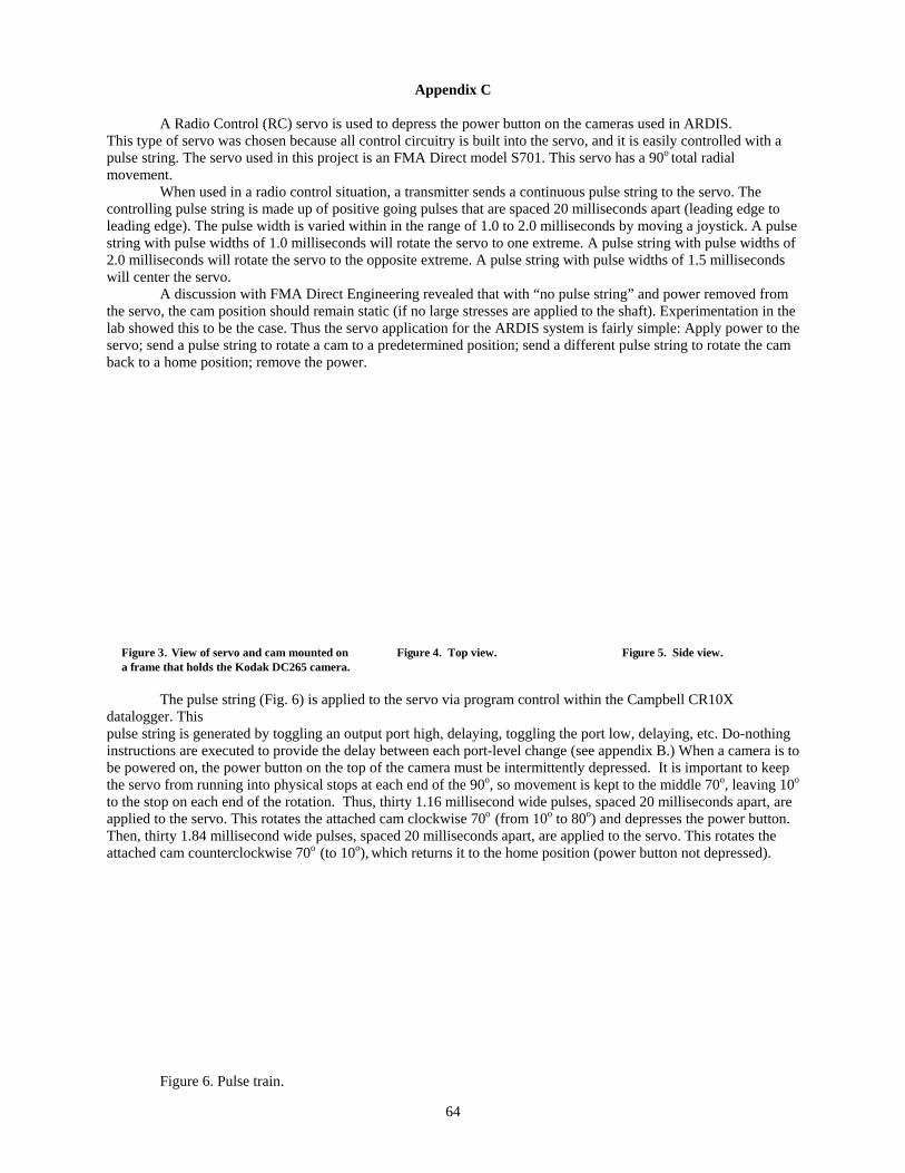
Appendix C
A Radio Control (RC) servo is used to depress the power button on the cameras used in ARDIS. This type of servo was chosen because all control circuitry is built into the servo, and it is easily controlled with a pulse string. The servo used in this project is an FMA Direct model S701. This servo has a 90o total radial movement.
When used in a radio control situation, a transmitter sends a continuous pulse string to the servo. The controlling pulse string is made up of positive going pulses that are spaced 20 milliseconds apart (leading edge to leading edge). The pulse width is varied within in the range of 1.0 to 2.0 milliseconds by moving a joystick. A pulse string with pulse widths of 1.0 milliseconds will rotate the servo to one extreme. A pulse string with pulse widths of 2.0 milliseconds will rotate the servo to the opposite extreme. A pulse string with pulse widths of 1.5 milliseconds will center the servo.
A discussion with FMA Direct Engineering revealed that with “no pulse string” and power removed from the servo, the cam position should remain static (if no large stresses are applied to the shaft). Experimentation in the lab showed this to be the case. Thus the servo application for the ARDIS system is fairly simple: Apply power to the servo; send a pulse string to rotate a cam to a predetermined position; send a different pulse string to rotate the cam back to a home position; remove the power.
Figure 3. View of servo and cam mounted on Figure 4. Top view. Figure 5. Side view. a frame that holds the Kodak DC265 camera.
The pulse string (Fig. 6) is applied to the servo via program control within the Campbell CR10X datalogger. This pulse string is generated by toggling an output port high, delaying, toggling the port low, delaying, etc. Do-nothing instructions are executed to provide the delay between each port-level change (see appendix B.) When a camera is to be powered on, the power button on the top of the camera must be intermittently depressed. It is important to keep the servo from running into physical stops at each end of the 90o, so movement is kept to the middle 70o, leaving 10o
to the stop on each end of the rotation. Thus, thirty 1.16 millisecond wide pulses, spaced 20 milliseconds apart, are applied to the servo. This rotates the attached cam clockwise 70o (from 10o to 80o) and depresses the power button. Then, thirty 1.84 millisecond wide pulses, spaced 20 milliseconds apart, are applied to the servo. This rotates the attached cam counterclockwise 70o (to 10o), which returns it to the home position (power button not depressed).
Figure 6. Pulse train.
64

The servo draws approximately 50 milliamps continuously when powered on and about 250 milliamps while rotating. Therefore, a relay is used to apply power to the servo prior to issuing a pulse string. When servo rotation is complete, the power is removed. This keeps the servo power requirement to a minimum. Keeping the power applied continuously would require 1.2 amps per day. This power savings is important in a remote battery powered situation. The power switching circuit is shown below.
Figure 7. RC servo power control
65

Appendix D
Power is supplied to the remote and unmanned ARDIS system by batteries and a solar panel (Fig. 8 and 9).
Figure 8. Power supply diagram showing battery, regulator, and solar panel.
The solar panel (10-watt) output is connected to the battery through a low-power-usage regulator. The regulator controls battery charging and maintains battery voltage at 14.6 volts or below and has a quiescent current of 2 milliamps. The power supply is in a separate environmental enclosure to keep the batteries away from the camera and associated electronics.
Figure 9. Power supply detail.
Power usage must be kept as low as possible. The components that require power are the camera, the servo, the datalogger and the anemometer. The camera has two voltage possibilities: 7-8 volts from the AC adapter; and 4.8 to 6 volts through the battery compartment. The datalogger nominally requires 12 volts, with a voltage range of 9.6 to 18 volts. The anemometer nominally requires 12 volts with a voltage range of 10-15 volts. The simpler way to connect power to the camera is through the AC adapter connector. But, that would require three separate voltages from the power supply and two regulators (7-8 volts and 4.8-6 volts.) Regulators consume power, so to conserve power it was decided to power the camera through the battery compartment. This reduces the requirement to two
66

voltages (12-volts for the datalogger and anemometer and 6-volts for camera and servo) and one regulator for the 6 volts. The 12-volts need not be regulated because of the wide voltage ranges for the datalogger and anemometer.
Twelve-volt power is regulated to six-volts within this enclosure (Fig. 10).
Figure 10. 6-volt regulator.
Six-volt and twelve-volt power are then run to each individual camera environmental enclosure, where the power is distributed within that enclosure (Fig. 11 and 12).
Figure 11. Diagram of power distribution within camera enclosure.
67
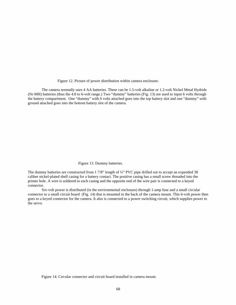
Figure 12. Picture of power distribution within camera enclosure.
The camera normally uses 4 AA batteries. These can be 1.5-volt alkaline or 1.2-volt Nickel Metal Hydride (Ni-MH) batteries (thus the 4.8 to 6-volt range.) Two “dummy” batteries (Fig. 13) are used to input 6 volts through the battery compartment. One “dummy” with 6 volts attached goes into the top battery slot and one “dummy” with ground attached goes into the bottom battery slot of the camera.
Figure 13. Dummy batteries.
The dummy batteries are constructed from 1 7/8” length of ¼” PVC pipe drilled out to accept an expended 38 caliber nickel-plated shell casing for a battery contact. The positive casing has a small screw threaded into the primer hole. A wire is soldered to each casing and the opposite end of the wire pair is connected to a keyed connector.
Six-volt power is distributed (in the environmental enclosure) through 1-amp fuse and a small circular connector to a small circuit board (Fig. 14) that is mounted in the back of the camera mount. This 6-volt power then goes to a keyed connector for the camera. It also is connected to a power switching circuit, which supplies power to the servo.
Figure 14. Circular connector and circuit board installed in camera mount.
68
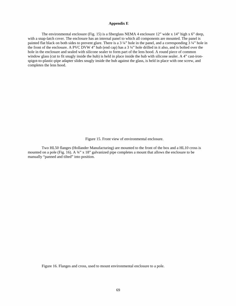
Appendix E
The environmental enclosure (Fig. 15) is a fiberglass NEMA 4 enclosure 12” wide x 14” high x 6” deep, with a snap-latch cover. The enclosure has an internal panel to which all components are mounted. The panel is painted flat black on both sides to prevent glare. There is a 3 ¼” hole in the panel, and a corresponding 3 ¼” hole in the front of the enclosure. A PVC DVW 4” hub (end cap) has a 3 ¼” hole drilled in it also, and is bolted over the hole in the enclosure and sealed with silicone sealer to form part of the lens hood. A round piece of common window glass (cut to fit snugly inside the hub) is held in place inside the hub with silicone sealer. A 4” cast-iron-spigot-to-plastic-pipe adapter slides snugly inside the hub against the glass, is held in place with one screw, and completes the lens hood.
Figure 15. Front view of environmental enclosure.
Two HL50 flanges (Hollander Manufacturing) are mounted to the front of the box and a HL10 cross is mounted on a pole (Fig. 16). A ¾” x 18” galvanized pipe completes a mount that allows the enclosure to be manually “panned and tilted” into position.
Figure 16. Flanges and cross, used to mount environmental enclosure to a pole.
69
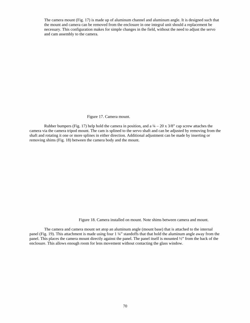
The camera mount (Fig. 17) is made up of aluminum channel and aluminum angle. It is designed such that the mount and camera can be removed from the enclosure in one integral unit should a replacement be necessary. This configuration makes for simple changes in the field, without the need to adjust the servo and cam assembly to the camera.
Figure 17. Camera mount.
Rubber bumpers (Fig. 17) help hold the camera in position, and a ¼ – 20 x 3/8” cap screw attaches the camera via the camera tripod mount. The cam is splined to the servo shaft and can be adjusted by removing from the shaft and rotating it one or more splines in either direction. Additional adjustment can be made by inserting or removing shims (Fig. 18) between the camera body and the mount.
Figure 18. Camera installed on mount. Note shims between camera and mount.
The camera and camera mount set atop an aluminum angle (mount base) that is attached to the internal panel (Fig. 19). This attachment is made using four 1 ¼” standoffs that that hold the aluminum angle away from the panel. This places the camera mount directly against the panel. The panel itself is mounted ½” from the back of the enclosure. This allows enough room for lens movement without contacting the glass window.
70

Figure 19. Internal panel with mount base.
The mount base (Fig. 19) also holds two fuses and a barrier strip. Power and signals attach to the barrier strip. Power is distributed to the camera and servo through a circular-connector, and to the datalogger (if one is in this particular enclosure) through a special Campbell connector.
If a datalogger is in the enclosure (master enclosure), it is mounted (Fig. 20) via four 6/32 x ½” stainless-steel screws (threads are tapped into the panel.)
Figure 20. Datalogger mounted in environmental enclosure.
The enclosure has a ground lug attached to the bottom so that the electronics can be attached to earth ground (Fig. 21). Communication with the datalogger is via a keyboard. Datalogger and camera functions can be accessed through keyboard communications.
71

Figure 21. Environmental enclosure with camera, datalogger, and keyboard.
72