Embed Size (px)
Citation preview
AUTOMATED REPAIR OF FIBER COMPOSITE STRUCTURES BASED ON 3D-SCANNING AND ROBOTIZED MILLING
B. Mann, iSAM AG, Mülheim, Germany C. Reich, GOM mbH, Braunschweig, Germany
Summary
The repair of fiber composite structures from airplanes and helicopters is a complex and expensive process. The aim of the project “Rapid Repair” is the development of an integrated process chain for a fast, automated and reproducible repair of high performance fiber composite structures. With the help of modern optical fringe projection technology the exterior shell of an aircraft can be scanned in 3D. For this, the company GOM has optimized the digitizing software and hardware for capturing materials which are typical in aircraft construction. After the scan data has been transformed into the coordinate system of the robot a software developed by iSAM AG jointly with the IFB, Stuttgart automatically generates the robot program not only for the scarfing itself but also for patch and tool generation.
1. 3D-SCANNING BY PHOTOGRAMMETRIC FRINGE PROJECTION
The used measurement principle for 3D-scanning is opti-cal triangulation. Fringe projection is used to create a unique coding for each point of the object surface (see Image 1). The calculation of 3D-coordinates is performed by identifying identical codes in both recording cameras and triangulation of the optical rays from the corresponding camera pixels through the known positions of the camera projection centers (optical triangulation) [1].
Image 1. Fringe projection and optical triangulation of coded object points
1.1. Non-cooperative object surfaces
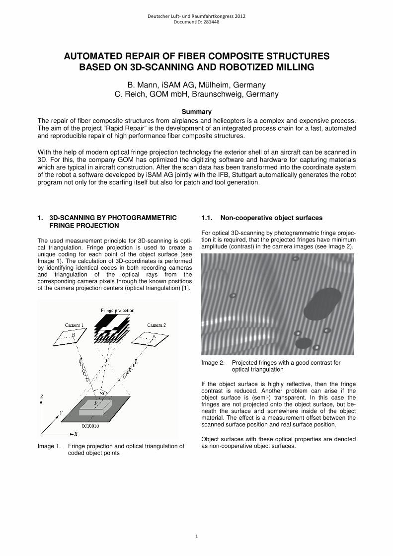
For optical 3D-scanning by photogrammetric fringe projec-tion it is required, that the projected fringes have minimum amplitude (contrast) in the camera images (see Image 2).
Image 2. Projected fringes with a good contrast for optical triangulation
If the object surface is highly reflective, then the fringe contrast is reduced. Another problem can arise if the object surface is (semi-) transparent. In this case the fringes are not projected onto the object surface, but be-neath the surface and somewhere inside of the object material. The effect is a measurement offset between the scanned surface position and real surface position.
Object surfaces with these optical properties are denoted as non-cooperative object surfaces.
Deutscher Luft- und Raumfahrtkongress 2012
1
DocumentID: 281448
1.2. Optical properties of carbon fiber and glass fiber composites
The high performance fiber composites structures con-sidered in this research project were carbon fibers and glass fibers. Different test measurement series of this surface materials have been realized by using the ATOS III Rev. 01 sensor, which was the latest sensor generation from GOM at the beginning of the project (see Image 3).
Image 3. ATOS III Rev. 01 sensor
The result of different test measurement series was that the carbon fiber surfaces could be measured with a sys-tematic offset of typically just -0,01mm which is negligible for the application.
On the other side, the measurements of the glass fiber surface probes showed a systematic offset from -0,2mm up to -0,5mm, which was not acceptable.
The reason for the offset is that the ATOS III Rev. 01 was using white light for the fringe projector and the light was penetrating the object surfaces.
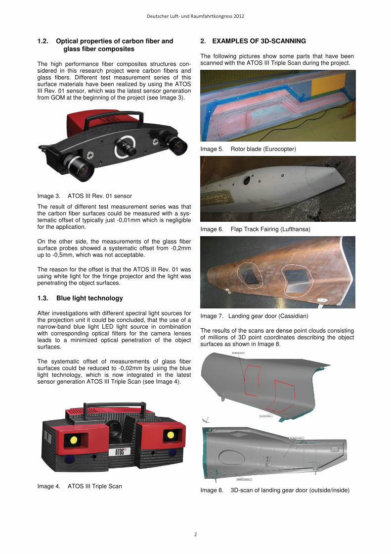
1.3. Blue light technology
After investigations with different spectral light sources for the projection unit it could be concluded, that the use of a narrow-band blue light LED light source in combination with corresponding optical filters for the camera lenses leads to a minimized optical penetration of the object surfaces.
The systematic offset of measurements of glass fiber surfaces could be reduced to -0,02mm by using the blue light technology, which is now integrated in the latest sensor generation ATOS III Triple Scan (see Image 4).
Image 4. ATOS III Triple Scan
2. EXAMPLES OF 3D-SCANNING
The following pictures show some parts that have been scanned with the ATOS III Triple Scan during the project.
Image 5. Rotor blade (Eurocopter)
Image 6. Flap Track Fairing (Lufthansa)
Image 7. Landing gear door (Cassidian)
The results of the scans are dense point clouds consisting of millions of 3D point coordinates describing the object surfaces as shown in Image 8.
Image 8. 3D-scan of landing gear door (outside/inside)
Deutscher Luft- und Raumfahrtkongress 2012
2
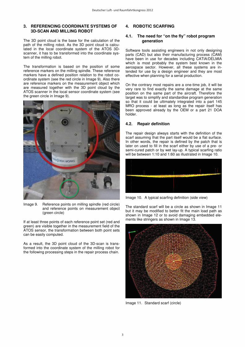
3. REFERENCING COORDINATE SYSTEMS OF 3D-SCAN AND MILLING ROBOT
The 3D point cloud is the base for the calculation of the path of the milling robot. As the 3D point cloud is calcu-lated in the local coordinate system of the ATOS 3D-scanner, it has to be transformed into the coordinate sys-tem of the milling robot.
The transformation is based on the position of some reference markers on the milling spindle. These reference markers have a defined position relation to the robot co-ordinate system (see the red circle in Image 9). Also there are reference markers on the measurement object which are measured together with the 3D point cloud by the ATOS scanner in the local sensor coordinate system (see the green circle in Image 9).
Image 9. Reference points on milling spindle (red circle) and reference points on measurement object (green circle)
If at least three points of each reference point set (red and green) are visible together in the measurement field of the ATOS sensor, the transformation between both point sets can be easily computed.
As a result, the 3D point cloud of the 3D-scan is trans-formed into the coordinate system of the milling robot for the following processing steps in the repair process chain.
4. ROBOTIC SCARFING
4.1. The need for “on the fly” robot program generation
Software tools assisting engineers in not only designing parts (CAD) but also their manufacturing process (CAM) have been in use for decades including CATIA/DELMIA which is most probably the system best known in the aerospace sector. However, all these systems are in-tended for use by a design engineer and they are most effective when planning for a serial production.
On the contrary most repairs are a one-time job, it will be very rare to find exactly the same damage at the same position on the same part of the aircraft. Therefore the target was to simplify and standardise program generation so that it could be ultimately integrated into a part 145 MRO process - at least as long as the repair itself has been approved already by the OEM or a part 21 DOA holder.
4.2. Repair definition
The repair design always starts with the definition of the scarf assuming that the part itself would be a flat surface. In other words, the repair is defined by the patch that is later on used to fill in the scarf either by use of a pre- or semi-cured patch or by wet lay-up. A typical scarfing ratio will be between 1:10 and 1:60 as illustrated in Image 10.
Image 10. A typical scarfing definition (side view)
The standard scarf will be a circle as shown in Image 11 but it may be modified to better fit the main load path as shown in Image 12 or to avoid damaging embedded ele-ments like stringers as shown in Image 13.
Image 11. Standard scarf (circle)
Deutscher Luft- und Raumfahrtkongress 2012
3
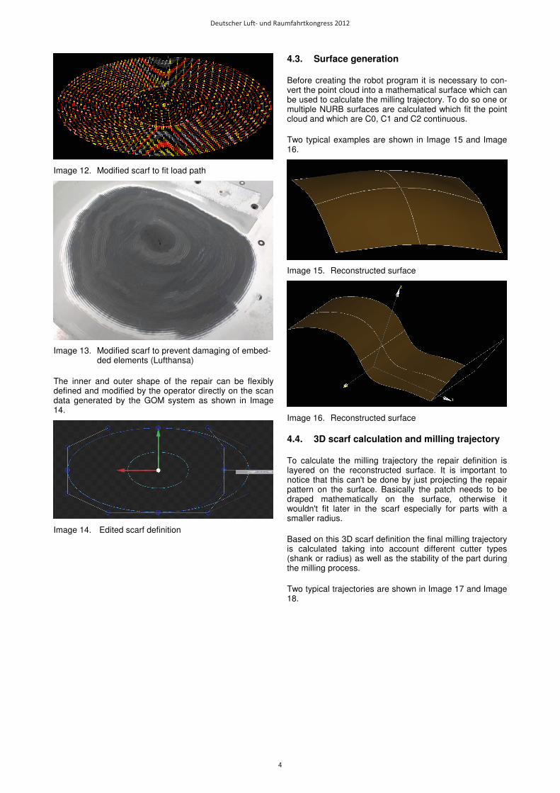
Image 12. Modified scarf to fit load path
Image 13. Modified scarf to prevent damaging of embed-ded elements (Lufthansa)
The inner and outer shape of the repair can be flexibly defined and modified by the operator directly on the scan data generated by the GOM system as shown in Image 14.
Image 14. Edited scarf definition
4.3. Surface generation
Before creating the robot program it is necessary to con-vert the point cloud into a mathematical surface which can be used to calculate the milling trajectory. To do so one or multiple NURB surfaces are calculated which fit the point cloud and which are C0, C1 and C2 continuous.
Two typical examples are shown in Image 15 and Image 16.
Image 15. Reconstructed surface
Image 16. Reconstructed surface
4.4. 3D scarf calculation and milling trajectory
To calculate the milling trajectory the repair definition is layered on the reconstructed surface. It is important to notice that this can't be done by just projecting the repair pattern on the surface. Basically the patch needs to be draped mathematically on the surface, otherwise it wouldn't fit later in the scarf especially for parts with a smaller radius.
Based on this 3D scarf definition the final milling trajectory is calculated taking into account different cutter types (shank or radius) as well as the stability of the part during the milling process.
Two typical trajectories are shown in Image 17 and Image 18.
Deutscher Luft- und Raumfahrtkongress 2012
4
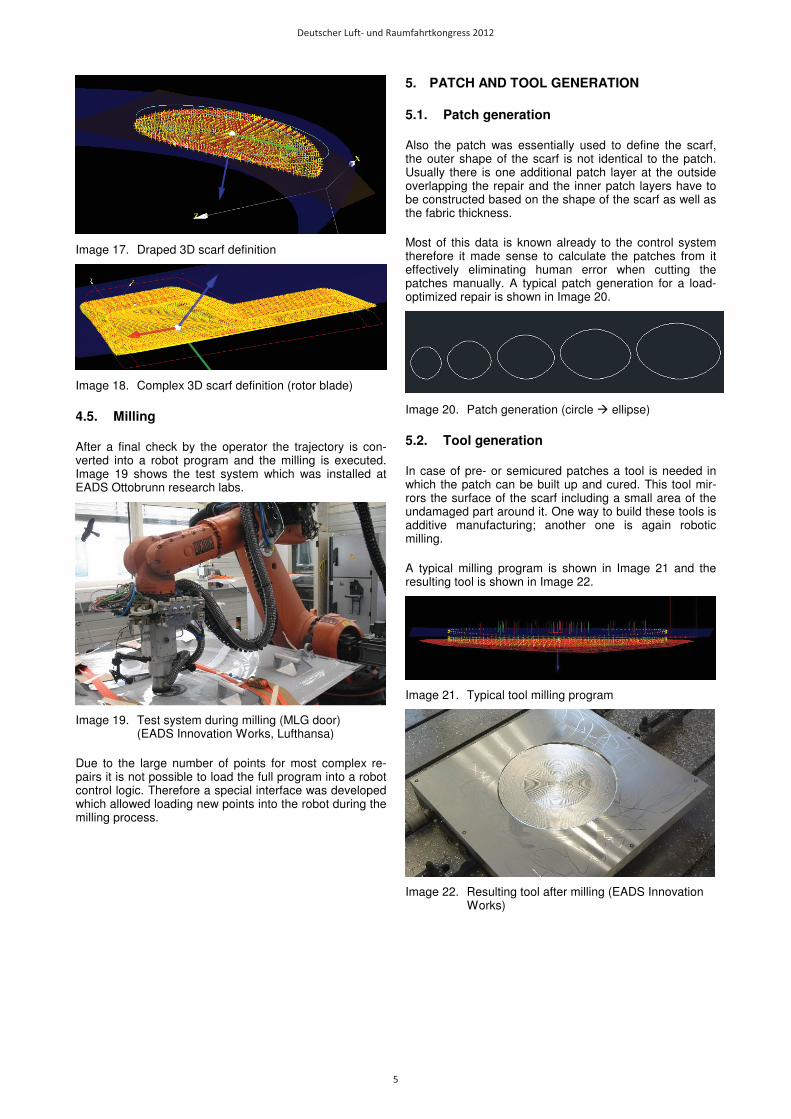
Image 17. Draped 3D scarf definition
Image 18. Complex 3D scarf definition (rotor blade)
4.5. Milling
After a final check by the operator the trajectory is con-verted into a robot program and the milling is executed. Image 19 shows the test system which was installed at EADS Ottobrunn research labs.
Image 19. Test system during milling (MLG door) (EADS Innovation Works, Lufthansa)
Due to the large number of points for most complex re-pairs it is not possible to load the full program into a robot control logic. Therefore a special interface was developed which allowed loading new points into the robot during the milling process.
5. PATCH AND TOOL GENERATION
5.1. Patch generation
Also the patch was essentially used to define the scarf, the outer shape of the scarf is not identical to the patch. Usually there is one additional patch layer at the outside overlapping the repair and the inner patch layers have to be constructed based on the shape of the scarf as well as the fabric thickness.
Most of this data is known already to the control system therefore it made sense to calculate the patches from it effectively eliminating human error when cutting the patches manually. A typical patch generation for a load-optimized repair is shown in Image 20.
Image 20. Patch generation (circle � ellipse)
5.2. Tool generation
In case of pre- or semicured patches a tool is needed in which the patch can be built up and cured. This tool mir-rors the surface of the scarf including a small area of the undamaged part around it. One way to build these tools is additive manufacturing; another one is again robotic milling.
A typical milling program is shown in Image 21 and the resulting tool is shown in Image 22.
Image 21. Typical tool milling program
Image 22. Resulting tool after milling (EADS Innovation Works)
Deutscher Luft- und Raumfahrtkongress 2012
5
6. PRACTICAL TESTS AND OPERATIONAL EVALUATION
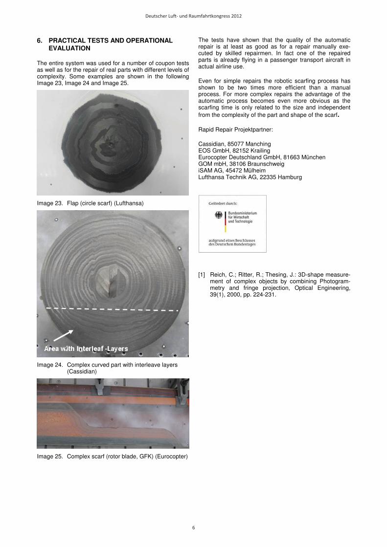
The entire system was used for a number of coupon tests as well as for the repair of real parts with different levels of complexity. Some examples are shown in the following Image 23, Image 24 and Image 25.
Image 23. Flap (circle scarf) (Lufthansa)
Image 24. Complex curved part with interleave layers (Cassidian)
Image 25. Complex scarf (rotor blade, GFK) (Eurocopter)
The tests have shown that the quality of the automatic repair is at least as good as for a repair manually exe-cuted by skilled repairmen. In fact one of the repaired parts is already flying in a passenger transport aircraft in actual airline use.
Even for simple repairs the robotic scarfing process has shown to be two times more efficient than a manual process. For more complex repairs the advantage of the automatic process becomes even more obvious as the scarfing time is only related to the size and independent from the complexity of the part and shape of the scarf.
Rapid Repair Projektpartner:
Cassidian, 85077 Manching EOS GmbH, 82152 Krailing Eurocopter Deutschland GmbH, 81663 München GOM mbH, 38106 Braunschweig iSAM AG, 45472 Mülheim Lufthansa Technik AG, 22335 Hamburg
[1] Reich, C.; Ritter, R.; Thesing, J.: 3D-shape measure-ment of complex objects by combining Photogram-metry and fringe projection, Optical Engineering, 39(1), 2000, pp. 224-231.
Deutscher Luft- und Raumfahrtkongress 2012
6