Embed Size (px)
Citation preview

AUTOMATED SYSTEM ARCHITECTURE FOR CONTAINER- BASED
AND HYPERVISOR-BASED VIRTUALIZATION
MUHAMMAD AMIN BIN ABDUL RAZAK
FACULTY OF COMPUTER SCIENCE & INFORMATION
TECHNOLOGY
UNIVERSITY OF MALAYA
KUALA LUMPUR
2019
Univers
ity of
Mala
ya

AUTOMATED SYSTEM ARCHITECTURE FOR CONTAINER-
BASED AND HYPERVISOR-BASED VIRTUALIZATION
MUHAMMAD AMIN BIN ABDUL RAZAK
DISSERTATION SUBMITTED IN PARTIAL FULFILMENT OF
THE REQUIREMENTS FOR THE DEGREE OF MASTER OF
COMPUTER SCIENCE
FACULTY OF COMPUTER SCIENCE AND INFORMATION
TECHNOLOGY
UNIVERSITY OF MALAYA
KUALA LUMPUR
2019
Univers
ity of
Mala
ya
ii
UNIVERSITY OF MALAYA
ORIGINAL LITERARY WORK DECLARATION
Name of Candidate: (I.C/Passport No: )
Matric No:
Name of Degree:
Title of Project Paper/Research Report/Dissertation/Thesis (“this Work”):
Field of Study:
I do solemnly and sincerely declare that:
(1) I am the sole author/writer of this Work; (2) This Work is original; (3) Any use of any work in which copyright exists was done by way of fair dealing
and for permitted purposes and any excerpt or extract from, or reference to or reproduction of any copyright work has been disclosed expressly and sufficiently and the title of the Work and its authorship have been acknowledged in this Work;
(4) I do not have any actual knowledge nor do I ought reasonably to know that the making of this work constitutes an infringement of any copyright work;
(5) I hereby assign all and every rights in the copyright to this Work to the University of Malaya (“UM”), who henceforth shall be owner of the copyright in this Work and that any reproduction or use in any form or by any means whatsoever is prohibited without the written consent of UM having been first had and obtained;
(6) I am fully aware that if in the course of making this Work I have infringed any copyright whether intentionally or otherwise, I may be subject to legal action or any other action as may be determined by UM.
Candidate’s Signature Date:
Subscribed and solemnly declared before,
Witness’s Signature Date:
Name:
Designation:
Univers
ity of
Mala
ya
iii
ABSTRACT
Virtualization allows multiple operating systems and applications to be executed on the
same physical server concurrently. Recently, two popular virtualization platforms, namely
container-based and hypervisor-based were adapted into most data centers to support
cloud services. With the increase in various types of scientific workflow applications in
the cloud, low-overhead virtualization techniques are becoming indispensable. However,
to deploy the workflow tasks to a suitable virtualization platform in the cloud is a
challenge. It requires intimate knowledge of ever-changing workflow tasks at any given
moment. This research proposed an automated system architecture that can choose the
best virtualization platform to execute workflow tasks. A benchmark performance
evaluation was conducted on various workflow tasks running on container-based and
hypervisor-based virtualization. Several tools were used to measure the metric, such as
central processing unit (CPU), memory, input and output (I/O). Based on the benchmark,
a system architecture was created to automate the virtualization platform selection. The
results showed that the proposed architecture minimized the workflows’ total execution
time.
Univers
ity of
Mala
ya
iv
ABSTRAK
Virtualisasi membolehkan sistem operasi dan aplikasi berganda yang akan dilaksanakan
pada pelayan fizikal yang sama secara serentak. Baru-baru ini, dua platform virtualisasi
popular, iaitu berasaskan kontena dan berasaskan hypervisor telah disesuaikan kepada
kebanyakan pusat data untuk menyokong perkhidmatan awan. Dengan peningkatan
pelbagai jenis aplikasi alur kerja saintifik di awan, teknik maya kos rendah adalah sangat
diperlukan. Walau bagaimanapun, ia merupakan satu cabaran untuk menggunakan tugas
aliran kerja kepada platform virtualisasi yang sesuai di awan. Oleh kerana tugas aliran
kerja sering berubah, ia memerlukan pengetahuan mendalam. Penyelidikan ini
mencadangkan suatu senibina sistem automatik yang dapat memilih platform virtualisasi
terbaik untuk melaksanakan tugas aliran kerja. Penilaian prestasi penanda aras telah
dijalankan terhadap pelbagai tugas aliran kerja yang dijalankan pada virtualisasi
berasaskan kontena dan berasaskan hypervisor. Beberapa peralatan digunakan untuk
mengukur metrik seperti unit pemprosesan, memori, input dan output (I /O). Berdasarkan
penanda aras, senibina sistem telah diwujudkan untuk mengautomasikan pemilihan
platform virtualisasi. Keputusan menunjukkan bahawa senibina yang dicadangkan
meminimumkan jumlah masa pelaksanaan aliran kerja.
Univers
ity of
Mala
ya

v
ACKNOWLEDGEMENTS
My sincere appreciation goes to my supervisor Dr Ang Tan Fong for his support,
guidance, encouragement and assistance. I appreciate and feel thankful to have him as my
supervisor. I would also like to thank Siti Roaiza and Audie Afham for their professional
assistance during this research work. My deepest gratitude and appreciation go to my
parents Abdul Razak Bin Abdul Hamid and also Ramlah Binti Hashim for the support
they have given me throughout. Their assistance has been much felt and their support and
courage has made all the difference, thank you.
Univers
ity of
Mala
ya
vi
TABLE OF CONTENTS
Abstract… .................................................................................................... iii
Abstrak. ....................................................................................................... iv
Acknowledgements… ................................................................................. v
Table of Contents… ..................................................................................... vi
List of Figures……………………………………………………………...x
List of Tables……………………………………………………………..xiii
List of Symbols and Abbreviations……………………………………….xiv
Chapter 1 ................................................................................................... 1
1.1 Background ........................................................................................... 1
1.2 Problem Statement ................................................................................ 7
1.3 Objectives .............................................................................................. 8
1.4 Scope ..................................................................................................... 9
1.5 Dissertation Organisation ...................................................................... 9
Chapter 2 ................................................................................................... 11
2.1 Virtualizations ....................................................................................... 11
2.1.1 Hypervisor .................................................................................. 12
2.1.2 Containers ................................................................................... 14
2.2 Performance Evaluation ........................................................................ 15
2.2.1 Performance Evaluation Tools ................................................... 24
2.2.1.1 Bonnie++ ..................................................................... 24
Univers
ity of
Mala
ya

vii
2.2.1.2 Sysbench ...................................................................... 25
2.2.1.3 Y-Cruncher… .............................................................. 25
2.2.1.4 STREAM Benchmarking Tools… .............................. 26
Univers
ity of
Mala
ya
viii
2.3 Resource Management .......................................................................... 27
2.4 Docker-Sec Automation Architecture ................................................... 33
2.4 Workflow .............................................................................................. 34
2.4.1 Workflow Orchestration.............................................................36
2.4.2 Workflow Scheduling ................................................................ 36
2.4.3 Workflow Deployment...............................................................36
2.5 Chapter Summary ................................................................................. 38
Chapter 3 ................................................................................................... 41
3.1 DoKnowMe Methodology .................................................................... 41
3.1.1 Requirement Recognition............................................................44
3.1.2 Performance Feature Identification ............................................ 44
3.1.3 Metrics and Benchmarks Listing ................................................ 45
3.1.4 Metrics and Benchmarks Selection ............................................ 45
3.1.5 Experimental Factor Listings ..................................................... 45
3.1.6 Experimental Factors Selection..................................................46
3.1.7 Experimental Design ................................................................. 46
3.1.8 Experimental Implementation ................................................... 47
3.1.9 Experimental Analysis .............................................................. 47
3.1.10 Conclusion and Documentation .............................................. 47
3.2 Chapter Summary.................................................................................48
Univers
ity of
Mala
ya

ix
Chapter 4 ................................................................................................... 49
4.1 Automated System Architecture ........................................................... 49
4.2 System Implementation ......................................................................... 55
4.2.1 Performance Database ................................................................ 55
4.2.1.1 Compute Performance Testing
Using Sysbench .............................................. 55
4.2.1.1.1 Compute Performance Testing
Using Bonnie++ ............................................ 56
4.2.1.2 Memory Performance Testing ......................................58
4.2.1.3 I/O Performance Testing
Using Sysbench. ........................................... 58
4.2.1.3.1 I/O Performance Testing
Using Bonnie++ ........................................... 60
4.2.2 Web Form.................................................................................... 61
4.2.3 Orchestration Component ........................................................... 62
4.2.4 Scheduling Component ............................................................... 63
4.2.5 Deployment Component .............................................................. 64
4.3 System Testing ....................................................................................... 64
4.4 Chapter Summary .................................................................................. 65
Chapter 5 .................................................................................................... 66
5.1 Experimental Setup .................................................................................66
Univers
ity of
Mala
ya

x
5.2 Experimental Results ............................................................................. 68
5.3 Chapter Summary .................................................................................. 71
Chapter 6 .................................................................................................... 72
6.1 Thesis Summary ................................................................................... 72
6.2 Thesis Contribution .............................................................................. 73
6.3 Future Work Suggestions ..................................................................... 74
REFERENCES .......................................................................................... 75
Univers
ity of
Mala
ya
x
LIST OF FIGURES
Figure 1.1: Virtualization adoption trend .................................................. 1
Figure 1.2: Hypervisor-based virtualization .............................................. 2
Figure 1.3: Container-based virtualization ................................................ 3
Figure 1.4: Major component in docker engine .........................................5
Figure 2.1: Scheme of hypervisor-based virtualization
(Michael Eder, 2016) .............................................................. 13
Figure 2.2: Container-based architecture in terms of managing its
Operating system (C. Pahl, 2014) ........................................... 15
Figure 2.3: Container image architecture based on namespace and
cgroup Extension (Claus Pahl, 2015) ...................................... 16
Figure 2.4: Performance result of the Y-cruncher benchmarking
Tools (Zhanibek Kozhirbayev, 2017) ................................... 18
Figure 2.5: STREAM result (Zhanibek Kozhirbayev, 2017) ..................... 19
Figure 2.6 LINPACK on Ubuntu (Helen Karatza, 2017) ......................... 20
Figure 2.7 LINPACK on CentOS (Helen Karatza, 2017) ......................... 20
Figure 2.8 STREAM on Ubuntu (Helen Karatza, 2017) ........................... 21
Figure 2.9 STREAM on CentOS (Helen Karatza, 2017) .......................... 22
Figure 2.10 NETPERF, TCP_STREAM
on Ubuntu (Helen Karatza, 2017) ............................................ 23
Figure 2.11. NETPERF, TCP_STREAM
Univers
ity of
Mala
ya
xi
on Ubuntu (Helen Karatza, 2017) ............................................ 23
Figure 2.12: A Cloud orchestration layer oversees the infrastructure
Supporting live migration of containers
(David S. Linthicum, 2016) ..................................................... 28
Figure 2.13: Computing performance by using Linpack for Matrices
(Miguel et al., 2013) ................................................................. 29
Figure 2.14: Memory throughput by using STREAM (Miguel et al., 2013).31
Figure 2.15: Disk throughput by using IOZone (Miguel et al., 2013)………32
Figure 2.16 Docker Components Protected with
AppArmor in Docker-Sec (Fotis Loukidis, 2018) ...................... 33
Figure 2.17: Common workflow in scientific
Experiments (Paul Martin et al., 2016) ...................................... 35
Figure 3.1: The relationship between DoKnowMe and its
Instance Methodologies ............................................................ 42
Figure 3.2: The step-by-step procedure by using DoKnowMe .................... 43
Figure 4.1: Automated system architecture .................................................. 49
Figure 4.2: Workflow categorisations .......................................................... 51
Figure 4.3: Use case diagram ........................................................................52
Figure 4.4: System flow ............................................................................... 54
Figure 4.5: Compute performance testing Using Sysbench. ........................ 56
Univers
ity of
Mala
ya
xii
Figure 4.6: Compute performance testing Using Bonnie++ ..........................57
Figure 4.7: Memory performance testing ..................................................... 58
Figure 4.8: I/O performance testing Using Sysbench. .................................. 59
Figure 4.9 I/O performance testing Bonnie++ ............................................. 60
Figure 4.10: Web form ................................................................................... 61
Figure 4.10: Workflow specifications ............................................................ 62
Figure 5.1: Compute intensive workflow execution time result .................. 68
Figure 5.2: Memory intensive workflow execution time result ................... 69
Figure 5.3: I/O intensive workflow execution time result ........................... 70
Figure 5.4: Uniform workflow execution time result .................................. 71
Univers
ity of
Mala
ya
xiii
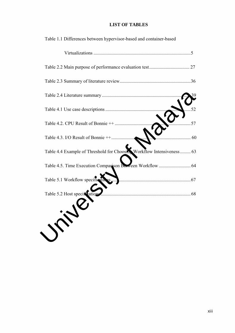
LIST OF TABLES
Table 1.1 Differences between hypervisor-based and container-based
Virtualizations .................................................................................. 5
Table 2.2 Main purpose of performance evaluation test .................................. 27
Table 2.3 Summary of literature review ............................................................ 36
Table 2.4 Literature summary ........................................................................... 39
Table 4.1 Use case descriptions ........................................................................ 52
Table 4.2. CPU Result of Bonnie ++ ................................................................ 57
Table 4.3. I/O Result of Bonnie ++ ................................................................... 60
Table 4.4 Example of Threshold for Choosing Workflow Intensiveness ......... 63
Table 4.5. Time Execution Comparison Between Workflow ........................... 64
Table 5.1 Workflow specifications ................................................................... 67
Table 5.2 Host specifications ............................................................................ 68
Univers
ity of
Mala
ya
xiv
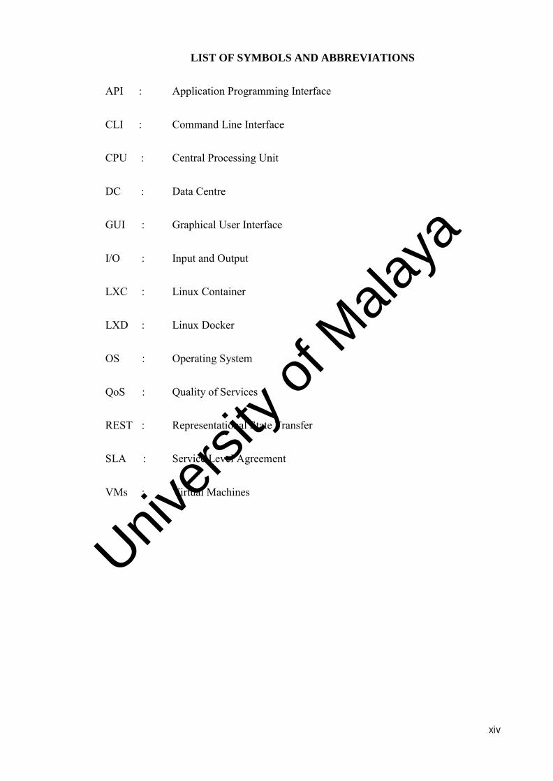
LIST OF SYMBOLS AND ABBREVIATIONS
API : Application Programming Interface
CLI : Command Line Interface
CPU : Central Processing Unit
DC : Data Centre
GUI : Graphical User Interface
I/O : Input and Output
LXC : Linux Container
LXD : Linux Docker
OS : Operating System
QoS : Quality of Services
REST : Representational State Transfer
SLA : Service Level Agreement
VMs : Virtual Machines
Univers
ity of
Mala
ya
1
CHAPTER 1: INTRODUCTION
This chapter begins with a background study on the container-based and hypervisor-
based virtualization. Then, the challenges of the virtualizations are presented, leading to
the problem statements. Subsequently, the research objectives and scopes are
subsequently stated. Finally, the dissertation organisation is presented at the end of the
chapter.
1.1 Background
Virtualization is a software that isolates physical infrastructures to create numerous
dedicated resources. Virtualization makes it doable to run several operating systems and
applications on similar server. The benefit of virtualizations is on the server-side, where
the virtualization itself reduces maintenance and energy costs as well as the number of
physical servers. By sharing resources in the physical servers, virtualization becomes the
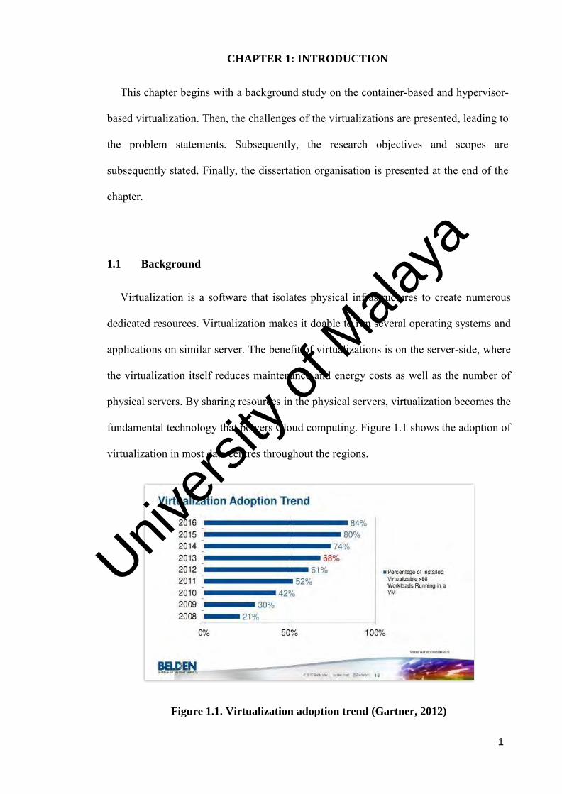
fundamental technology that powers Cloud computing. Figure 1.1 shows the adoption of
virtualization in most data centres throughout the regions.
Figure 1.1. Virtualization adoption trend (Gartner, 2012)
Univers
ity of
Mala
ya
2
Virtualization plays a vital role in supporting Cloud services from resource
provisioning to isolating the resources. There are two popular types of virtualization
platform, namely the hypervisor-based and the container-based. The hypervisor-based
virtualization can be divided into the bare-metal hypervisor that is usually installed
straight forwardly onto the server, and the hosted hypervisor that requires a host operating
system (OS).
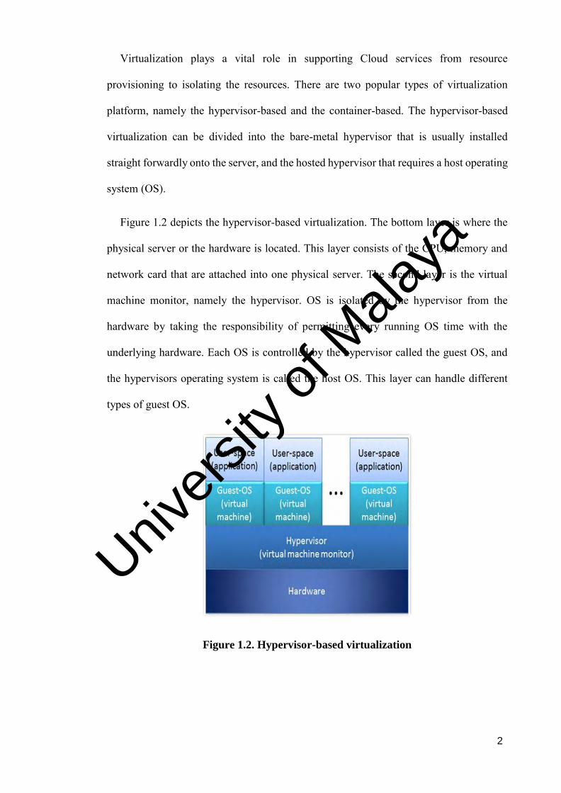
Figure 1.2 depicts the hypervisor-based virtualization. The bottom layer is where the
physical server or the hardware is located. This layer consists of the CPU, memory and
network card that are attached into one physical server. The second layer is the virtual
machine monitor, namely the hypervisor. OS is isolated by the hypervisor from the
hardware by taking the responsibility of permitting every running OS time with the
underlying hardware. Each OS is controlled by the hypervisor called the guest OS, and
the hypervisors operating system is called the host OS. This layer can handle different
types of guest OS.
Figure 1.2. Hypervisor-based virtualization
Univers
ity of
Mala
ya
3
The third layer is the virtual machine OS that is managed by the hypervisor itself. All
these virtual machines have their own services and libraries. The applications are installed
on each of the respective virtual machine. This virtualization allows users to virtualize
many operating systems in one piece of hardware.
To reduce the performance overhead of hypervisor-based virtualization, professionals
and specialists as of late began advancing an option and lightweight plans, namely the
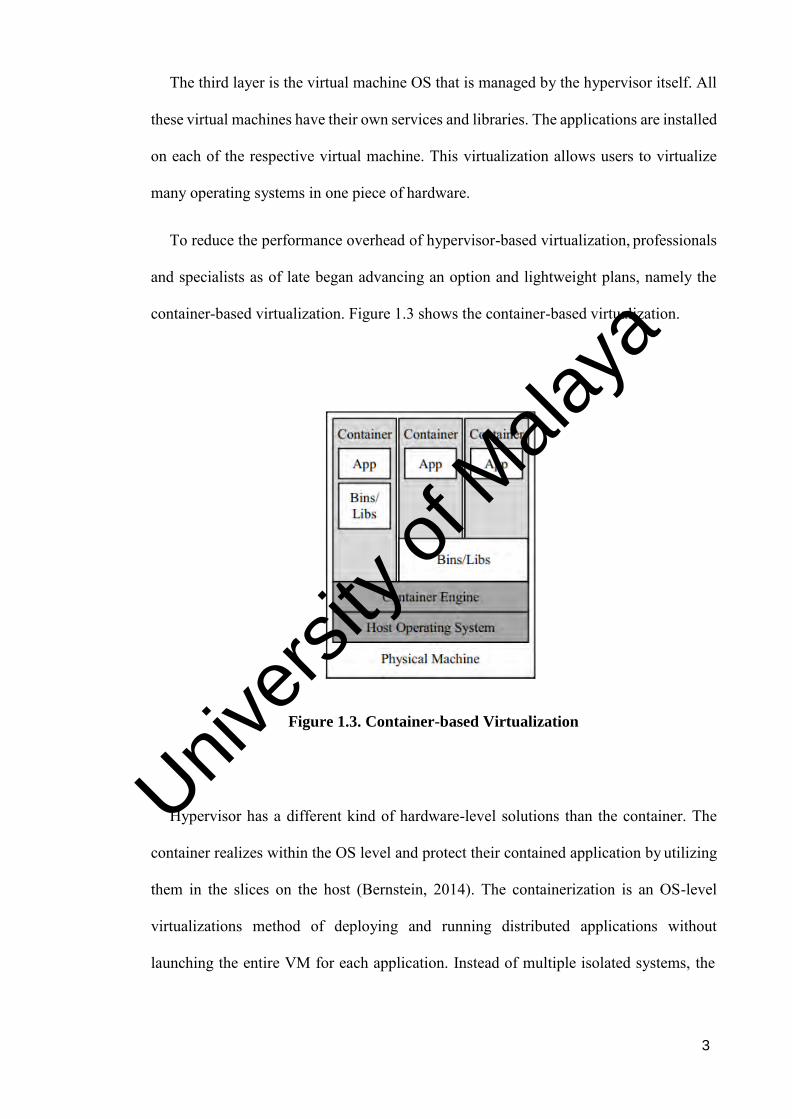
container-based virtualization. Figure 1.3 shows the container-based virtualization.
Figure 1.3. Container-based Virtualization
Hypervisor has a different kind of hardware-level solutions than the container. The
container realizes within the OS level and protect their contained application by utilizing
them in the slices on the host (Bernstein, 2014). The containerization is an OS-level
virtualizations method of deploying and running distributed applications without
launching the entire VM for each application. Instead of multiple isolated systems, the
Univers
ity of
Mala
ya

4
container is executed on a single control host and accessing a single kernel. There are a
few types of container-based virtualization such as Docker, LXD and lmctfy.
Container that is introduced by Docker is a free-source platform for user to develop
their software. The benefit of the docker is it can group the application to become a
package in “container” allowing them to be moveable among any system running the
Linux OS. Docker splits the applications from the infrastructure to speed up the time
taken for software deployment. Docker architecture consist of Docker engine which
responsible for client-server application. There are some major components in the engine,
namely daemon process which is a type of zero-downtime running program, the
Representational State Transfer (REST) application programming interface (API) which
specifies screens that enable programs to talk to the daemon and send command on what
to do. A command line interface is important to configure, build and maintain the Docker
environment. The command line interface (CLI) enables Docker REST API to manage or
communicate with the Docker daemon through scripting or one-to-one CLI commands.
Besides, there are some other Docker applications that use the underlying API and CLI
which are shown in Figure 1.4. The daemon manages Docker objects, such as image, data
volumes, network and container.
Univers
ity of
Mala
ya

5
Figure 1.4. Major component in Docker engine
Table 1.1 Differences between hypervisor-based and container-based
virtualizations
Hypervisor-based Container-based
VM contain a full operating system with
their own management of memory installed
with the mixed overhead of device drivers
virtually.
Containers are executed with the
compute engine. Containers comes
with more portable and less in size
than VM and enables fast start-up
with optimum execution.
Every virtual machine has their own
services and have their own personal
libraries
Single kernel can be shared in a
container and at the same time share
the same application libraries.
Fully loaded with resources and heavy and
consume time to create and launch VM
Faster and less heavy resources and
very reliable on fast start-up and
launching
Univers
ity of
Mala
ya
6
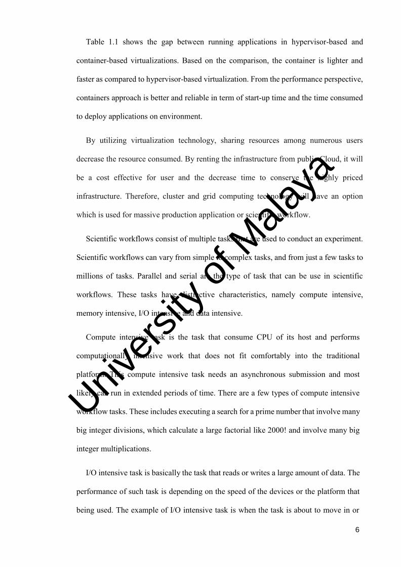
Table 1.1 shows the gap between running applications in hypervisor-based and
container-based virtualizations. Based on the comparison, the container is lighter and
faster as compared to hypervisor-based virtualization. From the performance perspective,
containers approach is better and reliable in term of start-up time and the time consumed
to deploy applications on environment.
By utilizing virtualization technology, sharing resources among numerous users
decrease the resource consumed. By renting the infrastructure from public Cloud, it will
be a cost effective for user and the decrease time to conserve the highly priced
infrastructure. Therefore, cluster and grid computing technology will have an option
which is used for massive production application or scientific workflow.
Scientific workflows consist of multiple tasks that are used to conduct an experiment.
Scientific workflows can vary from simple to complex tasks, and from just a few tasks to
millions of tasks. Parallel and serial are the type of task that can be use in scientific
workflows. These tasks have distinctive characteristics, namely compute intensive,
memory intensive, I/O intensive and data intensive.
Compute intensive task is the task that consume CPU of its host and performs
computationally intensive work that does not fit comfortably into the traditional
platform. This compute intensive task needs an asynchronous submission and most
likely can run in extended periods of time. There are a few types of compute intensive
workflow tasks. These includes executing a search for a prime number that involve many
big integer divisions, which calculate a large factorial like 2000! and involve many big
integer multiplications.
I/O intensive task is basically the task that reads or writes a large amount of data. The
performance of such task is depending on the speed of the devices or the platform that
being used. The example of I/O intensive task is when the task is about to move in or
Univers
ity of
Mala
ya
7
out from the computer. The data size will affect the host I/O performance. The I/O
process needs high bandwidth in order to have a stable throughput. The second task
would be reading the data in bytes. This kind of task will consume I/O because it needs
to perform operation in the logical disk itself and the lower the number of disk operation,
the higher the input and output per second capacity.
The memory intensive task usually needs to perform analysis or searching in large
scale of data. Big data application is the new trend of memory intensive task. This task
usually needs to perform data mining and data analytic that involve a large dataset.
During the process of data analytics, it typically starts with some large raw datasets, and
then the applications will transform, clean and prepare the dataset for modelling with
some sort of SQL-Like transformations. This will eventually utilize all memory that is
assigned in the host.
In conclusion, different type of tasks can affect the performance of the virtualization.
There is a need to conduct a performance analysis in virtualization that focuses on
compute, memory and I/O, to improve the performance of these virtualized systems.
1.2 Problem Statement
Almost all of the scientific workflows have increased the number of Cloud computing
paradigm, the techniques for virtualization such as low-overhead are becoming
indispensable (Plauth, 2017). Although the container virtualization is a lightweight
approach to execute these applications, it is very challenging in this unique environment
to comprehend what will affect the workflow performance as it requires a lot of
information and knowledge of the ever-changing application structure at any given
moment. Based on (Cedia, 2017), the hardware resources of Cloud computing are always
Univers
ity of
Mala
ya
8
limited, for this reason it is important that the available resources are adequately allocated
according to the application behaviour to obtain the best possible performance.
Furthermore, such Cloud platforms have for most part were deployed to web-based
platform and production applications, there is some portion that has dependencies and
need to be overseen to run scientific workflows, particularly all the data intensive
scientific workflows on the Cloud. Cloud computing provides an outlook changing and
computing standard in terms of the extraordinary size of datacentre-level resource pool
and provisions the on-demand resource mechanism, capable of addressing a large scale of
scientific problems to capacitate scientific workflow explications.
Virtualization environments are flexible and unique by design, rapid changes on
regular. Deploying a scientific workflow is risky, as minor differences in library versions
on different servers can break the functionality of the workflow.
According to (Felter, 2014), every virtual machine that runs on Linux operating system
have their own process and resource management abilities. One of the resource
management is scheduling that is exported to the virtual machines. This reduce the
administration and execution time but complicates resource management within the guest
operating system. Every scientific workflow has its own requirements for it to run
optimally. A new layer of complexity is added and can cause unfamiliar problems.
Furthermore, each scientific workflow will consume the compute, memory, I/O and
network of its host.
1.3 Objectives
This study aims to propose an automated system architecture that was able to choose
the best virtualization platform to execute the workflow tasks. The benchmark
Univers
ity of
Mala
ya

9
performance evaluation was conducted on various workflow tasks, running on hypervisor-
based and container-based virtualization to improve the selection decision.
The objectives of this research are outlined as follows:
- To conduct performance evaluation of workflow tasks running on container-based
and hypervisor-based virtualization.
- To design an automated system architecture that choose the suitable virtualization
platform for different workflow tasks.
- To evaluate the performance of various type of scientific workflows running on
those virtualization platforms.
1.4 Scope
The research only focuses on hypervisor-based and container-based virtualization. The
workflow tasks used for the evaluation are mainly compute-intensive, memory-intensive
and I/O intensive. The tools used for the evaluation consist of open source and commercial
tools. These tools must be able to measure the metric required and return the output of the
performance test.
1.5 Dissertation Organisation
This section provides a general overview of the chapters that make up this dissertation.
Chapter 1 contains the introduction to the topic in which the research is concerned with,
and the problem statements are outlined. The objectives of the study, the scope as well as
the structure of the dissertation are outlined.
Univers
ity of
Mala
ya
10
Chapter 2 describes the literature relevant to the research topic. First, the hypervisor-
based and container-based virtualizations are discussed. Then, the related works, focusing
on the performance evaluation are reviewed. After that, the performance tools that used
for the research are explained. Subsequently, the study of workflow orchestration,
scheduling and development are briefly discussed. The chapter ends with a summary that
concludes the findings.
Chapter 3 discusses the research techniques used in the dissertation. The chapter begins
with an introduction of the research flow that was used to conduct the research. The
research phases, such as information gathering and analysis, proposed method, system
design and implementation, system evaluation and documentation are discussed in detail
in the subsequent sections of the chapter.
Chapter 4 discusses the system design, implementation and testing of the proposed
technique. This chapter begins with the discussion of the proposed system architecture.
Then, the system implementation and testing are presented.
Chapter 5 explains the process of evaluating the proposed techniques and a detailed
discussion of the results. The performance tests were carried out in two different
environments, namely hypervisor-based and container-based virtualizations. The chapter
ends with a summary.
Chapter 6 concludes the research findings and achievements. The chapter begins with
a discussion on how the objectives were obtained. Then, the chapter presents the research
significance. Subsequently, the limitations and suggestions for future work are discussed.
Univers
ity of
Mala
ya
11
CHAPTER 2: LITERATURE REVIEW
This chapter starts with a discussion about the virtualizations. There are two types of
virtualization technology, namely hypervisor-based and container-based. Then, the
chapter continues with a discussion on performance evaluation techniques and the
performance tools. After that, the resource management concept is discussed.
Subsequently the workflow is deeply briefed, and the types of workflow are discussed.
Lastly, the chapter ends with a summary.
2.1 Virtualizations
Kumar (2015), said that virtualization plays an important role in Cloud computing and
becomes the important key to the cloud infrastructure, as the technology can be enabled,
the underlying hardware and software that are complex can be created as an intelligent
abstraction layer hidden in the environment itself. There are two types of virtualization
technologies namely the hypervisor-based and container-based virtualization technology.
In general, there are several kinds of use cases for virtualization and basically both
container-based and hypervisor-based virtualizations technology have strengths and
weaknesses based on the respective use cases.
Anish Babu (2014) mentioned, there are three kind of virtualization technology which
is Para virtualization, Container virtualization and Full virtualization. Para virtualization
is a technique in which the guest operating system is aware that they are operating directly
on the hypervisor instead of the underlying hardware. In Para virtualization, the
virtualization supporting hypervisor is installed on the host operating system which runs
over the underlying hardware. The second one is the Container virtualization. The
Container virtualization is a technique in which each operating system kernel is modified
to load multiple guest operating systems. Here guest operating systems are packed in the
Univers
ity of
Mala
ya
12
form of containers and each container will be allowed to load one by one. The kernel
provides proper management of the underlying resources to isolate one container activity
from the other. This type of virtualization technique has less overhead in loading the guest
operating system in the form of containers and each container has their own IP address,
memory and root access. The last one is Full virtualization. In Full virtualization,
hypervisor supporting the full virtualization technique is installed directly over the
underlying hardware. This hypervisor is responsible for loading the guest operating
systems. And each guest operating system will run as if they are operating directly on the
underlying hardware. That is each guest operating system will get all the features of the
underlying hardware. Here hypervisor will directly interact with the underlying memory
and disk space and hypervisor will isolate the activities of one guest operating system
from the other. Hypervisors supporting full virtualization have a virtual machine
management console from which each guest virtual machines can be easily managed.
2.1.1 Hypervisor
Desai (2013), said that Hypervisor allows user to run multiple OS on the same
hardware and it will abstract the software layer from the OS. The virtual machine needs
to be run on a hypervisor, and the computer that runs the hypervisor is called a host
machine, and each of the VM that runs inside the host machine is called a guest machine.
According to Merkel (2014), Hypervisor manages physical computing resources and
makes isolated slices of hardware available for creating VMs. The VM creation are
possible in the hypervisor environment as it split out the hardware resources into slices
and the hypervisor will manage all the physical computing resource. The hypervisor can
allocate resources to the respective virtual machine on demand. Hypervisor can be
installed in two ways, the first one is installed directly on the hard disk of the computer
Univers
ity of
Mala
ya

13
and boot directly. Merkel (2014), also said that the other one is the hypervisor will be
installed on top of the host operating system. As an example, the hypervisor that installed
on bare-metal is VMware ESXi and the hosted hypervisor is called the VMware
Workstation.
According to Eder (2016), The reliable grouping of a complete OS will be provided
by the hypervisor-based virtualization, as the container itself, it is more focus on
separating the processes from other process parallelly reducing the resource costs.
Figure 2.1. Scheme of hypervisor-based virtualization (Michael Eder, 2016)
Figure 2.1 shows that the scheme of hypervisor-based virtualization. Hypervisor can
be installed directly to the hardware, and then on top of that the virtual machine can be
deployed. The guest represents the virtual machine that sits on the hypervisor platform.
Every VM has its own hardware settings and standalone OS running. The middle layer is
where the hypervisor is installed. The hypervisor controls and manages all the running
virtual machine. Hypervisor-based virtualization allows the imitation of another PC and
copy different sorts of gadgets (for instance a cell phone), other computer models as well
as other operating systems. This technology also takes advantage of modern compute
Univers
ity of
Mala
ya
14
capabilities. Besides, it will allow the application to directly access the compute, and
virtual machine would receive the same benefit as in unprivileged mode. Therefore, it
will result in the increase of the performance without sacrificing the host system security.
After the provision of the virtual machine is completed, the application can be installed
into the provisioned virtual machine.
2.1.2 Containers
Docker container is an open source software development platform. The main
advantage of docker is the application can be grouped into a "container", enable it to be
movable to any of the virtualization or bare-metal platform that runs Linux OS. A
container is made from multiple small and non-heavy images, and each image is a
template and convertible file system that includes all the middleware, libraries and
binaries to execute the application. Pahl (2014), claimed that in the case of more than one
images, the file system that supports read-only are stacked on top of each other to equally
distribute the writable higher-level file system. The use of Docker containers will
optimize existing apps while accelerating the way of applications delivery. With the
hybrid portability, container will eventually eliminate the frictions of building migration
plans from one source or platform to another. Moving container is seamlessly to the new
cloud or new server as the container will separate column with their dependencies. In
terms of security, the container can be applied to traditional application to decrease the
attack from the surface layer, and at the same time mitigating risk and continuously
monitor for vulnerabilities.
Univers
ity of
Mala
ya
15
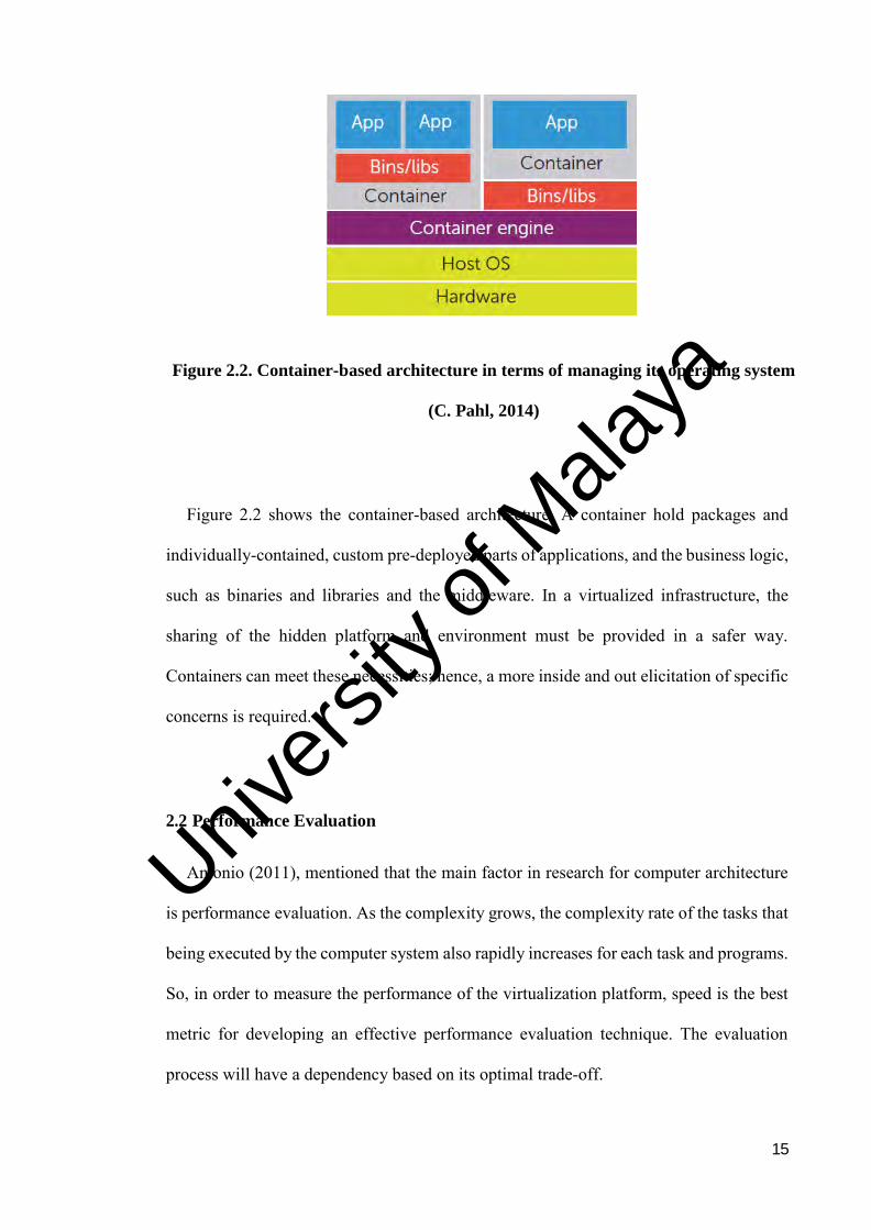
Figure 2.2. Container-based architecture in terms of managing its operating system
(C. Pahl, 2014)
Figure 2.2 shows the container-based architecture. A container hold packages and
individually-contained, custom pre-deployed parts of applications, and the business logic,
such as binaries and libraries and the middleware. In a virtualized infrastructure, the
sharing of the hidden platform and environment must be provided in a safer way.
Containers can meet these necessities; hence, a more inside and out elicitation of specific
concerns is required.
2.2 Performance Evaluation
Antonio (2011), mentioned that the main factor in research for computer architecture
is performance evaluation. As the complexity grows, the complexity rate of the tasks that
being executed by the computer system also rapidly increases for each task and programs.
So, in order to measure the performance of the virtualization platform, speed is the best
metric for developing an effective performance evaluation technique. The evaluation
process will have a dependency based on its optimal trade-off.
Univers
ity of
Mala
ya

16
According to Pahl (2015), the main figure that runs the infrastructure layer is the virtual
machines as it provides a virtualized OS. Container concept is similar as virtual machine
but as it is using a lightweight technology, container will consume less resources and
minimise the execution time. Low-level construct is provided by both virtual machine
and container. Bernstein (2016), mentioned that the developer can navigate the operating
system with an interface as interaction between the developer and the operating system.
However, if the developer wants to deploy application in the Cloud infrastructure, it is
recommended to deploy using container virtualization technology as it will package the
application into the lightweight container.
Figure 2.3. Container image architecture based on namespace and cgroup
extension (Pahl, 2015)
As shown in Figure 2.3, the new Linux dispersions give part components, such as
namespaces and control groups, to separate procedures on a combined operating system,
support through the Linux Container (LXC) project. By separating the namespace will
allow the groups of procedures to be isolated, keeping them from seeing assets in different
Univers
ity of
Mala
ya

17
groups. Container innovations utilize distinctive namespaces for process detachment,
network interfaces, access to network, mount focuses, and for isolating kernel and identify
versions. Control groups oversee and constrain resource from getting through in process
groups through extreme authorisation, accounting and, for instance, by restricting the
memory accessible to a specific container as per said by Amit (2016).
Wang et al., (2017), mentioned that the main challenges of executing critical
application within Cloud environment is the execution must satisfy the deadlines and
response time in virtualization environment. This factor needs to be considered to secure
guaranteed performance of the infrastructure. Therefore, performance evaluation on the
applications is essential to obtain the most effective infrastructure platform for application
deployment.
Based on Wang et al., (2017), different performance levels from the deployment of
task will lead to different virtual machine services, as a result, it will obtain a different
impact on the application cost and quality of services. Different requirements from the
individual application will diverse the quality of services of the Cloud applications.
Although the accuracy of the application is guaranteed, the application failure will lead
to violation of the deadlines. Hence, execution timing for critical application should be
carefully planned and maximise in the Cloud infrastructure. There are many perspectives
that can be used to compare the performance of virtualization mentioned by Kozhirbayev
(2017).
According to Zhanibek (2016), to evaluate container-based technologies from the
perspectives of their overhead, it is crucial to measure the overheads incurred based on
non-virtualized environments. The analysis conducted was focused on a range of
performance criteria: the performance of compute, memory, network bandwidth, latency
and storage overheads. In order to obtain accuracy and consistency in the bunch of results,
Univers
ity of
Mala
ya
18
a lot of experiments were repeated, in which the average timing and standard deviation
were recorded.
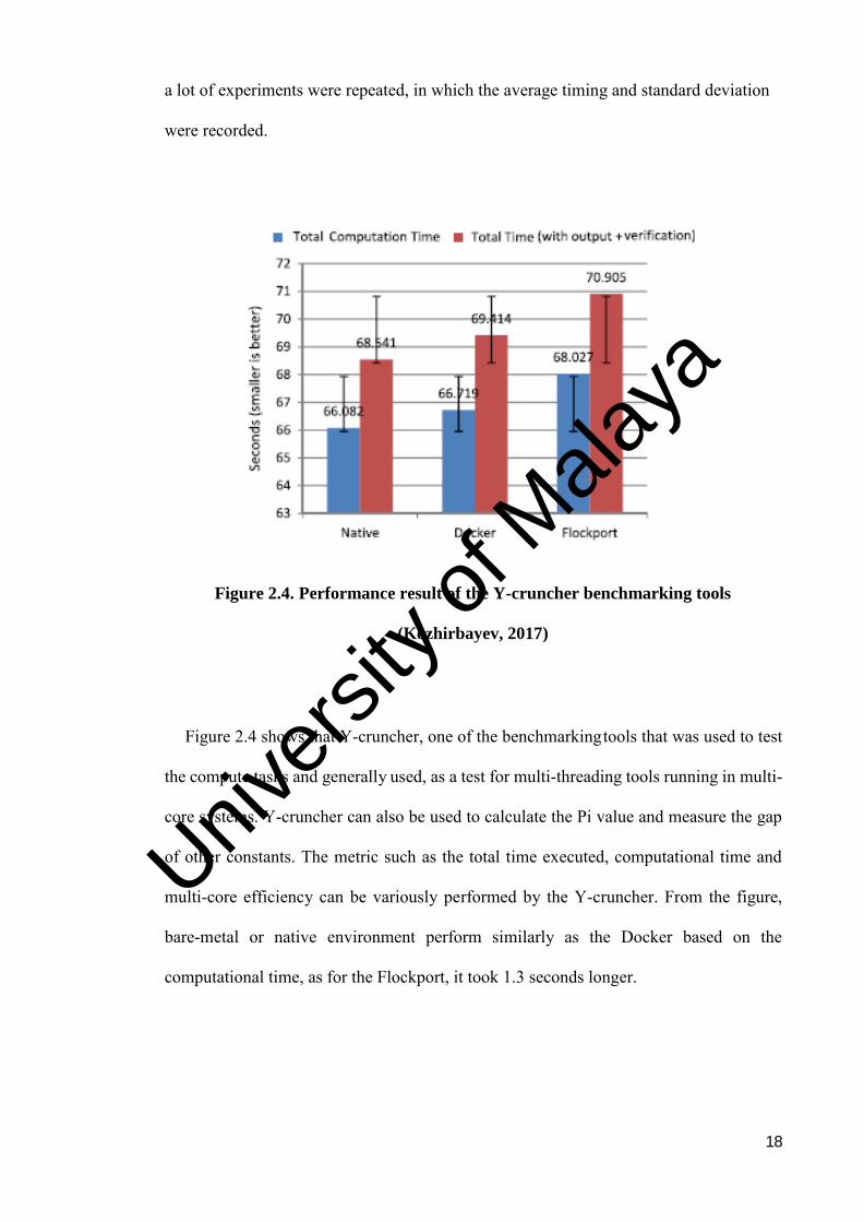
Figure 2.4. Performance result of the Y-cruncher benchmarking tools
(Kozhirbayev, 2017)
Figure 2.4 shows that Y-cruncher, one of the benchmarking tools that was used to test
the compute tasks and generally used, as a test for multi-threading tools running in multi-
core systems. Y-cruncher can also be used to calculate the Pi value and measure the gap
of other constants. The metric such as the total time executed, computational time and
multi-core efficiency can be variously performed by the Y-cruncher. From the figure,
bare-metal or native environment perform similarly as the Docker based on the
computational time, as for the Flockport, it took 1.3 seconds longer.
Univers
ity of
Mala
ya
19
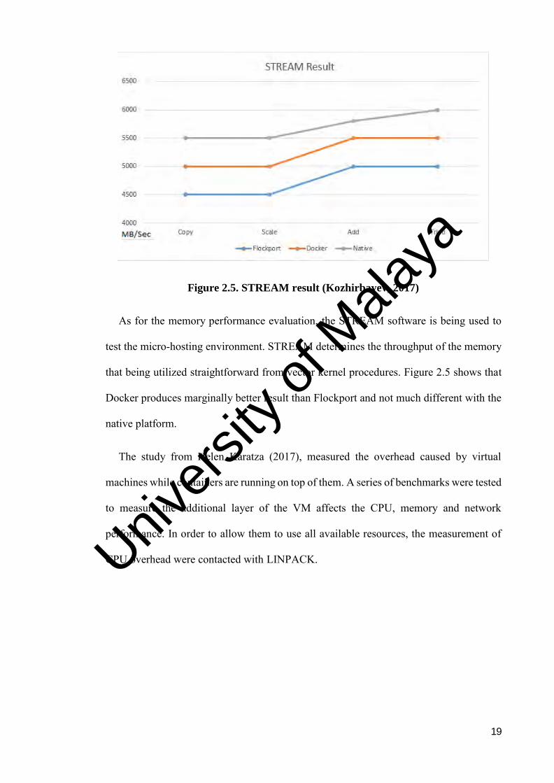
Figure 2.5. STREAM result (Kozhirbayev, 2017)
As for the memory performance evaluation, the STREAM software is being used to
test the micro-hosting environment. STREAM determines the throughput of the memory
that being utilized straightforward from vector kernel procedures. Figure 2.5 shows that
Docker produces marginally better result than Flockport and not much different with the
native platform.
The study from Helen Karatza (2017), measured the overhead caused by virtual
machines while containers are running on top of them. A series of benchmarks were tested
to measure the additional layer of the VM affects the CPU, memory and network
performance. In order to allow them to use all available resources, the measurement of
CPU overhead were contacted with LINPACK. Univers
ity of
Mala
ya
20
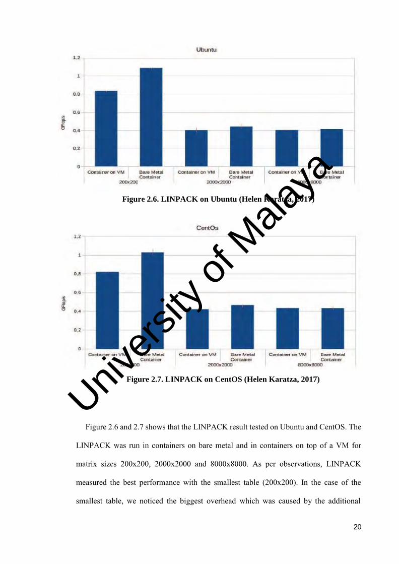
Figure 2.6. LINPACK on Ubuntu (Helen Karatza, 2017)
Figure 2.7. LINPACK on CentOS (Helen Karatza, 2017)
Figure 2.6 and 2.7 shows that the LINPACK result tested on Ubuntu and CentOS. The
LINPACK was run in containers on bare metal and in containers on top of a VM for
matrix sizes 200x200, 2000x2000 and 8000x8000. As per observations, LINPACK
measured the best performance with the smallest table (200x200). In the case of the
smallest table, we noticed the biggest overhead which was caused by the additional
Univers
ity of
Mala
ya
21
virtualization layer of the VM and is about 28.41% in average for the two operating
systems. This happens because VMs hide the nature of system information from the
execution environment. Regarding the bigger tables, we observed a lower performance,
as well as a much smaller gap (0.87 % in average for the two operating system) between
the container on bare metal and the container on top of the VM. This probably happens
because the necessary data cannot be cached in the available high speed memory which
as a result increases the overhead.
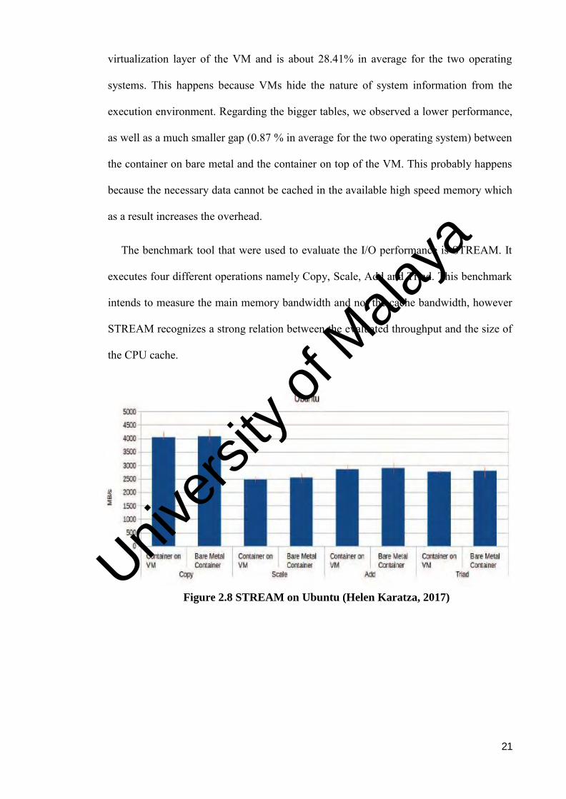
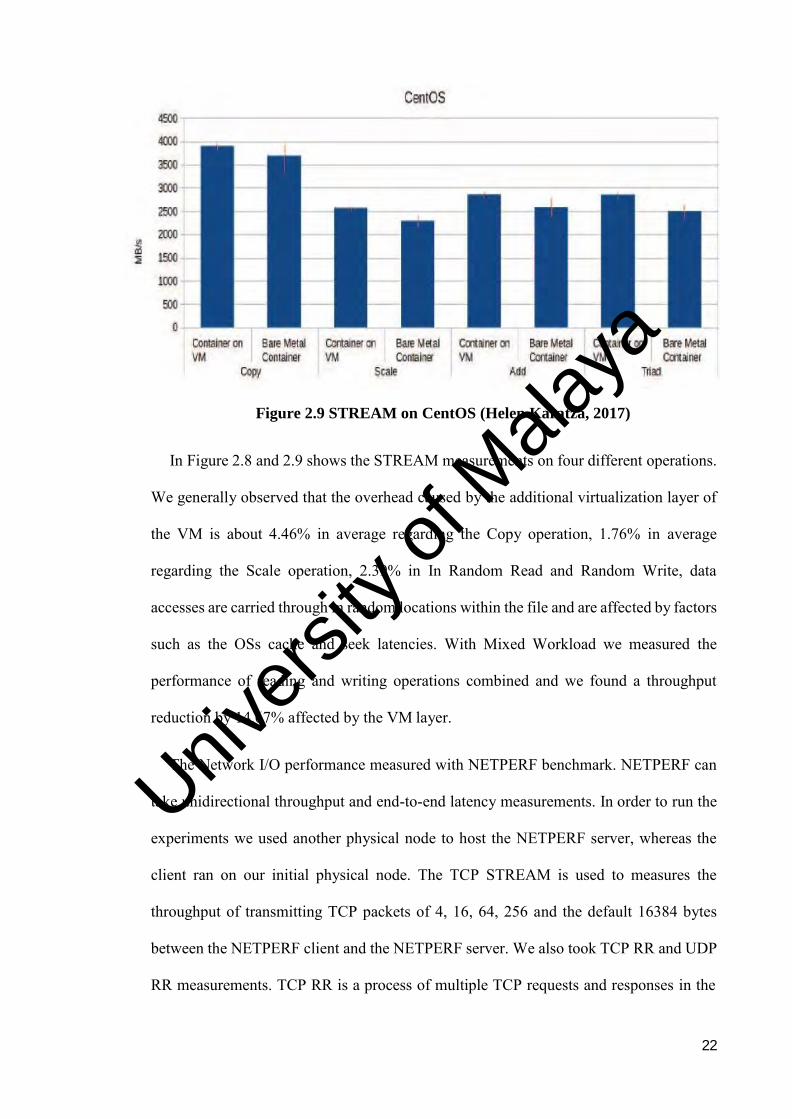
The benchmark tool that were used to evaluate the I/O performance is STREAM. It
executes four different operations namely Copy, Scale, Add and Triad. This benchmark
intends to measure the main memory bandwidth and not the cache bandwidth, however
STREAM recognizes a strong relation between the evaluated throughput and the size of
the CPU cache.
Figure 2.8 STREAM on Ubuntu (Helen Karatza, 2017) Univ
ersity
of M
alaya
22
Figure 2.9 STREAM on CentOS (Helen Karatza, 2017)
In Figure 2.8 and 2.9 shows the STREAM measurements on four different operations.
We generally observed that the overhead caused by the additional virtualization layer of
the VM is about 4.46% in average regarding the Copy operation, 1.76% in average
regarding the Scale operation, 2.39% in In Random Read and Random Write, data
accesses are carried through in random locations within the file and are affected by factors
such as the OSs cache and seek latencies. With Mixed Workload we measured the
performance of reading and writing operations combined and we found a throughput
reduction by 14.67% affected by the VM layer.
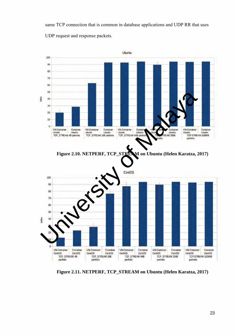
The Network I/O performance measured with NETPERF benchmark. NETPERF can
take unidirectional throughput and end-to-end latency measurements. In order to run the
experiments we used another physical node to host the NETPERF server, whereas the
client ran on our initial physical node. The TCP STREAM is used to measures the
throughput of transmitting TCP packets of 4, 16, 64, 256 and the default 16384 bytes
between the NETPERF client and the NETPERF server. We also took TCP RR and UDP
RR measurements. TCP RR is a process of multiple TCP requests and responses in the
Univers
ity of
Mala
ya
23
same TCP connection that is common in database applications and UDP RR that uses
UDP request and response packets.
Figure 2.10. NETPERF, TCP_STREAM on Ubuntu (Helen Karatza, 2017)
Figure 2.11. NETPERF, TCP_STREAM on Ubuntu (Helen Karatza, 2017)
Univers
ity of
Mala
ya
24
Figure 2.10 and 2.11 present the TCP STREAM measurements for the default and 5
different packet sizes for the. The two operating systems running on bare metal and on
top of a VM. In all cases we observe that, regarding the smaller packet sizes, the overhead
that the additional layer of VM virtualization causes to the network is significantly higher
compared to the larger packets’ overhead. This is quite reasonable because of the smaller
packets require more computation power. For the small 4 bytes packets there is a mean
throughput reduction by 33.3% in both operating systems, whereas, regarding the bigger
size of 16384 bytes (default packet size) there is a mean throughput reduction by only
0.69% in both operating system when containers run on top of VM.
2.2.1 Performance Evaluation Tools
There are some tools that are used to measure the performance effectiveness between
virtual machines and Docker containers. These tools were specifically designed to
perform different kinds of test, such as compute, memory and I/O.
2.2.1.1 Bonnie++
Bonnie++ is a performance tool that allows the benchmarking of how the filesystems
perform numerous tasks, that makes it a valuable tool once changes are made to the RAID,
how the filesystems are created, and how the network filesystems perform. Bonnie++
benchmarks three things, which are data searching and write speed, range of seeks that
may be performed per second, and range of file metadata operations that are able to be
performed per second. Metadata operations contain file creation and deletion as well as
obtaining metadata, like the file size or owner. As the test is performed, Bonnie++ prints
a line, informing that the test is executed. The Bonnie++ distribution also includes the
Univers
ity of
Mala
ya
25
html page to display all results. It will generate a table for the output after performing the
test.
2.2.1.2 SysBench
SysBench is a standard, cross-platform and multi-threaded benchmark tool for
evaluating OS parameters that are vital for a system running an information beneath
intensive load. SysBench is a benchmark suite which gives a quick impression about the
system performance. The idea of this benchmark suite is to quickly get an impact
concerning about system performance while not setting up advance database benchmarks.
The design is extremely easy. SysBench runs a given range of threads, within which all
execute requests in parallel. The workload created by requests depends on the required
pilot mode. Either the whole range of requests or total time for the benchmark are often
restricted, or both. Obtainable test modes are implemented by compiled-in modules, and
SysBench was designed to simplify the addition of new test modes. Each test mode might
have additional (or workload-specific) choices.
Table 2.2 shows the types of performance evaluation test that can be performed and
the output that is obtained from the test. As stated, there are four types of performance
evaluation test and each of the test will collect different kinds of output and result.
2.2.1.3 Y-Cruncher
Y-cruncher is a program that can compute Pi and other constants to trillions of digits.
It is the first of its kind that is multi-threaded and scalable to multi-core systems. Ever
since its launch in 2009, it has become a common benchmarking and stress-testing
application for overclock and hardware enthusiasts.
The main computational features of y-cruncher are:
Univers
ity of
Mala
ya
26
Able to compute Pi and other constants to trillions of digits.
Two algorithms are available for most constants. One for computation and one
for verification.
Multi-Threaded - Multi-threading can be used to fully utilize modern multi-
core processors without significantly increasing memory usage.
Vectorized - Able to fully utilize the SIMD capabilities for most processors.
Swap Space - management for large computations that require more memory
than there is available.
Multi-Hard Drive - Multiple hard drives can be used for faster disk swapping.
Semi-Fault Tolerant - Able to detect and correct for minor errors that may be
caused by hardware instability or software bugs.
2.2.1.4 STREAM Benchmarking Tools
The STREAM benchmark is a simple synthetic benchmark program that measures
sustainable memory bandwidth (in MB/s) and the corresponding computation rate for
simple vector kernels. It is specifically designed to work with datasets much larger than
the available cache on any given system, so that the results are more indicative of the
performance of very large, vector style applications.
For this research, instead of using STREAM and Y-cruncher, Sysbench and Bonnie++
will be selected as the performance evaluation tools. This is because, for I/O testing,
custom file size is allowed by Sysbench. Hence, evaluation testing will be more
comprehensive and accurate. As for STREAM, during the evaluation test, the total
number of threads cannot be defined initially. Furthermore, the STREAM output did not
Univers
ity of
Mala
ya
27
show the statistic of minimum, average and maximum output per-request. Sysbench on
the other hand, the result shows all the mentioned with clear and informative way.
Compared from Bonnie++, Y-cruncher is also multi-threaded program, but it is
deterministic. It was designed to avoid problem that common occurs in asynchronous
application and can be extremely difficult to track down and fix. Because of this
determinism, testing crashes and errors happen intermittently. Bonnie++ is very flexible
as the file size can be set from 1GB onwards. The output provided also were split into 2
portion which is the command output and the HTML table output. There is also
information regarding how many I/O blocks transferred per second. That is the reason
Bonniee++ and Sysbench is being used for this research.
Table 2.2. Main purpose of performance evaluation test
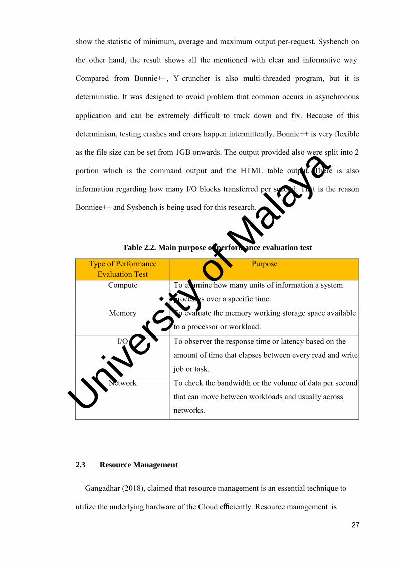
Type of Performance Evaluation Test
Purpose
Compute To examine how many units of information a system
processes over a specific time.
Memory To evaluate the memory working storage space available
to a processor or workload.
I/O To observer the response time or latency based on the
amount of time that elapses between every read and write
job or task.
Network To check the bandwidth or the volume of data per second
that can move between workloads and usually across
networks.
2.3 Resource Management
Gangadhar (2018), claimed that resource management is an essential technique to
utilize the underlying hardware of the Cloud efficiently. Resource management is
Univers
ity of
Mala
ya
28
important in virtualized infrastructure as it gives a clear picture on the amount of task and
job that must be done and helps to schedule and plan the task executions by allocating
suitable resources for every task and job. Resource management provides an efficient and
effective deployment of a job and task with a satisfying result. The purpose of resource
management is to manage the scheduling task for all the jobs before they are executed.
This portion involves allocating resources into the job.
According to Linthicum (2016), the goal of managing the application-tier and
deploying application designs most likely can be achieved by containers. On the operating
system level, container can manage the applications such as Web servers, database servers
and application servers. Furthermore, the hypervisor-based platform is focusing to
separate and hold the resources based on machine-by-machine. As for containers, the
CPU resources can be shared and distributed than VMs.
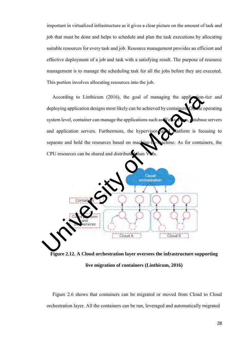
Figure 2.12. A Cloud orchestration layer oversees the infrastructure supporting
live migration of containers (Linthicum, 2016)
Figure 2.6 shows that containers can be migrated or moved from Cloud to Cloud
orchestration layer. All the containers can be run, leveraged and automatically migrated
Univers
ity of
Mala
ya
29
from one Cloud to another, to support the infrastructure requirements. Computing
capabilities can be distributed since the applications can be separated into various kind of
domains.
Non-stop monitoring of resources is vital in managing the virtual environment
mentioned by Pooja & Pandey (2014). To guarantee the Service Level Agreement (SLA)
while optimally consuming the resources, performance evaluation needs to be considered
in order to maximise the utilization of the compute system. As a result, different users
can share the same single multicore node claimed by Miguel et al., (2013). The best
virtualization that can increase the percentage of resource sharing is the container-based
virtualization by allowing multiple separated instances of user-space. Meanwhile, the
disadvantage of container-based virtualization is it cannot firmly isolate the resource as
good as the hypervisor-based virtualization.
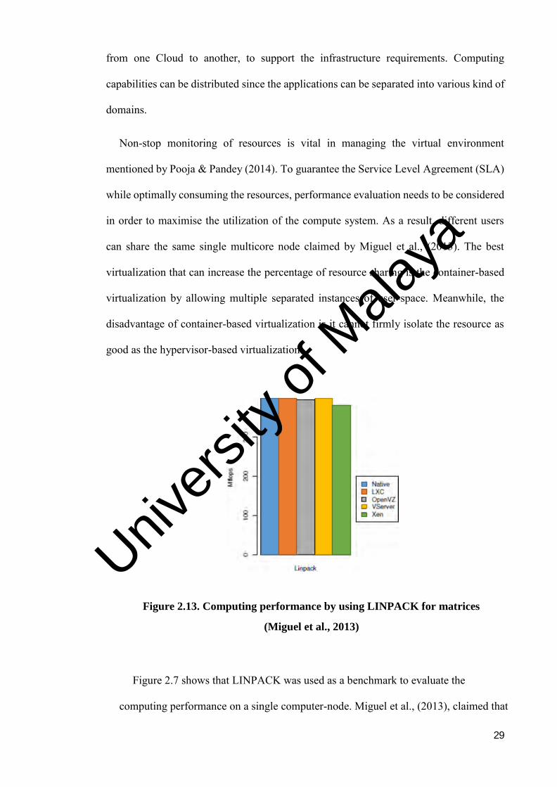
Figure 2.13. Computing performance by using LINPACK for matrices
(Miguel et al., 2013)
Figure 2.7 shows that LINPACK was used as a benchmark to evaluate the
computing performance on a single computer-node. Miguel et al., (2013), claimed that
Univers
ity of
Mala
ya
30
LINPACK consists of a set of subroutines that analyses and solves linear equations by
the least square’s method. Result of the LINPACK can be used to estimate
performance and it is run over a single processor. LINPACK is used as a tools to
measure the matrices of order 300 in all container-based systems and compare them
with Xen. The first one is Linux-VServer, this system is one of the oldest
implementations of Linux container-based system. Instead of using namespaces,
Linux-VServer introduced its own capabilities in the Linux kernel, such as process
isolation, network isolation and CPU isolation. This system also does not virtualize
network subsystem as all the networking subsystem within all containers share the
same routing and tables IP. The second system is the OpenVZ. This system offers
similar functionality to Linux-VServer. However, it is built on top of kernel
namespaces, making sure that every container has its own isolated subset of a resource.
Moreover, the OpenVZ uses the network namespace. In this way, each container has
its own network stack, which includes network devices, routing tables, firewall and so
on. The third system is the LXC. In the same way as OpenVZ, LXC uses kernel
namespaces to provide resource isolation among all containers. Furthermore, unlike
the OpenVZ and Linux-VServer, the LXC only allowed resource management via
cgroups. Thus, LXC uses cgroups to define the configuration of network namespaces.
As for Xen system, it will be use as the representative of hypervisor-based
virtualization, because it is considered one of the most mature and efficient
implementations of this kind of virtualization. As the result, there was not much
difference obtained from the experiment as all the container-based systems obtained
similar result to the native, as shown in Figure 2.7. It is due to the fact that there was
no influence of the different compute schedulers when a single compute -intensive
process is run on a single processor.
Univers
ity of
Mala
ya

31
Figure 2.14. Memory throughput by using STREAM (Miguel et al., 2013)
As shown in Figure 2.8, the memory performance evaluation is evaluated with
STREAM, a simple artificial benchmark program that measures the properties of memory
bandwidth. This performance evaluation tool will perform four types of vector operations,
which is copy, add, scale and triad, and uses a larger dataset than the cache memory
available in the infrastructure. As observed, the result was similar as native system for
container-based due to the unutilized memory of the host, enabling a better use of
memory. Unfortunately, the worst result was in Xen, which presented an average
overhead of approximately 31% as compared to the native throughput. The hypervisor-
based virtualization layer implements the translation of memory accesses that causing the
memory to be overheaded and resulting a decrease in terms of performance.
Univers
ity of
Mala
ya
32
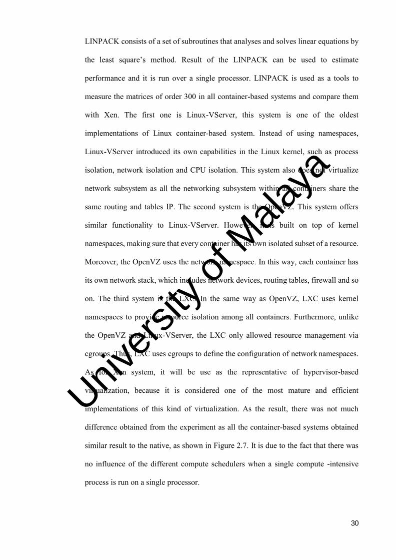
Figure 2.15. Disk throughput by using IOZone (Miguel et al., 2013)
Figure 2.9 shows the result of disk performance evaluation by using IOZone
benchmark tool. The IOZone can generate, access pattern and measure a variety of file
operations. A record size of 10GB and 4KB will be run as a test case. According to graph,
it revealed that both Linux-VServer and LXC had a similar result for read and re-read
operations. Furthermore, a gain of performance was achieved as compared to the OpenVZ
results which is lower than both Linux-VServer and LXC. The root cause probably was
due to the I/O scheduler was being used by the different systems. The worst result was
obtained in Xen for all I/O operations as caused by the para-virtualized drivers. These
drivers weren’t ready to attain a high performance nevertheless.
Furthermore, in an observation-based study by Jeroen (2014), the basic principle of a
container was that it allowed for processes and their resources to be isolated without
hardware separation or hardware dependencies. Containers provide a form of
virtualization platform that each container will run their own OS sharing the kernel.
From the above findings, it is very important to conduct a performance evaluation on
different approaches of virtualization. The performance results can help both researchers
Univers
ity of
Mala
ya
33
and practitioners to design better virtualization architecture according to application
needs. The study can be viewed as a foundation for more sophisticated evaluation in the
future.
2.4 Docker-Sec Automation Architecture
Docker-sec is an open-source, automated and user-friendly mechanism for securing
Docker and generally OCI2 compatible containers. Docker-sec offers users the ability to
automatically generate initial container profiles based on configuration parameters
provided during container initialization. If a stricter security policy is required, Docker-
sec can dynamically enhance the initial profile with rules extracted through the monitoring
of real-time container execution. Docker-sec adds an additional security layer on top of
Docker’s security defaults by automatically creating each container AppArmor profiles
claimed by Fotis Loukidis (2018).
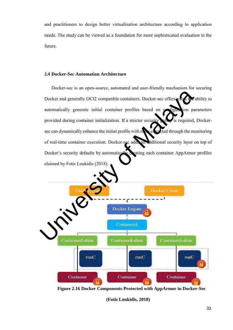
Figure 2.16 Docker Components Protected with AppArmor in Docker-Sec
(Fotis Loukidis, 2018)
Univers
ity of
Mala
ya

34
Figure 2.10 Show how the architecture of Docker component with AppArmor.
Docker-sec creates secure AppArmor profiles for all Docker components for rendering
the environment. Container profiles are created automatically using rules extracted from
the configuration of each container and enhanced with rules based on the behaviour of the
contained application. To that end, Docker-sec employs two mechanisms which is static
analysis, which creates initial profiles from static Docker execution parameters and
dynamic monitoring which enhances them through monitoring the container workflow
during a user-defined testing period. The goal is to construct a separate profile per
container, placing each one in a separate security context in order to restrict the sharing of
resources among containers. The components of Docker that are automatically protected
via AppArmor profiles via Docker-sec are designated with red lock logos.
2.5 Workflow
Single or multiple computational task can be easily expressed by users using the
scientific workflow. This computational tasks include reformatting the data, running an
analysis from an instrument or a database. The dependencies of the task in most cases can
be described by scientific workflow as a directed acyclic graph (DAG), where the edges
denote the task dependencies and the nodes are tasks. Scientific workflow is very efficient
is managing the data flow. Everything from very large parallel task to short serial task
surrounded by small, serial tasks used for pre- and post-processing as mentioned by
Pegasus (2013).
Univers
ity of
Mala
ya

35
According to Paul Martin et al., (2016), a common strategy to make the simulation
experiments more manageable is to model them as workflows and use a workflow
management system to organise the execution. The automation process of the business in
which task, documents or information are passed from one participant to another can be
defined as a workflow, based on the set of its procedural rules said by O’ Brien (2010).
Figure 2.17. Common workflow in scientific experiments (Martin et al., 2016)
As shown in Figure 2.10, a workflow was split into three components. The first one
would be a list of operations or tasks, the second is a group of dependencies between all
the internal connected tasks and finally the group resources that contains data is used to
execute or remove the flow. Basically, from the figure above, the vertices are the data and
tasks resources. The edges dependent on the connection of the vertices. The edges can
represent two kinds of dependency, which are the control flow and data flow. Control
flow graphs involve task and priority requirements. The data-flow depends on the
conditions of the undertakings flow of data. The data move along into a circular segment
and are changed by the pre-process operator. Every data item will be changed by the pre-
process operator and the result will be transmitted to succeeding operator. The graph of
the data-flow allow the operators to execute to cover in a prepared pipeline.
Univers
ity of
Mala
ya
36
2.5.1 Workflow Orchestration
This workflow orchestration will separate the tasks based on their intensiveness. The
intensiveness falls into 3 categories, which is compute, memory and I/O intensive. This
orchestration will arrange the task in sequence and manage the task before it is scheduled.
2.5.2 Workflow Scheduling
Workflow scheduling schedules the task to be deployed on the respective platform.
This scheduling will be decided based on the workflow intensiveness and different
category will be deployed in a different platform in order to receive the fastest deployment
and response time.
2.5.3 Workflow Deployment
After all tasks were sorted in sequence and scheduled, the deployment is where the
task will be executed into the platform. The task will be executed in hypervisor-based or
container-based virtualization platform. Table 2.3 shows the literature summary.
Table 2.3. Summary of Literature review
Author Year Analysis Summary
Claus Pahl 2014 Understanding the concept
of virtual machines and
container in virtualization
technologies are important
to have a clear view of what
is needed to be evaluate.
Virtual machines (VMs) are the
backbone of the infrastructure
layer, providing virtualized
operating systems (OSs).
Containers are similar but have a
more lightweight virtualization
Univers
ity of
Mala
ya
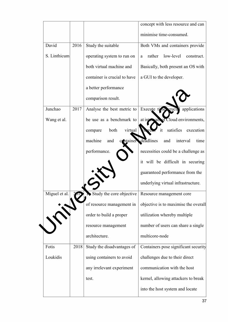
37
concept with less resource and can
minimise time-consumed.
David
S. Linthicum
2016 Study the suitable
operating system to run on
both virtual machine and
container is crucial to have
a better performance
comparison result.
Both VMs and containers provide
a rather low-level construct.
Basically, both present an OS with
a GUI to the developer.
Junchao
Wang et al.
2017 Analyse the best metric to
be use as a benchmark to
compare both virtual
machine and container
performance.
Execute time crucial applications
at intervals of Cloud environments,
whereas it satisfies execution
deadlines and interval time
necessities could be a challenge as
it will be difficult in securing
guaranteed performance from the
underlying virtual infrastructure.
Miguel et al. 2013 To Study the core objective
of resource management in
order to build a proper
resource management
architecture.
Resource management core
objective is to maximise the overall
utilization whereby multiple
number of users can share a single
multicore-node
Fotis
Loukidis
2018 Study the disadvantages of
using containers to avoid
any irrelevant experiment
test.
Containers pose significant security
challenges due to their direct
communication with the host
kernel, allowing attackers to break
into the host system and locate
Univers
ity of
Mala
ya
38
containers more easily than virtual
machines.
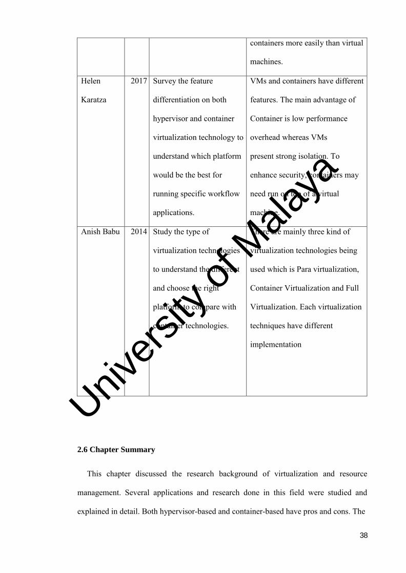
Helen
Karatza
2017 Survey the feature
differentiation on both
hypervisor and container
virtualization technology to
understand which platform
would be the best for
running specific workflow
applications.
VMs and containers have different
features. The main advantage of
Container is low performance
overhead whereas VMs
present strong isolation. To
enhance security, containers may
need run on top of a virtual
machine.
Anish Babu 2014 Study the type of
virtualization technologies
to understand the different
and choose the right
platform to compare with
container technologies.
There are mainly three kind of
virtualization technologies being
used which is Para virtualization,
Container Virtualization and Full
Virtualization. Each virtualization
techniques have different
implementation
2.6 Chapter Summary
This chapter discussed the research background of virtualization and resource
management. Several applications and research done in this field were studied and
explained in detail. Both hypervisor-based and container-based have pros and cons. The
Univers
ity of
Mala
ya
39
problem of the existing hypervisor and container virtualization technology were
identified.
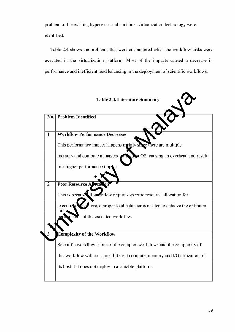
Table 2.4 shows the problems that were encountered when the workflow tasks were
executed in the virtualization platform. Most of the impacts caused a decrease in
performance and inefficient load balancing in the deployment of scientific workflows.
Table 2.4. Literature Summary
No. Problem Identified
1 Workflow Performance Decreases
This performance impact happens mainly since there are multiple
memory and compute managers for a guest OS, causing an overhead and result
in a higher performance impact.
2 Poor Resource Allocation
This is because all workflow requires specific resource allocation for
execution. Therefore, a proper load balancer is needed to achieve the optimum
performance of the executed workflow.
3 Complexity of the Workflow
Scientific workflow is one of the complex workflows and the complexity of
this workflow will consume different compute, memory and I/O utilization of
its host if it does not deploy in a suitable platform.
Univers
ity of
Mala
ya

40
To address the problems, an automate system architecture technique was proposed.
The methodology adopted for this research work will be discussed in the next chapter.
Univers
ity of
Mala
ya
41
CHAPTER 3: METHODOLOGY
This chapter discusses the research techniques used in the dissertation. The chapter
starts with a discussion about the research methods then, the research phases, such as
information gathering and analysis, proposed method, system design and implementation,
system evaluation and documentation are discussed. A summary is provided at the end of
chapter.
3.1 DoKnowMe
DoKnowMe is a software engineering methodology that can be used to evaluate
performance and has become one of the main factors in software quality assurance.
According to (Li & O’Brien, 2016), DoKnowMe was employed to guide the study
evaluation implementations. DoKnowMe is a part of evaluation methodology on the
analogy of “class” in object-oriented programming. Driven by the concept of object-
oriented programming, the general performance evaluation logic was distinguished, and
an abstract evaluation methodology was developed into the term “Domain Knowledge-
driven Methodology (DoKnowMe)”. As the predefined domain-specific knowledge were
remained, DoKnowMe can be summarised into more specified methodologies to help
evaluate the computing system and different software performance. There are four factor
that is a generic validation which is repeatability, usefulness, feasibility and effectiveness.
All factors were used to validate the methodology in the evaluation domain. With good
and promising evaluation results, more evaluation strategies can be integrated to improve
DoKnowMe, and hence become more specific on the performance evaluation of
virtualization technologies.
Univers
ity of
Mala
ya
42
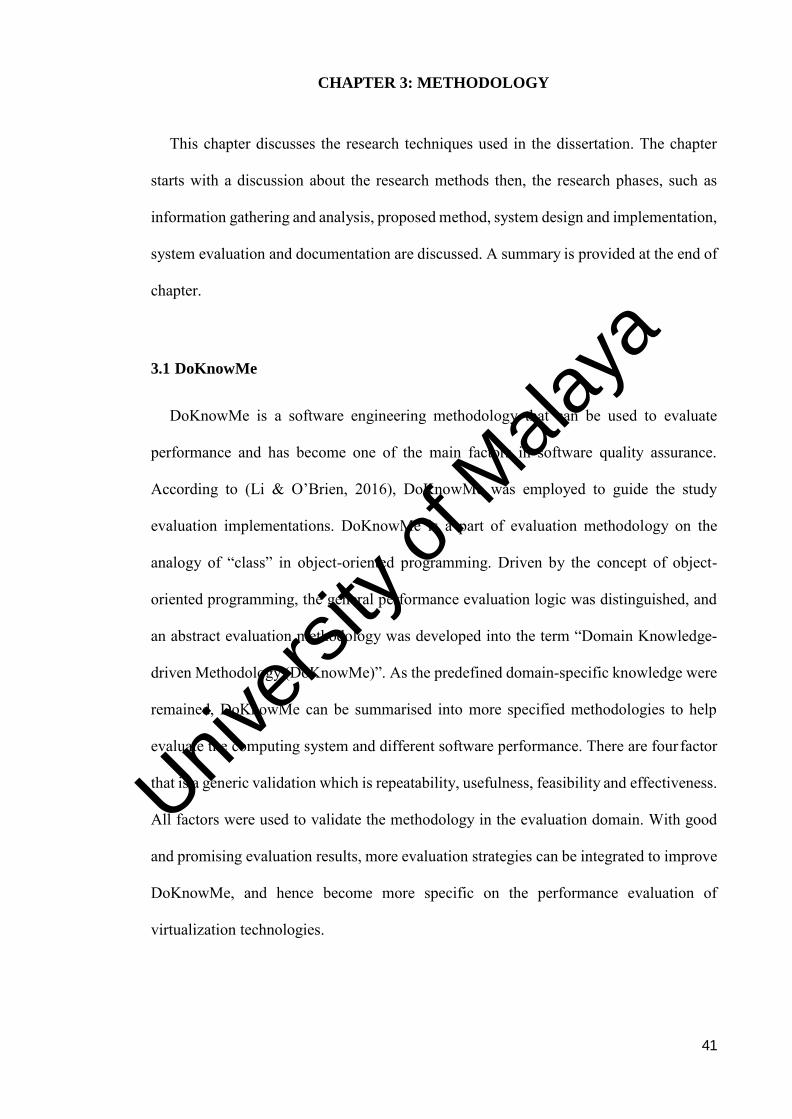
Figure 3.1. The relationship between DoKnowMe and its instance methodologies
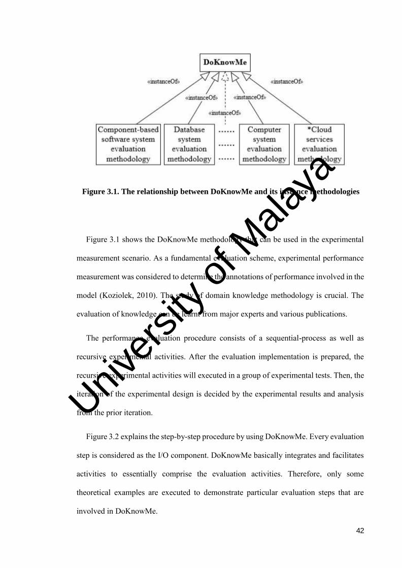
Figure 3.1 shows the DoKnowMe methodology that can be used in the experimental
measurement scenario. As a fundamental evaluation scheme, experimental performance
measurement was considered to determine the annotations of performance involved in the
model (Koziolek, 2010). The study of domain knowledge methodology is crucial. The
evaluation of knowledge can be learnt from major experts and various publications.
The performance evaluation procedure consists of a sequential-process as well as
recursive experimental activities. After the evaluation implementation is prepared, the
recursive experimental activities will executed in a group of experimental tests. Then, the
iteration of the experimental design is decided by the experimental results and analysis
from the prior iteration.
Figure 3.2 explains the step-by-step procedure by using DoKnowMe. Every evaluation
step is considered as the I/O component. DoKnowMe basically integrates and facilitates
activities to essentially comprise the evaluation activities. Therefore, only some
theoretical examples are executed to demonstrate particular evaluation steps that are
involved in DoKnowMe.
Univers
ity of
Mala
ya
43
Figure 3.2. The step-by-step procedure by using DoKnowMe
Univers
ity of
Mala
ya
44
Figure 3.2 shows the sequential procedure of DoKnowMe. All procedures involved in
the methodology are considered on “what”, “how”, “why”, “when” and “where” the
experiment tests should occur. Each procedure has its own dependencies and all
procedures must be in sequence so that the objective of the experiment can be achieved.
3.1.1 Requirement Recognition
The recognition of a requirement is not only to understand a problem related to the
system performance evaluation, but also to realize a transparent statement of the analysis
purpose, which must be clear with a non-trivial task. A clearly nominative evaluation
requirement will facilitate correct driving of the remaining steps within the evaluation
implementation. To solve performance evaluation, the evaluation requirement will be
identified based on the research problem statements. The problem statements will find an
idea on how to measure the performance effectiveness in both virtualization platforms
(Zheng, 2016).
3.1.2 Performance Feature Identification
Given the clarified evaluation requirement of a system, evaluators need to further
identify relevant performance features to be evaluated. Since different end users could be
running different kind of application in the virtualization platform, it would be difficult
for evaluators to directly locate proper performance features. Therefore, it will be helpful
and valuable to measure the performance based on applications that runs on hypervisor-
based or container-based virtualization platform.
Univers
ity of
Mala
ya
45
3.1.3 Metrics and Benchmarks Listing
The choice of the right metrics depends on the identified performance features to be
evaluated, while given that the performance features are yet insufficient for choosing right
metrics. On the one hand, a performance feature can be measured by different metrics
with different benchmarks. Therefore the performance metric that can be used to evaluate
the performance is CPU, network, I/O and memory.
3.1.4 Metrics and Benchmarks Selection
A metric is a measurable quantity that precisely captures some characteristics of a
performance feature. The selection of metrics plays an essential role in evaluation
implementations. Hence, the metric that really effective to measure the performance of
the virtualization platform is CPU, memory and I/O. So this three metric will be the
benchmark of the performance evaluation.
3.1.5 Experimental Factor Listings
Although listing a whole scope of experimental factors may not be simply achieved,
the factor listings should be kept as comprehensive as possible continually. This is often
for more analysis and decision-making regarding the factor choices and information
collected. Therefore, the aim of experimental factors listing is to list all experimental
factors associated with performance features that are to be evaluated. In the present study,
the compute, memory and I/O are used as the experimental metric. Hence, there are set
of performance evaluation tools that we can chose to run the performance evaluation
experiment such as Sysbench, STREAM, Y-cruncher and Bonnie++.
Univers
ity of
Mala
ya
46
3.1.6 Experimental Factors Selection
There is no conflict between selecting limited factors in this step and keeping a
comprehensive factor list in the previous step. On the one hand, an evaluation requirement
usually comprises a set of experiments, and different experiments might have to select
different factors from the same factor list. Hence, Bonnie++ and Sysbench is being chose
as the performance evaluation tools to measure the CPU, memory and I/O intensiveness
within the hypervisor-based and container-based virtualization technology.
3.1.7 Experimental Design
Once the experimental factors are selected, the evaluation experiments are ready and
designed. Normally, a low scale of pilot experiment would profit the relevant
experimental design, by serving evaluators to urge conversant in the experimental
environment and optimize the experimental sequence. The experiment design involves
the way the experiment should be conducted. The experiment will be performed in a
workflow design. So basically, there are 4 sets of workflows that will be use in the
experiment test. The first one is the CPU intensive workflow which the workflow will
consist a lot of task that requires CPU. The second set would be the memory intensive
workflow. The memory intensive workflow will also have a lot of task that requires
memory from its host. The third set is the I/O intensive workflow. This set of workflow
will have a lot of input and output task will requires its host to allocate more resources.
The last set is the uniform workflow. This workflow will consist of CPU, memory and
I/O task.
Univers
ity of
Mala
ya

47
3.1.8 Experimental Implementation
Implementing an experiment involves carrying out a series of experimental actions,
starting from the experimental environment preparation to running benchmarks.
Generally, experimental results might answer their corresponding evaluation requirement
queries. However, in most cases, a lot of convincing conclusions are drawn through
further experimental analysis. So for the performance evaluation test, there a 4 sets of
workflow experiment is conducted. All results are recorded and analysed during the
implementation of the test cases to see if there is any difference in response time and
application responsiveness in both hypervisor and container-based virtualization
platforms.
3.1.9 Experimental Analysis
Experimental results can sometimes answer their corresponding evaluation
requirement questions already. However, in most cases, more convincing conclusions
would have to be drawn through further experimental analysis. So based from the test that
were conducted, a statistic diagram is formed to ease to draw the conclusion and potential
decision-making process.
3.1.10 Conclusion and Documentation
DoKnowMe uses a structured manner to implement conclusion and documentation.
Tables and visual representations of experimental analysis results are used to interact to
the pre-specified requirement queries. The answers to all requirement queries are
summarised into linguistic communication findings to mirror the conclusions higher.
Univers
ity of
Mala
ya

48
Based on the results obtained from the experiment test, we can have a better conclusion
from the report.
3.2 Chapter Summary
The DoKnowMe research methodology plays some key roles in evaluating
performance of the virtualization technology. An automated system architecture is
proposed in this research to assess and measure both virtualization platform and deploy
application in the suitable platform. The next chapter elaborates the system design,
architecture, implementation and testing phases.
Univers
ity of
Mala
ya
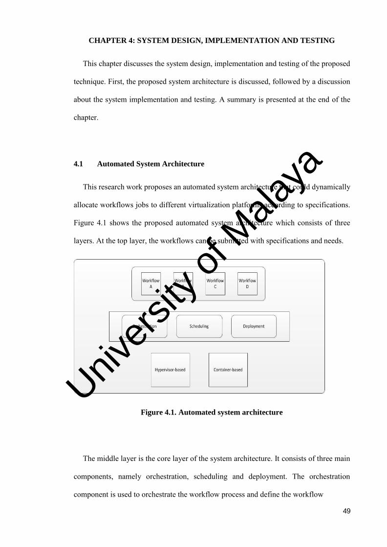
49
CHAPTER 4: SYSTEM DESIGN, IMPLEMENTATION AND TESTING
This chapter discusses the system design, implementation and testing of the proposed
technique. First, the proposed system architecture is discussed, followed by a discussion
about the system implementation and testing. A summary is presented at the end of the
chapter.
4.1 Automated System Architecture
This research work proposes an automated system architecture that could dynamically
allocate workflows jobs to different virtualization platforms according to specifications.
Figure 4.1 shows the proposed automated system architecture which consists of three
layers. At the top layer, the workflows can be submitted with specifications and needs.
Figure 4.1. Automated system architecture
The middle layer is the core layer of the system architecture. It consists of three main
components, namely orchestration, scheduling and deployment. The orchestration
component is used to orchestrate the workflow process and define the workflow
Univers
ity of
Mala
ya
50
specifications. This component defines all jobs in the workflow together with their
relations. Besides, each job parameters are stated in addition to the specifications. This
information is essential for scheduling components. Scheduling is the second core
component in the middle layer. Scheduling plays a vital role in terms of allocating the
resources to the jobs in each workflow. The objective of scheduling function is to
minimise the total execution time for each workflow.
The last core component is deployment. Deployment handles all workflows before
they are deployed to the platform. In the hypervisor-based platform, deployment
provisions the virtual machine and configures the virtual machine specifications based on
workflow criteria. Meanwhile in container-based platform, deployment handles all the
container creations and install all dependencies for the workflow application to run in
those containers. Each container will extract library and bin files and provision an image
for it.
The bottom layer consists of two types of virtualization platforms, namely hypervisor
and container. The system will deploy the workflow application to the selected
virtualization platform and return the output once the execution is completed. The
virtualization platform is set up automatically based on workflow needs.
Figure 4.2 shows the interaction of the core components in the proposed system
architecture. The applications are categorised into 3 categories, namely compute
intensive, memory intensive, and I/O intensive. The workflow needs can be specified
based on the above categories.
Univers
ity of
Mala
ya
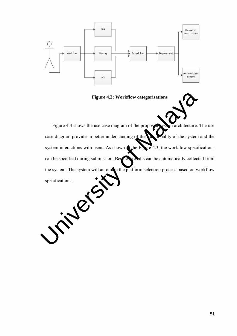
51
Figure 4.2: Workflow categorisations
Figure 4.3 shows the use case diagram of the proposed system architecture. The use
case diagram provides a better understanding of the functionality of the system and the
system interactions with users. As shown in the Figure 4.3, the workflow specifications
can be specified during submission. Besides, results can be automatically collected from
the system. The system will automate the platform selection process based on workflow
specifications.
Univers
ity of
Mala
ya
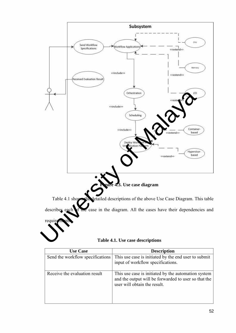
52
Figure 4.3. Use case diagram
Table 4.1 shows the detailed descriptions of the above Use Case Diagram. This table
describes each of the case in the diagram. All the cases have their dependencies and
requirements.
Table 4.1. Use case descriptions
Use Case Description
Send the workflow specifications This use case is initiated by the end user to submit input of workflow specifications.
Receive the evaluation result This use case is initiated by the automation system and the output will be forwarded to user so that the user will obtain the result.
Univers
ity of
Mala
ya

53
Main flow of events: 1. The user sends the request and waits for the automation system decision 2. The system will evaluate the result and map it to the resource
Deploy workflow applications in suitable platform
This use case is when the workflow is already scheduled and orchestrated.
Main flow of events: 1. System will receive scheduling result in sequence 2. System will deploy workflow based on the scheduler decision.
Workflow Applications This use case is initiated by the automated system after the input was received from the user.
Main flow of events: 1. The system will wait for the input from the user. 2. Automation system will orchestrate the workflow specifications based on user input 3. The system will schedule the workflow based on their priority. 4. After scheduling task completed, system will deploy workflow in the suitable platform. 5. System will provide output of the evaluation result to the user.
Virtualization Platform This use case is initiated by the user based on the output provided by the automation system.
Main flow of events: 1. User will wait until the evaluation result is received by the automation system. 2. System will deploy the workflow based on the output provided by the automation system.
Figure 4.4 shows the system flow of the proposed system architecture. Each user is
required to input the workflow name, workflow specifications in XML file and upload
the executable files for each job in the workflow. Once the workflow is submitted, the
system will orchestrate the workflow into different categories. Based on the information,
the automate system architecture will schedule and deploy each job in the workflow to
the suitable virtualization platforms.
Univers
ity of
Mala
ya
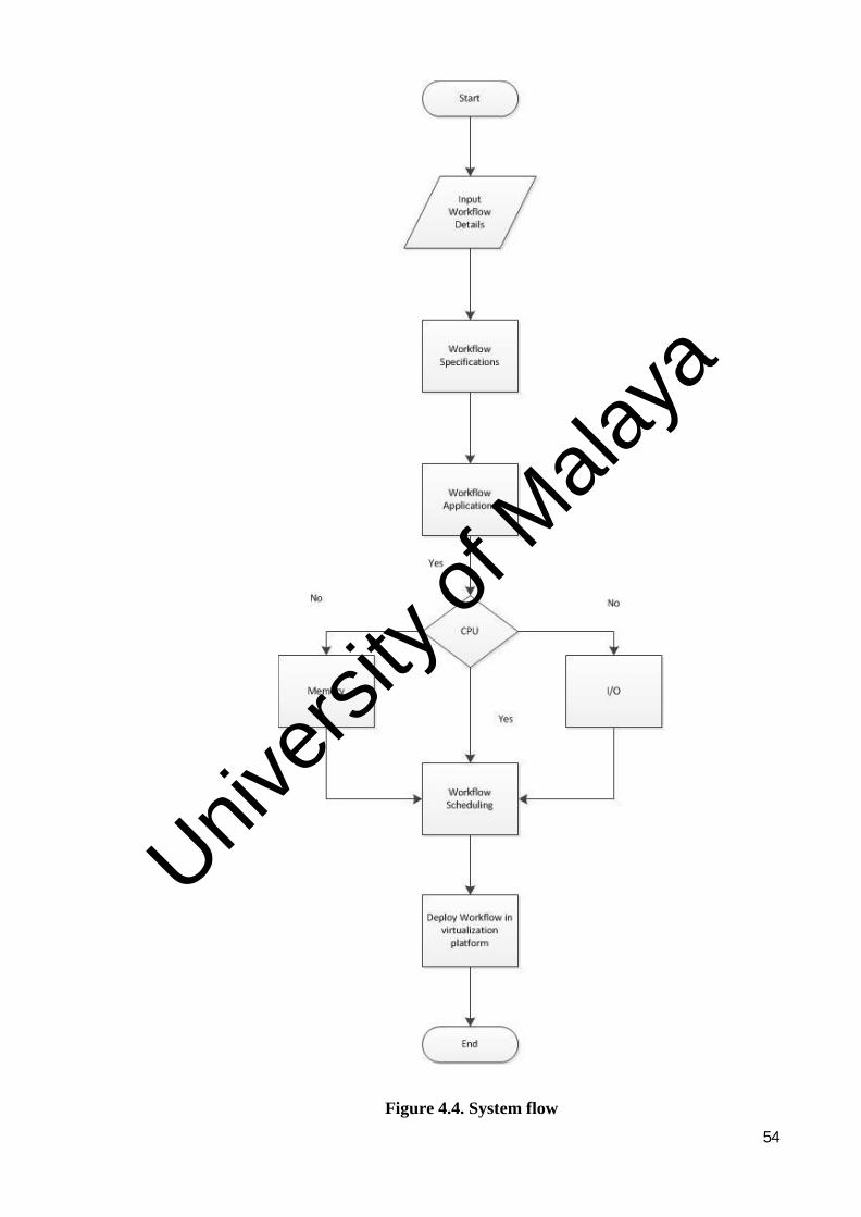
54
Figure 4.4. System flow
Univers
ity of
Mala
ya
55
4.2 System Implementation
At this phase, the system is implemented based on the defined automated system
architecture. Firstly, a performance database is developed. Then, a HTML form is
developed to ease user submission. Finally, the core components, namely orchestration,
scheduling and deployment are implemented.
4.2.1 Performance Database
Performance database is developed to gather and store the resource benchmark data.
A set of software tools is used to conduct the performance evaluation on the hypervisor-
based and container-based platform in terms of compute, memory, and I/O. SysBench
and Bonnie++ is selected as the evaluation tool for performance benchmark. Y-Cruncher
and STREAM will not be used as there are already a lot of other researchers using it for
performance evaluations. Furthermore, SysBench is an effective tool to measure the
performance of the applications. SysBench can handle looping test and the limit of each
test case can be configured. Bonnie++ is a small utility with the purpose of benchmarking
file system IO performance.
4.2.1.1 Compute Performance Testing Using Sysbench
Figure 4.5 shows the compute performance testing. The purpose of this test is to
measure how long would it takes for the system to fully execute this CPU intensive test.
This test verifies prime numbers with sequentially increasing and verifying that the
remainder or modulo calculation is zero. If it is, then the number is not prime and the
calculation goes on to the next number. Hence, if none have a remainder of 0, then the
Univers
ity of
Mala
ya
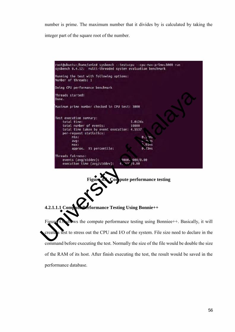
56
number is prime. The maximum number that it divides by is calculated by taking the
integer part of the square root of the number.
Figure 4.5. Compute performance testing
4.2.1.1.1 Compute Performance Testing Using Bonnie++
Figure 4.6 shows the compute performance testing using Bonniee++. Basically, it will
create a test to stress out the CPU and I/O of the system. File size need to declare in the
command before executing the test. Normally the size of the file would be double the size
of the RAM of its host. After finish executing the test, the result would be saved in the
performance database.
Univers
ity of
Mala
ya
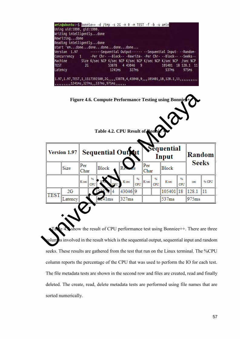
57
Figure 4.6. Compute Performance Testing using Bonniee++
Table 4.2. CPU Result of Bonnie ++
Table 4.2 show the result of CPU performance test using Bonniee++. There are three
columns involved in the result which is the sequential output, sequential input and random
seeks. These results are gathered from the test that run on the Linux terminal. The %CPU
column reports the percentage of the CPU that was used to perform the IO for each test.
The file metadata tests are shown in the second row and files are created, read and finally
deleted. The create, read, delete metadata tests are performed using file names that are
sorted numerically.
Univers
ity of
Mala
ya
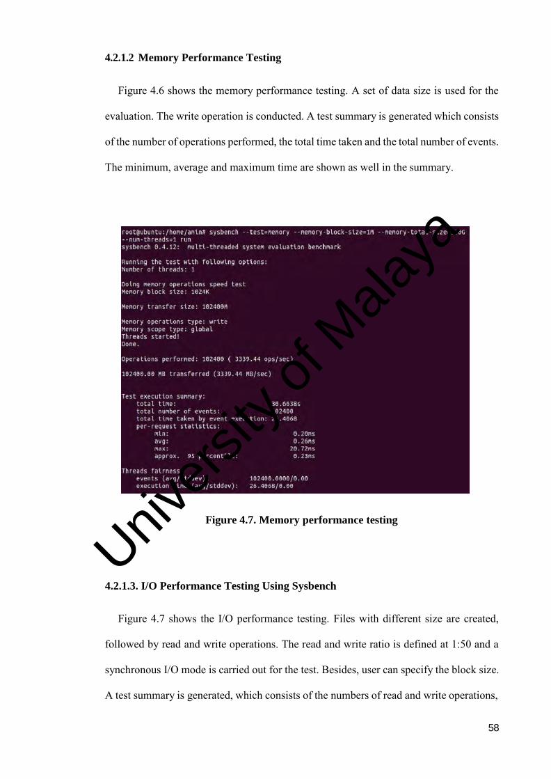
58
4.2.1.2 Memory Performance Testing
Figure 4.6 shows the memory performance testing. A set of data size is used for the
evaluation. The write operation is conducted. A test summary is generated which consists
of the number of operations performed, the total time taken and the total number of events.
The minimum, average and maximum time are shown as well in the summary.
Figure 4.7. Memory performance testing
4.2.1.3. I/O Performance Testing Using Sysbench
Figure 4.7 shows the I/O performance testing. Files with different size are created,
followed by read and write operations. The read and write ratio is defined at 1:50 and a
synchronous I/O mode is carried out for the test. Besides, user can specify the block size.
A test summary is generated, which consists of the numbers of read and write operations,
Univers
ity of
Mala
ya
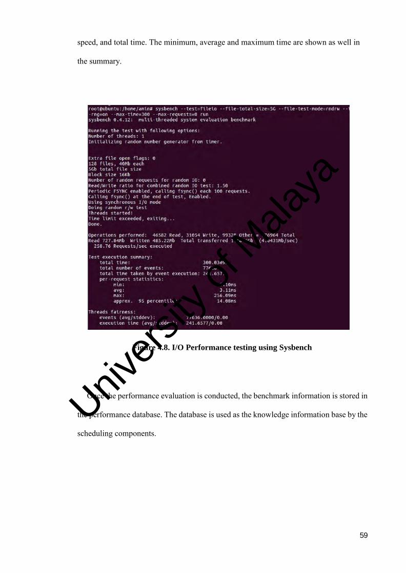
59
speed, and total time. The minimum, average and maximum time are shown as well in
the summary.
Figure 4.8. I/O Performance testing using Sysbench
Once the performance evaluation is conducted, the benchmark information is stored in
the performance database. The database is used as the knowledge information base by the
scheduling components.
Univers
ity of
Mala
ya
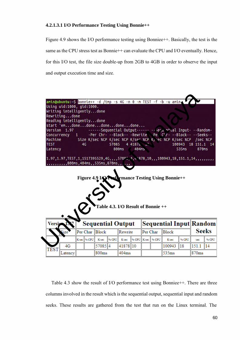
60
4.2.1.3.1 I/O Performance Testing Using Bonnie++
Figure 4.9 shows the I/O performance testing using Bonniee++. Basically, the test is the
same as the CPU stress test as Bonnie++ can evaluate the CPU and I/O eventually. Hence,
for this I/O test, the file size double-up from 2GB to 4GB in order to observe the input
and output execution time and size.
Figure 4.9 I/O Performance Testing Using Bonnie++
Table 4.3. I/O Result of Bonnie ++
Table 4.3 show the result of I/O performance test using Bonniee++. There are three
columns involved in the result which is the sequential output, sequential input and random
seeks. These results are gathered from the test that run on the Linux terminal. The
Univers
ity of
Mala
ya
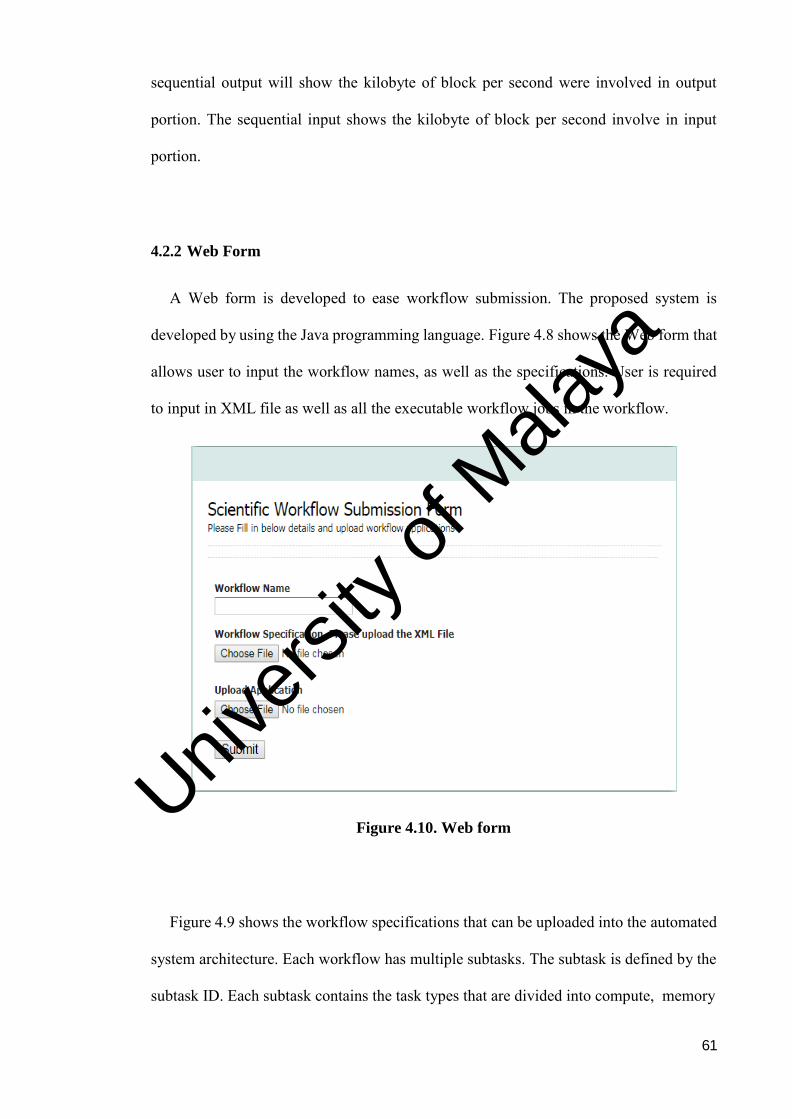
61
sequential output will show the kilobyte of block per second were involved in output
portion. The sequential input shows the kilobyte of block per second involve in input
portion.
4.2.2 Web Form
A Web form is developed to ease workflow submission. The proposed system is
developed by using the Java programming language. Figure 4.8 shows the Web form that
allows user to input the workflow names, as well as the specifications. User is required
to input in XML file as well as all the executable workflow jobs in the workflow.
Figure 4.10. Web form
Figure 4.9 shows the workflow specifications that can be uploaded into the automated
system architecture. Each workflow has multiple subtasks. The subtask is defined by the
subtask ID. Each subtask contains the task types that are divided into compute, memory
Univers
ity of
Mala
ya
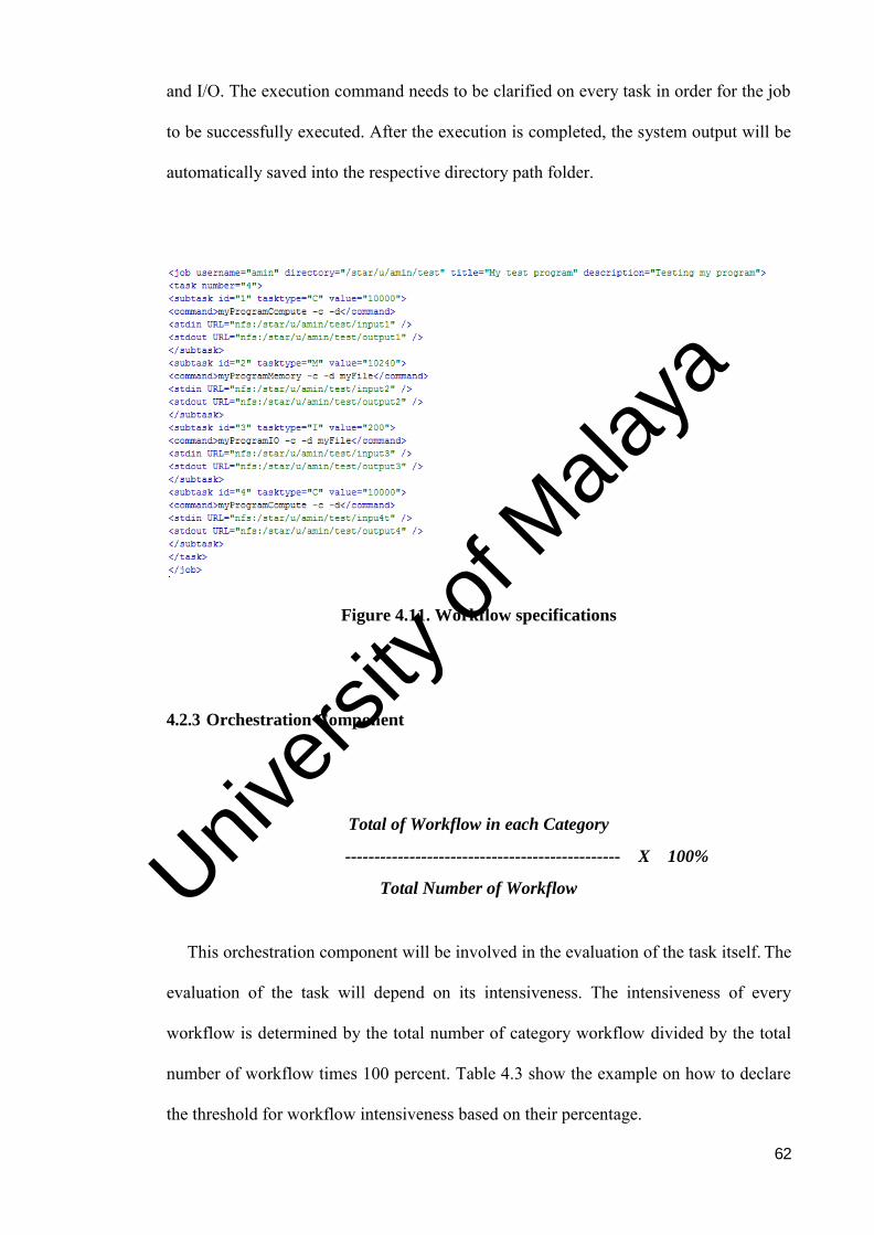
62
and I/O. The execution command needs to be clarified on every task in order for the job
to be successfully executed. After the execution is completed, the system output will be
automatically saved into the respective directory path folder.
Figure 4.11. Workflow specifications
4.2.3 Orchestration Component
Total of Workflow in each Category
----------------------------------------------- X 100%
Total Number of Workflow
This orchestration component will be involved in the evaluation of the task itself. The
evaluation of the task will depend on its intensiveness. The intensiveness of every
workflow is determined by the total number of category workflow divided by the total
number of workflow times 100 percent. Table 4.3 show the example on how to declare
the threshold for workflow intensiveness based on their percentage.
Univers
ity of
Mala
ya
63
Table 4.4 Example of Threshold for Choosing Workflow Intensiveness
Sequence
of task in a
workflow
Category Number of workflows
on each category
Total number of workflows
for each category
Total Percentage
for each category
1 CPU Intensive (A) 1/5 3/5
60% 2 CPU Intensive (B) 1/5
3 CPU Intensive (C) 1/5
4 I/O Intensive 1/5 1/5 20%
5 Memory Intensive 1/5 1/5 20%
Total 5/5 5/5 100%
Hence, the highest percent of the category will be declared as the most intensive
category for the workflow. If the task requires a lot of CPU resource allocation, then it
will be orchestrated together with another task which is in the same category. If the task
requires a lot of memory resources, then it will be separated into the same category. As if
the task is I/O intensive, it will be merged with the other task that requires massive I/O
resource allocations.
4.2.4 Scheduling Component
After the entire task was orchestrated into their category, the scheduling component
will schedule the task into different virtualization platforms, namely hypervisor-based
virtualization or container-based virtualization. Univ
ersity
of M
alaya
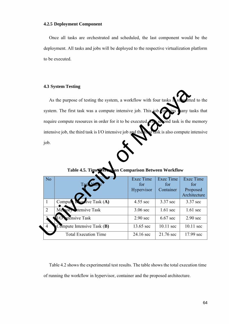
64
4.2.5 Deployment Component
Once all tasks are orchestrated and scheduled, the last component would be the
deployment. All tasks and jobs will be deployed to the respective virtualization platform
to be executed.
4.3 System Testing
As the purpose of testing the system, a workflow with four tasks is submitted to the
system. The first task was a compute intensive job. This job contains many tasks that
require compute resources in order for it to be executed. The second task is the memory
intensive job, the third task is I/O intensive job and the final task is also compute intensive
job.
Table 4.5. Time Execution Comparison Between Workflow
No
Task Name Exec Time
for Hypervisor
Exec Time for
Container
Exec Time for
Proposed Architecture
1 Compute Intensive Task (A) 4.55 sec 3.37 sec 3.37 sec
2 Memory Intensive Task 3.06 sec 1.61 sec 1.61 sec
3 I/O Intensive Task 2.90 sec 6.67 sec 2.90 sec
4 Compute Intensive Task (B) 13.65 sec 10.11 sec 10.11 sec
Total Execution Time 24.16 sec 21.76 sec 17.99 sec
Table 4.2 shows the experimental test results. The table shows the total execution time
of running the workflow in hypervisor, container and the proposed architecture.
Univers
ity of
Mala
ya

65
4.4 Chapter Summary
In this chapter, the system design of the proposed system architecture is described in
detail. Then, the system implementation is shown and explained. In the last phase, the
system testing procedures are discussed. In the next chapter the experiment testing is
discussed followed by result analyst and discussion.
Univers
ity of
Mala
ya
66
CHAPTER 5: RESULTS AND DISCUSSION
This chapter details the performance evaluation process of the proposed technique and
discussions on the obtained results. The chapter also presents the experimental setup by
using the hypervisor-based and container-based virtualization. The tests are carried out to
capture the result, which is the total execution time for each virtualization platform. After
the test is completed, the obtained results will be analysed for each technique. A chapter
summary is presented at the end of chapter.
5.1 Experimental Setup
The setup of the performance evaluation test is to evaluate the time taken for each
hypervisor-based and container-based virtualization platform to execute respective jobs
and tasks. Four different types of workflow specification are used, namely compute
intensive, memory intensive, I/O intensive and uniform intensive. Compute intensive
workflow consists of a higher rate of compute intensive tasks as per shown on Table 4.4,
which there are more than 60% of compute intensive task occur in one workflow. Same
goes with the memory intensive workflow which it consist a higher rate of memory
intensive tasks while I/O workflow consists of a higher rate of I/O intensive tasks. The
uniform workflow is the mixture of compute, memory and I/O intensive tasks. The
uniform workflow consists of a nearly equal distribution of the compute, memory and I/O
intensive tasks.
Table 5.1 shows the example of some of the workflow that was executed from the test
case. As shown in the table, every workflow has their own task and this task was sorted
by sequence based on their priority. Each workflow consisted of multiple tasks. Each task
was categorised as compute, memory or I/O intensiveness task. After the task and its
Univers
ity of
Mala
ya
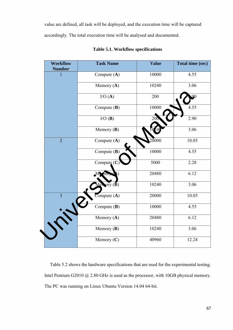
67
value are defined, all task will be deployed, and the execution time will be captured
accordingly. The total execution time will be analysed and documented.
Table 5.1. Workflow specifications
Workflow
Number
Task Name Value Total time (sec)
1 Compute (A) 10000 4.55
Memory (A) 10240 3.06
I/O (A) 200 2.90
Compute (B) 10000 4.55
I/O (B) 200 2.90
Memory (B) 10240 3.06
2 Compute (A) 20000 10.05
Compute (B) 10000 4.55
Compute (C) 5000 2.28
Memory (A) 20480 6.12
Memory (B) 10240 3.06
3 Compute (A) 20000 10.05
Compute (B) 10000 4.55
Memory (A) 20480 6.12
Memory (B) 10240 3.06
Memory (C) 40960 12.24
Table 5.2 shows the hardware specifications that are used for the experimental testing.
Intel Pentium G2010 @ 2.80 GHz is used as the processor, with 10GB physical memory.
The PC was running on Linux Ubuntu Version 14.04 64-bit.
Univers
ity of
Mala
ya
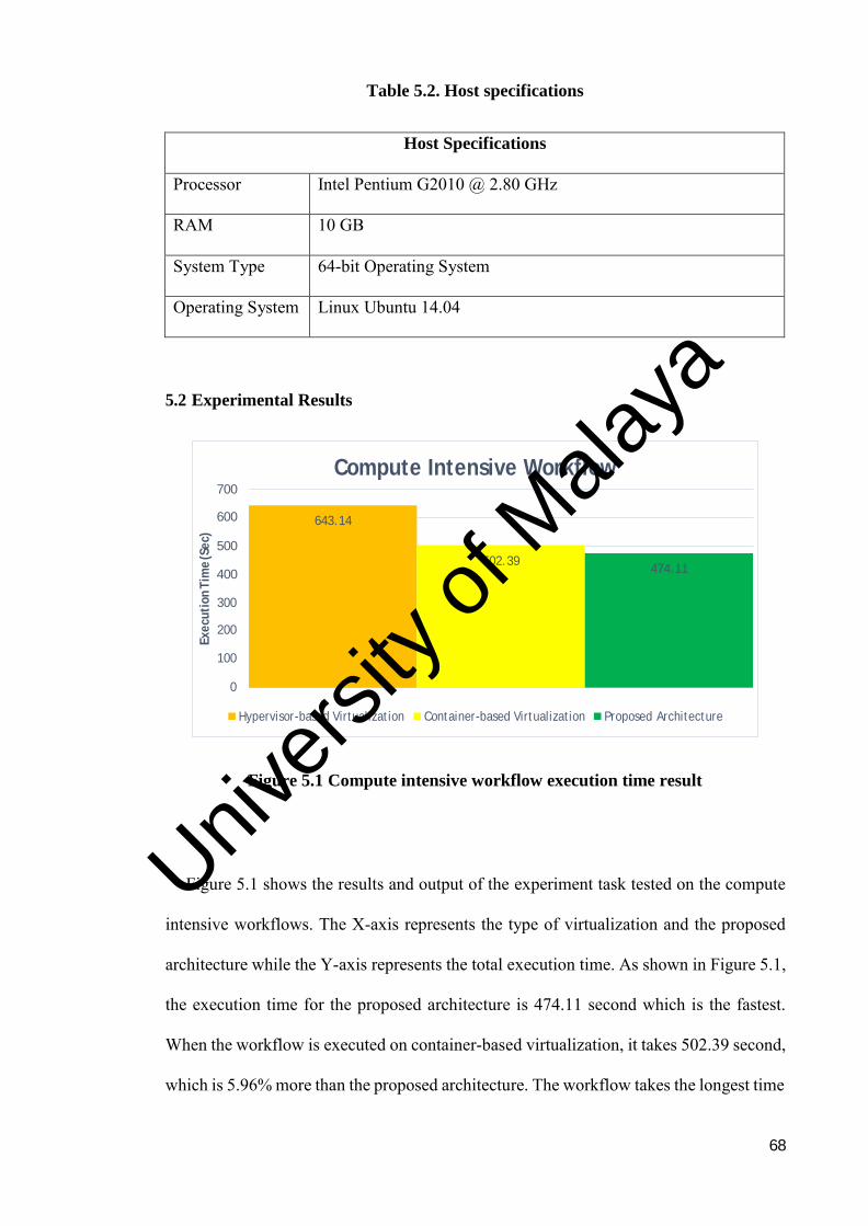
68
Table 5.2. Host specifications
Host Specifications
Processor Intel Pentium G2010 @ 2.80 GHz
RAM 10 GB
System Type 64-bit Operating System
Operating System Linux Ubuntu 14.04
5.2 Experimental Results
Figure 5.1 Compute intensive workflow execution time result
Figure 5.1 shows the results and output of the experiment task tested on the compute
intensive workflows. The X-axis represents the type of virtualization and the proposed
architecture while the Y-axis represents the total execution time. As shown in Figure 5.1,
the execution time for the proposed architecture is 474.11 second which is the fastest.
When the workflow is executed on container-based virtualization, it takes 502.39 second,
which is 5.96% more than the proposed architecture. The workflow takes the longest time
Hypervisor-based Virtualization Container-based Virtualization Proposed Architecture
300 200 100
0
474.11 400 502.39
500
643.14
700 600
Compute Intensive Workflow
Execu
tion
Tim
e (S
ec)
Univers
ity of
Mala
ya
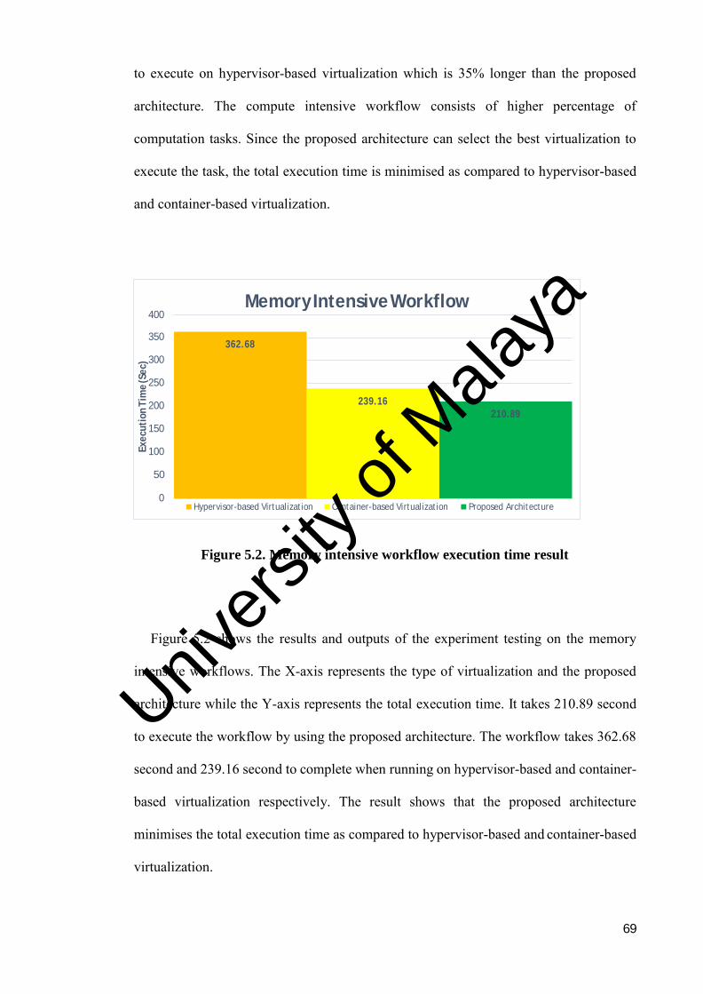
69
to execute on hypervisor-based virtualization which is 35% longer than the proposed
architecture. The compute intensive workflow consists of higher percentage of
computation tasks. Since the proposed architecture can select the best virtualization to
execute the task, the total execution time is minimised as compared to hypervisor-based
and container-based virtualization.
Figure 5.2. Memory intensive workflow execution time result
Figure 5.2 shows the results and outputs of the experiment testing on the memory
intensive workflows. The X-axis represents the type of virtualization and the proposed
architecture while the Y-axis represents the total execution time. It takes 210.89 second
to execute the workflow by using the proposed architecture. The workflow takes 362.68
second and 239.16 second to complete when running on hypervisor-based and container-
based virtualization respectively. The result shows that the proposed architecture
minimises the total execution time as compared to hypervisor-based and container-based
virtualization.
Memory Intensive Workflow 400 350 300 250 200 150 100 50
0
Hypervisor-based Virtualization Container-based Virtualization Proposed Architecture
210.89
239.16
362.68
Execu
tion
Tim
e (S
ec)
Univers
ity of
Mala
ya
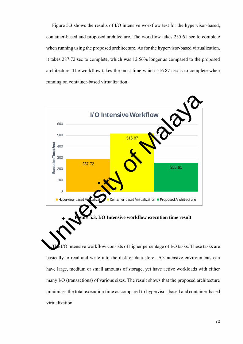
70
Figure 5.3 shows the results of I/O intensive workflow test for the hypervisor-based,
container-based and proposed architecture. The workflow takes 255.61 sec to complete
when running using the proposed architecture. As for the hypervisor-based virtualization,
it takes 287.72 sec to complete, which was 12.56% longer as compared to the proposed
architecture. The workflow takes the most time which 516.87 sec is to complete when
running on container-based virtualization.
Figure 5.3. I/O Intensive workflow execution time result
The I/O intensive workflow consists of higher percentage of I/O tasks. These tasks are
basically to read and write into the disk or data store. I/O-intensive environments can
have large, medium or small amounts of storage, yet have active workloads with either
many I/O (transactions) of various sizes. The result shows that the proposed architecture
minimises the total execution time as compared to hypervisor-based and container-based
virtualization.
I/O Intensive Workflow
600
500
400
300
200
100
0
Hypervisor-based Virtualization Container-based Virtualization Proposed Architecture
255.61 287.72
516.87
Execu
tion
Tim
e (S
ec)
Univers
ity of
Mala
ya
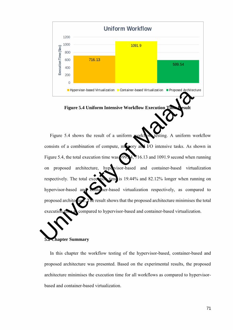
71
Figure 5.4 Uniform Intensive Workflow Execution Time Result
Figure 5.4 shows the result of a uniform workflow testing. A uniform workflow
consists of a combination of compute, memory and I/O intensive tasks. As shown in
Figure 5.4, the total execution time was 599.54, 716.13 and 1091.9 second when running
on proposed architecture, hypervisor-based and container-based virtualization
respectively. The total execution time is 19.44% and 82.12% longer when running on
hypervisor-based and container-based virtualization respectively, as compared to
proposed architecture. The result shows that the proposed architecture minimises the total
execution time as compared to hypervisor-based and container-based virtualization.
5.2 Chapter Summary
In this chapter the workflow testing of the hypervisor-based, container-based and
proposed architecture was presented. Based on the experimental results, the proposed
architecture minimises the execution time for all workflows as compared to hypervisor-
based and container-based virtualization.
Hypervisor-based Virtualization Container-based Virtualization Proposed Architecture
400 200
0
599.54
800 600 716.13
1091.9
1200 1000
Uniform Workflow
Execu
tion
Tim
e (S
ec)
Univers
ity of
Mala
ya
72
CHAPTER 6: CONCLUSION AND FUTURE DIRECTIONS
This chapter summarises the conducted research. It discusses the research contribution
in brief. Then, the suggestions for possible improvements are provided for future research
plans.
6.1 Thesis Summary
This research starts with exploring the underlying concepts, characteristics, system
architecture of the most famous virtualization technology, namely hypervisor-based and
container-based. Then, the performance evaluation strategies and tools are discussed and
analysed. Subsequently, the scientific workflow is explained briefly, and problem of the
current virtualization platform is identified.
During the investigation and analysis process, the problems of the workflows
deployment in the virtualization platform are identified. It is very challenging to deploy
the workflow tasks to the suitable virtualization platforms since the workflow consists of
compute, memory and I/O intensive tasks.
To address the above issue, an automated system architecture is proposed. The
proposed architecture consists of the core components namely orchestration, scheduling
and deployment that are able to minimise the workflow total execution time.
To validate the accuracy and effectiveness of the proposed architecture, the benchmark
is conducted to measure the performance of the virtualization platform. The performance
evaluation is conducted by using the performance evaluation tools called SysBench. Once
the result is obtained, the information is used as the knowledge-based for the proposed
automated architecture.
Univers
ity of
Mala
ya
73
Four different types of workflows are used for experimental testing. The experimental
result indicates that the proposed automated architecture outperformed the standard
deployment of the workflow in the hypervisor-based and container-based virtualization
platform by minimising the total execution time approximately 20%-30%. It is proven
that the proposed automated architecture reduces the total execution time as compared to
hypervisor-based and container-based virtualization.
6.2 Thesis Contribution
In this research, an automated system architecture is proposed and implemented. The
workflow orchestration, scheduling and deployment components are developed by using
Java programming language. Then, the proposed architecture is evaluated and tested by
using different workflow tasks, namely compute, memory and I/O intensive tasks. The
analysis is done based on the result that gained from the SysBench performance testing
tools. The experimental results indicated that the proposed architecture can minimise the
total execution time.
To summarise, this research has contributed in few areas.
First, it provides a deep understanding of workflow orchestration, scheduling and
deployment in the automation architecture. The automation system will orchestrate, group
and schedule the workflow before being deployed and executed into the respective
virtualization platform.
Secondly, in this study, the experimental results show that the proposed automation
architecture can reduce the total execution time of the workflow. The effectiveness of the
architecture is proven based on the measurements.
Univers
ity of
Mala
ya
74
Lastly, based on the experimental results, the proposed architecture can be used to
manage and deploy workflow in the virtualization environment, either it was on
hypervisor-based or the container-based.
6.3 Future Work Suggestions
Many research was done in hypervisor-based and container-based technologies.
However, there are many issues and challenges which have directed the research to be
further studied and explored. One of the major issues is the application performance on
the virtualization environment as many have claimed that their applications performance
was decreased after it was migrated into the virtualization platform.
A suggestion to further improve the current research is to consider the network
bandwidth of both virtualization platform since a network plays a big role in managing
applications. In addition, it is suggested to include the size of the workflow that will be
deployed to see if there is any difference if a mass size of workflow is deployed into both
virtualization platforms.
In summary, virtualization is one of the most advanced and emerging technologies for
Cloud computing and data centre. The advances in this technology will lead to a broad
and deep research in which the outcomes will benefit both administrators and users.
Univers
ity of
Mala
ya

75
REFERENCES
A. M. Joy, “Performance comparison between Linux containers and virtual machines,”
in Proc. 2015 Int. Conf. Adv. Comput. Eng. Appl. (ICACEA 2015). Ghaziabad,
India: IEEE Press, 14-15 Feb. 2015, 507–510.
Ankita Desai, Kumar, Rakesh, “An Importance of Using Virtualization Technology in
Cloud Computing,” February 2015.
C. Pahl, “Containerization and the PaaS Cloud,” IEEE Cloud Compute., vol. 2, no. 3, pp.
24–31, May/Jun. 2014.
D. Merkel, “Docker: Lightweight Linux containers for consistent development and
deployment,” Linux J., vol. 239, pp. 76–91, Mar. 2014.
D. Bernstein, “Containers and Cloud: From LXC to Docker to Ku-Bernetes,” IEEE Cloud
Comput., vol. 1, no. 3, pp. 81–84, Sept. 2014.
D. C. Montgomery. “Design and Analysis of Experiments” John Wiley & Sons, Inc.,
Hoboken, NJ, 7th edition edition, January 2009.
D. Merkel, “Docker: Lightweight Linux containers for consistent development and
deployment,” Linux J., vol. 239, pp. 76–91, Mar. 2014.
F. Wu, Q. Wu, Y. Tan, Workflow scheduling in Cloud: a survey, J. Supercomput. 2015
3373–3418.
H. Koziolek. “Performance evaluation of component-based software system” A survey.
Perform. Eval., August 2010.
K.-T. Seo, H.-S. Hwang, I.-Y. Moon, O.-Y. Kwon, and B.-J. Kim, “Performance
comparison analysis of Linux container and virtual machine for building Cloud,”
Adv. Sci. Technol. Lett., vol. 66, pp.105–111, Dec. 2014.
Univers
ity of
Mala
ya

76
M. Xavier, M. Neves, F. Rossi, T. Ferreto, T. Lange, C. De Rose, “Performance
evaluation of container-based virtualization for high performance computing
environments,” in: 21st Euromicro International Conference on Parallel,
Distributed and Network-Based Processing, (PDP), IEEE, 2013.
M.W. Convolbo, J. Chou, “Cost-aware DAG scheduling algorithms for minimizing
execution cost on Cloud resources,” J. Supercomput. 2016.
P.V.S.S. Gangadhar et al, “Distributed Memory and CPU Management in Cloud
Computing Environment,” Aug 2018.
R. Dua, A. R. Raja, and D. Kakadia, “Virtualization vs containerization to support PaaS,”
in Proc. 2014 IEEE Int. Conf. Cloud Eng. (IC2E 2015). Boston, Massachusetts,
USA: IEEE Computer Society, 10-14 Mar. 2014, 610–614.
S. F. Piraghaj, A. V. Dastjerdi, R. N. Calheiros, and R. Buyya, “Efficient virtual machine
sizing for hosting containers as a service,” in Proc. 11th World Congr. Serv.
(SERVICES 2015). New York, USA: IEEE Computer Society, 27 Jun.-2 Jul.
2015, 31–38.
T. Banerjee, “Understanding the key differences between LXC and Docker,”
https://www.flockport.com/lxc-vs-docker/, Aug 2014. T. Adufu, J. Choi, and Y.
Kim, “Is container-based technology a winner for high performance scientific
applications?” in Proc. 17th Asia-Pacific Network Oper. Manage. Symp.
(APNOMS 2015). Busan, Korea: IEEE Press, 19-21 Aug. 2015, 507–510.
W. Felter, A. Ferreira, R. Rajamony, and J. Rubio, “An updated performance comparison
of virtual machines and Linux containers,” in Proc. 2015 IEEE Int. Symp.
Perform. Anal. Syst. Software (ISPASS 2015). Philadelphia, PA, USA: IEEE
Press, 29-31 Mar. 2015, 171–172.
Univers
ity of
Mala
ya
77
X. Xu, H. Yu, and X. Pei, “A novel resource scheduling approach in container-based
Clouds,” in Proc. 17th IEEE Int. Conf. Computer. Sci. Eng. (CSE 2014).
Chengdu, China: IEEE Computer Society, 19-21 Dec. 2014, 257–264
Z. Li, L. O’Brien, and M. Kihl, “DoKnowMe: Towards a domain knowledge-driven
methodology for performance evaluation,” ACM SIGMETRICS Perform. Eval.
Rev., vol. 43, no. 4, 23–32, Mar. 2016.
Z. Li, L. O’Brien, H. Zhang, and R. Cai, “On the conceptualization of performance
evaluation of IaaS services,” IEEE Trans. Serv. Compute., vol. 7, no. 4, pp. 628–
641, Oct.-Dec. 2014. C. Anderson, “Docker,” IEEE Software, vol. 32, no. 3, 102–
105, May/Jun. 2015.
Univers
ity of
Mala
ya