Embed Size (px)
Citation preview

AUTOMATED SYSTEM FOR TAPES GEOMETRY MEASUREMENT
RF089 Series

Tapes geometry measurement system
[Version 1.0] 08th December 2014
2
Contents
1. Safety precautions ................................................................................................................ 3 2. Electromagnetic compatibility ............................................................................................... 3 3. Laser safety .......................................................................................................................... 3 4. General information .............................................................................................................. 3 5. Structure and operating principle .......................................................................................... 3 6. Basic technical data ............................................................................................................. 5 7. Overall and mounting dimensions......................................................................................... 6
7.1. Measurement modules ................................................................................................. 6 7.2. PDA .............................................................................................................................. 7
8. Block diagram ...................................................................................................................... 7 9. Cable connections scheme................................................................................................... 8 10. Software ............................................................................................................................... 8
10.1. Main functions .............................................................................................................. 8 10.2. Measurements .............................................................................................................. 8 10.3. Calibration .................................................................................................................. 10
10.3.1. Calibration of the thickness measurement micrometers ...................................... 10 10.3.2. Thermometers calibration ................................................................................... 11
10.4. Settings ...................................................................................................................... 11 10.5. Measurement journal .................................................................................................. 12
11. Intended use ...................................................................................................................... 14 11.1. Prepatation for use ..................................................................................................... 14
11.1.1. External inspection .............................................................................................. 14 11.1.2. Set up on a conveyer .......................................................................................... 14 11.1.3. Switching the system .......................................................................................... 14 11.1.4. Calibrating the system ......................................................................................... 14 11.1.5. Configuring system settings ................................................................................ 14 11.1.6. Checking the system ........................................................................................... 14
11.2. Operating the system .................................................................................................. 14 12. Maintenance ....................................................................................................................... 15
12.1. General instructions .................................................................................................... 15 12.2. Safety precautions ...................................................................................................... 15 12.3. Maintenance procedure .............................................................................................. 15
12.3.1. Daily maintenance work ...................................................................................... 15 12.3.2. Regular maintenance work.................................................................................. 15 12.3.3. Yearly maintenance work .................................................................................... 15
12.4. Operability test ............................................................................................................ 15 13. Warranty policy................................................................................................................... 15

Tapes geometry measurement system
[Version 1.0] 08th December 2014
3
1. Safety precautions
Use supply voltage and interfaces indicated in the sensor specifications.
In connection/disconnection of cables, the micrometer power must be switched off.
Do not use micrometers in locations close to powerful light sources.
To obtain stable results, wait about 20 minutes after micrometer activation to achieve uniform micrometer warm-up.
Elements of the system should be grounded and join the grounding bus through a separate line.
2. Electromagnetic compatibility
The system have been developed for use in industry and meet the requirements of the following standards:
EN 55022:2006 Information Technology Equipment. Radio disturbance charac-teristics. Limits and methods of measurement.
EN 61000-6-2:2005 Electromagnetic compatibility (EMC). Generic standards. Immunity for industrial environments.
EN 61326-1:2006 Electrical Equipment for Measurement, Control, and Labora-tory Use. EMC Requirements. General requirements.
3. Laser safety
The micrometers make use LED or c.w. 660 nm wavelength semiconductor la-ser. Maximum laser output power is <0,2 mW. The micrometers belong to the 1 laser safety class. The following warning label is placed on the laser body.
The following safety measures should be taken while operating the sensor:
Avoid staring into the laser beam during a prolonged time period;
Do not disassemble the micrometer.
4. General information
The system is designed to control the geometrical parameters (width and thick-ness) and the temperature of the tapes, in particular, packing straps during the manufac-turing process.
The system is applied in the mass production. Production line is the place of in-stallation.
Technical characteristics of the system can be changed for a specific task.
5. Structure and operating principle
Optical micrometers are used to control the geometrical parameters of the tapes. The principle of width measurement is shown in the Fig.1
Tapes geometry measurement system
[Version 1.0] 08th December 2014
4
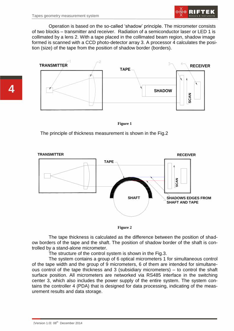
Operation is based on the so-called ‘shadow’ principle. The micrometer consists of two blocks – transmitter and receiver. Radiation of a semiconductor laser or LED 1 is collimated by a lens 2. With a tape placed in the collimated beam region, shadow image formed is scanned with a CCD photo-detector array 3. A processor 4 calculates the posi-tion (size) of the tape from the position of shadow border (borders).
SC
AN
TAPERECEIVERTRANSMITTER
SHADOW
Figure 1
The principle of thickness measurement is shown in the Fig.2
SC
AN
TAPE
RECEIVERTRANSMITTER
SHAFT SHADOWS EDGES FROMSHAFT AND TAPE
Figure 2
The tape thickness is calculated as the difference between the position of shad-ow borders of the tape and the shaft. The position of shadow border of the shaft is con-trolled by a stand-alone micrometer.
The structure of the control system is shown in the Fig.3. The system contains a group of 6 optical micrometers 1 for simultaneous control
of the tape width and the group of 9 micrometers, 6 of them are intended for simultane-ous control of the tape thickness and 3 (subsidiary micrometers) – to control the shaft surface position. All micrometers are networked via RS485 interface in the switching center 3, which also includes the power supply of the entire system. The system con-tains the controller 4 (PDA) that is designed for data processing, indicating of the meas-urement results and data storage.

Tapes geometry measurement system
[Version 1.0] 08th December 2014
5
Figure 3
6. Basic technical data
Parameter Value
Model of micrometer RF651-25
Model of PDA RF307
Model of temperature sensor OMEGA OS-136-1-MA
Number of tapes controlled simultaneously 6
Number of temperature control points 3
Measurement range for the tape thickness, mm 0,02…20
Accuracy of the thickness measurement, um ±5
Measurement range for the tape width, mm ±0,2…20
Accuracy of the width measurement, um ±10
Max measurement speed, measurement/s 2000
Power supply
three-phase AC network with frequency (50 ± 1) Hz, rated voltage 220/380V with
a tolerance of ±10% voltage
Power consumption, W 4
Operation conditions Temperature, °С: +1..+35
0С
Rel. humidity at 250С 65

Tapes geometry measurement system
[Version 1.0] 08th December 2014
6
7. Overall and mounting dimensions
7.1. Measurement modules
Fig. 5 and 6 show the dimensions of measurement modules as well as their instal-lation on equipment.
Figure 4
Figure 5

Tapes geometry measurement system
[Version 1.0] 08th December 2014
7
7.2. PDA
RF307 device is intended to process the data from the micrometers indicate re-sults and store the data.
Fig. 6 shows overall dimensions of the device.
Figure 6
8. Block diagram
Fig. 7 shows the block diagram of the system. Optical micrometers RF651 are linked via RS485 interface. Temperature sen-
sors are included in the same network via ADC. The information from all micrometers and temperature sensors comes to the PDA RF307.
Figure 7

Tapes geometry measurement system
[Version 1.0] 08th December 2014
8
9. Cable connections scheme
Fig. 8 shows the cable connections.
Figure 8
Fig. 8 indicates:
1– power supply, 2 – PDA, 3,6 – RS485 cable, 4 – switching center, 5 – power supply, 7 – micrometers RF651 (15 items), 8 – temperature sensors (3 items).
(!) The power should be switched off while mounting cable connections.
10. Software
10.1. Main functions
The software provides:
receipt and analysis of data from micrometers and temperature sensors with
display and storage of measurement results;
indication out of the valid values;
calibration of thickness measurement subsystem;
system setup;
system self-diagnosis.
10.2. Measurements
After being switched on the RF307 device loads the program and shows the main working window (Fig. 9):

Tapes geometry measurement system
[Version 1.0] 08th December 2014
9
Figure 9
Press Start to initiate the measurement process. The results of measuring the
width of strips are shown in the upper left part of the window, thickness – in the upper
right and temperature – in the central part.
The width of the tape is the result of direct measurement of the micrometer.
The thickness of the tape - the result of indirect measurements, calculated as
follows:
Thickness=(Tape_sp-Shaft_cl) - (Shaft_sp - Shaft_cl),
where Tape_sp – the current position of the upper surface of the tape (indicated by the
main micrometers, see P. 5.),
Shaft_cl – position of the shaft surface (main micrometers) while system calibra-
tion (see P.10.3.),
Shaft_sp – the current position of the shaft surface (indicated by subsidiary mi-
crometers, see P.5),
Shaft_cl – position of the shaft surface (subsidiary micrometers) while system
calibration.
To control the current thickness indications from 9 micrometers press the Dis-
play button.
When the current indication goes beyond the tolerance, the corresponding
measurement is highlighted in orange (Fig. 10).
The tolerance installation procedure is described in the p.10.4.
If the micrometer is not responding, it is highlighted in red.
The measurement results are stored in SQLite database file named «keep.db»
at the root of the PDA flash drive, see point.10.5.

Tapes geometry measurement system
[Version 1.0] 08th December 2014
10
Figure 10
10.3. Calibration
10.3.1. Calibration of the thickness measurement micrometers
Calibration procedure:
remove tapes from the shaft
start measurement process by pressing «Start»
open the calibration menu: Settings > Set etalon/Sw. State (Fig. 11)
select the numbers of the micrometers to be calibrated (numbers 7-15 corre-
spond to 9 micrometers of the tape thickness control subsystem)
make sure that Etalons mode is selected and Set option in Mode field is on
than press Apply button
Figure 11

Tapes geometry measurement system
[Version 1.0] 08th December 2014
11
10.3.2. Thermometers calibration
stop the calibration process by pressing Stop button
open the calibration menu Settings > Calibration (Fig. 12)
choose the number of temperature sensor (Sensor index field)
direct the sensor to the surface with stated temperature, having entered the
temperature value in Temp. 1 or Temp. 2 field and press Set button. When the
operation is finished successfully the message Calibration parameter has
been successfully set appears. Detailed information on temperature sensors
can be found in OMEGA OS136-1-MA documentation
perform the operation described in the previous paragraph for two different
temperatures. By pressing the Set button the previous calibration value is over-
written
Figure 12
10.4. Settings
All sensors in the system are numbered (Index) from 1 to 18, where the 1-6 match the sensors 1-6 from width measurement group of sensors, numbers 7-15 in the Settings match the sensors 1-9 from width measurement group of sensors and numbers 16-18 match the three temperature sensors. Indexes T1-T6 indicates the results of indi-rect thickness measurement.
To perform the system settings enter the General menu.
in the Timeout field the delay in milliseconds between successive cycles of
the sensors polling is set
to set the tolerances choose the number of the sensor in the Index field and
set the upper and lower limits in the fields Upper limit and Lower limit corre-
spondingly
to set the production task number use the field Task Number
Tapes geometry measurement system
[Version 1.0] 08th December 2014
12
to enable or disable the recording of measurements in the database, use the
field Save log
with the use of Time and Date fields the system date and time can be set
in the Free space field the empty space on a removable device is shown (mi-
cro SD card)
to apply polling period and tolerances settings press Apply
to undo all the changes press Discard
to add/remove the devices participating in the poll and to calibrate microme-
ters enter the menu Set etalon/Sw. State. The top button also serves as an in-
dicator and switch modes, namely, States – the mode of active devices selec-
tion is active; Etalons – the mode of setup/reset of micrometers calibration is ac-
tive. Use the States function to disable the devices that are not used in the poll-
ing during the system operation. It is necessary when the device is faulty or is
not in use, neglecting the recommendation above may cause long delays while
polling and therefore the entire system delay. The use of the Etalons mode is
described in the paragraph 10.3.1
to set the number of measurements used to calculate an average value use
the Averaging field.
10.5. Measurement journal
During operation the system generates measurement journal. To view the
measurement log enter the Journal menu (Fig. 13). This menu is intended for viewing
the measurements stored on a flash drive in the SQLite database file named keep.db.
Each entry has the following structure:
Time – measurement time.
Task – production task number.
Type – measurement type (temperature, width, thickness).
Measure # – number of measurement of a particular type (Corresponds to the
Index notion, described in the paragraph 10.4).
Value – measured/calculated value.
To display the item you need use the filters:
Time range – time range selection.
Values range – selection of the displayed measured values range.
Task – production task number.
Type – measurement type (Device – value received from the device; Thickn. –
calculated thickness; Temp. - temperature).
Measure # – number of the measurement device of a particular type.
In order to fulfill the request to display the records matching the selected fil-
ters, click Apply. To reset the filter values to their default values, click Clear. Table with
records supports vertical scrolling, sorting by columns by clicking on the table top and
row highlighting. By default, sorting is done on time: first the records that were saved be-
fore. Table records can be saved in the root of the flash drive as * .csv file. In .csv files
the columns are separated with a semicolon. Click Export CSV to save the file. The
name of the file includes the date and time when it was saved. After the file was saved
the message (Fig. 14) appears.

Tapes geometry measurement system
[Version 1.0] 08th December 2014
13
Figure 13
Figure 14
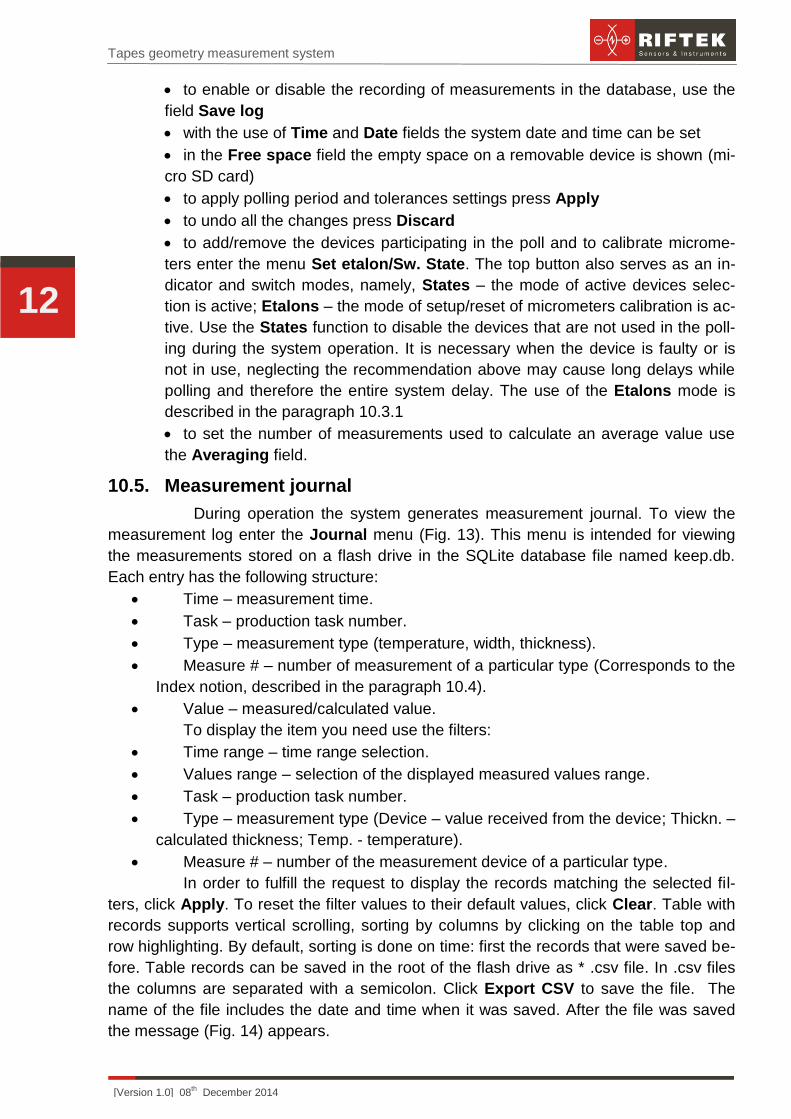
NOTE. To enter the date and time values are special graphics components shown in
Figures 15 and 16, respectively. To enter numeric values use keypad, Figure 17.
Figure 15
Tapes geometry measurement system
[Version 1.0] 08th December 2014
14
Figure 16
Figure 17
When typing the corresponding values the keyboard appears automatically.
11. Intended use
11.1. Prepatation for use
Preparation of the system includes:
external inspection;
set up on a conveyer;
switching the system;
calibrating the system;
system setup.
11.1.1. External inspection
Before operating it is needed to ensure of the serviceability of the equipment,
check the cables, ground wires. Check the condition of output windows of the scanner
and, if necessary, wipe them with a soft cloth.
11.1.2. Set up on a conveyer
Install the system on a conveyer according to the Fig. 2-5 of this manual. Make
the electrical connections in accordance with the Fig. 8.
11.1.3. Switching the system
11.1.4. Calibrating the system
Выполнить калибровку системы в соответствии с п. 10.3.2 настоящего руководства. Калибровка установки производится: Calibrate the machine according to the Para-graph 10.3.2. Calibration should be held:
on a weekly basis before the work shifts,
if the position of the system was changed,
when the ambient temperature has changed (several degrees in average per day in relation to the previous day).
11.1.5. Configuring system settings
Configure the settings according to the Paragraph 10.4 and 10.5.
11.1.6. Checking the system
To check the functionality of the system conduct a full cycle control of the geo-metrical parameters of the control sample tape. It is recommended to conduct at list one functional test of the system in a month.
11.2. Operating the system
The geometric parameters measurement cycle is fully automated and operation of the system is reduced to the work with the program.
prepare the system according to the Paragraph 11.1.
to start the measurement process press the Start button.
Tapes geometry measurement system
[Version 1.0] 08th December 2014
15
12. Maintenance
12.1. General instructions
Maintenance of the system is carried out to ensure constant-ready status and continued availability of its work and to prevent premature failure. Maintenance includes preventive measures aimed at identification and elimination of defects and to ensure the normal operation while installation and working. It is recommended to conduct the daily, weekly and annual maintenance work.
12.2. Safety precautions
During the installation maintenance security measures outlined in the Paragraph 1 should be observed.
12.3. Maintenance procedure
12.3.1. Daily maintenance work
Daily maintenance includes:
visual inspection of the system
checking of completeness,
checking for any damage of the structural elements, power and instrument cables, indicators and connectors,
weakening of screw connections and insulation failures,
before starting work, it is necessary to clean the output micrometer windows with a soft dry cloth.
12.3.2. Regular maintenance work
Regular maintenance work includes:
cleaning of micrometer windows with a dry soft lint-free cloth from contamina-tion of dirt.
12.3.3. Yearly maintenance work
Authenticated calibration of the micrometers should be made once a year.
12.4. Operability test
It is recommended to conduct the functional test at least once at the beginning or during the shift, for what it is necessary to complete full cycle control of the geometrical parameters of the control sample (not supplied).
13. Warranty policy
Warranty assurance for the Tape measurement system - 12 months from the date of putting in operation; warranty shelf-life - 12 months.