Embed Size (px)
Citation preview
International Research Journal of Engineering and Technology (IRJET) e-ISSN: 2395-0056
Volume: 04 Issue: 07 | July -2017 www.irjet.net p-ISSN: 2395-0072
© 2017, IRJET | Impact Factor value: 5.181 | ISO 9001:2008 Certified Journal | Page 651
AUTOMATIC CROP MONITORING USING EMBEDDED SYSTEM
Mr.Takkasila Akbar Saleem 1, Mr. K Sreenivasa Rao 2
1 M.Tech student, Embedded Systems, Dept of ECE
2M.Tech, MISTE, MIE, (PhD), Associate Professor, Dept of ECE Annamacharya Institute of Technology and Sciences, Rajampet, Kadapa, Andhra Pradesh, India
---------------------------------------------------------------------------***--------------------------------------------------------------------------Abstract: Many advanced techniques introduced in agriculture automation to flourish and deliver its full potential. To get more benefits of these technologies, we should not just consider the implication of developing a new single technology but should look at the wider issues for complete development of a system. This system designed by using LPC2148 microcontroller to overcome limitations of agriculture farming about supplying of water to plants by drip system with the available water tables. In our system we use LPC2148 microcontroller, motor pump, soil moisture sensor. The motor pump operates based on soil condition that is soil wet or dry; if soil wet motor stops else motor run to give water to plants. The status of motor displayed on first row of LCD There is also a rain sensor whenever rain fall occur then also motor off irrespective of soil condition. The temperature and dangerous CO gas also verified by using different sensors connected to controller. In case any critical situation occurs through these sensors an SMS sent to owner. An electrical fence also included to keep strangers away from field by its slight shock. Authorized persons presence identified by using RFID module interfaced to controller when RFID card carried by that person near field. In this case electrical fence deactivated hence no shock by fence. Keywords: LPC2148, soil moisture, temperature, rain, Co sensors, RFID module, electrical fence, GSM, motor pump. 1. Introduction Irrigation is the major problem in agriculture in the countries which are in developing stage. In any country which is like India where the income of people depends on agriculture directly or indirectly and the environmental conditions are isotropic still we are unable to use agriculture resources. The main cause low rainfall due to this more land not irrigated. Another very important reason unplanned usage of water resources by this way more water goes waste. By the drip system water supplied to plants zone only remaining area can’t get water due to this large amount of water saved. Automatic irrigation system can supply water to plants whenever they need water when power supply intervals. Here no need of turning ON/OFF valves. By this automatic irrigation system watering plants at exact time based on soil
condition which will improves crop growth by taking water and minerals from soil when plants needed. The current work aims to sensor network based low cost soil moisture, temperature monitoring system to track the soil moisture and temperature in real time and there by allow water given to plants based on conditions of soil moisture, temperature and type of crop grown in soil. The sensors take the inputs like moisture, temperature and provide these inputs to the
microcontroller. The microcontroller converts these inputs into its desired form with the program that is running on it and gives outputs in the mode of regulation of water flow according to the present input conditions. The sensors take the inputs like moisture, temperature and provide these inputs to the micro controller. The microcontroller converts these inputs into its desired form with the program that is running on it and gives outputs in the mode of regulation of water flow according to the present input conditions. There is also a rain sensor, so whenever this sensor detects the rain then also the motor will be off irrespective of soil condition. The temperature and dangerous CO gas is also verified using different sensors which are interfaced to the controller. In case, critical situation detected through these sensors then a SMS is sent to the owner. An electrical fence is also included to keep the strangers away from the field by it’s slight shock. Presence of a person is detected through PIR sensor and then led indication with buzzer alert will be given in case of unauthorized person’s appearance. Authorized person’s presence is identified using RFID module interfaced to the controller since the RFID card is being carried by that candidate, in this case electric fence will be deactivated
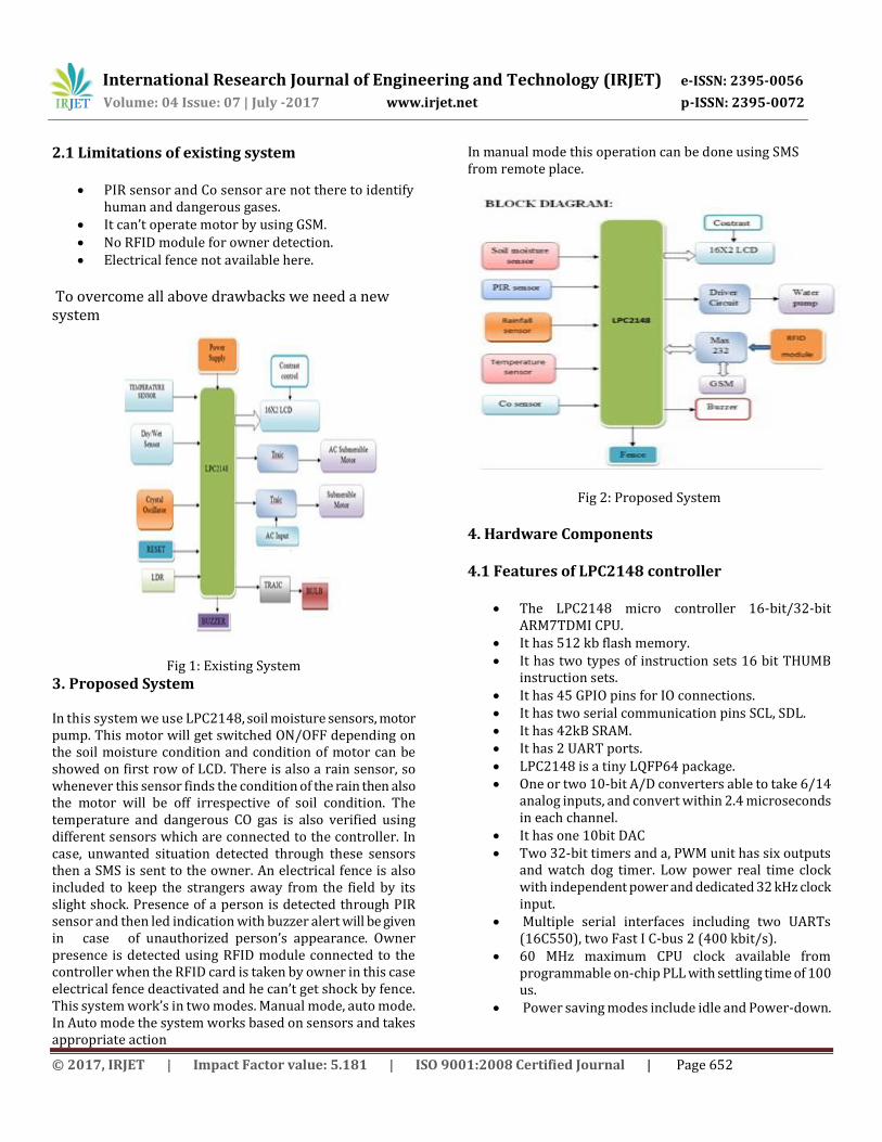
hence doesn’t produce any shock. 2. Existing System This system implemented by using LPC2148, soil moisture sensor, motor pump, triac combination with MOC 3021 based opto isolator which drives motor, temperature sensor, LDR sensor. A motor will turn ON /OFF based on soil condition and the temperature increases in the field. The status of motor can be showed on16X2 LCD. To find the day and night mode we used LDR sensor, Triac with bulb. The status of LDR can be showed on LCD.
International Research Journal of Engineering and Technology (IRJET) e-ISSN: 2395-0056
Volume: 04 Issue: 07 | July -2017 www.irjet.net p-ISSN: 2395-0072
© 2017, IRJET | Impact Factor value: 5.181 | ISO 9001:2008 Certified Journal | Page 652
2.1 Limitations of existing system
PIR sensor and Co sensor are not there to identify human and dangerous gases.
It can’t operate motor by using GSM. No RFID module for owner detection. Electrical fence not available here.
To overcome all above drawbacks we need a new system
Fig 1: Existing System
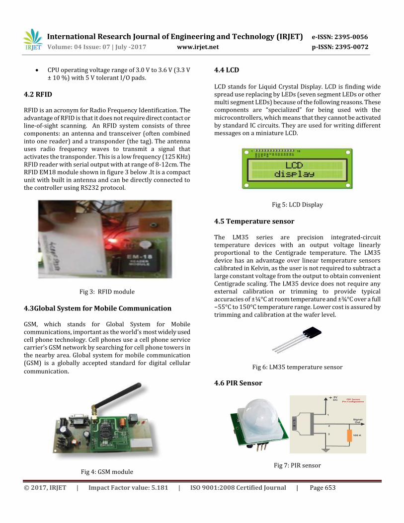
3. Proposed System In this system we use LPC2148, soil moisture sensors, motor pump. This motor will get switched ON/OFF depending on the soil moisture condition and condition of motor can be showed on first row of LCD. There is also a rain sensor, so whenever this sensor finds the condition of the rain then also the motor will be off irrespective of soil condition. The temperature and dangerous CO gas is also verified using different sensors which are connected to the controller. In case, unwanted situation detected through these sensors then a SMS is sent to the owner. An electrical fence is also included to keep the strangers away from the field by its slight shock. Presence of a person is detected through PIR sensor and then led indication with buzzer alert will be given in case of unauthorized person’s appearance. Owner presence is detected using RFID module connected to the controller when the RFID card is taken by owner in this case electrical fence deactivated and he can’t get shock by fence. This system work’s in two modes. Manual mode, auto mode. In Auto mode the system works based on sensors and takes appropriate action
In manual mode this operation can be done using SMS from remote place.
Fig 2: Proposed System
4. Hardware Components 4.1 Features of LPC2148 controller
The LPC2148 micro controller 16-bit/32-bit ARM7TDMI CPU.
It has 512 kb flash memory. It has two types of instruction sets 16 bit THUMB
instruction sets. It has 45 GPIO pins for IO connections. It has two serial communication pins SCL, SDL. It has 42kB SRAM. It has 2 UART ports. LPC2148 is a tiny LQFP64 package. One or two 10-bit A/D converters able to take 6/14
analog inputs, and convert within 2.4 microseconds in each channel.
It has one 10bit DAC Two 32-bit timers and a, PWM unit has six outputs
and watch dog timer. Low power real time clock with independent power and dedicated 32 kHz clock input.
Multiple serial interfaces including two UARTs (16C550), two Fast I C-bus 2 (400 kbit/s).
60 MHz maximum CPU clock available from programmable on-chip PLL with settling time of 100 us.
Power saving modes include idle and Power-down.
International Research Journal of Engineering and Technology (IRJET) e-ISSN: 2395-0056
Volume: 04 Issue: 07 | July -2017 www.irjet.net p-ISSN: 2395-0072
© 2017, IRJET | Impact Factor value: 5.181 | ISO 9001:2008 Certified Journal | Page 653
CPU operating voltage range of 3.0 V to 3.6 V (3.3 V ± 10 %) with 5 V tolerant I/O pads.
4.2 RFID RFID is an acronym for Radio Frequency Identification. The advantage of RFID is that it does not require direct contact or line-of-sight scanning. An RFID system consists of three components: an antenna and transceiver (often combined into one reader) and a transponder (the tag). The antenna uses radio frequency waves to transmit a signal that activates the transponder. This is a low frequency (125 KHz) RFID reader with serial output with at range of 8-12cm. The RFID EM18 module shown in figure 3 below .It is a compact unit with built in antenna and can be directly connected to the controller using RS232 protocol.
Fig 3: RFID module
4.3Global System for Mobile Communication GSM, which stands for Global System for Mobile communications, important as the world’s most widely used cell phone technology. Cell phones use a cell phone service carrier’s GSM network by searching for cell phone towers in the nearby area. Global system for mobile communication (GSM) is a globally accepted standard for digital cellular
communication.
Fig 4: GSM module
4.4 LCD LCD stands for Liquid Crystal Display. LCD is finding wide spread use replacing by LEDs (seven segment LEDs or other multi segment LEDs) because of the following reasons. These components are “specialized” for being used with the microcontrollers, which means that they cannot be activated by standard IC circuits. They are used for writing different messages on a miniature LCD.
Fig 5: LCD Display
4.5 Temperature sensor The LM35 series are precision integrated-circuit temperature devices with an output voltage linearly proportional to the Centigrade temperature. The LM35 device has an advantage over linear temperature sensors calibrated in Kelvin, as the user is not required to subtract a large constant voltage from the output to obtain convenient Centigrade scaling. The LM35 device does not require any external calibration or trimming to provide typical accuracies of ±¼°C at room temperature and ±¾°C over a full −55°C to 150°C temperature range. Lower cost is assured by trimming and calibration at the wafer level.
Fig 6: LM35 temperature sensor
4.6 PIR Sensor
Fig 7: PIR sensor
International Research Journal of Engineering and Technology (IRJET) e-ISSN: 2395-0056
Volume: 04 Issue: 07 | July -2017 www.irjet.net p-ISSN: 2395-0072
© 2017, IRJET | Impact Factor value: 5.181 | ISO 9001:2008 Certified Journal | Page 654
A Passive Infra Red sensor (PIR sensor) shown in figure is an electronic device. It measures infrared (IR) light radiating from objects in its field of view. PIR sensors are often used in the construction of PIR-based motion detectors. Apparent motion is detected when an infrared source with one temperature, such as a human, passes in front of an infrared source with another temperature, such as a wall. Detecting range: 360 degrees cone angle,
15-20 feet... Single bit high/low output. 4.7 CO sensor
Fig 8: co sensor
Sensitive material of MQ-7 gas sensor shown in figure is SnO2, which has lower conductivity in clean air. It can finds by the process of cyclic high and low temperature, and finds CO when low temperature. The sensor’s conductivity is higher along with the gas concentration increasing. When high temperature (heated by 5.0V), it cleans the other gases adsorbed under low temperature. Please use simple electro circuit, Convert change of conductivity to correspond output signal of gas concentration. MQ-7 is high sensitivity to Carbon Monoxide. The sensor used to find different gases contains CO; it is low cost and suitable for different application. CO sensor is a device that finds the presence of the CO in surrounding environment concentrations between 20 to 2000 ppm .
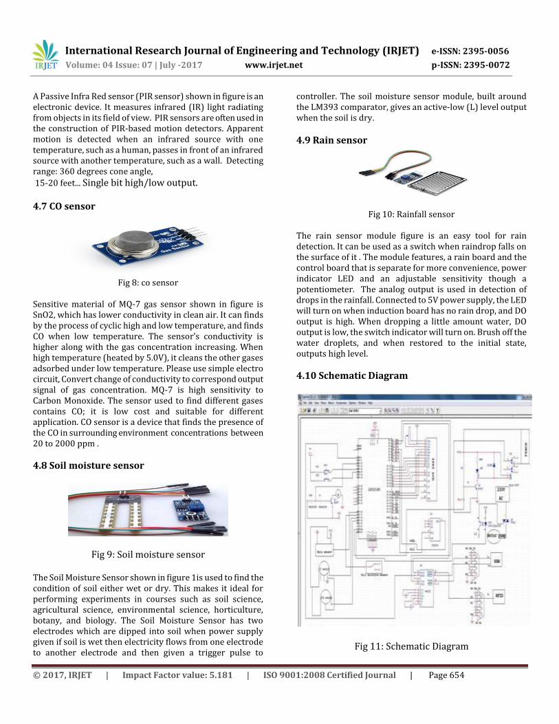
4.8 Soil moisture sensor
Fig 9: Soil moisture sensor
The Soil Moisture Sensor shown in figure 1is used to find the condition of soil either wet or dry. This makes it ideal for performing experiments in courses such as soil science, agricultural science, environmental science, horticulture, botany, and biology. The Soil Moisture Sensor has two electrodes which are dipped into soil when power supply given if soil is wet then electricity flows from one electrode to another electrode and then given a trigger pulse to
controller. The soil moisture sensor module, built around the LM393 comparator, gives an active-low (L) level output when the soil is dry.
4.9 Rain sensor
Fig 10: Rainfall sensor The rain sensor module figure is an easy tool for rain detection. It can be used as a switch when raindrop falls on the surface of it . The module features, a rain board and the control board that is separate for more convenience, power indicator LED and an adjustable sensitivity though a potentiometer. The analog output is used in detection of drops in the rainfall. Connected to 5V power supply, the LED will turn on when induction board has no rain drop, and DO output is high. When dropping a little amount water, DO output is low, the switch indicator will turn on. Brush off the water droplets, and when restored to the initial state, outputs high level.
4.10 Schematic Diagram
Fig 11: Schematic Diagram

International Research Journal of Engineering and Technology (IRJET) e-ISSN: 2395-0056
Volume: 04 Issue: 07 | July -2017 www.irjet.net p-ISSN: 2395-0072
© 2017, IRJET | Impact Factor value: 5.181 | ISO 9001:2008 Certified Journal | Page 655
5. Working of system First connect PIR sensor connector electrical fence connector at respective places then insert a SIM card in GSM SIM slot. Now switch on power supply switch and on the switch in trainer board and wait for getting signal in GSM . After getting signal in GSM press the switch s0 (num) and reset switch near microcontroller and wait for getting message as waiting for call in LCD. Then make a call to that number which is present in GSM slot. When call received then ring occur and that number displayed in LCD and that number stored in external memory interfaced to controller. This number is saved for further information sending to owner when abnormal conditions detected. Whenever he wants to change his number again he can change number by above procedure. Now keep the soil moisture sensor in soil near root zone of plant. The wet soil acts as conductor between two electrodes of soil moisture sensor. If the soil is wet a short circuit forms between two electrodes then power supply passes from one electrode to another electrode through wet soil. At this condition controller takes action to switch off motor and at this abnormal condition controller sends a message to owner through GSM as use copper oxy chloride. 3gmsplit near root zone of plants because of this wet condition crop may affected by root rot so protecting crop from root rot use copper oxy chloride. If sensor detects dry condition then motor switch on by sending pulses to motor pump from controller. When the temperature crosses 35 degree centigrade then controller sends message to owner use 19:19:19to spray on leaves of small crops for protecting crop from sun's effect. Because if sun's heat high temperature crop growth decreases so to avoid it use that fertilizer. The temperature always monitored and displayed on LCD which is detected by temperature sensor. When poissioness gases like CO, methane concentration increases in surrounding detected by co gas sensor and intimates to farmer. When rain fall occur then rain drops fall on rain sensor then short circuit forms between lines of rain sensor plate then controller sends a signal to motor to switch off irrespective of soil condition. Again rain fall stops then based on soil condition motor operation occurs. When any motion detected in particular range surrounding to field by PIR sensor and sends signal to controller then controller sends signal to buzzer and electrical fence. Then fence activated and small voltage passes through fence to give shock when the living beings come near to field.
An RFID system used here to detect owner and deactivate fence when authorized person come near to field by carrying this RFID tags with them. For this purpose take RFID tag and enroll its number to controller by placing near to reader. The reader sends that data to controller and stored in external memory connected to controller and stored in that memory. whenever farmer reach field by taking this card the electrical fence deactivated automatically again he wants to enable fence he can press a switch which is at controller board but any unauthorized cards taken by unauthorized persons they can’t detected by system and not deactivated due to this they reach near to field PIR sensor detects motion within the range and activates fence and he affected by fence. These all actions takes automatically in AUTO mode whenever farmer wants to stop motor or run motor irrespective of sensor's action ie soil and rain sensors action by sending message from authorized mobile number to system. The message to stop motor send #M OFF* The message to run motor send as #M ON* Again go to auto mode send message as #AUTO* In auto mode the actions can takes place based on sensor's action. Manual mode i.e. when message send by farmer then it enters into manual mode. In this mode all sensors work properly except rain and soil moisture sensor. In manual mode farmer can able to switch on Switch off motor only. In this way this system effectively operated in two modes manual and auto modes and helps in monitoring ,protecting crop from wild animals d thieves.
6. Results
Fig12: Experimental Hardware Setup

International Research Journal of Engineering and Technology (IRJET) e-ISSN: 2395-0056
Volume: 04 Issue: 07 | July -2017 www.irjet.net p-ISSN: 2395-0072
© 2017, IRJET | Impact Factor value: 5.181 | ISO 9001:2008 Certified Journal | Page 656
Fig13: Experimental Electrical Fence Setup
The figure above shows the experimental hardware setup and electrical fence for automatic crop monitoring using embedded technology. The below figure shows experimental outputs in LCD when different conditions occur. When this system detected abnormal conditions like high temperature greater than or equal to 35degree centigrade this system sends a message to owner to protect crop from high temperature and sun effect use 19:19:19 spray on crops like tomato, chili, and small banana plants. When detected high moisture in soil it causes root rot in crops like tomato mirchi banana turmeric then this system detect that moisture condition and sends that information to owner to protect crop from root rot use copper oxy chloride 3gmspltr use at root zone of plants. When farmer wants to switch on motor manually by sending message from his mobile to system a message as"#M ON* “and to switch off motor when he wants then send message as "#M OFF*”. Again he wants change in auto mode he send a message from his mobile to system as "#AUTO*". The below figures shows inputs from mobile to system &outputs get to mobile from system.
Fig14: Experimental Output in LCD when different conditions occur
Here RFID system interface to controller used to deactivate electrical fence when farmer reach field by taking RFID tags and also he wants to activate electrical fence he press a switch manually which is present at system board when he leaving field . Due to PIR sensor any motion detected electrical fence activated and buzzer ring occur the motion may occur due to wild animals or thieves and also when farmer came then due to RFID system electrical fence deactivated PIR sensor action not considered but remaining sensors work properly When rain detected by rain sensor motor switched off irrespective of soil condition and again when rain fall stopped then based on soil condition motor switched on occur When any harmful gases like CO detected then this system intimates to owner through GSM owner will take appropriate action to protect crop from poissioness gasses In this way this system helpful for crop monitoring and
protecting. .
Fig 15: Input given from mobile to system &outputs get to mobile from system
7. Advantages
Reliability Ease of Operation Useful to detect harmful gases
8. Applications
Gardens Farms Agriculture
9. Conclusion Irrigation has been the back bone of human civilization since man has started agriculture. As the generation evolved, man
International Research Journal of Engineering and Technology (IRJET) e-ISSN: 2395-0056
Volume: 04 Issue: 07 | July -2017 www.irjet.net p-ISSN: 2395-0072
© 2017, IRJET | Impact Factor value: 5.181 | ISO 9001:2008 Certified Journal | Page 657
developed many methods of irrigation to supply water to the land. In the present scenario on conservation of water is of high importance. Present work is attempts to save the natural resources available for human kind. By continuously monitoring the status of the soil, we can control the flow of water and thereby reduce the wastage. By knowing the status of moisture, CO and temperature through GSM with the use of moisture and temperature sensors, water flow can be controlled by just sending a message from mobile.
10. Reference
1. An Effective Method for Crop Monitoring Using Wireless Sensor Network - N. Sakthipriya
2. A Wireless Sensor Network Solution for Precision Agriculture Based on ZigBee Technology – Manijeh Keshtgari
3. A Real Time Irrigation Control System For Precision Agriculture Using WSN In Indian Agricultural Sectors - Prathyusha.K
4. Survey on Bacterial Diseases of crop and Non-crops of Cuddapah District, Andhra Pradesh, India. R.HareKondaiah and A. Sreeramulu
5. Gwyn A. Beattie. 2006. Plant-Associated Bacteria : survey, molecular phylogeny, genomics and recent advances, Samuel S. Gnanamanickam editor ,Springer Netherlands pp. 1-5
6. Lopez, M. Rosello and A. Palacio-Bielsa .2010. Diagnosis and Detection of the Main Bacterial Pathogens of Stone Fruit and Almond. Journal of Plant Pathology.92 (1) S1.57-S1.66
7. Principles of electronics by V.K.Mehta 8. Basic electronics by Boylested 9. www.etvannadatha.com