Embed Size (px)
Citation preview

X-523-67-302
• i
AUTOMATIC. ELECTRONIC
POLARIZATION TRACKING SYSTEM
BY
RALPH E. TAYLOR
JUNE1967
GODDARDSPACEFLIGHTCENTERGREENBELT,MARYLAND
(ACCESSION NUMBER) (THRU)
r
(NASA CR OR TM_K OR AD NUMBE_J (CATEGORY}
\\
https://ntrs.nasa.gov/search.jsp?R=19680001798 2018-05-29T15:50:40+00:00Z

\

X-523-67-302
AUTOMATIC ELECTRONIC POLARIZATION
TRACKING SYSTEM
by
Ralph E. Taylor
June 1967
GODDARD SPACE FLIGHT CENTER
Greenbelt, Maryland


AUTOMATIC ELECTRONIC POLARIZATION
TRACKING SYSTEM
by
Ralph E. Taylor
ABSTRACTAn automatic electronic method is described that continuously
tracks, and measures to better than one-degree, the polarization
orientation angle of a linearlypolarized signal from a satellite such
as ATS-F&G. Comparable systems utilize a mechanically rotating
antenna feed.
All linear polarizations are comprised of two circularly po-
larized components of opposite sense. This system measures the
RF phase difference between the two oppositely polarized compo-nents to determine the linear polarization ormntation angLe. This
report also describes an error analysis that defines orientation
angle errors introduced by antenna ellipticity ratio and thermal
noise.
The polarization tracking technique described herein is ap-
plicable to the 2 GHz ATS-F&G proposed ground equipment and the
4 GHz Apollo Instrumentation Ship (AIS) SATCOM ground-terminal
stations using a 30 foot diameter dish antenna with cassegrainian
feed.
°°°
111


PRECEDING PAGE BLANK NOT FILMED.
CONTENTS
ABSTRACT ..........................................
INTRODUCTION .......................................
DESCRIPTION OF ELECTRONIC POLARIZATION TRACKING
TECHNIQUE ......................................... 2
Error Analysis .................................... 10
Feed Characteristics ................................ 12
NETWORK APPLICATIONS ............................... 13
ATS-F&G ........................................ 13
Apollo SATCOM (Satellite Communications) ................. 14
CONCLUSIONS ........................................ 14
ACKNOWLEDGMENT .................................. 14
REFERENCES ............................. ; .......... 14
APPENDIX 1 ......................................... 16
Page
iii
1
V


Figure
1
2
3
4
5
ILLUSTRATIONS
Page
Electronic Polarization Tracking System .............. 3
Antenna Signal Phase Characteristics ................ 6
Phase Diagram of _ and A Signals ................... 8
Polarization Error Function ....................... 11
Motor Driven Feed Type Polarization Tracking System for
ATS-B (Rosman 2) . ..................... ....... 15
Table
1
2
TABLES
Angular Error, A_0, Versus _ ....................
Angular Error in 8 0 Due to Thermal Noise .............
Page
10
12
vi


AUTOMATIC ELECTRONIC PO_ .RIZATION
TRACKING SYSTEM
INTRODUCTION
A concept is developedthat provides an automatic electronic methodforcontinuously tracking, and consequentlyaccurately measuring to better thanone-degree, the polarization orientation angle of a linearly polarized signaltransmitted from a spacecraft or other airborne vehicle. A critical require-ment for placing a synchronous spacecraft in its proper orbit is the determina-tion of the spacecraft attitude. The attitude is obtainedby measuring thepolarization orientation angle, as a function of time, during the transfer orbit.This time related data is necessary to control the spacecraft to the requiredapogeefiring attitude, predict the exact firing time, andfire the apogeemotorfor missions such as the Applications Technology Satellite (ATS-F&G).
Various methods are now available for measuring the polarization orienta-tion angle. For example, the National Aeronautics and SpaceAdministration's(NASA)SpaceTracking and Data Acquisition Network (STADAN)Rosman, N.C.No. 2 85-foot diameter dish antennautilizes a rotating motor-driven 4 GHzantennafeed,(1) in conjunction with a servo loop, that performed this functionfor the ATS-B spacecraft launchedonDecember 7, 1966. An undesirable featureof this technique is the mechanically rotating antennafeed with its associatedoperational problems andlarge size. An electronic-type system, employedbyVogt,(2) is complicated and does not have sufficient accuracy.
The electronic polarization tracking technique, subsequentlydescribed, hasthe following advantages:
(1) Eliminates the mechanical rotating antennafeed,
(2) Determines angular orientation of a linearly polarized vector to better
than 1 ° as a linear function of the radio frequency (RF) phase difference
between two coherent circularly polarized signals of opposite sense,
(3) Utilizes a conventional "off-the-shelf" simultaneous-lobing monopulse
type autotrack receiver as the polarization tracking receiver, and,
(4) Utilizes a servo loop, similar to the Rosman No. 2 Polarization
Tracking System, as a part of the null-seeking tracking loop.

A description of the RosmanNo. 2 motor-driven type Polarization TrackingSystem is given in the attached Appendix 1.
DESCRIPTION OF ELECTRONIC POLARIZATION TRACKING TECHNIQUE
All linear polarizations can be considered as a combination of two circularlypolarized waves with the respective electric vectors rotating in oppositedirec-tions.(2,3) In order to resolve these twovectors, the receiving antennamustprovide two circularly pol--arizedsignal output ports with opposite sense (geeFigure 1 Block Diagram). It will be shownthat the differential RF phasebetweenthese two oppositely polarized componentsis a constant for any givenorientation angle, 80.
The proposed system utilizes a null-seeking servo loop wherein acontinuously-adjustable phase-shifter, in a transmission line, gives an ac-curate readout of 80. The system is relatively insensitive to input signallevel changessince a sum-and-difference amplitude ratio is the driving func-tion for the servo. A decided advantageis that a conventionalautotrack receivercanbe used as the polarization tracking receiver.
The receiving antenna(e.g. 30 foot dish) provides two circularly polarizedoutputs consisting of left-hand, _LH' and tight'hand, XRH, signal components
(see Figure 1 block diagram).
Reference 4 shows that the left-hand (counter-clockwise) circularly
polarized wave can be designated by the vector,
The corresponding right-hand (clockwise) rotating circularly polarized
wave as,
a x and ay are unit vectors in right'handed coordinate system. Then, for zero
phase difference between oppositely polarized components,
: _LH + _-_'RH " (3)
2

¢.O
ADJUSTABLE PHASE **POLARIZATIONLINEAR _1 SHIFTER RECEIVER
POLAR ]// L._.___.._$ LHOL_
R I I
I _ow-_
I
ANTENNA
(e.g. 30 FT.)
I MOTORX/4 - 3 X/4 COAXIAL DRIVE
RF HYBRI D. I
STANDARD UNIT J
(e.g. TELEDYNE 105A IOR ITTFL 4003AUTO TRAC K J
RECEIVER).
DISH _ i
_.eLOHOr I
I [
l
J DIGITALOPTICAL
ENCODER
H SERVO J"
ANTENNAMOUNTED
_ IN-HOUSE
I
I-IIIIIIJ
_0
Figure 1. Electronic Polarization Tracking System.

From (3), the electric field vector can be written as:
-- ZL_ exp (- JPL_) + EI_ exp (-j/3RH ) (4)
flRH' flLH = respective RF phase of RH andLH components from 0° reference.From (1), (2) and (4),
= a x E x + ay Ey (5)
E x = (_)[exp (-jfl_H)+ exp (-j/3R_)] (6)
Ey = (-_)Ij exp (-JfiLH)- J exp (-JfiRH)] (7)
The angular rotation angle, 8 0 , is given by
(8)
Factoring out exp [± 0.5 j(flLH+ /3RH)] from (6) and (7) obtains
Ex = E1 exp [-0"5j(/3LH +/3RH)] C SO I_RI'I-_LI'I2 (9)
Ey--- E2 exp [- 0.5 j(/_LH +/_Rtt)] sirll/_RH ;/_LH ] (lO)
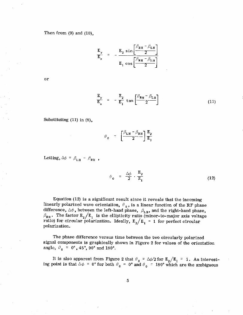
Then from (9) and (10),
EY
EX
E 2 sin 2
_RH -_LH 1E 1 cos 2
or
Ey
EX
tan (11)
Substituting (11) in (8),
_LH-_RH] E2_o = 2
Letting, 3¢ = /_LH - /_RH '
(12)
Equation (12) is a significant result since it reveals that the incoming
linearly polarized wave orientation, 80 , is a linear function of the RF phase
difference, A¢, between the left-hand phase, flLH, and the right-hand phase,
flRH" The factor E2/E 1 is the ellipticity ratio (minor-to-major axis voltage
ratio) for circular polarization. Ideally, E2/E 1 = 1 for perfect circularpolarization.
The phase difference versus time between the two circularly polarized
signal components is graphically shown in Figure 2 for values of the orientation
angle, 80 = 0 ° , 45 °, 90 ° and 180 °.
It is alSO apparent from Figure 2 that 80 = A¢/2 for E2/E I = 1. An interest-
ing point is that A¢ = 0 ° for both 80 = 0 ° and 80 = 180 ° which are the ambiguous
5

CIRCULAR I
POLARIZATION
L.H._
R.H. __)
0 ° REF.
L.H._
R.H.
LINEAR
POLAR _, ^o
VECTOR _
L.H. 2_
R.H. 2_
1
ooA¢ 0 °
O''4 ___ -_,_j _ _,M_
ERH
•o S
_..,,,y_ -._j- _:9o°
!_ 180 °
0 °
L.H. 2_
R.H. 2_
0 (_ = 180 °
. _ _ _¢ = 0 °+ L
o_
Figure 2. Antenna Signal Phase Characteristics.

points. However, this ambiguity need not be resolved since only the location of
a plane is required. A calibration boresight antenna would be utilized to es-
tablish the A¢ = 0 ° reference plane (see Figure 2).
It is now apparent that a suitable technique is desired to accurately measure
the RF phase difference, L_¢. The use of a direct-reading phase measuring
system such as a minitrack-type interferometer, or a dual-channel phase-lock
system, could be used to accomplish this function. However, a simpler scheme
is to use a null-indicating device to measure _. An amplitude sum-and-
difference ratio can be generated to indicate _ and hence 80 .
Such a system employs a continuously adjustable phase shifter that auto-
matically corrects for the phase difference, A¢, to maintain an in-phase
relationship at the two inputs to an RF hybrid (see Figure 1). The resulting
and _ channels are amplified in low-noise preamplifiers and frequency
converted from 2 GHz down to 136 MHz. A conventional autotrack receiver
produces the sum-and-difference ratio utilized to drive the servo.
The two circular polarization output transmission lines are critical, in
terms of differential phase and amplitude variations, from the antenna to the
two input arms of the sum-and-difference RF hybrid in that these parameters
directly affect 80 . However, these parameters are readily controlled sincethese lines are short. The sum-and-difference RF hybrid generates sum-and-
difference signals that are relatively insensitive to differential phase and
amplitude changes in the output lines. For example, the normal gain and phase
changes between preamplifiers (i.e., 1 db and 5°), and remotely located (up to
1500 ft. away) polarization tracking receiver channels (i.e., 2 db and 10°), no
longer affect the accuracy of the orientation angle measurement.
A motor-driven adjustable phase shifter is suggested since the phase rates
are not large. A digital optical encoder, such as a Wayne-George type 12-bit
encoder, would provide a convenient remote readout of 80 with a precision
better than 0.1 °. An alternate method would be to monitor 80, directly, as an
indicator output from the servo electronics.
An electronic phase-shifter, such as a ferrite device, could be incorporated
instead of the mechanical phase shifter. However, the problems associated with
high insertion loss and maintaining good phase linearity off-set advantages of a
ferrite phase shifter. In any event, a motor-driven phase shifter is vastly superior
to a motor-driven antenna feed.
The sum-and-difference ratio, 151/1_1 , from the polarization tracking re-
ceiver is derived as follows. The _ component (see Figure 3a) from the RF

0 jJ
fJ
JJ
_LH
/1t/ I_
ZRH COS A_
(a) VECTOR SUM COMPONENTS
//
4
//
//
- ...... _I_
Iz\\
_LH 0 _RHCOS A_
(b) VECTOR DIFFERENCE COMPONENTS
Figure 3. Phase Diagram of _ and A Signals.
hybrid can be expressed as
Sum,_ : (_L.÷_=Hco=_¢) + j X=.sin _¢ (13)
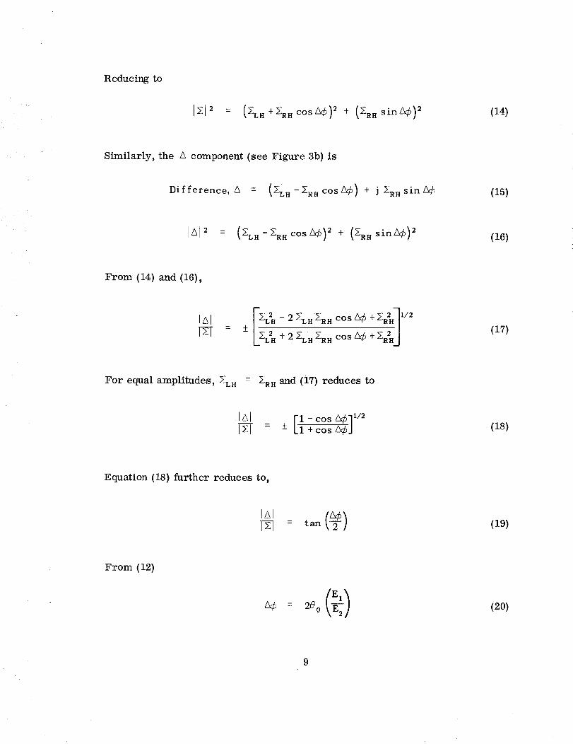
Reducingto
I_I_ = (_LH+_RHOOS_¢)_+ (_RHsin_¢)_ (14)
Similarly, the A component (see Figure 3b) is
Difference, A = (XLH-:RHCOSZ_b) + j 2RnSin_ (15)
IAI _ : (_.=,-_,cos_¢)= + (_,sin_¢) = (16)
From (14) and (16),
!ZXlY_
_L2H - 2 XLH_RH COS _ + _R2It__ 1/2+_
L_ZH+=_,.H_RHCOS'_+_#HJ(17)
For equal amplitudes, 5:LH = 2RH and (17) reduces to
IAI [iI- cos A¢]I/2I_1 - -+ +cos_CJ (18)
Equation (18) further reduces to,
1_-_ = tan (19)
From (12)
(20)

Substituting(20) in (19)
IAII_I - an _o (21)
Equation (21) is the servo error function obtained from the tracking re-
ceiver product detector. A plot of (21) is shown in Figure 4 for a ratio of
El/E 2 = I. 03 corresponding to an antenna circular polarization ellipticityratio of 0.3 db.
The servo system will always make IAI/Izl = o, for values of 8o <_+where 8 o is measured from the 0 ° reference plane. The automatic phase-shifter,
therefore, continuously adjusts for A¢ to maintain an in-phase relationship
between the two input ports of the _ and A hybrid. The shaft rotation of the
automatic phase-shifter gives a direct indication of 80 .
Error Analysis
Table i is a tabulation of the polarization orientation variations for various
values of A¢ and 80 for an antenna ellipticity ratio of 0.3 db. Table 1 indicates
that this system comes close to achieving the design goal of 1 °, or better. How-
ever, a 0.3 db antenna ellipticity ratio means that the antenna must be practically
perfect. The variation in 80, due to the ellipticity ratio, can be reduced using
a rotating calibration boresight source. It should be possible to maintain &90 < 1°
through appropriate preflight calibration which would relax the ellipticity ratio
to about 0.5 db. 80 ideal is obtained for perfect circular polarization where
E1/E 2 = 1.
Table 1
Angular Error in _0, versus /_¢
E LLIPTICITY
RATIO
0.3 db
0.3 db
0.3 db
A¢
45 °
90 °
135 °
8 o
INDICATED
21.8 °
43.7 °
65.5 °
8 o
IDEAL
22.5 °
45.0 °
67.5 °
A8 o
0.7 °
1.3 °
2.0 °
10

ZlE
I--,-J
O
O
TAN (I .03 _o)
-50 ° _30 ° _20 ° _10 ° 10° 20° 30° 40° 50°
POLARIZATION VECTORORIENTATION
-0.2
Figure 4. Polarization Error Function.
11

Another factor which limits the accuracy of _ is the polarization tracking
signal-to-noise ratio (SNR). This thermal noise error is expressed as,
(s)_ = 57.3 degrees rms . (22)
The corresponding polarization orientation error is A_ 0 = _A¢/2 for an
antenna ellipticity ratio, E2/E 1 = 1.
Table 2
Angular Error in 80 Due to Thermal Noise
S/N(POWER RATIO)
+ 4O db
+ 50 db
+ 60 db
0.57 ° rms
0.18 ° rms
0.057 ° rms
_0
0.29 ° rms
0.09 ° rms
0.029 ° rms
It is apparent from Table 2 that a SNR > + 40 db should be maintained to
keep the polarization orientation error, due to thermal noise, less than 0.3 ° rms
to achieve a peak error of 1°, or less. An input SNR of + 40 db is fairly high butis not difficult to achieve. Calculations show that a nominal SNR > + 40 db can be
maintained for the S-band down-link carrier signal for the polarization angle
measurement. This SNR can be obtained in a 1 Hz loop tracking bandwidth for
a 1-watt 2 GHz signal transmitted at synchronous altitude. It is assumed a
30-ft. dish and 2 db noise figure preamplifier will be used.
Feed Characteristics
The recommended design characteristics for the polarization tracking
ground antenna feed elements are as follows:
(1) Elements must be located at the focal point, or as close as possible, to
obtain identical far-field radiation patterns that coincide to insure a
suitable ellipticity ratio.
12

(2) Circularly polarized feed elements with opposite sensemust be pro-vided (i.e., one element RHC- right-hand circular andthe other LHC -left-hand circular).
(3) Ellipticity ratio of 0.5 db, or less, is desired.
(4) VSWR(voltage standing wave ratio) of 1.15:1, or less, is desired.
(5) Isolation to be at least 45 db betweenRHC andLHC outputports.
(6) Amplitude balance within 0.3 db between_ and Ahybrid input portsassuming an ideal ellipticity ratio of 0 db.
NETWORK APPLICATIONS
ATS- F&G Satellites
The automatic electronic polarization tracking technique described herein
is applicable to the ATS-F&G proposed ground equipment using a 30 ft. diameter
paraboloidal dish antenna with a cassegrainian type feed. The following ATS-F&G
operational requirements can be met with this system, namely,
Frequency: 2200 - 2300MHz
Antenna Polarization: Linear (incoming wave)
Accuracy of Polarization Angle Measurement: ± 1 °
Polarization Orientation Angular Rate: 1 ° per second, maximum.
It is planned that the Goddard Range and Range Rate (RARR) stations at
Rosman, N. C.; Madgar (Tananarive, Malagasy Republic); Carnarvon, Australia;
Santiago, Chile; and Alaska sites be converted to the new frequency allocations
of 1750-1850 MHz, earth to space, and 2200-2300 MHz, space to earth. Also,
the RARR dual, 14 foot diameter, paraboloidal S-band antenna, one receive and
one transmit, will be replaced with a single 30-foot diameter dish with a casse-
grainian feed that will include a polarization tracking capability.
An additional operational requirement is to provide simultaneous telemetry
and command functions in the 30 foot dish at the same time as the polarization
angle measurement is made.
13

Apollo SATCOM (Satellite Communication)
The automatic electronic polarization tracking technique, described herein,
is also under consideration for the Apollo Instrumentation Ship (AIS) SATCOM
ground terminal stations using a cassagrainian 30 foot dish antenna with a
6 GHz up-link and a 4 GHz down-link. A polarization tracking accuracy of
_- 1 °, at 4 GHz, is required for this application. The attitude of the polarization
vector will vary at a rate much less than 1 ° per second since the SATCOM
satellite will be in a synchronous orbit.
CONC LUSIONS
An electronic polarization tracking concept has been developed that provides
automatic polarization tracking of an incoming linearly polarized wave to an
accuracy better than _- 1 °. This technique is applicable to the ATS-F&G satellite
(2 GHz down-link) and Apollo SATCOM satellite (4 GHz).
This technique is a simplified approach in that it eliminates the require-
ment for a mechanical rotating antenna feed. It also simplifies the microwave
transmission line plumbing problem in similar systems using half-wave plates,mechanical rotating joints, etc.
ACKNOWLEDGMENT
The author expresses appreciation to Mr. Thomas J. Grenchik, Code 531,
GSFC, and to Dr. T. J. Lynch, Code 520, GSFC, for their helpful comments.
REFERENCES
B
,
T. Keating, "X/Y Angle and Polarization Angle Tracking of the ATS-B
Spacecraft Using the Rosman 85 Foot Antenna No. 2 and Mojave 40 Foot
Antenna," GSFC Report X-531-67-95, February 1967.
G. Vogt, "An Analogue Polarization Follower for Measuring the Faraday
Rotation of Satellite Signals," The Radio and Electronic Engineer, Vol. 28,
No. 4, October 1964, pp. 269-278.
14

3. H. Jasik, AntennaEngineering Handbook,1961Ed., pp. 17-5 and 17-6.
. T. J. Lynch, "A Simplified Formula for Ionospheric Faraday Rotation at
Frequencies above 100 Mc/S," October 1966, GSFC Report X-520-66-488,October 1966.
5. "Rosman II Antenna Automatic Polarization Tracking Modification," Vol. II,
Technical Proposal, Philco WDL - TP 2031, October 11, 1965.
15

APPENDIX I
MOTOR-DRIVEN POLARIZATION TRACKING SYSTEM
A motor-driven polarization tracking system for ATS-B, at 4 GHz, existsin the RosmanNo. 2 85 foot dish, the Mojave, California 40 foot dish, andthe40 foot dishes at the Japanese and Australian sites for tracking of ATS-Bpolarization at frequencies between4100-4200MHz.
A block diagram of this system(5) is shownin Figure 5. The antennafeedhas a port that excites a mode orthogonal to the principal receiving polarizationvector. This creates the effect of a null channel whenthe reference anderrorchannel outputs are compared in a phase-sensitive detector that produces avoltage proportional to the error in polarization tracking and drives the feedback to the null point.
The accuracy of the polarization orientation angle, 80 , is affected by both
differential phase shift and differential amplitude unbalance between the twochannels.
For a servo error voltage equal to zero and for a polarization tracking error
less than 2 degrees, the polarization orientation angular error, A_, is
Eq
Ec tan ¢ (23)
V FEED0o 4 GHz PREAMP
¢_ DET.4 GHz PREAMP
REF. ICHAN.
ERROR ]CHAN.
SERVOSYSTEM
DRIVESYSTEM J_
Figure 5. Motor Driven Feed Type Polarization Tracking System for ATS-B (Rosman 2).
'16'

= Differential phase shift between reference and error channel, degrees.
E = Amplitude of quadrature voltage in error channel.q
E c = Amplitude of co-phasal voltage in error channel.
The ratio of Eq/E c in (23) can be determined from,
Eq R I _ R 2
E - R 1 R2 + 1 (24)
R 1 and R 2 are the axial voltage ratios of the incident wave and receiving antenna,respectively, for two elliptically polarized antennas.
A typical value of E /E c = 0.2 which corresponds to R1 = 20 db andq/
R 2 = 20 db. The Rosman 4 GHz parametric preamplifier has a low phase driftof about 1 °, however, the total differential phase shift including the polarization
tracking receiver is probably not maintained to better than ¢ = 5 °. This cor-
responds to an angular error, /_ = 1 °.
The major difficulty with any polarization angle measurement scheme is the
accurate calibrating and establishing of reference positions. From the measure-
ment of the ATS-B orbit, after apogee motor firing, it was possible to determinethe error in the attitude measurement. This error is a combination of sun sensor
data and polarization angle measurement. It was found that the measured atti-
tude was incorrect by 0.9 degree. From this history of polarization tracking
and the similar problem calibrating for any scheme, it is not anticipated that
polarization angle measurement errors may be reduced significantly below
one-degree.
i7