Embed Size (px)
Citation preview
AUTOMATIC POINT CLOUD GENERATION AND REGISTRATION WITH A STEREOVISION SLIT-SCANNER
A. Prokos1, I. Kalisperakis 2, G. Karras1
1 Department of Surveying, National Technical University of Athens (NTUA), GR-15780 Athens, Greece 2 Department of Surveying, Technological Educational Institute of Athens (TEI-A), GR-12210 Athens, Greece
e-mail: {anthpro, ilias_k, gkarras} @central.ntua.gr KEY WORDS: photogrammetric scanning, surface reconstruction, surface registration ABSTRACT: In this paper, a fully automatic 3D surface scanner, from point collection to point cloud registration and smoothing, is presented. The system is composed by a camera pair, which is calibrated automatically, and a hand-held laser plane. On epipolar images, generated from the stereo-frames taken as the object is being swept over by the laser plane, the search for point correspondences is reduced to identifying intersections of image rows with the recorded laser profiles. A variation of fitting Gaussian curves to the gray-value data along epipolar lines allows estimating peak positions by also using information from the vicinity of the peak. 3D reconstruction by simple stereovision is strengthened geometrically by imposing additional coplanarity constraints. All unknowns for a scanning po-sition are estimated simultaneously in a single iterative adjustment. In order to register point clouds from different scan positions, the ICP algorithm is applied. Initial values for ICP are obtained automatically by using images acquired from adjacent scanning positions. For this, SIFT points on images of overlapping scans are extracted, matched and related to the scans to provide 3D point corres-pondences, which allow the required approximate 3D registration. The tools employed here for surface smoothing are also presented. Finally, examples are given to illustrate the performance of described methods.
1. INTRODUCTION Several automatic scanning techniques have been reported for generating 3D surface models. Forest & Salvi (2002) and Blais (2004) refer to image-based scanners, commercial and low-cost ones. The most common techniques are the structured light and the slit-scanner approaches. The latter includes several systems (Bouguet & Perona, 1998; Zagorchev & Goshtasby, 2006; Win-kelbach et al., 2006) with means to orient the planes generated by a hand-held surface-profiling device. Kawasaki & Furukawa (2007) use the fact that laser lines define coplanar profiles and exploit coplanarity information from object planes in the scene to calibrate their system and acquire the 3D surface model. These scanners, including ours (Prokos et al., 2009 and 2010), require object scanning from different viewpoints to generate a watertight model (for a different approach see Rusinkiewicz et al., 2002). In order to register separate point clouds, tools such as the Iterative Closest Point algorithm (developed by Besl & McKay, 1992, Chen & Medioni, 1992, and Zhang, 1994, based on Arun et al., 1987) are applied. Assuming initial estimates for the rigid body transformation parameters, the ICP algorithm es-tablishes correspondences between the two overlapping point clouds and estimates the rotation and translation that minimize the distances between corresponding points. Variations of ICP in literature address some of its reported problems (Campbell & Flynn, 2001; Rusinkiewicz & Levoy, 2001). The initial estimates for the rotation and translation between the two point clouds needed for ICP can be found manually or auto-matically. Faugeras & Hebert (1983) register point clouds after object recognition in the overlapping part of the clouds. Johnson & Hebert (1997) create spin images of the clouds and use them to obtain initial estimation. Mian et al. (2004) divide the cloud into sections by a uniform grid, calculate a fourth order tensor for each grid cell and establish correspondences between tensors using correlation. Similar to the SIFT algorithm (Lowe, 2004), Taati et al. (2007) propose local 3D descriptors and their use in the two point clouds for finding correspondences, with the help of RANSAC to remove outliers.
On the other hand, radiometric methods are based either on RGB information from a camera mounted on a scanner or on intensity values provided by certain scanners or on their combination (as in Forkuo & King, 2004). A manual process illustrating the geo-metry of the method is that of Al-Manasir & Fraser (2006). The camera–scanner setup is initially calibrated and point clouds are then registered with relative orientation of images from the two scan positions, based on image matches collected manually. In contrast, Kang et al. (2007) have suggested an iterative automa-tic method for point cloud registration from images using points extracted via the Moravec operator and initial correspondences found through correlation. The algorithm was further developed (Kang & Zlatanova, 2007; Kang et al., 2009) by changing to pa-noramic images using the SIFT detector. Böhm & Becker (2007) also use the SIFT detector to extract points on imagery as well as on intensity images provided by the scanner so that point clouds and images are both registered in one step. In Wang & Brenner (2008) SIFT points on the reflectance images of the scanner are extracted and evaluated separately based on mean and Gaussian curvatures to exclude false matches. The approach adopted here is similar to that of Barnea & Filin (2007), who use information from a camera mounted on the scanner to register point clouds taken from different viewpoints. Using the SIFT detector, image points are extracted, and the estimated correspondences are vali-dated using RANSAC. For implementing rigid body transforma-tion, image correspondences are transferred to 3D space by pro-jection of the point clouds on the respective images. Generally, before or after point cloud registration a smoothing procedure follows for reducing the effect of noise. It is a process where the points of a set move in order to create a new point set which satisfies some specified conditions maintaining the initial topology. Among the first methods is Laplacian smoothing (see Buell & Bush, 1972), in which points move to the center weight of their neighbouring points. Several variations of this method have been reported (e.g. Blacker & Stephenson, 1991, propose different weights for each neighbouring point in calculating the mean). A limitation of Laplacian smoothing lies in the fact that the topology of points close to concavities (gaps) in the model may change. To avoid such cases Field (1988) and Canann et al.
(1997) have proposed a conditional movement of each point. In addition, Laplacian smoothing tends to alter the size of the ori-ginal point set by reducing its external dimensions. Therefore, Vollmer et al. (1999) suggest that for each point a new position is calculated as described by Laplacian smoothing, and then the point returns using the opposite resultant motion of its neigh-bouring points. Another simple smoothing method is designed to equally distribute the angles of each point with its neighbours (Radi & Selberherr, 1998). Finally, Yamada et al. (1996) treat a point set as a force field similar to the physical binding forces between atoms in order to produce a smooth mesh. These methods treat the problem in an isotropic manner. How-ever, several researchers have proposed anisotropic solutions to smoothing of point clouds. Lange & Polthier (2005) produce a smooth point cloud using an anisotropic geometric mean curva-ture flow, while for Zhang et al. (2006) the point cloud data has temperature field attributes that allow heat to be conducted only inside the field with no outward effect, which for a point cloud means that smoothing solely affects local area, while retaining feature boundary information. Means used here for smoothing are described in Section 4.
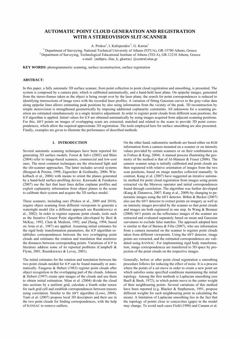
2. POINT CLOUD GENERATION Our scanning system has been presented in Prokos et al. (2009, 2010). Here its main features are outlined. It consists of a pair of web cameras in a fixed relative position and a hand-held laser plane generator, which helps establish point correspondences by coding the scene. The camera system is calibrated automatically using stereo pairs of a planar chessboard pattern. Nodes are ex-tracted using the Harris operator and ordered with the help of a red chess square. System geometry (namely, camera parameters and scaled relative orientation) is found by bundle adjustment. For scanning, stereo pairs are continuously taken from each po-sition of the static camera pair as the laser plane is being slowly swept manually over the object surface. Optionally, the object is placed at the intersection of two (unknown) background planes. Hence, synchronized frames capture the object, the background planes and the laser trace (Fig. 1). The latter is isolated on each frame by subtracting a background reference frame (produced using a temporal median approach). Eventually these reference frames are used for supplying point clouds with photo-texture, but also for automatic initialization of the ICP algorithm as dis-cussed later. All frames then undergo a noise reduction process and are transformed with their stereo mates to epipolar pairs.
Figure 1. A typical stereo pair used in the scanning process. Homologue points are found as intersections of the laser profile with (epipolar) image lines, which represents a peak detection task. Several peak detection approaches are found in literature (Fisher & Naidu, 1996). Here, a Gaussian curve is fitted directly to the intensity values of each row. To relax the strictness of 1D interpolation, two further Gaussian curves with common peak position are simultaneously adapted in the directions of the two main diagonals through the initial peak estimation. In this way,
estimated peaks remain on the epipolar lines, but are influenced also by gray values from the surroundings of the initial estima-tion. This appears to allow better peak localization (≤0.1 pixels); consequently, peaks showing large a posteriori errors in curve fitting can be safely excluded from 3D reconstruction. The parallax equations applied to epipolar images yield 3D co-ordinates without redundancy. Reliability is enhanced by intro-ducing extra geometric constraints. Thus, all 3D points obtained from a single laser profile are bound to be coplanar (on the laser plane). Also, points on a background plane must simultaneously satisfy its equation (this constraint is optional). Third, all neigh-bouring reconstructed 3D points have to be close to each other (neighbours are identified by means of a window in one of the cameras). These constraints introduce significant redundancy in the adjustment, thereby allowing higher accuracy and reliability. Prior to object scanning the background planes must be scanned to provide estimates for their equation coefficients. On the other hand, initial values for all 3D point coordinates are given by the parallax equations, which allow finding approximations for the coefficients of the laser planes. It is then possible to classify all points in three groups (on background planes and on the object). Next, a single iterative 3D reconstruction adjustment is carried out. All laser traces imaged from a particular viewpoint are ad-justed together, with individual points forced to belong to their (unknown) laser plane, while points on background planes are also constrained to lie on the (unknown) corresponding plane. Hence, unknowns include the X and Z coordinates of all points (the Y coordinate is constrained by epipolar geometry) of the N profiles plus 3×N coefficients of the laser planes plus 6 coeffi-cients of the background planes (these are common unknowns for all laser profiles). It is noted that, in order to have more and better distributed observations on background planes, images of the planes alone (without the object) are also included in the ad-justment. Finally, an additional optional step is to back-project all 3D surface points onto the reference images for interpolating colour values which complement the 3D data to allow visualiza-tion of a textured XYZ–RGB set.
3. POINT CLOUD REGISTRATION Scans from different view-points (for each new scan the object is rotated and/or translated against the stationary camera pair) are registered to each other via the ICP algorithm. Approximate values for initialization of ICP are obtained by exploiting texture information from the reference stereo pairs as follows. The fact that the overlap among adjacent point clouds is sufficient for the application of ICP also means that on the respective reference images a substantial overlap exists between the two scans. Each individual point cloud is expressed in the 3D system of the left camera; furthermore, the fixed geometry of the camera pair is known. Therefore, if the orientation of any of the two cameras of a scanning position with respect to any of the two cameras of an adjacent scanning position is found, good initial values for point cloud registration would be available. If, furthermore, the overlapping object area has sufficient texture to allow extraction of SIFT points (Lowe, 2004), their descriptors allow establishing image point homologies. These are then refined using RANSAC (Fischler & Bolles, 1981, Hartley & Zisserman, 2000) to satisfy the epipolar geometry of the stereo pair, i.e. only inlying corres-pondences of the fundamental matrix of the image pair (or its essential matrix since camera geometry is known) are kept. Of course, extracted SIFT points may refer not only to the object surface but also to the background planes. From the scanning
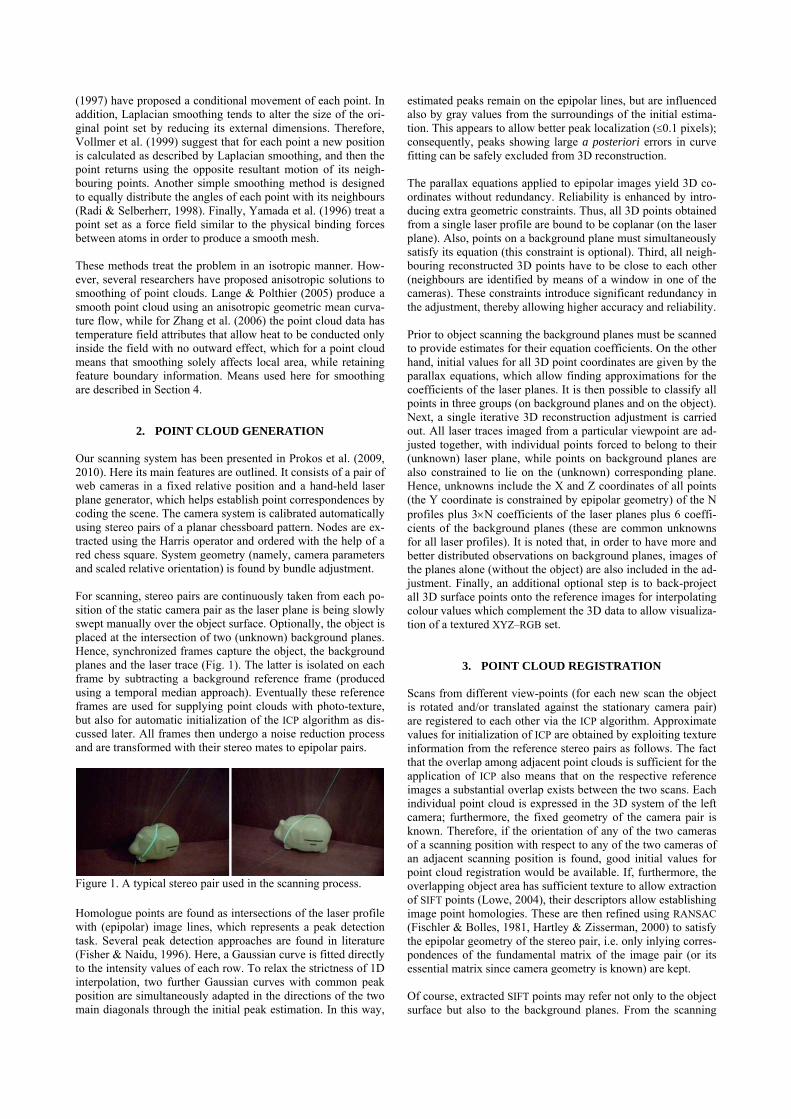
process, background images of the two exterior planes and the object from each scanning position are available. By subtracting these images, thresholding the result and successively applying erosion, dilation and closing operations, the silhouette of the ob-ject emerges (Fig. 2). This region serves as a mask for extracted points, i.e. only points inside it may participate in determining the registration parameters of the two images (strictly speaking, of the two point clouds). Obviously, points may also be detected in the shadow cast by the object (Fig. 2). In our implementation, all four possible combinations of the images of adjacent stereo pairs are checked to find the best solution. If the two left or the two right images of adjacent pairs are used, the matched points in the shadow will have practically the same image coordinates and may be directly excluded; else, it is expected that such out-liers will be detected in the RANSAC process.
Figure 2. Above: reference image (left) and background planes (right). Below: subtraction of these images (left) and silhouette of the object (right), which includes its shadow. To the actual problem of finding initial values for point cloud registration there are two possible approaches. First, the rotation and translation extracted linearly (from the fundamental or the essential matrix) can be refined iteratively in a relative orienta-tion adjustment and then used for point cloud registration. The scale factor can be estimated by extending 2D point homologies to 3D space (the relation between images and scanned object is known) and comparing distances in stereo model and scans. Yet this process appears to be error-prone. While rotation between clouds is adequately estimated, translation may be incorrect due to noisy estimation of scale. Alternatively, the translation can be directly calculated from the center-weights of the corresponding 3D point sets. A straightforward approach adopted here relies directly on rigid body transformation; matched imaged points simply serve as an intermediate step towards finding 3D homologies. This is done by using in a window around a matched image point all known 2D–3D correspondences to interpolate the 3D point. Rigid body transformation is solved linearly (Arun et al., 1987) and refined iteratively. Thus, ≥3 SIFT point correspondences must be trans-ferred to 3D. In some cases image points cannot be upgraded to 3D due to occlusions or because they are in object regions not scanned (scanning needs a threefold visibility, i.e. from both cameras and the laser plane). If needed, therefore, the previous approach is used, which requires only one 3D point correspon-dence for the translation. Of course, both approaches require ≥7 image point homologies for the fundamental matrix, yet it is not necessary for all but one of the 2D correspondences for the first approach, and three for the second, to be upgraded to 3D space.
Our scanner with two cameras allows the creation of four stereo pairs between two scan positions. In a typical case, for instance, where the next position is a result of a clockwise rotation of the object, the stereo pair most suitable for establishing homologies is that of the right image of the first scan and the left image of the second scan. However, the procedure is also performed for the other three possible stereo pairs and, if correspondences are found, the averaged translation and rotation calculated from all are used as initial approximations for ICP.
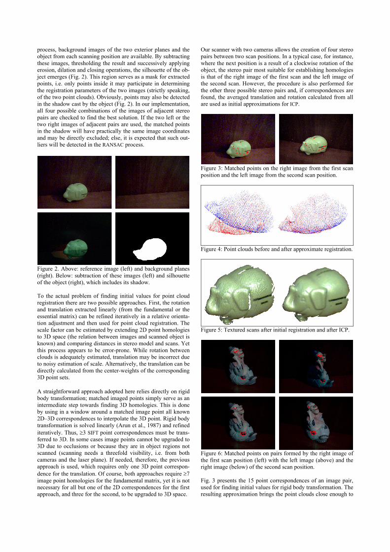
Figure 3: Matched points on the right image from the first scan position and the left image from the second scan position.
Figure 4: Point clouds before and after approximate registration.
Figure 5: Textured scans after initial registration and after ICP.
Figure 6: Matched points on pairs formed by the right image of the first scan position (left) with the left image (above) and the right image (below) of the second scan position. Fig. 3 presents the 15 point correspondences of an image pair, used for finding initial values for rigid body transformation. The resulting approximation brings the point clouds close enough to
each other (Fig. 4) to allow ICP to function. Fig. 5 illustrates the triangulated surface after approximate registration and after ICP has been carried out.
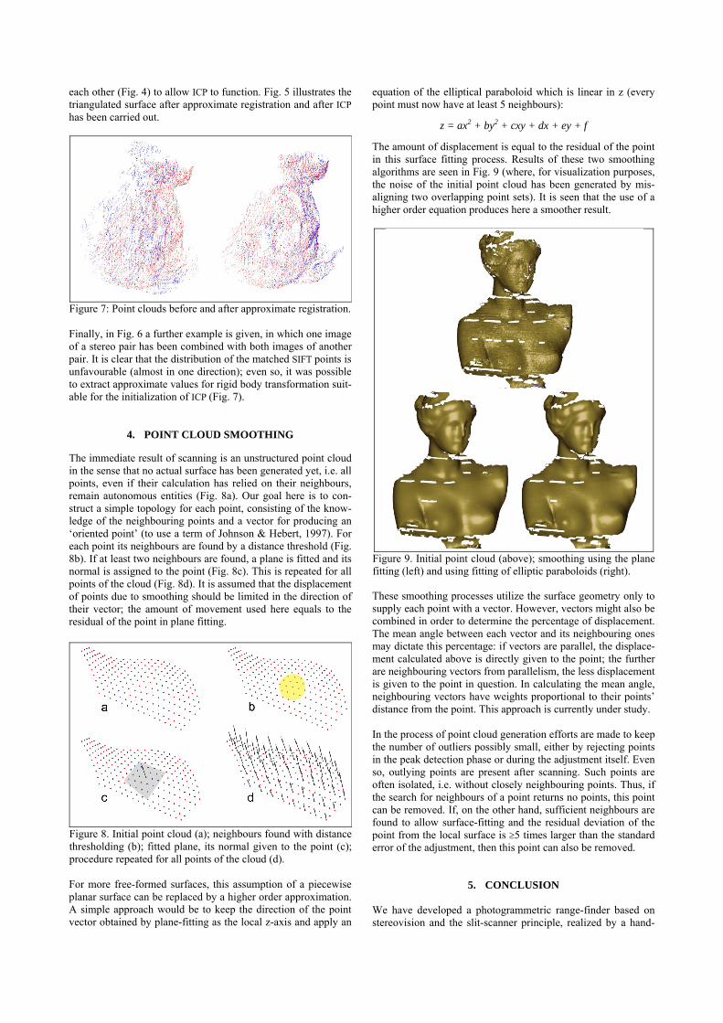
Figure 7: Point clouds before and after approximate registration. Finally, in Fig. 6 a further example is given, in which one image of a stereo pair has been combined with both images of another pair. It is clear that the distribution of the matched SIFT points is unfavourable (almost in one direction); even so, it was possible to extract approximate values for rigid body transformation suit-able for the initialization of ICP (Fig. 7).
4. POINT CLOUD SMOOTHING
The immediate result of scanning is an unstructured point cloud in the sense that no actual surface has been generated yet, i.e. all points, even if their calculation has relied on their neighbours, remain autonomous entities (Fig. 8a). Our goal here is to con-struct a simple topology for each point, consisting of the know-ledge of the neighbouring points and a vector for producing an ‘oriented point’ (to use a term of Johnson & Hebert, 1997). For each point its neighbours are found by a distance threshold (Fig. 8b). If at least two neighbours are found, a plane is fitted and its normal is assigned to the point (Fig. 8c). This is repeated for all points of the cloud (Fig. 8d). It is assumed that the displacement of points due to smoothing should be limited in the direction of their vector; the amount of movement used here equals to the residual of the point in plane fitting.
Figure 8. Initial point cloud (a); neighbours found with distance thresholding (b); fitted plane, its normal given to the point (c);procedure repeated for all points of the cloud (d). For more free-formed surfaces, this assumption of a piecewise planar surface can be replaced by a higher order approximation. A simple approach would be to keep the direction of the point vector obtained by plane-fitting as the local z-axis and apply an
equation of the elliptical paraboloid which is linear in z (every point must now have at least 5 neighbours):
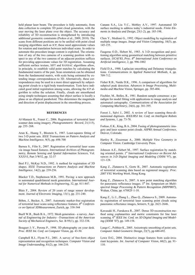
z = ax2 + by2 + cxy + dx + ey + f The amount of displacement is equal to the residual of the point in this surface fitting process. Results of these two smoothing algorithms are seen in Fig. 9 (where, for visualization purposes, the noise of the initial point cloud has been generated by mis-aligning two overlapping point sets). It is seen that the use of a higher order equation produces here a smoother result.
Figure 9. Initial point cloud (above); smoothing using the plane fitting (left) and using fitting of elliptic paraboloids (right). These smoothing processes utilize the surface geometry only to supply each point with a vector. However, vectors might also be combined in order to determine the percentage of displacement. The mean angle between each vector and its neighbouring ones may dictate this percentage: if vectors are parallel, the displace-ment calculated above is directly given to the point; the further are neighbouring vectors from parallelism, the less displacement is given to the point in question. In calculating the mean angle, neighbouring vectors have weights proportional to their points’ distance from the point. This approach is currently under study. In the process of point cloud generation efforts are made to keep the number of outliers possibly small, either by rejecting points in the peak detection phase or during the adjustment itself. Even so, outlying points are present after scanning. Such points are often isolated, i.e. without closely neighbouring points. Thus, if the search for neighbours of a point returns no points, this point can be removed. If, on the other hand, sufficient neighbours are found to allow surface-fitting and the residual deviation of the point from the local surface is ≥5 times larger than the standard error of the adjustment, then this point can also be removed.
5. CONCLUSION We have developed a photogrammetric range-finder based on stereovision and the slit-scanner principle, realized by a hand-
held planar laser beam. The procedure is fully automatic, from data collection to complete 3D point cloud generation, with the user moving the laser plane over the object. The accuracy and reliability of 3D reconstruction is strengthened by introducing additional geometric constraints (Prokos et al., 2009, 2010). The scans from different positions are to be unified with point cloud merging algorithms such as ICP; these need approximate values for rotation and translation between individual scans. In order to automate this procedure image content is exploited. The orienta-tion of any of the two cameras of a scanning position with re-spect to any of the two cameras of an adjacent position suffices for providing approximate values for 3D registration. Assuming sufficient surface texture, SIFT and RANSAC algorithms allow, in principle, to establish valid point matches by calculating the fundamental matrix of the pair. Scan orientation can be obtained from the fundamental matrix, with scale being estimated by ex-tending image correspondences to 3D. Alternatively, these cor-respondences may be used in a more direct approach by subject-ing point clouds to a rigid body transformation. Tests have indi-cated good initial registration among scans, allowing the ICP al-gorithm to refine the solution. Finally, clouds are smoothened using simple techniques assuming that object surface is locally a plane or an elliptical paraboloid. This determines the magnitude and direction of point displacement in the smoothing process.
REFERENCES Al-Manasir K., Fraser C., 2006. Registration of terrestrial laser scanner data using imagery. Photogrammetric Record, 21(115), pp. 255–268. Arun K., Huang T., Blostein S., 1987. Least-squares fitting of two 3-D point sets. IEEE Transactions on Pattern Analysis and Machine Intelligence, 9(5), pp. 698-700 Barnea S., Filin S., 2007. Registration of terrestrial laser scans via image based features. International Archives of Photogram-metry, Remote Sensing and Spatial Information Sciences, Vol. XXXVI, Part 3/W52, pp. 32-37 Besl P.J., McKay N.D., 1992. A method for registration of 3D shapes. IEEE Transactions on Pattern Analysis and Machine Intelligence, 14(2), pp. 239-256. Blacker T.D., Stephenson M.B., 1991. Paving: a new approach to automated quadrilateral mesh generation. International Jour-nal for Numerical Methods in Engineering, 32, pp. 811-847. Blais F., 2004. Review of 20 years of range sensor develop-ment. Journal of Electronic Imaging, 13(1), pp. 231-240. Böhm, J., Becker, S., 2007. Automatic marker-free registration of terrestrial laser scans using reflectance features. 8th Conferen-ce on Optical 3DMeasurement, Zurich, pp. 338-344 Buell W.R., Bush B.A., 1972. Mesh generation - a survey. Jour-nal of Engineering for Industry –Transactions of the American Society of Mechanical Engineers, Ser. B 95(1), pp. 332-338. Bouguet J.-Y., Perona P., 1998. 3D photography on your desk. Proc. IEEE Int. Conf. on Computer Vision, pp. 43-50. Campbell R.J., Flynn P.J., 2001. A survey of free-form object representation and recognition techniques. Computer Vision and Image Understanding, 81(2), pp. 166-210.
Canann S.A., Liu Y.C., Mobley A.V., 1997. Automated 3D surface meshing to address today’s industrial needs. Finite Ele-ments in Analysis and Design, 25(1-2), pp. 185-198. Chen Y., Medioni G., 1992. Object modelling by registration of multiple range images. Image and Vision Computing, 10(3), pp. 145-155. Faugeras O.D., Hebert M., 1983. A 3-D recognition and posi-tioning algorithm using geometrical matching between primitive surfaces. IJCAI’83, Proc. 8th International Joint Conference on Artificial intelligence, 2, pp. 996-1002 Field D.A., 1988. Laplacian smoothing and Delaunay triangula-tions. Communications in Applied Numerical Methods, 4, pp. 709-712. Fisher R.B., Naidu D.K., 1996. A comparison of algorithms for subpixel peak detection. Advances in Image Processing, Multi-media and Machine Vision, Springer, pp. 385-404. Fischler, Μ., Bolles, R., 1981. Random sample consensus: a pa-radigm for model fitting with applications to image analysis and automated cartography. Communications of the Association for Computing Machinery, 24(6), pp. 381-395. Forest J., Salvi J., 2002. A review of laser scanning three-di-mensional digitisers. IEEE/RSJ Int. Conf. on Intelligent Robots and Systems, 1, pp. 73-78. Forkuo, E.K., King, B.A., 2004. Fusing of photogrammetric ima-gery and laser scanner point clouds. ASPRS Annual Conference, Denver, Colorado. Hartley R., Zisserman A., 2000. Multiple View Geometry in Computer Vision. Cambridge University Press. Johnson A.E., Hebert M., 1997. Surface registration by match-ing oriented points. 1st International Conference on Recent Ad-vances in 3-D Digital Imaging and Modeling (3DIM '97), pp. 121-128. Kang Z., Zlatanova S., Gorte B., 2007. Automatic registration of terrestrial scanning data based on registered imagery. Proc. 2007 FIG Working Week, Hong Kong. Kang Z., Zlatanova S., 2007. A new point matching algorithm for panoramic reflectance images. 5th Int. Symposium on Multi-spectral Image Processing & Pattern Recognition (MIPPR07), Wuhan, China, pp. 67882F-1-10. Kang Z., Li J., Zhang L., Zhao Q., Zlatanova S., 2009. Automa-tic registration of terrestrial laser scanning point clouds using panoramic reflectance images, Sensors, 9, pp. 2621-2646. Kawasaki H., Furukawa R., 2007. Dense 3D reconstruction me-thod using coplanarities and metric constraints for line laser scanning. 6th IEEE Int. Conf. on 3D Digital Imaging and Model-ing (3DIM ’07), pp. 149-158. Lange C., Polthier K., 2005. Anisotropic smoothing of point sets. Computer Aided Geometric Design, 22(7), pp 680-692. Lowe D.G., 2004. Distinctive image features from scale-inva-riant keypoints. Int. Journal of Computer Vision, 60(2), pp. 91-110.

Mian A., Bennamoun M., Owens R., 2004. Tensors for automa-tic correspondence and registration. Proc. ECCV 2004, Lecture Notes in Computer Science, Springer, Vol. 3022, pp. 495-505. Prokos A., Karras G., Grammatikopoulos L., 2009. Design and evaluation of a photogrammetric 3D surface scanner. Proc. 22nd CIPA Symposium, October 11-15, Kyoto, Japan. Prokos A., Karras G., Petsa E., 2010. Automatic 3D surface re-construction by combining stereovision with the slit-scanner approach. International Archives of Photogrammetry, Remote Sensing and Spatial Information Sciences, Vol. XXXVIII, Part 5, pp. 505-509. Radi M., Selberherr S., 1998. Three-dimensional adaptive mesh relaxation.. Int. Conference on Simulation of Semiconductor De-vices and Processes, pp. 193-196 Rusinkiewicz S., Levoy M., 2001. Efficient variants of the ICP algorithm. International Conference on 3D Digital Imaging and Modeling (3DIM), pp. 145–152. Rusinkiewicz S., Hall-Holt O., Levoy M., 2002. Real-time 3D model acquisition. ACM Transactions on Graphics, 21(3), pp. 438-446. Taati B., Bondy M., Jasiobedzki P., Greenspan M., 2007. Au-tomatic registration for model building using variable dimensional local shape descriptors. 6th Int. Conference on 3D Digital Imaging and Modeling (3DIM 2007), pp. 265-272.
Vollmer J., Mencl R., Müller H., 1999. Improved laplacian smoothing of noisy surface meshes. Computer Graphics Forum, 18(3), pp. 131–138. Wang Z., Brenner C., 2008. Point based registration of terrestri-al laser data using intensity and geometry features. International Archives of the Photogrammetry, Remote Sensing and Spatial Information Sciences. Vol. XXXVII, Part B5, pp. 583-589. Winkelbach S., Molkenstruck S., Wahl F.M., 2006. Low-cost laser range scanner and fast surface registration approach. Proc. DAGM ’06, Lecture Notes in Computer Science, Vol. 4174, Springer, pp. 718–728. Yamada A., Shimada K., Itoh T., 1996. Energy-minimizing ap-proach to meshing curved wire-frame models. 5th International Meshing Roundtable, pp. 179-191. Zagorchev L., Goshtasby A.A., 2006. A paint-brush laser range scanner. Computer Vision & Image Understanding, 101, pp. 65-86. Zhang X., Xi J., Yan J., 2006. A methodology for smoothing of point cloud data based on anisotropic heat conduction theory. International Journal of Advanced Manufacturing Technology, 30(1-2), pp.70-75. Zhang Z., 1994. Iterative point matching for registration of free-form curves and surfaces. International Journal of Computer Vision, 13(2), pp. 119-152.