Embed Size (px)
Citation preview
Operator & Parts Manual
A
uto
ma
tic
Sc
rub
be
r
www.icecompanies.com
8210060 REV.04 (12-2015)
i28BT i32BT
INTERNATIONAL CLEANING EQUIPMENT
2 ICE i28BT / i32BT
OPERATOR MANUAL
HOW TO ORDER PARTS Only use ICE Company supplied or equivalent parts. Parts and supplies may be ordered online,by phone, by fax or by mail.1. Identify the machine model.2. Identify the machine serial number from the data label.3. Ensure the proper serial number is used from the parts list.4. Identify the part number and quantity. Do not order by page or reference numbers.5. Provide your name, company name, customer ID number,billing and shipping address, phone number and purchase order number.
Please fill out at time of installation for future reference.Model No. Serial No. Machine Options Sales Rep. Sales Rep. Phone No. Customer ID Number Installation Date
READ OPERATOR MANUAL CAREFULLY!
International Cleaning EquipmentXiangShi Road LiaoBu DongGuan GuangDong ChinaTel: 0769 - 81850061Fax:0769 - 81850001
Specifications and parts are subject to change without notice.
IMPORTANT: To ensure full warranty protection, please fill out & return your warranty card.
PROTECT THE ENVIRONMENTPlease dispose of packaging materials,old machine components such as batteries, hazardous fluids, including antifreeze and oil, in an environmentally safe way according to local waste disposal regulations.
Always remember to recycle.

ICE i28BT / i32BT 3
OPERATOR MANUAL
SAFETY PROCATIONS.......................................................................................................4
MACHINE COMPONENTS...................................................................................................5
MACHINE SETUP & INSTALLATION....................................................................................6
MACHINE OPERATION.................................................................................................7
WHILE OPERATING MACHINE..........................................................................................7
TANK DRAINING..................................................................................................................8
BATTERY CHARGING.........................................................................................................9
PREVENTATIVE MAINTENANCE.......................................................................................9
BASIC TROUBLESHOOTING............................................................................................11
TECHNICAL SPECIFICATION............................................................................................12
PARTS LIST...................................................................................................................13-34
WEAR AND TEAR PARTS..................................................................................................35
WIRING DIAGRAM.............................................................................................................36
TABLE OF CONTENTS / 目录
4 ICE i28BT / i32BT
OPERATOR MANUAL
SAFETY PRECAUTIONS
This machine is intended for commercial use. It is designed exclusively to scrub hard floors in an indoor environment and is not constructed for any other use. Only use recommended accessories.
All operators shall read, understand and exercise the following safety precautions:
1. Do not operate machine: - Unless trained and authorized. - Unless you have read and understand the
operators manual. - In flammable or exploxive areas. - If not in proper operating condition. - In outdoors areas.
2. Before starting machine: - Make sure all safety devices are in place
and operate properly.
3. When using machine: - Go slow on inclines and slippery
surfaces. - Follow all safety guidelines. - Be very careful when using the machine in
reverse. - Reduce speed when turning. - Report and fix any damage to machine prior
to operating it. - Never allow children to play on or
around. - Do not operate on inclines that exceed 5%
(3°).
4. Before leaving or servicing machine: - Stop on level surface. - Turn off machine.
5. When servicing machine: - Read operators manual thoroughly prior to
operating or servicing this machine. - Use manufacturer supplied or approved
replacement parts. - Secure machine with wheel blocks prior to
jacking the machine up. - Use approved jack or hoist to safely elevate
the machine. - Disconnect batteries prior to working on
machine. - Wear gloves when handling batteries or
battery cables.
- Avoid any contact with battery acid - Avoid moving parts. Do not wear loose fitting
clothing while servicing machine.
WARNING: Batteries emit hydrogen gas. Explosion or fire can result from hydrogen gas. Keep sparks and open flames away! Keep battery compartment open when charging.
WARNING: Flammable materials can cause an explosion or fire. Do not use flammable materials in tanks.
WARNING: Flammable materials or reactive metals can cause explosion or fire. Do not pick up.

ICE i28BT / i32BT 5
OPERATOR MANUAL
MACHINE COMPONENTS
1. Control Handle2. Brush pressure adjusting buttons & indicator light Brush pressure increase button Brush pressure decrease button3. Hour meter4. Speed Control Knob Slow Speed Fast Speed5. Battery Meter6. Main Power Key Switch7. 1-STEP scrub head up/down switch & indicator light8. Solution flow Control Buttons & Indicator Light Solution flow Increase button Solution flow Decrease button9. Vacuum Motor Switch & Indicator Light10. Emergency stop button11. Drive motor circuit breaker12. Solution Tank Level / Drain Hose13. On-board battery charger14. Caster, 2Inch, Squeegee Adjustment15. Bumper Rollers16. Squeegee Assembly17. Ball Valve
18. Casters, 4 Inch19. Squeegee Vacuum Hose20. Filter Assembly21. Wheels, 8 Inch22. Recovery Tank Drain Hose23. Hose fill-port24. Squeegee Lift Lever25. Control Handle Start Bail Direction Decal26. Batteries27. Recovery Tank Support Stand28. Vacuum Motor, 24VDC29. Cup Holder30. Recovery Tank Cover31. Recovery Tank32. ICE Logo33. Vacuum motor circuit breaker34. Bucket Fill Port/ Clean-Out Port35. Solution Tank36. LED Light37. Front cover 38. Brush & Pad realease plunger39. Scrub Head adjusting bolt40. Scrub Head Skirt41. Scrub Head Assembly42. Parking Brake (Option)
3 2554 6
8
9
10
11
12
13
15161718192021
22
23
24
26 27 28
30
31
32
33
35
37
+-
7 29
36
21
14 38 39 40 41
+-
34
42
6 ICE i28BT / i32BT
OPERATOR MANUAL
UNCRATING MACHINEBe sure and check packing carton for any damage. Immediately report any damage to carrier. Check the contents of package to ensure that the following items are included:
• Machine• 4-6V Batteries• Squeegee assembly• 2-Pad Drivers• 2-Brushes
INSTALLING BATTERIES
The batteries are already in the machine upon delivery; However you will need to connect the cables to the battery posts.
WARNING: Batteries emit hydrogen gas.Explosion or fire can result from hydrogen gas.Keep sparks and open flames away! Keep battery compartment open when charging.
Recommended Battery spec:4-6V, 260AH@20HR deep cycle batteries. Max. batteries dimensions :265mm (L) X 190mm (W) X 280mm (H)
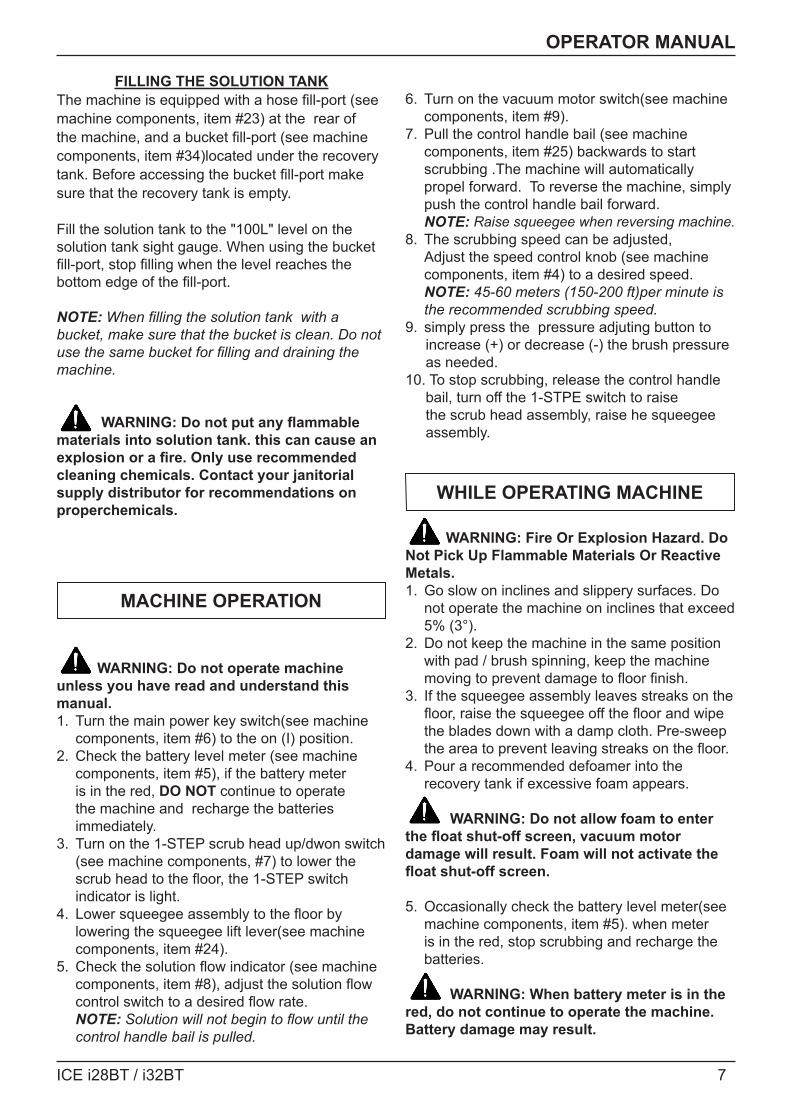
1. Turn the main power key switch off.2. Open recovery tank to gain access to battery
compartment.3. Carefully place the batteries into the
compartment as shown in figure below. Place the battery brace at the rear of the batteries. DO NOT DROP BATTERIES INTO COMPARTMENT!
4. Connect battery cables to posts in numbered order as shown in drawing below. RED to POSITIVE and BLACK to NEGATIVE.
MACHINE SET UP
PRE-OPERATION CHECKS1. Sweep or dust mop the surface to be cleaned.2. Check battery meter to make sure batteries are
fully charged. (See BATTERY CHARGING)3. Check that squeegee is properly installed.4. Check that brushes / pads is properly installed.
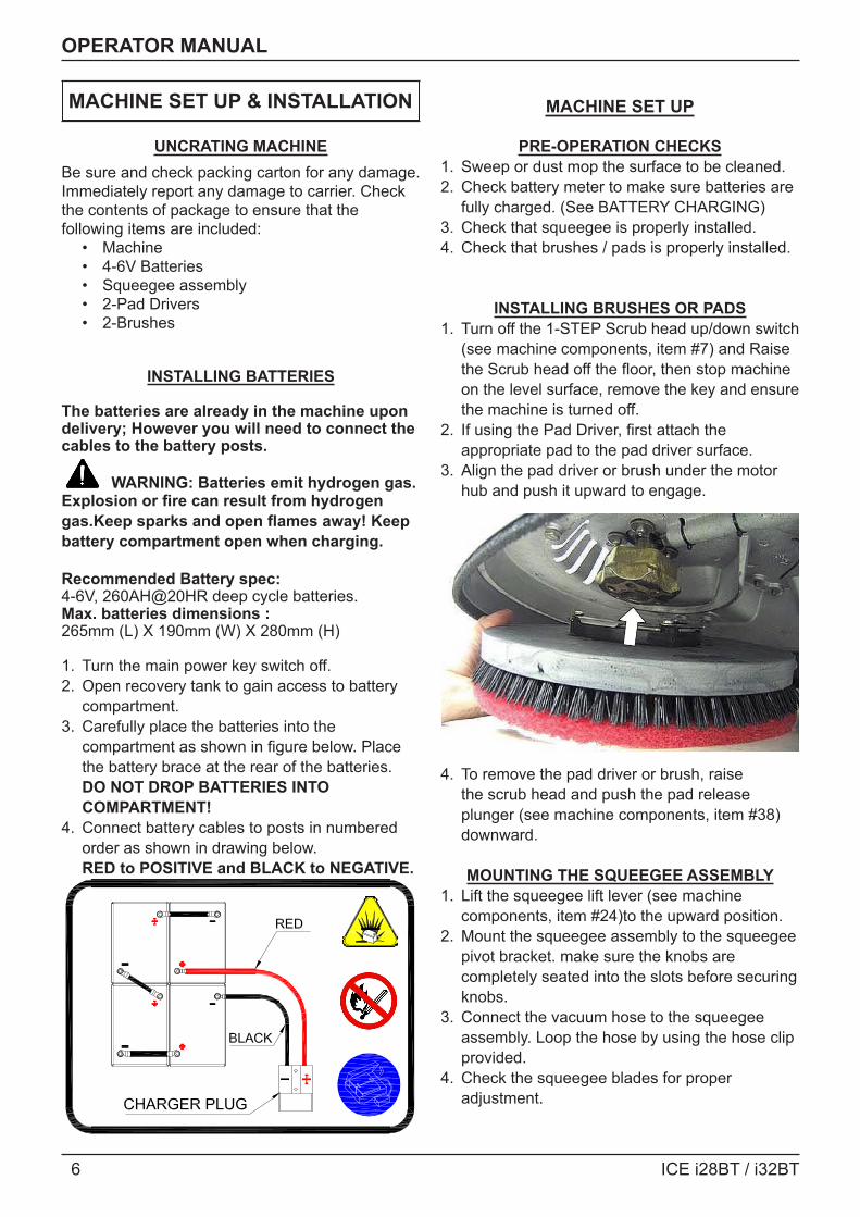
INSTALLING BRUSHES OR PADS1. Turn off the 1-STEP Scrub head up/down switch
(see machine components, item #7) and Raise the Scrub head off the floor, then stop machine on the level surface, remove the key and ensure the machine is turned off.
2. If using the Pad Driver, first attach the appropriate pad to the pad driver surface.
3. Align the pad driver or brush under the motor hub and push it upward to engage.
4. To remove the pad driver or brush, raise the scrub head and push the pad release plunger (see machine components, item #38) downward.
MOUNTING THE SQUEEGEE ASSEMBLY1. Lift the squeegee lift lever (see machine
components, item #24)to the upward position.2. Mount the squeegee assembly to the squeegee
pivot bracket. make sure the knobs are completely seated into the slots before securing knobs.
3. Connect the vacuum hose to the squeegee assembly. Loop the hose by using the hose clip provided.
4. Check the squeegee blades for proper adjustment.
MACHINE SET UP & INSTALLATION
ICE i28BT / i32BT 7
OPERATOR MANUAL
FILLING THE SOLUTION TANKThe machine is equipped with a hose fill-port (see machine components, item #23) at the rear of the machine, and a bucket fill-port (see machine components, item #34)located under the recovery tank. Before accessing the bucket fill-port make sure that the recovery tank is empty.
Fill the solution tank to the "100L" level on the solution tank sight gauge. When using the bucket fill-port, stop filling when the level reaches the bottom edge of the fill-port.
NOTE: When filling the solution tank with a bucket, make sure that the bucket is clean. Do not use the same bucket for filling and draining the machine.
WARNING: Do not put any flammable materials into solution tank. this can cause an explosion or a fire. Only use recommended cleaning chemicals. Contact your janitorial supply distributor for recommendations on properchemicals.
WARNING: Do not operate machine unless you have read and understand this manual.1. Turn the main power key switch(see machine
components, item #6) to the on (I) position.2. Check the battery level meter (see machine
components, item #5), if the battery meter is in the red, DO NOT continue to operate the machine and recharge the batteries immediately.
3. Turn on the 1-STEP scrub head up/dwon switch (see machine components, #7) to lower the scrub head to the floor, the 1-STEP switch indicator is light.
4. Lower squeegee assembly to the floor by lowering the squeegee lift lever(see machine components, item #24).
5. Check the solution flow indicator (see machine components, item #8), adjust the solution flow control switch to a desired flow rate. NOTE: Solution will not begin to flow until the control handle bail is pulled.
6. Turn on the vacuum motor switch(see machine components, item #9).
7. Pull the control handle bail (see machine components, item #25) backwards to start scrubbing .The machine will automatically propel forward. To reverse the machine, simply push the control handle bail forward. NOTE: Raise squeegee when reversing machine.
8. The scrubbing speed can be adjusted, Adjust the speed control knob (see machine components, item #4) to a desired speed. NOTE: 45-60 meters (150-200 ft)per minute is the recommended scrubbing speed.
9. simply press the pressure adjuting button to increase (+) or decrease (-) the brush pressure as needed. 10. To stop scrubbing, release the control handle bail, turn off the 1-STPE switch to raise the scrub head assembly, raise he squeegee assembly.
WARNING: Fire Or Explosion Hazard. Do Not Pick Up Flammable Materials Or Reactive Metals.1. Go slow on inclines and slippery surfaces. Do
not operate the machine on inclines that exceed 5% (3°).
2. Do not keep the machine in the same position with pad / brush spinning, keep the machine moving to prevent damage to floor finish.
3. If the squeegee assembly leaves streaks on the floor, raise the squeegee off the floor and wipe the blades down with a damp cloth. Pre-sweep the area to prevent leaving streaks on the floor.
4. Pour a recommended defoamer into the recovery tank if excessive foam appears.
WARNING: Do not allow foam to enter the float shut-off screen, vacuum motor damage will result. Foam will not activate the float shut-off screen.
5. Occasionally check the battery level meter(see machine components, item #5). when meter is in the red, stop scrubbing and recharge the batteries.
WARNING: When battery meter is in the red, do not continue to operate the machine. Battery damage may result.
MACHINE OPERATION
WHILE OPERATING MACHINE

8 ICE i28BT / i32BT
OPERATOR MANUAL
6. When the solution tank runs empty, press the 1-STEP switch raise the brush head. Keep the squeegee down and continue to vacuum until all the dirty water is picked up. NOTE: Brush motors will not work when the scrub head assembly raised.
NOTE: See TANK DRAINING section to learn how to drain recovery and solution tanks. CIRCUIT BREAKER / FUSES The machine is equipped with 2 resettable circuit breakers(see machine components, item #11, item# 33) to protect the drive motor and the vacuum motor from damage. If the circuit breakers should trip, it can't be reset immediately. You must first determine what caused the breaker to trip, and allow the motor to cool down and then you can manually reset the circuit breakers. The machine is also equipped with a 60A fuse to protect the brush motors from damage. When replacing a fuse never substitute a higher Amps rated fuse than specified. HOUR METER The hour meter (see machine components, item #3) records the number of total hours the brush motor has been powered on. Use the hour meter to determine when to perform recommended maintenance procedures and to record service history.
EMERGENCY STOP BUTTON/ BRAKEThe machine is equipped with an Electromagnetic Brake Mechanism on the Transaxle. When in case of Emergency, release the Control Handle bail(see machine components, item #25) or strike the Emergency stop button (see machine components, item #10), the machine will be braked and then stop. Reset the emergency stop button, turn on the Main power key switch, and then pull the control handle bail, the machine will be restart.
NOTE: The machine can not be moved unless the Main Power Key Switch and the Control Handle bail be turned on. WARNING: Do Not Change the Default Settings of the Electromagnetic Brake Mechanism unless Authorized, otherwise it may cause Machine Damage or Personal Injury. Contact the Authorized Service center for machine repairs.
1. Turn the machine off.2. With the squeegee and scrub head in their "up"
position, transport machine to approved area for draining tank(s).
DRAINING THE RECOVERY TANKAny time scrubbing is completed, or when refilling solution tank, the recovery tank should be drained and cleaned. WARNING: If the recovery tank is not drained when the solution tank has been refilled, foam or water may enter the float shut-off screen and cause damage to the vacuum motor.
1. While holding the drain hose (see machine components, item #22) upward, remove the cap and lower hose to drain.
2. Open the recovery tank cover and rinse out the tank. Use a rag to remove any excess dirt.
3. Clean the float shut-off screen and debris tray located in the recovery tank .
DRAINING THE SOLUTION TANKAny time scrubbing operation is completed, the solution tank should be drained and cleaned.1. Pull the solution tank level hose(see machine
components, item #12) off the hose fitting, this will allow the solution to flow freely into a bucket or floor drain.
2. Remove the cover of the filter assembly(see machine components, item #20) to drain the solution tank, check the filter screen and clean up it if necessary.
3. Rinse the solution tank with clean water after every use. This will help prevent chemical buildup and clogging of the solution lines.
4. After rinsing out the tank, securely reconnect the tank level hose to the hose fitting, replace the filter assembly cover and be sure the filter screen and the "O" ring is in the correct position.
TANK DRAINING
ICE i28BT / i32BT 9
OPERATOR MANUAL
BATTERY CHARGING
WARNING: Fire Or Explosion Hazard.Batteries Emit Hydrogen Gas. Keep Sparks andOpen Flame Away. Keep Battery CompartmentPropped Open When Charging. NOTE: Use only apprved chargers with the following specifications:• Automatic shut off circuit• Deep cycle charging• Output current of 20-30 Amps• Output voltage of 24 volts
ON-BOARD BATTERY CHARGERAs standard configuration, the machine is equiped with the On-board battery charger (see machine components, item #13). The settings of On-board battery charger had been set for the recommended batteries type.
WARNING: The On-board battery charger setting's change are to be completed by authorized service centers only. Failure to properly set will result in the batteries or charger damage.
1. Transport the machine to a well ventilated area.2. Turn the machine off.3. If charging wet (lead acid) batteries check the
fluid level before charging.4. Prop up the recovery tank by the support
stand (see machine components, item #27) for ventilation.
5. Connect the charger's AC power supply cord to a properly grounded receptable.
6. The charger will automatically begin to charge, once the charging cycle begins, the indicator lights will progress from red, yellow to green. when the green indicator light comes on, the charging cycle is done. Unplug the charger cord. NOTE: The machine will can not operate when charging. OFF-BOARD BATTERY CHARGER (OPTION)
1. Place charger and machine in a well ventilated area.
2. Turn the machine off.
3. If charging wet (lead acid) batteries check the fluid level before charging.
4. Prop up the recovery tank by the support stand (see machine components, item #27) for ventilation.
5. Connect the charger's AC power supply cord to a properly grounded receptable.
6. Connect the charger's DC cord into the machine's battery receptacle at the rear of the machine.
7. The charger will automatically begin to charge and will autoatically shut off once the batteries are fully charged.
8. Upon completion of charging, disconnect the AC power supply cord first, and then disconnect the charger from the machine.
WARNING: Before performing any maintenance on the machine, be sure that the power is turned off, or the batteries are disconnected!
WARING: Repairs are to be completed by Authorized service centers only. Any repairs completed by unauthorized persons will avoid the warrenty.
DAILY MAINTENANCE1. Remove pad driver/ brush and clean with
approved cleaner.2. Drain recovery and solution tanks completely
and rinse out with clean water. Visually check the recovery tank for debris and clean out as necessary.
3. Raise the squeegee assembly off floor and wipe it down with a damp towel. Be sure to store the squeegee in the up position.
4. Remove the float shut-off assembly and rinse it out with clean water.
5. Clean machine with an approved cleaner and a damp towel.
6. Recharge the batteries.7. Check the condition of the squeegee blade
wiping edge, rotate blade if worn.
PREVENTATIVE MAINTENANCE
10 ICE i28BT / i32BT
OPERATOR MANUAL
MONTHLY MAINTENANCE1. Clean the battery tops to prevent corrosion.2. Check for loose battery cable connections.3. Inspect and clean the recovery tank cover seal.
Replce it if damaged.4. Lubricate all grease points and pivot points with
silicon spray and approved grease.5. Check the machine for loose nuts and bolts.6. Check the machine for leaks.
MOTOR MAINTENANCE1. Contact your local Distributor for any motor
maintenance.2. Motor should have the brushes checked every
250 hours. Brushes should be replaced when they are worn to a length of 10 mm or less.
BATTERY MAINTENANCE
WARNING: Batteries emit hydrogen gas and an explosion o fire can result. Keep sparks and fire away from batteries at all times.
WARNING: Whenever serviving batteries, be sure to wear protective gloves. Avoid contact with battery acid at all times.
NOTE: For the best machine performance, keep batteries charged at all times. Do not let them sit in a discharged condition.
1. Always follow the battery charging directions as outlined in the BATTERY CHARGING section of this manual.
2. Keep battery tops and terminals free from corrosion. A strong solution of baking soda and water is the best way to keep the batteries corrosion free. DO NOT ALLOW THE BAKING SODA / WATER SOLUTION TO ENTER THE BATTERY CELLS.
3. Use a wire brush with the baking soda solution to properly clean the battery posts and connctions.
4. Check battery connections for wear and loose terminals. replace if necessary.
MACHINE STORAGE1. Always store the machine indoors.2. Always store the machine in a dry area.3. Always store the machine in its upright position.4. Always store the machine with the pad driver/
brush raised off the floor.5. Always store the machine with the squeegee
assembly raised off the floor.6. If storing in an area which may reach freezing
temperatures, be sure to drain all fluids from the machine prior to storage. Any damage caused by freezing temperatures will not be covered by the warranty.
7. Drain the recovery tank.8. Drain the solution tank of all fluid.
ICE i28BT / i32BT 11
OPERATOR MANUAL
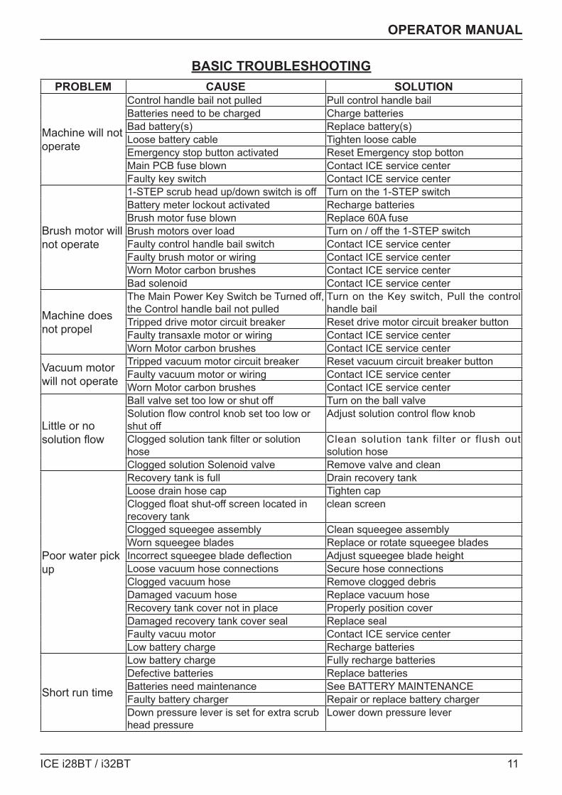
PROBLEM CAUSE SOLUTION
Machine will not operate
Control handle bail not pulled Pull control handle bailBatteries need to be charged Charge batteriesBad battery(s) Replace battery(s)Loose battery cable Tighten loose cableEmergency stop button activated Reset Emergency stop bottonMain PCB fuse blown Contact ICE service centerFaulty key switch Contact ICE service center
Brush motor will not operate
1-STEP scrub head up/down switch is off Turn on the 1-STEP switchBattery meter lockout activated Recharge batteriesBrush motor fuse blown Replace 60A fuseBrush motors over load Turn on / off the 1-STEP switchFaulty control handle bail switch Contact ICE service centerFaulty brush motor or wiring Contact ICE service centerWorn Motor carbon brushes Contact ICE service centerBad solenoid Contact ICE service center
Machine does not propel
The Main Power Key Switch be Turned off, the Control handle bail not pulled
Turn on the Key switch, Pull the control handle bail
Tripped drive motor circuit breaker Reset drive motor circuit breaker buttonFaulty transaxle motor or wiring Contact ICE service centerWorn Motor carbon brushes Contact ICE service center
Vacuum motor will not operate
Tripped vacuum motor circuit breaker Reset vacuum circuit breaker buttonFaulty vacuum motor or wiring Contact ICE service centerWorn Motor carbon brushes Contact ICE service center
Little or no solution flow
Ball valve set too low or shut off Turn on the ball valveSolution flow control knob set too low or shut off
Adjust solution control flow knob
Clogged solution tank filter or solution hose
Clean solution tank filter or flush out solution hose
Clogged solution Solenoid valve Remove valve and clean
Poor water pick up
Recovery tank is full Drain recovery tankLoose drain hose cap Tighten capClogged float shut-off screen located in recovery tank
clean screen
Clogged squeegee assembly Clean squeegee assemblyWorn squeegee blades Replace or rotate squeegee bladesIncorrect squeegee blade deflection Adjust squeegee blade heightLoose vacuum hose connections Secure hose connectionsClogged vacuum hose Remove clogged debrisDamaged vacuum hose Replace vacuum hoseRecovery tank cover not in place Properly position coverDamaged recovery tank cover seal Replace sealFaulty vacuu motor Contact ICE service centerLow battery charge Recharge batteries
Short run time
Low battery charge Fully recharge batteriesDefective batteries Replace batteriesBatteries need maintenance See BATTERY MAINTENANCEFaulty battery charger Repair or replace battery chargerDown pressure lever is set for extra scrub head pressure
Lower down pressure lever
BASIC TROUBLESHOOTING
12 ICE i28BT / i32BT
OPERATOR MANUAL
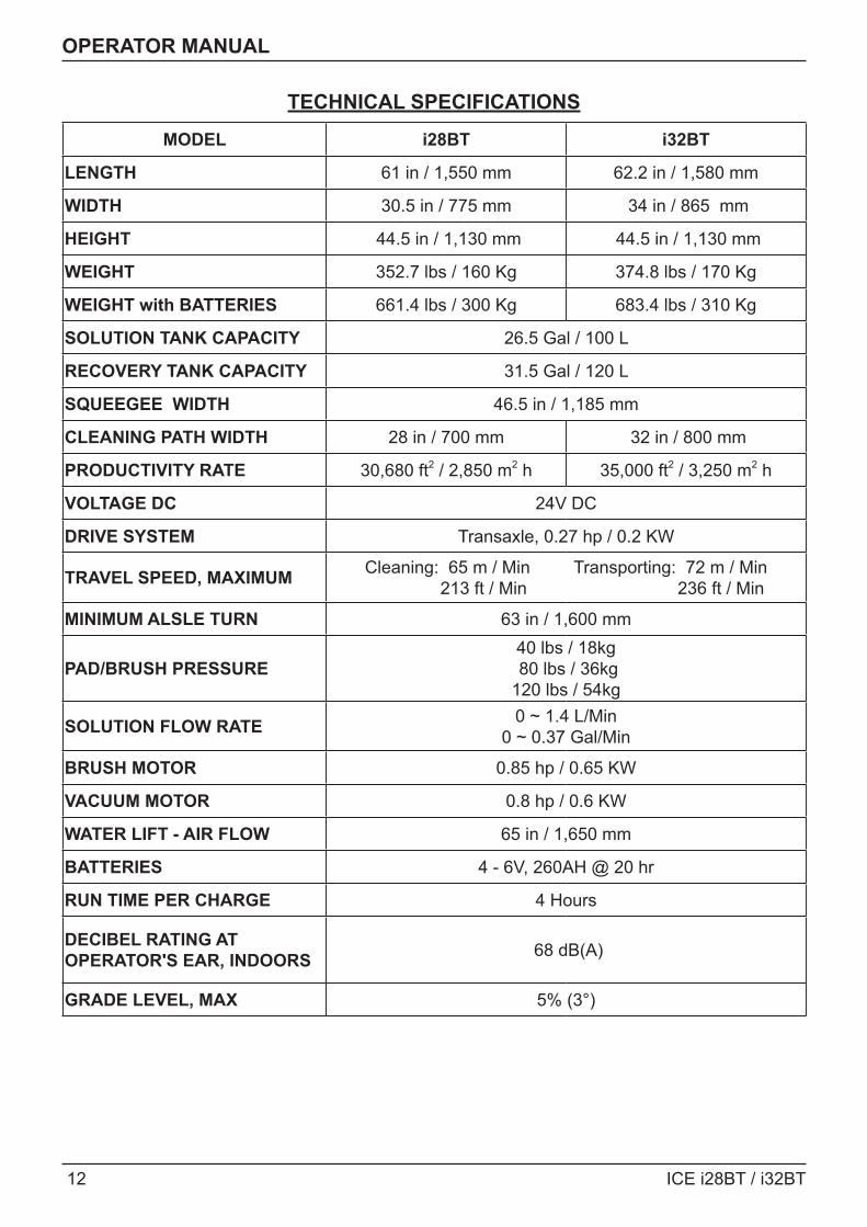
TECHNICAL SPECIFICATIONS
MODEL i28BT i32BT
LENGTH 61 in / 1,550 mm 62.2 in / 1,580 mm
WIDTH 30.5 in / 775 mm 34 in / 865 mm
HEIGHT 44.5 in / 1,130 mm 44.5 in / 1,130 mm
WEIGHT 352.7 lbs / 160 Kg 374.8 lbs / 170 Kg
WEIGHT with BATTERIES 661.4 lbs / 300 Kg 683.4 lbs / 310 Kg
SOLUTION TANK CAPACITY 26.5 Gal / 100 L
RECOVERY TANK CAPACITY 31.5 Gal / 120 L
SQUEEGEE WIDTH 46.5 in / 1,185 mm
CLEANING PATH WIDTH 28 in / 700 mm 32 in / 800 mm
PRODUCTIVITY RATE 30,680 ft2 / 2,850 m2 h 35,000 ft2 / 3,250 m2 h
VOLTAGE DC 24V DC
DRIVE SYSTEM Transaxle, 0.27 hp / 0.2 KW
TRAVEL SPEED, MAXIMUM Cleaning: 65 m / Min Transporting: 72 m / Min 213 ft / Min 236 ft / Min
MINIMUM ALSLE TURN 63 in / 1,600 mm
PAD/BRUSH PRESSURE40 lbs / 18kg 80 lbs / 36kg 120 lbs / 54kg
SOLUTION FLOW RATE 0 ~ 1.4 L/Min 0 ~ 0.37 Gal/Min
BRUSH MOTOR 0.85 hp / 0.65 KW
VACUUM MOTOR 0.8 hp / 0.6 KW
WATER LIFT - AIR FLOW 65 in / 1,650 mm
BATTERIES 4 - 6V, 260AH @ 20 hr
RUN TIME PER CHARGE 4 Hours
DECIBEL RATING AT OPERATOR'S EAR, INDOORS 68 dB(A)
GRADE LEVEL, MAX 5% (3°)
ICE i28BT / i32BT 13
PARTS LIST
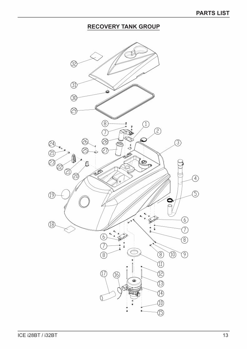
RECOVERY TANK GROUP
14 ICE i28BT / i32BT
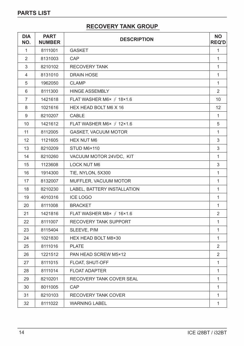
PARTS LIST
RECOVERY TANK GROUP DIA NO.
PART NUMBER DESCRIPTION NO
REQ'D1 8111001 GASKET 1
2 8131003 CAP 1
3 8210102 RECOVERY TANK 1
4 8131010 DRAIN HOSE 1
5 1962050 CLAMP 1
6 8111300 HINGE ASSEMBLY 2
7 1421618 FLAT WASHER M6× ∮ 18×1.6 10
8 1021616 HEX HEAD BOLT M6 X 16 12
9 8210207 CABLE 1
10 1421612 FLAT WASHER M6× ∮ 12×1.6 5
11 8112005 GASKET, VACUUM MOTOR 1
12 1121605 HEX NUT M6 3
13 8210209 STUD M6×110 3
14 8210260 VACUUM MOTOR 24VDC, KIT 1
15 1123608 LOCK NUT M6 3
16 1914300 TIE, NYLON, 5X300 1
17 8132007 MUFFLER, VACUUM MOTOR 1
18 8210230 LABEL, BATTERY INSTALLATION 1
19 4010316 ICE LOGO 1
20 8111008 BRACKET 1
21 1421816 FLAT WASHER M8× ∮ 16×1.6 2
22 8111007 RECOVERY TANK SUPPORT 1
23 8115404 SLEEVE, P/M 1
24 1021830 HEX HEAD BOLT M8×30 1
25 8111016 PLATE 2
26 1221512 PAN HEAD SCREW M5×12 2
27 8111015 FLOAT, SHUT-OFF 1
28 8111014 FLOAT ADAPTER 1
29 8210201 RECOVERY TANK COVER SEAL 1
30 8011005 CAP 1
31 8210103 RECOVERY TANK COVER 1
32 8111022 WARNING LABEL 1
ICE i28BT / i32BT 15
PARTS LIST
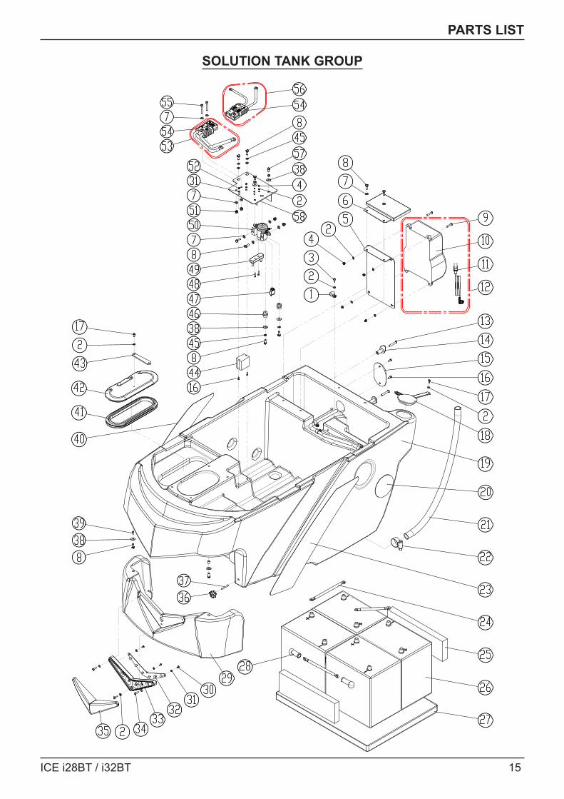
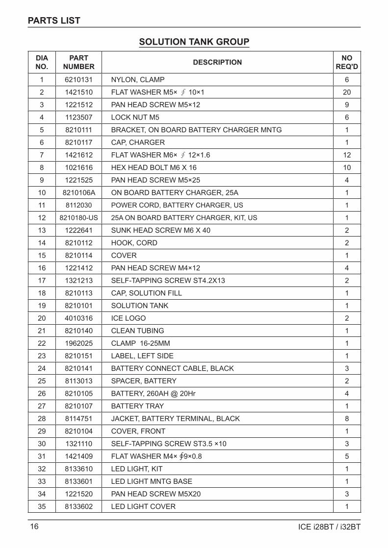
SOLUTION TANK GROUP
16 ICE i28BT / i32BT
PARTS LIST
SOLUTION TANK GROUPDIA NO.
PART NUMBER DESCRIPTION NO
REQ'D
1 6210131 NYLON, CLAMP 6
2 1421510 FLAT WASHER M5× ∮ 10×1 20
3 1221512 PAN HEAD SCREW M5×12 9
4 1123507 LOCK NUT M5 6
5 8210111 BRACKET, ON BOARD BATTERY CHARGER MNTG 1
6 8210117 CAP, CHARGER 1
7 1421612 FLAT WASHER M6× ∮ 12×1.6 12
8 1021616 HEX HEAD BOLT M6 X 16 10
9 1221525 PAN HEAD SCREW M5×25 4
10 8210106A ON BOARD BATTERY CHARGER, 25A 1
11 8112030 POWER CORD, BATTERY CHARGER, US 1
12 8210180-US 25A ON BOARD BATTERY CHARGER, KIT, US 1
13 1222641 SUNK HEAD SCREW M6 X 40 2
14 8210112 HOOK, CORD 2
15 8210114 COVER 1
16 1221412 PAN HEAD SCREW M4×12 4
17 1321213 SELF-TAPPING SCREW ST4.2X13 2
18 8210113 CAP, SOLUTION FILL 1
19 8210101 SOLUTION TANK 1
20 4010316 ICE LOGO 2
21 8210140 CLEAN TUBING 1
22 1962025 CLAMP 16-25MM 1
23 8210151 LABEL, LEFT SIDE 1
24 8210141 BATTERY CONNECT CABLE, BLACK 3
25 8113013 SPACER, BATTERY 2
26 8210105 BATTERY, 260AH @ 20Hr 4
27 8210107 BATTERY TRAY 1
28 8114751 JACKET, BATTERY TERMINAL, BLACK 8
29 8210104 COVER, FRONT 1
30 1321110 SELF-TAPPING SCREW ST3.5 ×10 3
31 1421409 FLAT WASHER M4× ∮9×0.8 5
32 8133610 LED LIGHT, KIT 1
33 8133601 LED LIGHT MNTG BASE 1
34 1221520 PAN HEAD SCREW M5X20 3
35 8133602 LED LIGHT COVER 1
ICE i28BT / i32BT 17
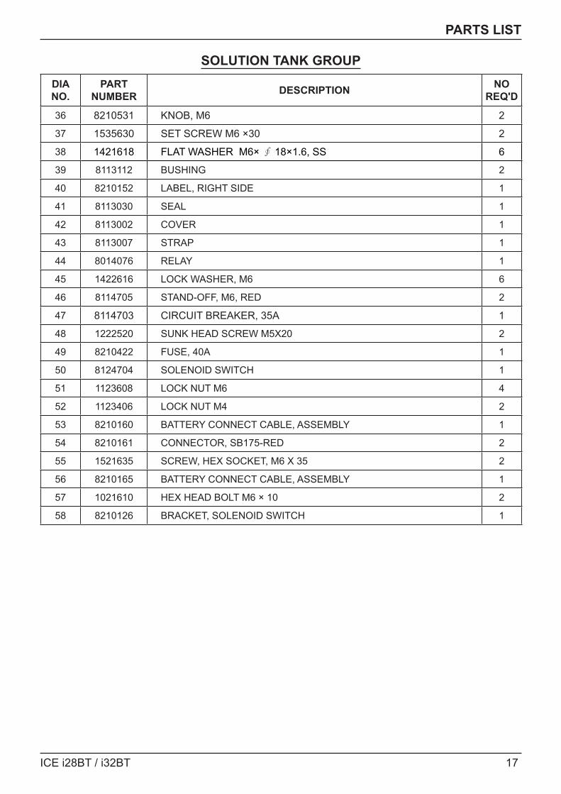
PARTS LIST
SOLUTION TANK GROUPDIA NO.
PART NUMBER DESCRIPTION NO
REQ'D
36 8210531 KNOB, M6 2
37 1535630 SET SCREW M6 ×30 2
38 1421618 FLAT WASHER M6× ∮ 18×1.6, SS 6
39 8113112 BUSHING 2
40 8210152 LABEL, RIGHT SIDE 1
41 8113030 SEAL 1
42 8113002 COVER 1
43 8113007 STRAP 1
44 8014076 RELAY 1
45 1422616 LOCK WASHER, M6 6
46 8114705 STAND-OFF, M6, RED 2
47 8114703 CIRCUIT BREAKER, 35A 1
48 1222520 SUNK HEAD SCREW M5X20 2
49 8210422 FUSE, 40A 1
50 8124704 SOLENOID SWITCH 1
51 1123608 LOCK NUT M6 4
52 1123406 LOCK NUT M4 2
53 8210160 BATTERY CONNECT CABLE, ASSEMBLY 1
54 8210161 CONNECTOR, SB175-RED 2
55 1521635 SCREW, HEX SOCKET, M6 X 35 2
56 8210165 BATTERY CONNECT CABLE, ASSEMBLY 1
57 1021610 HEX HEAD BOLT M6 × 10 2
58 8210126 BRACKET, SOLENOID SWITCH 1
18 ICE i28BT / i32BT
PARTS LIST
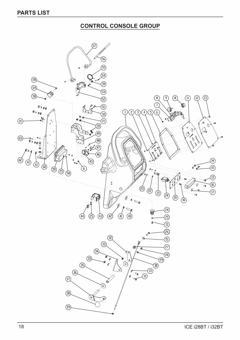
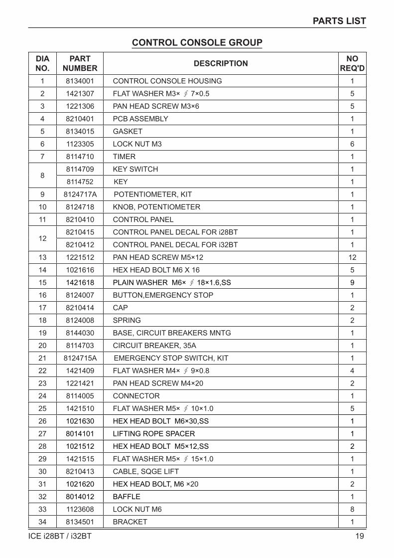
CONTROL CONSOLE GROUP
ICE i28BT / i32BT 19
PARTS LIST
CONTROL CONSOLE GROUPDIA NO.
PART NUMBER DESCRIPTION NO
REQ'D1 8134001 CONTROL CONSOLE HOUSING 1
2 1421307 FLAT WASHER M3× ∮ 7×0.5 5
3 1221306 PAN HEAD SCREW M3×6 5
4 8210401 PCB ASSEMBLY 1
5 8134015 GASKET 1
6 1123305 LOCK NUT M3 6
7 8114710 TIMER 1
88114709 KEY SWITCH 1
8114752 KEY 1
9 8124717A POTENTIOMETER, KIT 1
10 8124718 KNOB, POTENTIOMETER 1
11 8210410 CONTROL PANEL 1
128210415 CONTROL PANEL DECAL FOR i28BT 1
8210412 CONTROL PANEL DECAL FOR i32BT 1
13 1221512 PAN HEAD SCREW M5×12 12
14 1021616 HEX HEAD BOLT M6 X 16 5
15 1421618 PLAIN WASHER M6× ∮ 18×1.6,SS 9
16 8124007 BUTTON,EMERGENCY STOP 1
17 8210414 CAP 2
18 8124008 SPRING 2
19 8144030 BASE, CIRCUIT BREAKERS MNTG 1
20 8114703 CIRCUIT BREAKER, 35A 1
21 8124715A EMERGENCY STOP SWITCH, KIT 1
22 1421409 FLAT WASHER M4× ∮ 9×0.8 4
23 1221421 PAN HEAD SCREW M4×20 2
24 8114005 CONNECTOR 1
25 1421510 FLAT WASHER M5× ∮ 10×1.0 5
26 1021630 HEX HEAD BOLT M6×30,SS 1
27 8014101 LIFTING ROPE SPACER 1
28 1021512 HEX HEAD BOLT M5×12,SS 2
29 1421515 FLAT WASHER M5× ∮ 15×1.0 1
30 8210413 CABLE, SQGE LIFT 1
31 1021620 HEX HEAD BOLT, M6 ×20 2
32 8014012 BAFFLE 1
33 1123608 LOCK NUT M6 8
34 8134501 BRACKET 1
20 ICE i28BT / i32BT
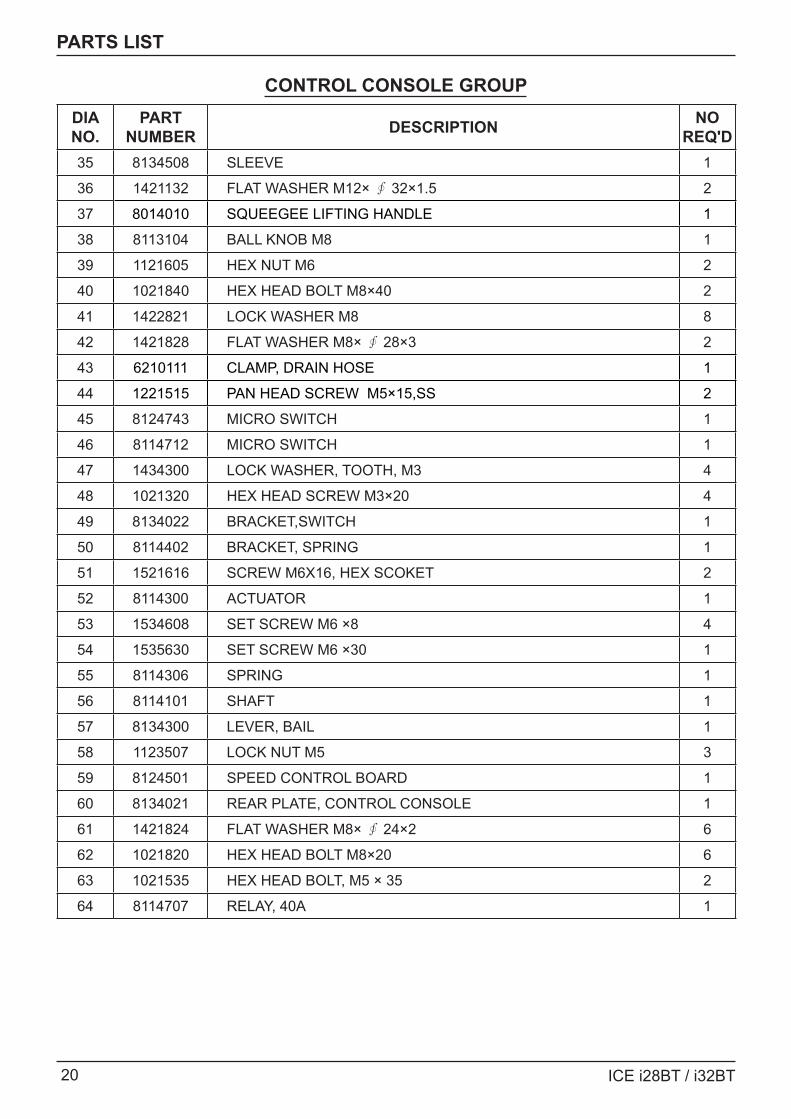
PARTS LIST
CONTROL CONSOLE GROUPDIA NO.
PART NUMBER DESCRIPTION NO
REQ'D35 8134508 SLEEVE 1
36 1421132 FLAT WASHER M12× ∮ 32×1.5 2
37 8014010 SQUEEGEE LIFTING HANDLE 1
38 8113104 BALL KNOB M8 1
39 1121605 HEX NUT M6 2
40 1021840 HEX HEAD BOLT M8×40 2
41 1422821 LOCK WASHER M8 8
42 1421828 FLAT WASHER M8× ∮ 28×3 2
43 6210111 CLAMP, DRAIN HOSE 1
44 1221515 PAN HEAD SCREW M5×15,SS 2
45 8124743 MICRO SWITCH 1
46 8114712 MICRO SWITCH 1
47 1434300 LOCK WASHER, TOOTH, M3 4
48 1021320 HEX HEAD SCREW M3×20 4
49 8134022 BRACKET,SWITCH 1
50 8114402 BRACKET, SPRING 1
51 1521616 SCREW M6X16, HEX SCOKET 2
52 8114300 ACTUATOR 1
53 1534608 SET SCREW M6 ×8 4
54 1535630 SET SCREW M6 ×30 1
55 8114306 SPRING 1
56 8114101 SHAFT 1
57 8134300 LEVER, BAIL 1
58 1123507 LOCK NUT M5 3
59 8124501 SPEED CONTROL BOARD 1
60 8134021 REAR PLATE, CONTROL CONSOLE 1
61 1421824 FLAT WASHER M8× ∮ 24×2 6
62 1021820 HEX HEAD BOLT M8×20 6
63 1021535 HEX HEAD BOLT, M5 × 35 2
64 8114707 RELAY, 40A 1
ICE i28BT / i32BT 21
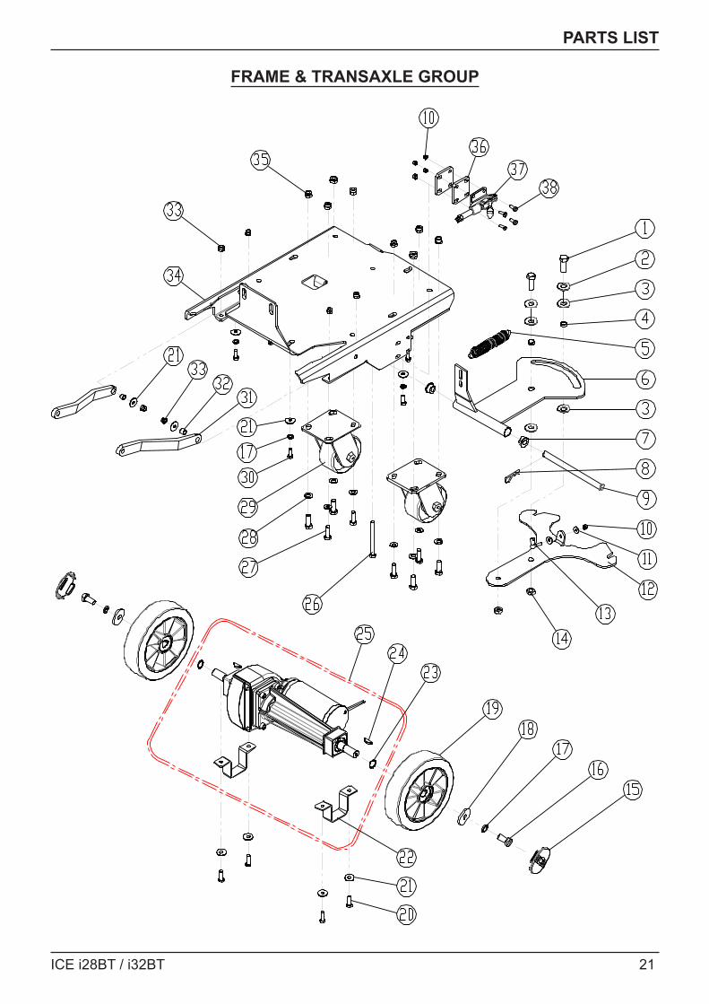
PARTS LIST
FRAME & TRANSAXLE GROUP
22 ICE i28BT / i32BT
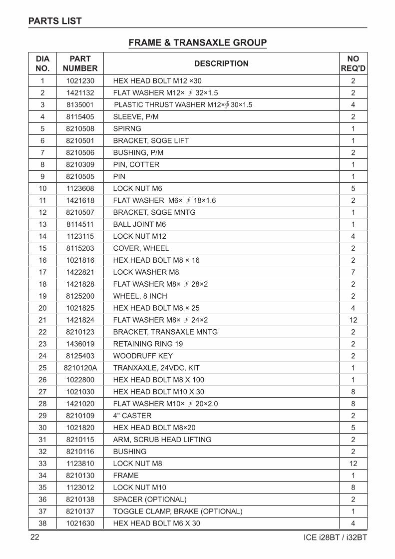
PARTS LIST
FRAME & TRANSAXLE GROUPDIA NO.
PART NUMBER DESCRIPTION NO
REQ'D1 1021230 HEX HEAD BOLT M12 ×30 22 1421132 FLAT WASHER M12× ∮ 32×1.5 23 8135001 PLASTIC THRUST WASHER M12×∮ 30×1.5 44 8115405 SLEEVE, P/M 25 8210508 SPIRNG 16 8210501 BRACKET, SQGE LIFT 17 8210506 BUSHING, P/M 28 8210309 PIN, COTTER 19 8210505 PIN 1
10 1123608 LOCK NUT M6 511 1421618 FLAT WASHER M6× ∮ 18×1.6 212 8210507 BRACKET, SQGE MNTG 113 8114511 BALL JOINT M6 114 1123115 LOCK NUT M12 415 8115203 COVER, WHEEL 216 1021816 HEX HEAD BOLT M8 × 16 217 1422821 LOCK WASHER M8 718 1421828 FLAT WASHER M8× ∮ 28×2 219 8125200 WHEEL, 8 INCH 220 1021825 HEX HEAD BOLT M8 × 25 421 1421824 FLAT WASHER M8× ∮ 24×2 1222 8210123 BRACKET, TRANSAXLE MNTG 223 1436019 RETAINING RING 19 224 8125403 WOODRUFF KEY 225 8210120A TRANXAXLE, 24VDC, KIT 126 1022800 HEX HEAD BOLT M8 X 100 127 1021030 HEX HEAD BOLT M10 X 30 828 1421020 FLAT WASHER M10× ∮ 20×2.0 829 8210109 4" CASTER 230 1021820 HEX HEAD BOLT M8×20 531 8210115 ARM, SCRUB HEAD LIFTING 232 8210116 BUSHING 233 1123810 LOCK NUT M8 1234 8210130 FRAME 135 1123012 LOCK NUT M10 836 8210138 SPACER (OPTIONAL) 237 8210137 TOGGLE CLAMP, BRAKE (OPTIONAL) 138 1021630 HEX HEAD BOLT M6 X 30 4
ICE i28BT / i32BT 23
PARTS LIST
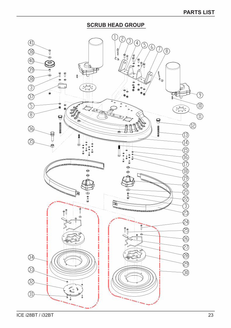
SCRUB HEAD GROUP
24 ICE i28BT / i32BT
PARTS LIST
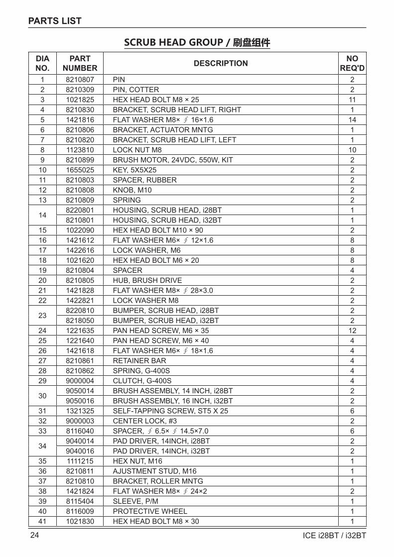
SCRUB HEAD GROUP / 刷盘组件
DIA NO.
PART NUMBER DESCRIPTION NO
REQ'D1 8210807 PIN 22 8210309 PIN, COTTER 23 1021825 HEX HEAD BOLT M8 × 25 114 8210830 BRACKET, SCRUB HEAD LIFT, RIGHT 15 1421816 FLAT WASHER M8× ∮ 16×1.6 146 8210806 BRACKET, ACTUATOR MNTG 17 8210820 BRACKET, SCRUB HEAD LIFT, LEFT 18 1123810 LOCK NUT M8 109 8210899 BRUSH MOTOR, 24VDC, 550W, KIT 2
10 1655025 KEY, 5X5X25 211 8210803 SPACER, RUBBER 212 8210808 KNOB, M10 213 8210809 SPRING 2
148220801 HOUSING, SCRUB HEAD, i28BT 18210801 HOUSING, SCRUB HEAD, i32BT 1
15 1022090 HEX HEAD BOLT M10 × 90 216 1421612 FLAT WASHER M6× ∮ 12×1.6 817 1422616 LOCK WASHER, M6 818 1021620 HEX HEAD BOLT M6 × 20 819 8210804 SPACER 420 8210805 HUB, BRUSH DRIVE 221 1421828 FLAT WASHER M8× ∮ 28×3.0 222 1422821 LOCK WASHER M8 2
238220810 BUMPER, SCRUB HEAD, i28BT 28218050 BUMPER, SCRUB HEAD, i32BT 2
24 1221635 PAN HEAD SCREW, M6 × 35 1225 1221640 PAN HEAD SCREW, M6 × 40 426 1421618 FLAT WASHER M6× ∮ 18×1.6 427 8210861 RETAINER BAR 428 8210862 SPRING, G-400S 429 9000004 CLUTCH, G-400S 4
309050014 BRUSH ASSEMBLY, 14 INCH, i28BT 29050016 BRUSH ASSEMBLY, 16 INCH, i32BT 2
31 1321325 SELF-TAPPING SCREW, ST5 X 25 632 9000003 CENTER LOCK, #3 233 8116040 SPACER, ∮ 6.5× ∮ 14.5×7.0 6
349040014 PAD DRIVER, 14INCH, i28BT 29040016 PAD DRIVER, 14INCH, i32BT 2
35 1111215 HEX NUT, M16 136 8210811 AJUSTMENT STUD, M16 137 8210810 BRACKET, ROLLER MNTG 138 1421824 FLAT WASHER M8× ∮ 24×2 239 8115404 SLEEVE, P/M 140 8116009 PROTECTIVE WHEEL 141 1021830 HEX HEAD BOLT M8 × 30 1
ICE i28BT / i32BT 25
PARTS LIST
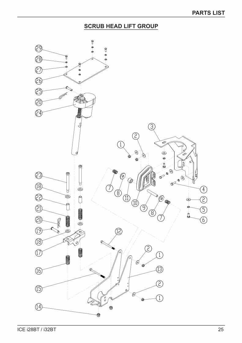
SCRUB HEAD LIFT GROUP
26 ICE i28BT / i32BT
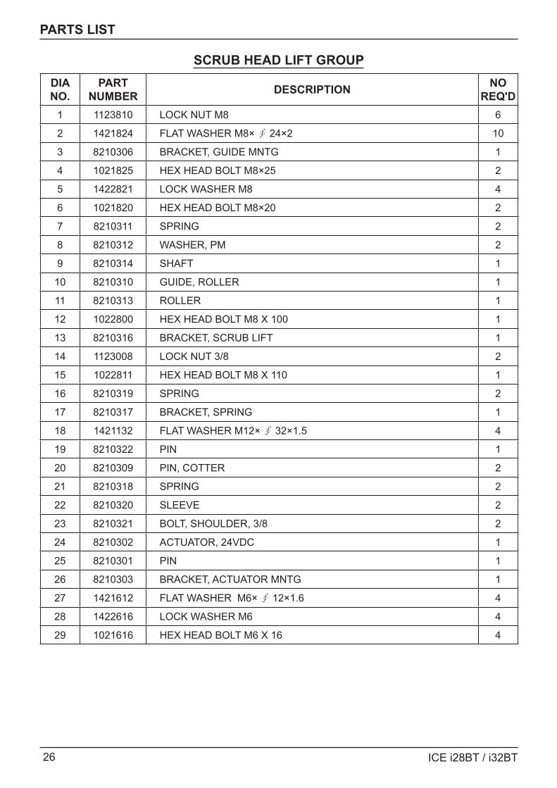
PARTS LIST
SCRUB HEAD LIFT GROUPDIA NO.
PART NUMBER DESCRIPTION NO
REQ'D1 1123810 LOCK NUT M8 6
2 1421824 FLAT WASHER M8× ∮ 24×2 10
3 8210306 BRACKET, GUIDE MNTG 1
4 1021825 HEX HEAD BOLT M8×25 2
5 1422821 LOCK WASHER M8 4
6 1021820 HEX HEAD BOLT M8×20 2
7 8210311 SPRING 2
8 8210312 WASHER, PM 2
9 8210314 SHAFT 1
10 8210310 GUIDE, ROLLER 1
11 8210313 ROLLER 1
12 1022800 HEX HEAD BOLT M8 X 100 1
13 8210316 BRACKET, SCRUB LIFT 1
14 1123008 LOCK NUT 3/8 2
15 1022811 HEX HEAD BOLT M8 X 110 1
16 8210319 SPRING 2
17 8210317 BRACKET, SPRING 1
18 1421132 FLAT WASHER M12× ∮ 32×1.5 4
19 8210322 PIN 1
20 8210309 PIN, COTTER 2
21 8210318 SPRING 2
22 8210320 SLEEVE 2
23 8210321 BOLT, SHOULDER, 3/8 2
24 8210302 ACTUATOR, 24VDC 1
25 8210301 PIN 1
26 8210303 BRACKET, ACTUATOR MNTG 1
27 1421612 FLAT WASHER M6× ∮ 12×1.6 4
28 1422616 LOCK WASHER M6 4
29 1021616 HEX HEAD BOLT M6 X 16 4
ICE i28BT / i32BT 27
PARTS LIST
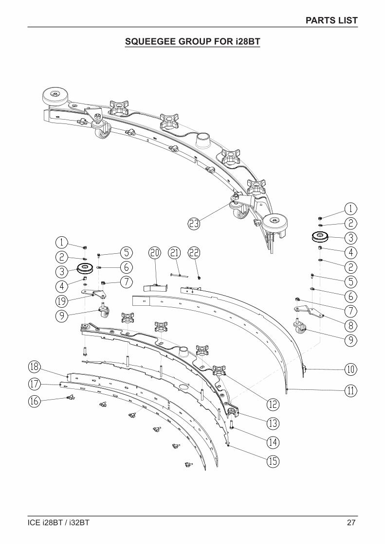
SQUEEGEE GROUP FOR i28BT
28 ICE i28BT / i32BT
PARTS LIST
SQUEEGEE GROUP FOR i28BTDIA NO.
PART NUMBER DESCRIPTION NO
REQ'D1 1123810 LOCK NUT M8 2
2 1421824 FLAT WASHER M8× ∮ 24×2.0 4
3 8116009 PROTECTIVE WHEEL 2
4 8115404 BEARING, JOURNAL 2
5 1021616 HEX BOLT M6×16 2
6 1421612 FLAT WASHER M6× ∮ 12×1.6 2
7 1121008 HEX NUT M10 2
8 8118300 RIGHT BRACKET 1
9 8118400 CASTER, 2 INCH 2
10 8310514 CLAMP ASSEMBLY 1
118310531 SQUEEGEE BLADE, REAR, LINATEX 1
8310541 SQUEEGEE BLADE, REAR, PU (OPTIONAL) 1
12 8210518 KNOB, M8 4
13 8310511 SQUEEGEE HOSING 1
14 1021835 BOLT, HEX HEAD, M8×35 2
15 8310512 RETAINER, SQUEEGEE 1
16 8210530 KNOB, M6 6
17 8310513 FRONT CLAMP 1
188310532 SQUEEGEE BLADE, FRONT, LINATEX 1
8310542 SQUEEGEE BLADE, FRONT, PU (OPTIONAL) 1
19 8118200 LEFT BRACKET 1
20 8210525 SHORT CLAMP ASSEMBLY 1
21 1221575 SCREW, PAN HEAD, M5×75 1
22 1123507 LOCK NUT, M5 1
23 8310510 SQUEEGEE ASSEMBLY FOR i28BT , 1030mm 1
ICE i28BT / i32BT 29
PARTS LIST
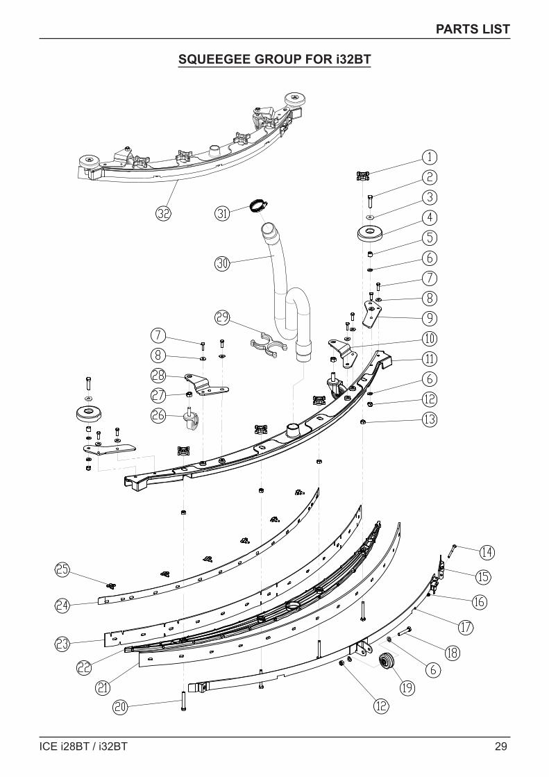
SQUEEGEE GROUP FOR i32BT
30 ICE i28BT / i32BT
PARTS LIST
SQUEEGEE GROUP FOR i32BTDIA NO.
PART NUMBER DESCRIPTION NO
REQ'D1 8118003 STAR KNOB M8 4
2 1021835 HEX HEAD BOLT M8×35 2
3 1421824 FLAT WASHER M8× ∮ 24×2.0 2
4 8116009 PROTECTIVE WHEEL 2
5 8115404 BEARING, JOURNAL 2
6 1421816 FLAT WASHER M8× ∮ 16×1.6 6
7 1021616 HEX HEAD BOLT M6×16 8
8 1421618 FLAT WASHER M6× ∮ 18×1.6 8
9 8210515 BRACKET, ROLLER MNTG 2
10 8118300 RIGHT BRACKET 1
11 8210511 SQUEEGEE HOUSING 1
12 1123810 LOCK NUT M8 2
13 1121807 HEX NUT M8 4
14 1221575 PAN HEAD SCREW M5×75 1
15 8210525 SHORT CLAMP ASSEBLY 1
16 1123507 LOCK NUT M5 1
17 8210520 CLAMP ASSEMBLY, SQUEEGEE 1
18 1022845 HEX HEAD BOLT M8×45 1
19 8210527 WHEEL, 2 INCH 1
20 1021860 HEX HEAD BOLT M8×60 4
218210514 SQUEEGEE BLADE, REAR, LINATEX 1
8210517 SQUEEGEE BLADE, REAR, PU (OPTIONAL) 1
22 8210512 RETAINER,SQUEEGEE 1
238210513 SQUEEGEE BLADE, FRONT, LINATEX 1
8210516 SQUEEGEE BLADE, FRONT, PU (OPTIONAL) 1
24 8210519 CLAMP, FRONT BLADE 1
25 8210530 KNOB, M6 6
26 8118400 CASTER, 2 INCH 2
27 1121008 HEX NUT M10 2
28 8118200 LEFT BRACKET 1
29 8118109 HOLDER VACUUM HOSE 1
30 8118006 VACUUM HOSE 1
31 1962050 CLAMP 1
32 8210510 SQUEEGEE ASSEMBLY FOR i32BT, 1185mm 1
ICE i28BT / i32BT 31
PARTS LIST
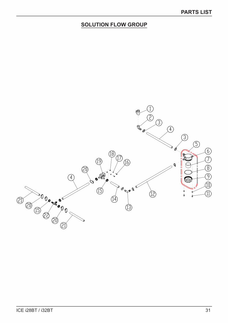
SOLUTION FLOW GROUP
32 ICE i28BT / i32BT
PARTS LIST
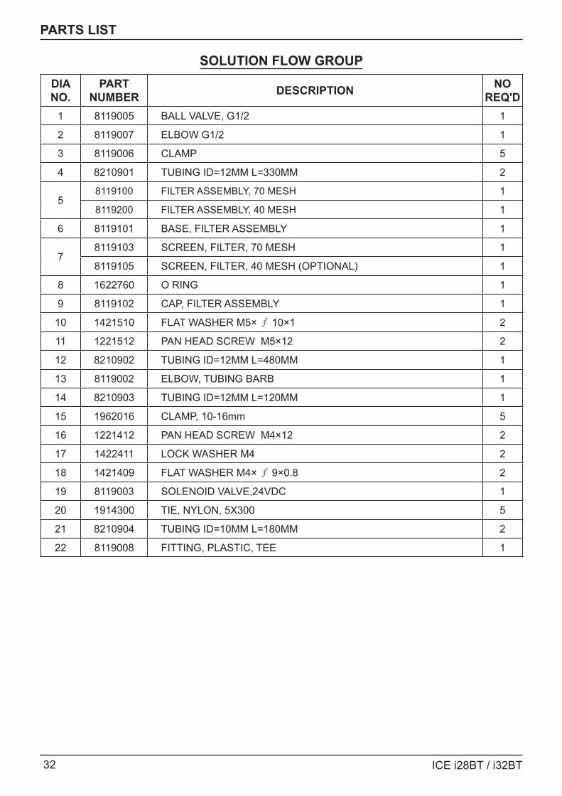
SOLUTION FLOW GROUPDIA NO.
PART NUMBER DESCRIPTION NO
REQ'D1 8119005 BALL VALVE, G1/2 1
2 8119007 ELBOW G1/2 1
3 8119006 CLAMP 5
4 8210901 TUBING ID=12MM L=330MM 2
58119100 FILTER ASSEMBLY, 70 MESH 1
8119200 FILTER ASSEMBLY, 40 MESH 1
6 8119101 BASE, FILTER ASSEMBLY 1
78119103 SCREEN, FILTER, 70 MESH 1
8119105 SCREEN, FILTER, 40 MESH (OPTIONAL) 1
8 1622760 O RING 1
9 8119102 CAP, FILTER ASSEMBLY 1
10 1421510 FLAT WASHER M5× ∮ 10×1 2
11 1221512 PAN HEAD SCREW M5×12 2
12 8210902 TUBING ID=12MM L=480MM 1
13 8119002 ELBOW, TUBING BARB 1
14 8210903 TUBING ID=12MM L=120MM 1
15 1962016 CLAMP, 10-16mm 5
16 1221412 PAN HEAD SCREW M4×12 2
17 1422411 LOCK WASHER M4 2
18 1421409 FLAT WASHER M4× ∮ 9×0.8 2
19 8119003 SOLENOID VALVE,24VDC 1
20 1914300 TIE, NYLON, 5X300 5
21 8210904 TUBING ID=10MM L=180MM 2
22 8119008 FITTING, PLASTIC, TEE 1
ICE i28BT / i32BT 33
PARTS LIST
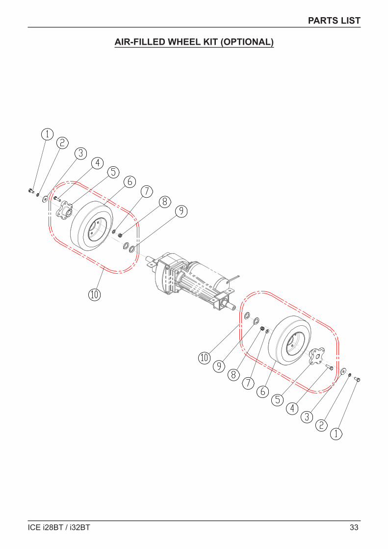
AIR-FILLED WHEEL KIT (OPTIONAL)
34 ICE i28BT / i32BT
PARTS LIST
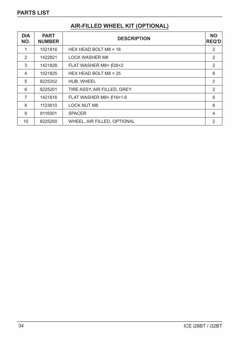
AIR-FILLED WHEEL KIT (OPTIONAL)DIA NO.
PART NUMBER DESCRIPTION NO
REQ'D1 1021816 HEX HEAD BOLT M8 × 16 2
2 1422821 LOCK WASHER M8 2
3 1421828 FLAT WASHER M8× ∮28×2 2
4 1021825 HEX HEAD BOLT M8 × 25 8
5 8225202 HUB, WHEEL 2
6 8225201 TIRE ASSY, AIR FILLED, GREY 2
7 1421816 FLAT WASHER M8× ∮16×1.6 8
8 1123810 LOCK NUT M8 8
9 8116001 SPACER 4
10 8225200 WHEEL, AIR FILLED, OPTIONAL 2
ICE i28BT / i32BT 35
WEAR AND TEAR PARTS
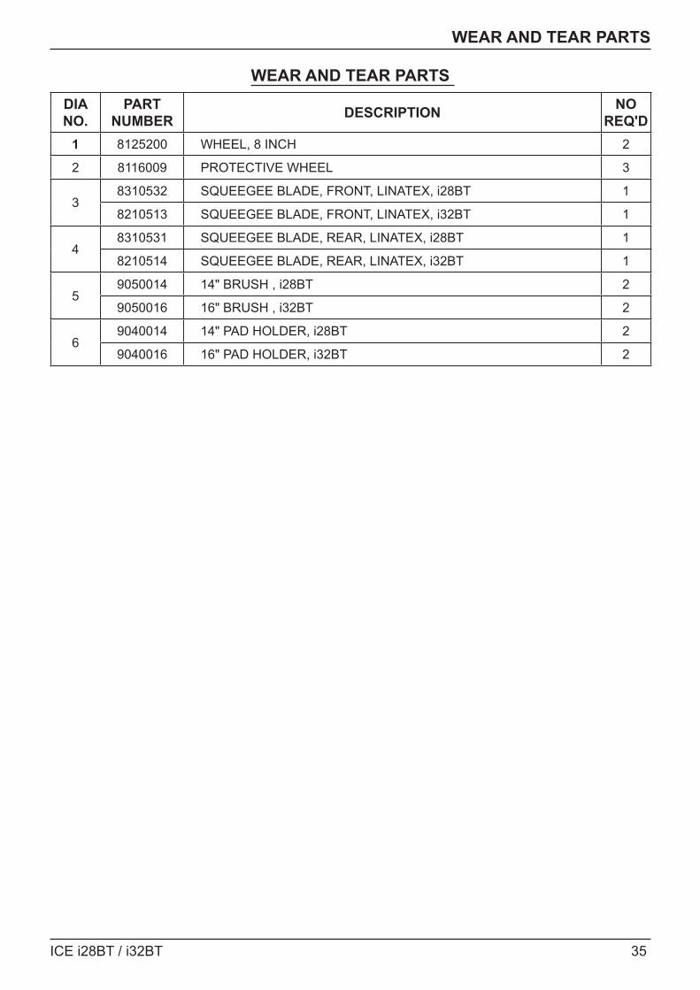
WEAR AND TEAR PARTS DIA NO.
PART NUMBER DESCRIPTION NO
REQ'D1 8125200 WHEEL, 8 INCH 2
2 8116009 PROTECTIVE WHEEL 3
38310532 SQUEEGEE BLADE, FRONT, LINATEX, i28BT 1
8210513 SQUEEGEE BLADE, FRONT, LINATEX, i32BT 1
48310531 SQUEEGEE BLADE, REAR, LINATEX, i28BT 1
8210514 SQUEEGEE BLADE, REAR, LINATEX, i32BT 1
59050014 14" BRUSH , i28BT 2
9050016 16" BRUSH , i32BT 2
69040014 14" PAD HOLDER, i28BT 2
9040016 16" PAD HOLDER, i32BT 2
36 ICE i28BT / i32BT
WIRING DIAGRAM
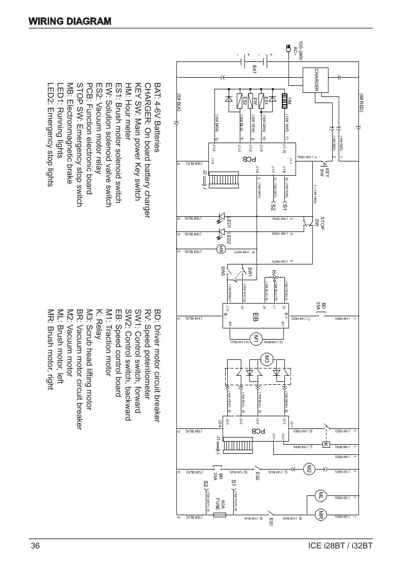
BD
: Driver m
otor circuit breakerR
V: Speed potentiom
eterS
W1: C
ontrol switch, forw
ardS
W2: C
ontrol switch, backw
ardE
B: S
peed control boardM
1: Traction motor
K: R
elayM
3: Scrub head lifting m
otorB
R: Vacuum
motor circuit breaker
M2: Vacuum
motor
ML: B
rush motor, left
MR
: Brush m
otor, right
BAT: 4-6V
Batteries
CH
AR
GE
R: O
n board battery charger K
EY S
W: M
ain power K
ey switch
HM
: Hour m
eterE
S1: B
rush motor solenoid sw
itchE
W: S
olution solenoid valve switch
ES
2: Vacuum m
otor relayP
CB
: Function electronic boardS
TOP S
W: E
mergency stop sw
itchM
B: E
lectronmagnetic brake
LED
1: Running lights
LED
2: Em
ergency stop lights