Embed Size (px)
DESCRIPTION
Higher Technological Institute Electrical Department. Automatic Transfer Switch using microcontroller. Advisor/ Dr Hussein Taraf By/ Heba Mohamed Mohamed Farouk Abdallah Mohamed Mohamed Ali. Graduation Project Presentation July 30, 2013. Starting Quotation…. - PowerPoint PPT Presentation
Citation preview
Automatic Transfer Switch using microcontroller
Advisor/Dr Hussein TarafBy/ Heba Mohamed Mohamed Farouk
Abdallah Mohamed Mohamed Ali
Graduation Project PresentationJuly 30, 2013
Higher Technological InstituteElectrical Department
Starting Quotation…Power failure or outage in general does not promote development in the public and private sector. Investors do not feel secure to operate in a country with constant or frequent power failure.
Most industrial and commercial processes are dependent on electrical power.
The need for continuous power supply and its reliability has increased rapidly over the years, especially in all those areas where uninterrupted power supply is a must. Modern systems are power dependent. Their complexity has increased as continuous information and communications are needed to control automated process, be it in industries, commercial complexes,
hospitals, hotels and airports.
The need for independent standby power system has therefore increased . So it is necessary to use either ups or the transfer switches as alternative power source.
AND NOWWhat is the difference between ups and transfer switches?
So ,
We will notice that The difference between them lies in the difference in the dark time
Where dark time can be defined as the time where there is no current load.So the following graph shows this difference :
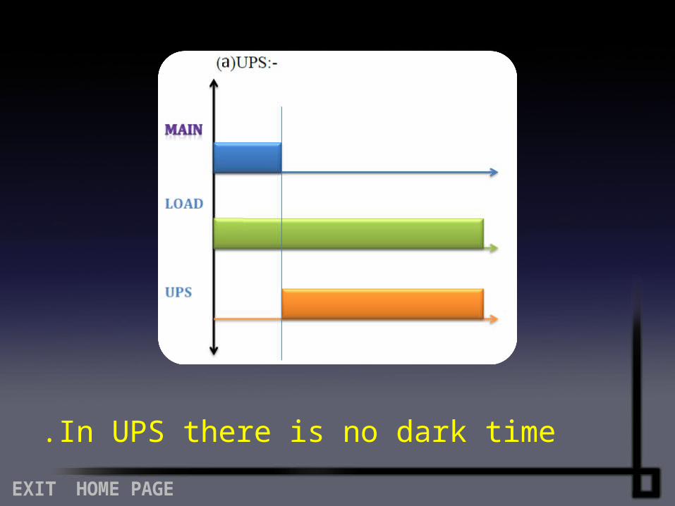
In UPS there is no dark time.
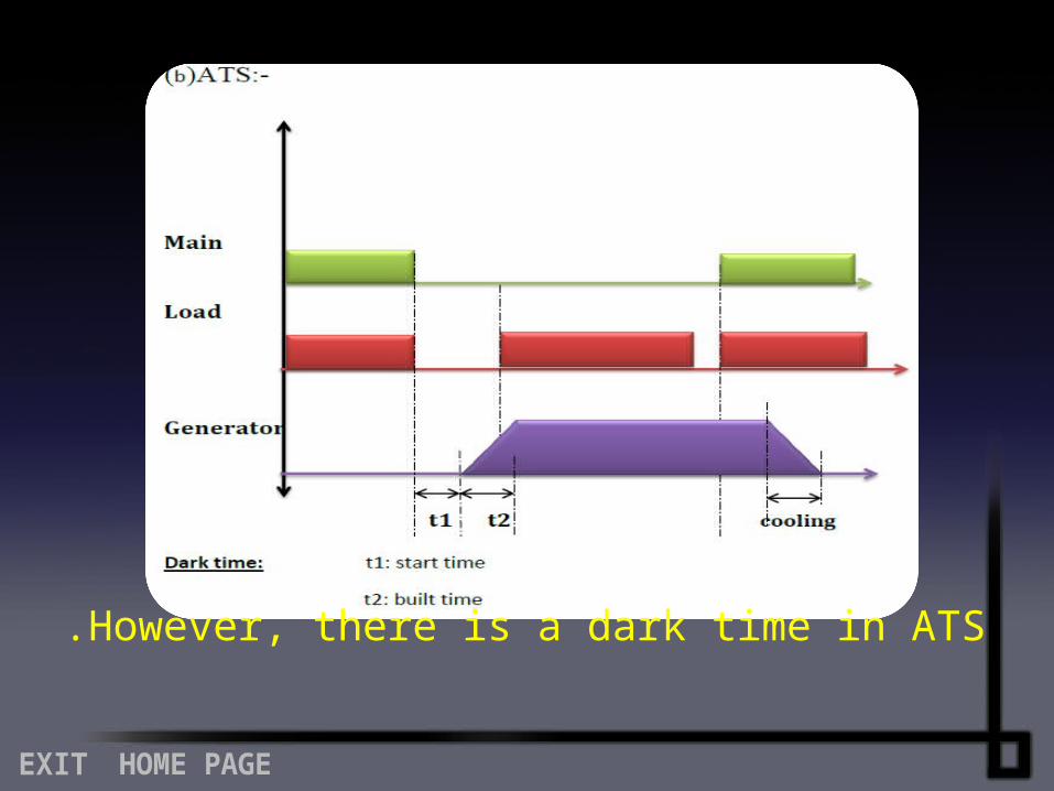
However, there is a dark time in ATS.
Transfer switches:
Transfer Switches allow switching from a primary power source to a secondary power source and are employed in some electrical power distribution systems; most often transfer switches can be seen where emergency power generators are used to back up from the utility source. The transfer switching allows safely switching from utility power to emergency generator power while maintaining
isolation of each source from the other .
2013
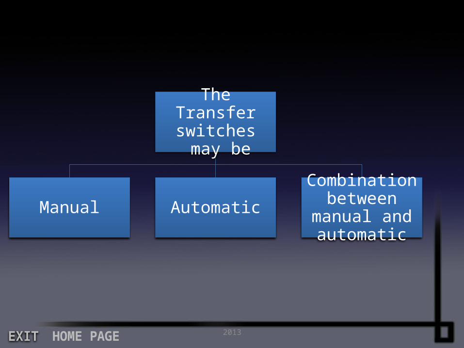
The Transfer switches may be
Manual AutomaticCombination
between manual and automatic
2013
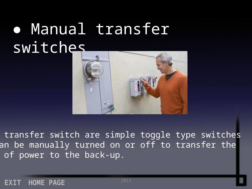
● Manual transfer switches
Manual transfer switch are simple toggle type switchesthat can be manually turned on or off to transfer thesource of power to the back-up.
2013
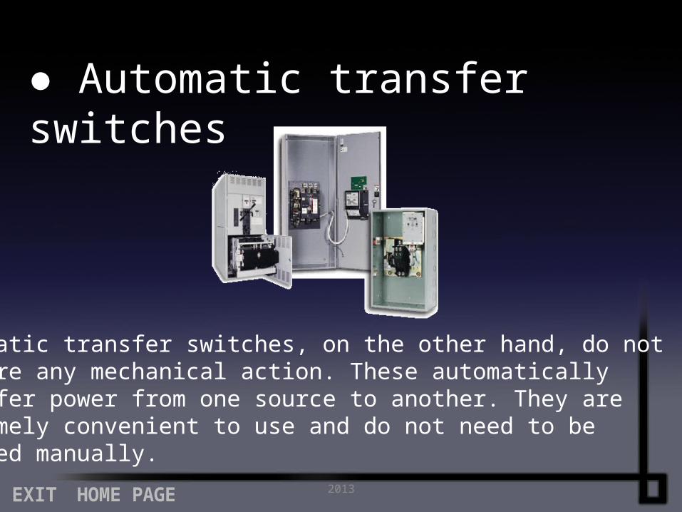
● Automatic transfer switches
Automatic transfer switches, on the other hand, do notrequire any mechanical action. These automaticallytransfer power from one source to another. They are extremely convenient to use and do not need to betoggled manually.

So, let us illustrate our project theme……
The purpose of this project is to design and construct an automatic changeover switch that provides a solution to the erratic power supply problem we are facing today. The automatic changeover switch is a unique switching system that can be used to effect the change from one power supply to another as well as to ensuring consistency in the supply to a particular network or load. The another function of changeover switch is to interface between two different electrical
power sources (the mains supply and the generator) .
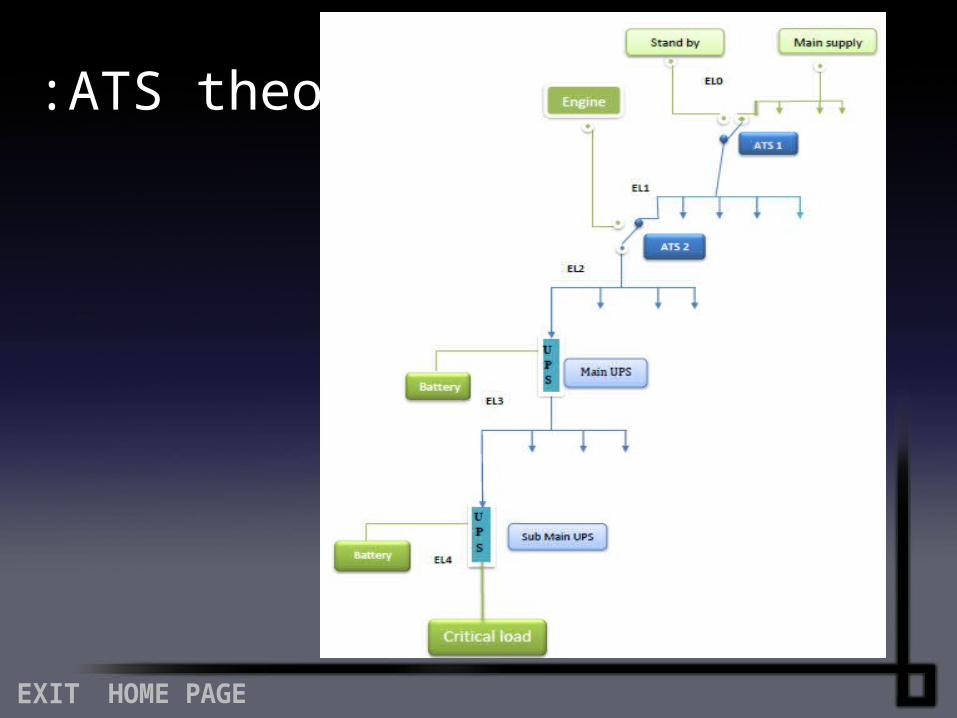
ATS theory:
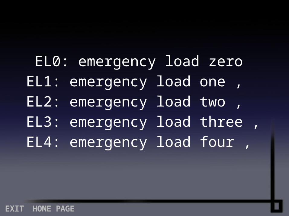
EL0: emergency load zero , EL1: emergency load one , EL2: emergency load two
, EL3: emergency load three , EL4: emergency load four
what is the sequence of operation in ATS project???
So,So,
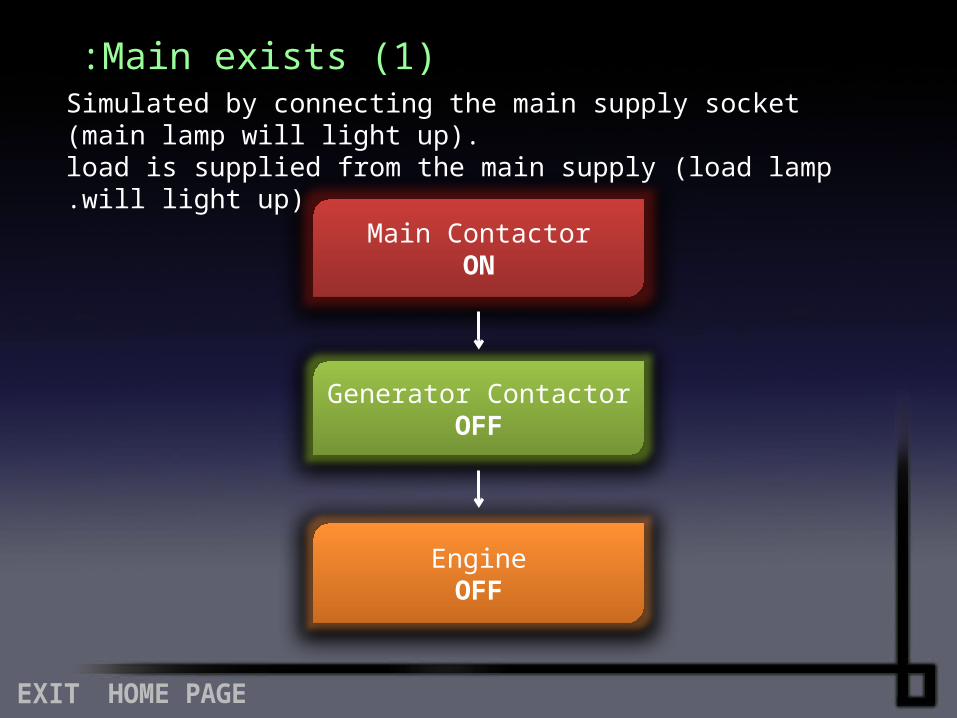
(1 )Main exists:
Main ContactorON
Generator ContactorOFF
EngineOFF
Simulated by connecting the main supply socket (main lamp will light up).load is supplied from the main supply (load lamp will light up).
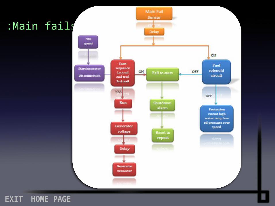
(2 )Main fails:
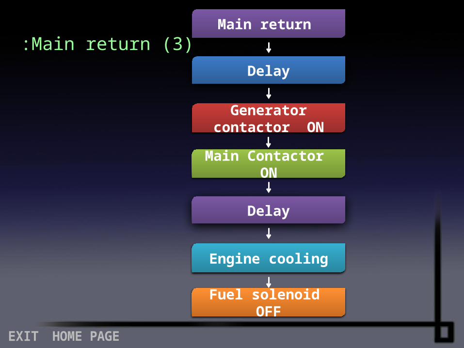
Main return
Delay
Generator contactor ON
Main Contactor ON
Delay
Engine cooling
Fuel solenoid OFF
(3 )Main return:
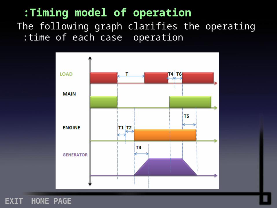
Timing model of operation :The following graph clarifies the operating time of each case
operation :
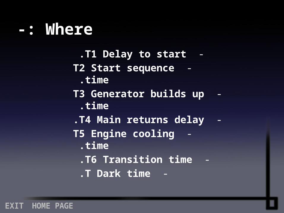
Where-: -T1 Delay to start .
-T2 Start sequence time . -T3 Generator builds up time .
-T4 Main returns delay . -T5 Engine cooling time .
-T6 Transition time . -T Dark time .
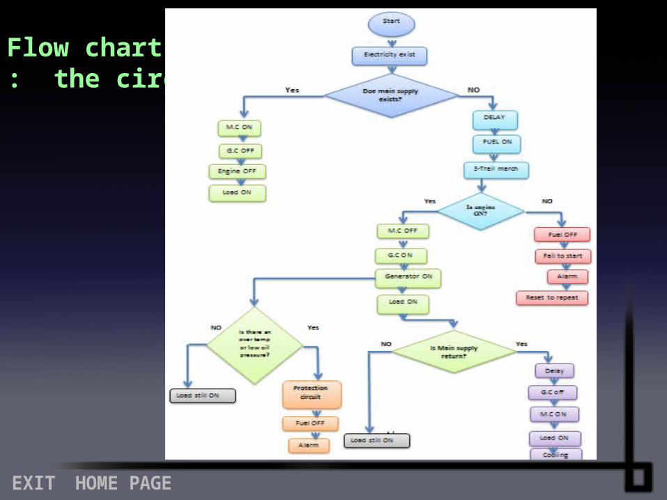
Flow chart of the circuit:
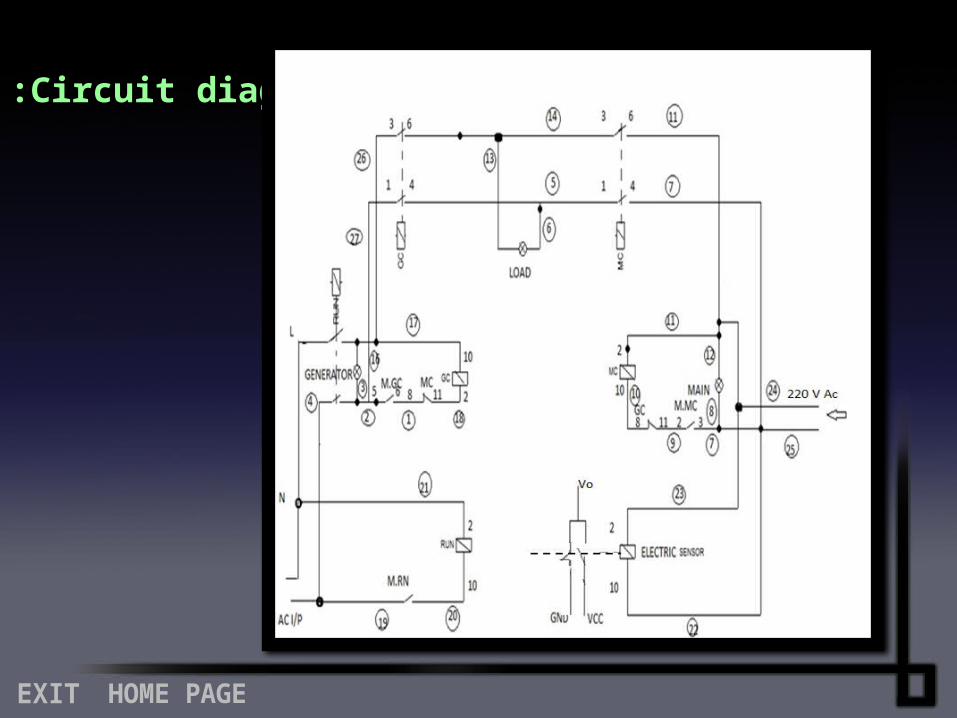
Circuit diagram:
And now, let us talk about diesel generator....?
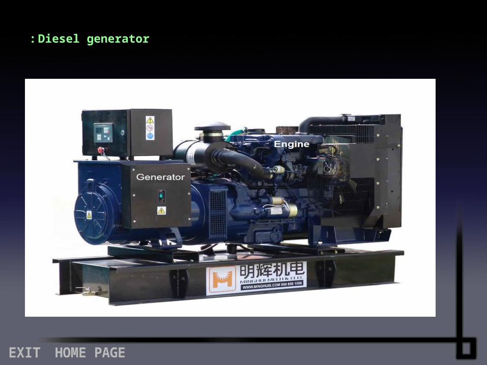
Diesel generator :
A diesel generator is the combination of a diesel engine with an electrical generator (often an alternator) to generate electrical energy. Diesel generating sets are used in places without connection to the power grid, as emergency power-supply if the grid fails, as well as for more complex applications such as peak-lopping, grid support and export to the power grid. Sizing of diesel generators is critical to avoid low-load or a shortage of power and is complicated by modern electronics,
specifically non-linear loads.
Diesel generators are capable of providing power at various sites where power is required like civil work and construction sites as well as are also employed in various facilities as emergency power source for critical equipment like medical equipment in hospital, bank online system and
traffic signals etc .
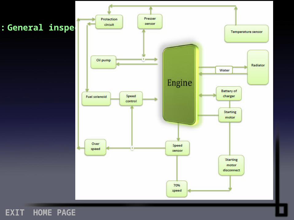
General inspection :
In our project we use the microcontroller for controlling the project we will show what is the
microcontroller briefly..……
Microcontroller :A microcontroller (sometimes abbreviated μC, uC or MCU) is a small computer on a single integrated circuit containing a processor core, memory, and programmable input/output peripherals.Program memory in the form of NOR flash or OTP ROM is also often included on chip, as well as a typically small amount of RAM. Microcontrollers are designed for embedded applications, in contrast to the microprocessors used in personal computers or other
general purpose applications.
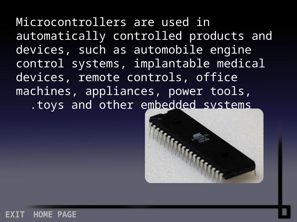
Microcontrollers are used in automatically controlled products and devices, such as automobile engine control systems, implantable medical devices, remote controls, office machines, appliances, power tools, toys
and other embedded systems .
And those are some of classic components which we use for our project.……
Miniature Circuit Breaker :
A circuit breaker is an automatically operated electrical switch designed to protect an electrical circuit from damage caused by overload or short circuit. Its basic function is to detect a fault condition and, by interrupting continuity, to immediately discontinue electrical flow. Unlike a fuse, which operates once and then must be replaced, a circuit breaker can be reset (either manually or automatically) to resume normal
operation .
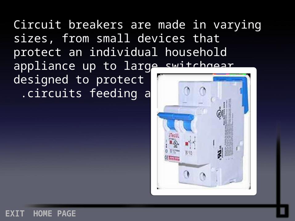
Circuit breakers are made in varying sizes, from small devices that protect an individual household appliance up to large switchgear designed to protect high voltage
circuits feeding an entire city .
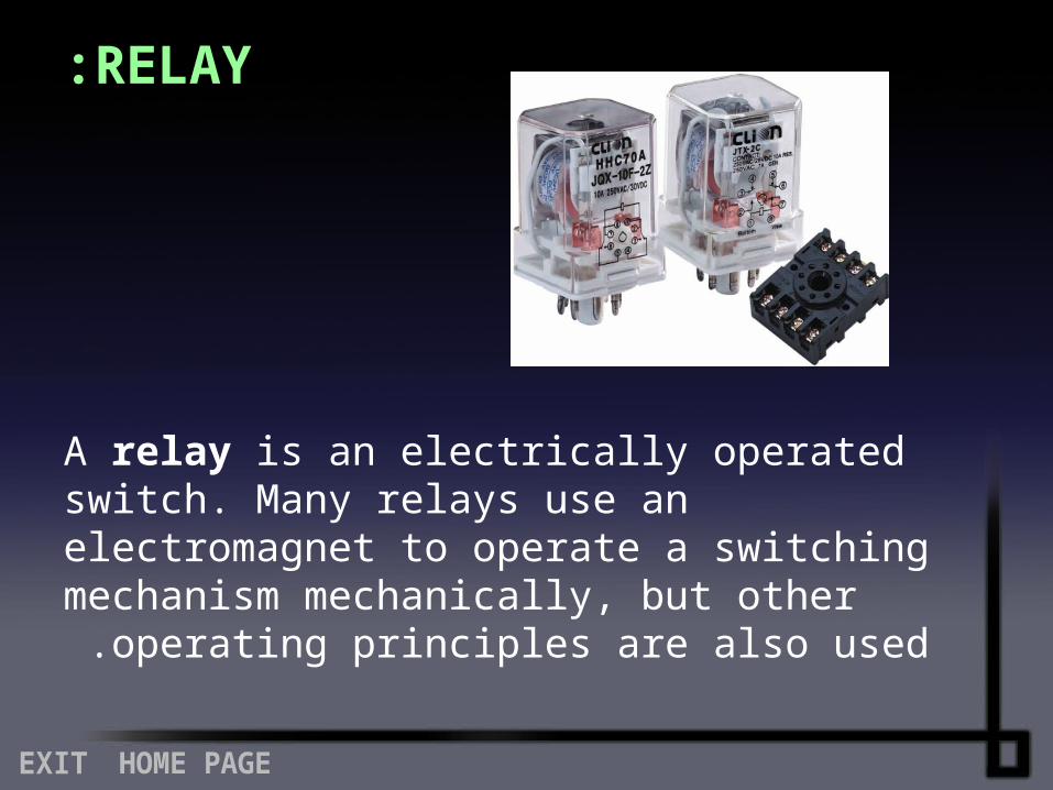
RELAY :
A relay is an electrically operated switch. Many relays use an electromagnet to operate a switching mechanism mechanically, but other operating
principles are also used .
Relays are used where it is necessary to control a circuit by a low-power signal (with complete electrical isolation between control and controlled circuits), or where several circuits must be controlled by one signal. The first relays were used in long distance telegraph circuits, repeating the signal coming in from one circuit and re-transmitting it to another. Relays were used extensively in telephone exchanges and early
computers to perform logical operations .
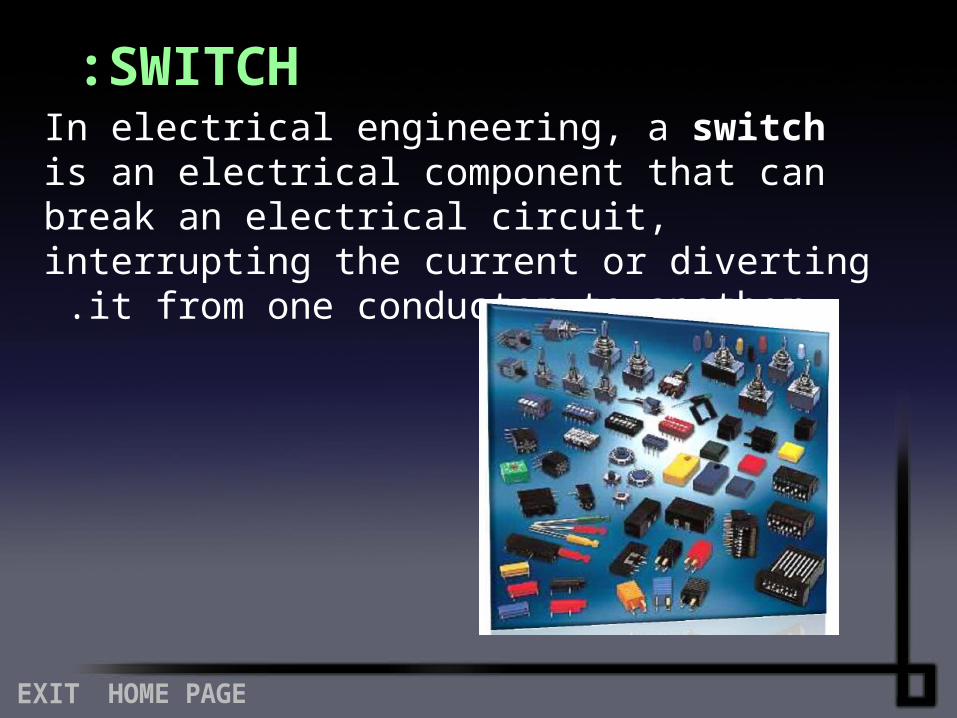
SWITCH :In electrical engineering, a switch is an electrical component that can break an electrical circuit, interrupting the current or diverting it from one
conductor to another .
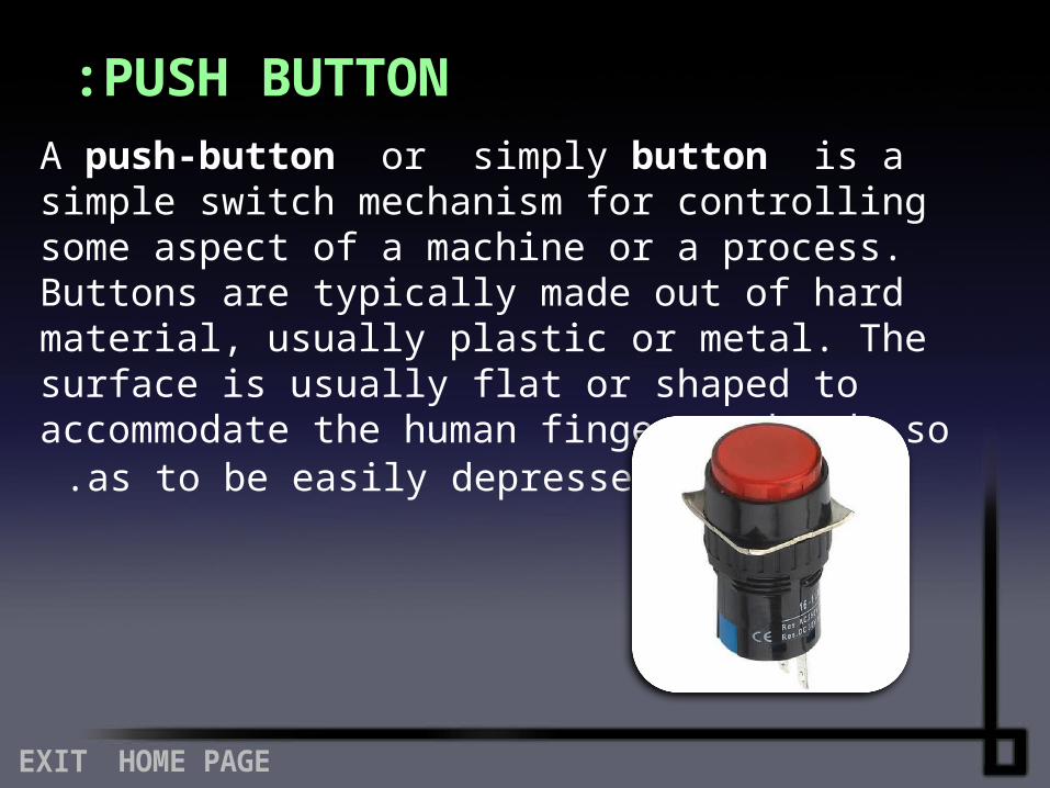
PUSH BUTTON :
A push-button or simply button is a simple switch mechanism for controlling some aspect of a machine or a process. Buttons are typically made out of hard material, usually plastic or metal. The surface is usually flat or shaped to accommodate the human finger or hand, so as to be easily
depressed or pushed.

uT h a n k Y o