Embed Size (px)
Citation preview
Mohammad Ali Jinnah University, Islamabad.
Automatic Washbasin Tap Controller Project Report
Author: Zaheer ul hauqe

Automatic Washbasin Tap Controller | Zaheer ul hauqe
Page 1 of 11 Mohammad Ali Jinnah University, Islamabad.
Abstract
This is a student report for the Lab Project assigned for Basic Electronics lab, named Automatic
Washbasin Tap Controller. It encloses the working and theory of IC 555 timer, Solenoid Valve,
IRs and IR receivers. The findings, experience and knowledge that we have learned during the
course of fabrication and implementing this project are also shared.

Automatic Washbasin Tap Controller | Zaheer ul hauqe
Page 2 of 11 Mohammad Ali Jinnah University, Islamabad.
A thesis submitted in partial fulfilment of the requirements for the degree of Bachelor of Science
in Mechanical Engineering at the Mohammad Ali Jinnah University, Islamabad to Mr. Khurram
Baig regarding the term project named Automatic Washbasin Tap Controller. Names and
Registration no’s of our group are:
Zaheer ul Haque Me113008
Waleed Afzal Me113055
Aoun Abbas Me113074
Automatic Washbasin Tap Controller | Zaheer ul hauqe
Page 3 of 11 Mohammad Ali Jinnah University, Islamabad.
TABLE OF CONTENTS Introduction .................................................................................................................................... 4
Theory ............................................................................................................................................. 5
555 Timer IC................................................................................................................................. 5
Monostable mode .................................................................................................................... 5
Astable Mode ........................................................................................................................... 6
Solenoid Valve ............................................................................................................................. 6
IR Receiver ................................................................................................................................... 7
Methodology ................................................................................................................................... 7
Transmitter Circuit ...................................................................................................................... 7
Working .................................................................................................................................... 8
Receiver Circuit ............................................................................................................................ 8
Working .................................................................................................................................... 9
The Heat Exchanger ..................................................................................................................... 9
Working .................................................................................................................................. 10
Conclusion ..................................................................................................................................... 10
Bibiliography ................................................................................................................................. 11

Automatic Washbasin Tap Controller | Zaheer ul hauqe
Page 4 of 11 Mohammad Ali Jinnah University, Islamabad.
AUTOMATIC WASHBASIN
TAP CONTROLLER
INTRODUCTION Automatic Washbasin Tap Controller was a circuit given to us as a lab project in order to
strengthen the theoretical concepts and allow us to get a know-how of practical implementation
of the project.
The project could be divided into three parts i.e. the receiver circuit, transmitter circuit and the
heat exchanger. We did not make the heat exchanger due to financial issues as it was taking a
fortune to make o it was dropped.
Both the receiver and transmitter circuits are triggered by 555 timer IC and works on infrared
light. The transmitter sends out infrared light at a certain frequency and the receiver module
receives it to trigger the solenoid valve controlling water flow into and out of the heat exchanger.
For further understanding refer to the block diagram given below.
Transmitter Obstacle Receiver
Valve Open Heat Exchanger
Hot Water

Automatic Washbasin Tap Controller | Zaheer ul hauqe
Page 5 of 11 Mohammad Ali Jinnah University, Islamabad.
THEORY Both the receiver and transmitter circuit are using an important component 555 timer IC and
alongside it solenoid valve, receiver infrared sensor which do not come across use normally. We
would proceed with explaining them.
555 Timer IC The 555 timer IC is an integrated circuit (chip) used in a variety of timer, pulse generation,
and oscillator applications. The 555 can be used to provide time delays, as an oscillator, and as
a flip-flop element.1
They work in 3 modes: Monostable, Bistable, Astable. We will not be discussing Bistable mode as
it was not used in our project.
MONOSTABLE MODE Monostable means that once the circuit is switched
on it will time once and then stop. In order to start
it again it must be switched on manually a second
time.
Basically In monostable mode the 555 timer
outputs a high pulse, which begins when the trigger
pin is set low (less than 1/3Vcc). The duration of
this pulse is dependent on the values of the
resistors and capacitors connected to it. When the
trigger pin is high, it causes the discharge pin (pin
7) to drain all charge off the capacitor connected to
it. This makes the voltage across the capacitor (and the voltage of pin 6) = 0. When the trigger
pin gets flipped low, the discharge pin is no longer able to drain current, this causes charge to
build up on the capacitor. Once the voltage across the capacitor (the voltage of pin 6) equals 2/3
of the supply voltage, the output of the 555 is driven back low. The output remains low until the
trigger pin is pulsed low again.
1 http://en.wikipedia.org/wiki/555_timer_IC
Figure 1

Automatic Washbasin Tap Controller | Zaheer ul hauqe
Page 6 of 11 Mohammad Ali Jinnah University, Islamabad.
ASTABLE MODE Astable means that the 555 can operate repeatedly, it will switch on, then off, then on, then off,
continually.
In astable mode, the output from the 555 timer is a continuous pulse waveform of a specific
frequency that depends on the values of the two resistors connected between input and pin 7
while the other one between pin 7 and pin 6 (Refer to figure 1) and capacitor connected across
pin 6 and ground. Astable mode is closely related to monostable mode. The important difference
is that in astable mode, the trigger pin is connected to the threshold pin; this causes the output
to continuously toggle between the high and low states.
Solenoid Valve A solenoid valve is an electromechanically operated valve. The valve is controlled by an electric
current through a solenoid. Their tasks are to shut off, release, dose, distribute or mix fluids.
They are found in many application areas. Solenoids offer fast and safe switching, high reliability,
long service life, good medium compatibility of the materials used, low control power and
compact design.2
Shown here diagrammatically, the
media controlled by the solenoid valve
enters the valve through the inlet. The
media must flow through the orifice
between inlet and outlet.
The solenoid valve that we intend to
use is normally closed type and the
fluid, before continuing into the outlet
port must go through the orifice which
is closed and opened by the plunger.
The plunger in turn is controlled by a magnetic coil in which the change of magnetic field opens
or closes the plunger. The constant availability of current to the valve is mandatory.
2 http://en.wikipedia.org/wiki/Solenoid_valve
Figure 2

Automatic Washbasin Tap Controller | Zaheer ul hauqe
Page 7 of 11 Mohammad Ali Jinnah University, Islamabad.
IR Receiver
An infrared receiver, or IR receiver, is hardware that sends information from an infrared light
emitting device to another device by receiving and decoding signals. In general, the receiver
outputs a code to uniquely identify the infrared signal that it receives. This code (in form of
varying electric pulses of different frequency
and magnitude) is then used in order to
convert signals that it receives into a format
that can be understood by the other device.
It is the part of a device that receives
infrared commands from a remote control.
Because infrared is light, it requires line-of-
sight visibility for the best possible
operation, but can however still be reflected
by items such as glass and walls3.
METHODOLOGY
Transmitter Circuit We started with the transmitter circuit first and checked its logic on breadboard which
fortunately was working. The following circuit was implemented on PCB Wizard3.0 software and
converted into a PCB layout.
The usual method of copying the print on butter paper and then transferring the print on a PCB
sheet was carried out. The ferrous chloride solution did the work and all that was left was the
wanted circuit line. We placed every element in its place and soldered it to strengthen and make
the connection.
We didn’t faced any difficulty in making the transmitter part and everything went by the book.
3 https://www.futureelectronics.com/en/optoelectronics/infrared-receivers.aspx
Figure 3

Automatic Washbasin Tap Controller | Zaheer ul hauqe
Page 8 of 11 Mohammad Ali Jinnah University, Islamabad.
WORKING The IC 555 used in this circuit works in
astable mode which has been
thoroughly explained earlier under a
separate heading (Page 6). The IC as
astable vibrator continuously generate
around 38 kHz frequency which is fed
as output to transistor T1, which drives
the IR LED. Its transmission wavelength
of 900 to 1100 nm lies in the peak
receptivity range of TSOP1738 receiver
module.
The potentiometer used in the circuit
was used to vary the frequency of the
output light.
Receiver Circuit The 555 IC used as
monostable timer
(Discussed earlier on
page 5) was
implemented in this
part of the project. The
PCB sheet was
fabricated in the same
fashion as transmitter
circuit.
This relatively harder
part tested our
concepts of the course
and we had a hard time constructing it. The problems that we faced was in experience being an
alien to the field and also that the IRs available in the market weren’t as the circuit demands. The
Figure 4
Figure 5
Automatic Washbasin Tap Controller | Zaheer ul hauqe
Page 9 of 11 Mohammad Ali Jinnah University, Islamabad.
requirement was that IR should send a high pulse in idle time and while sensing an obstruction
its output should go low momentarily but the available IRs were doing just the opposite.
The solution that we came upon, after several hit and trial attempts, was to use a NOT gate and
invert the output of the IR which was to be fed to the IC.
WORKING The rays falling on the IR causes it to continuously give out a high pulse but as soon as the
obstruction (hand) is detected the output goes low the very instant. This low pulse is fed to the
IC via a timing capacitor which triggers the monostable mode for up to 11 seconds. We used a
different capacitor (10 µF) than the mentioned one which ha minutely affected the timing of the
circuit. Now instead of 11 seconds which was intended, the circuit remains on for 12.2 seconds.
The output of the 555 is fed to the relay via a transistor which is in normally closed state. The
diode connected to it in parallel prevents the backward flow of current from Vcc. Upon receiving
the signal from transistor, the relay switches on and turns on current towards the valve.
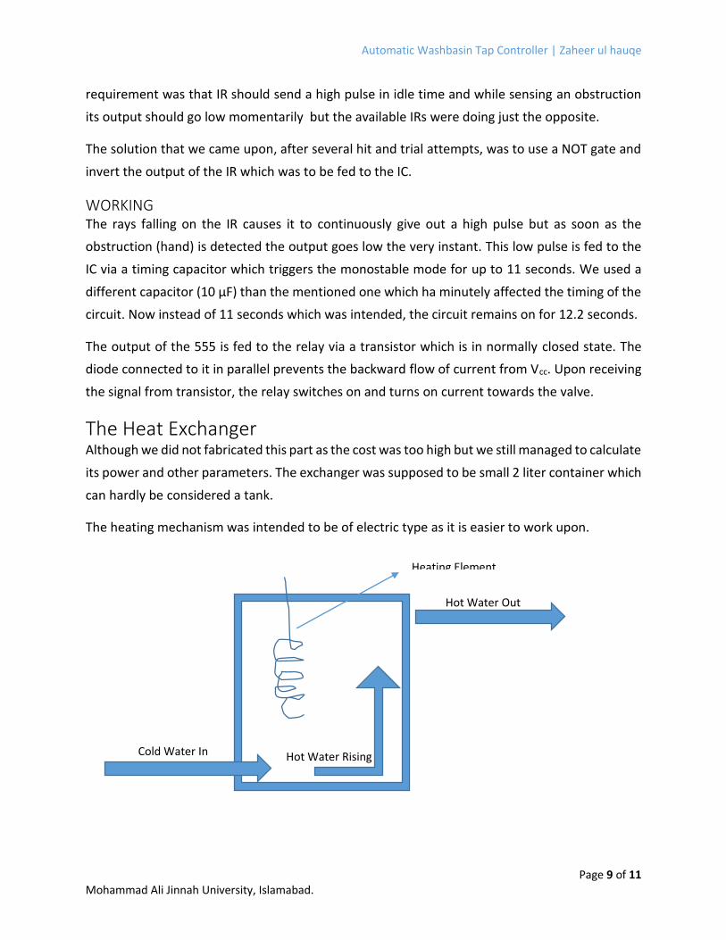
The Heat Exchanger Although we did not fabricated this part as the cost was too high but we still managed to calculate
its power and other parameters. The exchanger was supposed to be small 2 liter container which
can hardly be considered a tank.
The heating mechanism was intended to be of electric type as it is easier to work upon.
Cold Water In
Heating Element
Hot Water Out
Hot Water Rising

Automatic Washbasin Tap Controller | Zaheer ul hauqe
Page 10 of 11 Mohammad Ali Jinnah University, Islamabad.
WORKING The Heating element which would be triggered by a flow sensor fitted on the pipe assuring the
flow of water and eliminating the risk of dry heating that may occur due to any reason was
intended to be electrical. I made the calculations based on the flow rate of my dorm’s washrooms
water supply which experimentally came out to be 0.1 liter per second. As 𝜌 = 𝑚 𝑉⁄ and ρ being
1000 kg/m3 for water the mass rate came out to be 1 kilogram per second. Now from
𝑄 = 𝑚𝑐∆𝑇
Where Q is heat energy in joules, m, the mass of water, c being the specific heat of water and
∆𝑇 the desired temperature difference, I calculated my heat element to be of 2 KW. The
calculations are given below.
𝑄 = 𝑚𝑐∆𝑇
𝑄 = 1 𝑘𝑔 × 4186 𝑗
𝑘𝑔. °𝐶× 50 °𝐶
𝑄 = 209300 𝑗
Or
𝑄 = 209 𝐾𝑗
Shuffling the units you will get 2 KWh which is the optimum power element required to create a
positive difference of 50°C in temperature of 0.1 liter of water every second.
CONCLUSION This project was really interesting and enabled us to work outside our line of work. Practical
implementation of textbook concepts is very different dimension which is yet to be mastered
by us. It is these projects that helps us in doing so. This project removed the stereotyped idea
that, we the students of Mechanical engineering shouldn’t be studying electronics.
The world cannot be divided into different fields and to achieve success all the laws of physics
and the fields of engineering must work in a harmony so that us and our fellow humans can live
a better life and an elevated living standard.
Automatic Washbasin Tap Controller | Zaheer ul hauqe
Page 11 of 11 Mohammad Ali Jinnah University, Islamabad.
BIBILIOGRAPHY http://www.technologystudent.com/elec1/5554.htm
http://www.instructables.com/id/555-Timer/step2/555-Timer-Monostable-Mode/
http://www.allaboutcircuits.com/vol_6/chpt_8/4.html
http://www.dummies.com/how-to/content/electronics-components-how-the-555-
timer-chip-work.html
http://www.doctronics.co.uk/555.htm
http://www.technologystudent.com/elec1/5555.htm
http://www.instructables.com/id/555-Timer/step5/555-Timer-Astable-Mode/
http://maritime.org/doc/fleetsub/refrig/img/fig7-11.jpg
http://www.answers.com/topic/infrared-receiver
http://media3.rsdelivers.cataloguesolutions.com/LargeProductImages/RF286142-01.jpg
http://en.wikipedia.org/wiki/Solenoid_valve
http://www.solenoid-valve-info.com/solenoid-valve-basics.html
http://www.ask.com/question/how-does-a-solenoid-valve-work
https://www.futureelectronics.com/en/optoelectronics/infrared-receivers.aspx


![Read the words : [w] wall washbasin wardrobe window [ei] table bookcase washbasin painting](https://img.pdfslide.net/doc/110x75/56649f4f5503460f94c71339/read-the-words-w-wall-washbasin-wardrobe-window-ei-table-bookcase-washbasin.jpg)