Embed Size (px)
Citation preview

Automation Catalogue
We build the best automation products on the market right here in the Turkey and we stand behind them. We will outlast and outperform anyone on the market, and support to improve your system.
Made in Turkey
Klemsan Automation, supported by an experienced sales and technical team and an easy-to use software, is the adaptable alternative for any automation solution. Klemsan Automation is the perfect solution for any customized or demanding need.These products are specif ically suited for integration in a wide range of applications such as waste and water treatment, access control, renewable energies, building equipment, industrial machines and transportation.
short view
Automation Catalogue
KLEMSAN Automation
3

Automation Catalogue
Save your time and energy with fast response
Analysis of
customer requirements
Maximumdependability
Simple and effective functions suitable for your application
Logistics and After Sales Service
100%CustomerSatisfaction
Behind every project technologies and expertise
your success is our business
5
Automation Catalogue
contents
7
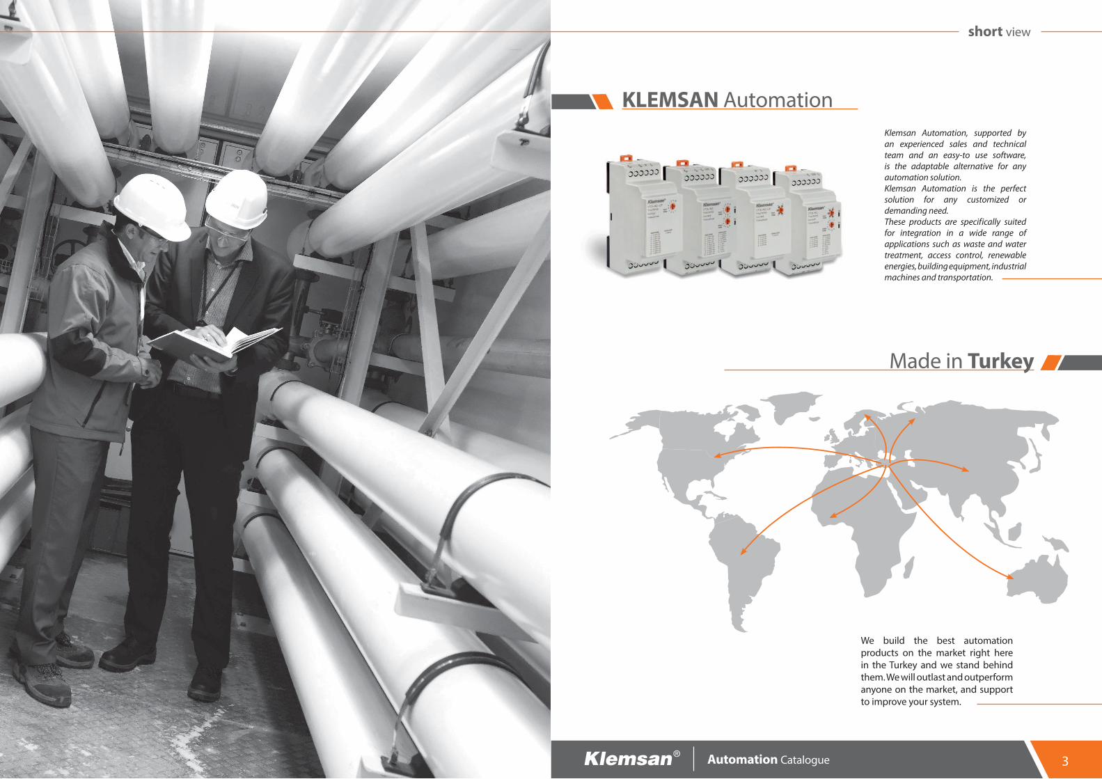
Time & Control Management Solutions
09
Alarm Management Solutions
41
Analog SignalManagement Solutions
57
Switching Management Solutions
79
Protection Management Solutions
23
Energy Monitoring Solutions
101
Communication Management Solutions
89
Reactive Power Management Solutions
121

Automation Catalogue
Timing is everything
Time & Control Management Solutions
9

A timer is an automation device that either keeps track of how much time has been spent doing something or that counts down a specif ied duration of time. After a predef inedtime has elapsed, the timer closes or opens its contact.
A timer can be used to start an action according to a predef ined time or stop an action over a period of time. It can also add delay an action. It allows to control applications with its trigger input as well.
Def ining a timer in simple terms
Which actions are executed?
Which markets are they used frequently?
StoppingDelaying
TriggeringStarting
l Industrial Machinesl Illuminatingl Construction industryl HVAC systemsl Food and agriculture industry
The Fundamentals
Automation Catalogue
Benef its and Advantagesl High accuracy and switching reliabilityl Sensitive timing range from 0.1sec to 10daysl High mechanical endurancel Multifunctional operating modesl Trigger inputl High level of Electromagnetic compatibility (EMC) i.e. maximum immunity to interferences.l A widely range of power supply from (24 to 300VAC/DC)l Sleek 17.5mm wide housing and compact design saves panel space.l Perfect to f it in Modular Enclosurel Protection against over voltage and reverse polarityl Self-Extinguishing plastic housing
Time & Control Management Solutions
Layout & MountingKlemsan electronic timers are suitable for snap mounting onto 35 mm standards DIN rails.
Trigger Input
Relay Output
Timing Range
Time Setting
Output Modes
Power Input
LED to indicate relay energized
LEDs to indicate operating modes
LED to indicate relay switched
T1-K Multifunctional Timer
11

Managing the operation of a conveyor belt based on the time interval between products on the belt.
Managing maintenance of the power supply in the event of amains power failure, switching on an external backup powersource for a given time.
Controlling flashing on lighted signs.
Automatic management of vending machines.
Timer T1 series
Timer T1 series
Timer T1-Flash, T1-M4, T1-M5
Timer T1-K
Conveyor Control
Remote Machinery Control
Smart Lighting
Vending Machines
Automation Catalogue
Applications Time & Control Management Solutions
Controls the direction of the motor’s rotation.
TIMER T1-LR
Direction Control of Industrial Motor
Succesfull run-up for industrial motors with star-delta relay.
Motor Starter Relay SD1
Star-Delta Starter
It can be used to control the liquid level in a tank. Sensitivity resistance can be adjusted thus there is no need to change models to match different liquid types and concentrations.
Liquid Level Controller LC3
Controlling Liquid Level in a Tank
Controlling billboards and street lights with the accurate and precise time thanks to photocell relay.
Photocell Relay PH1-20L
Billboard and Street Lighting
Controlling heat sealing times on blister packs, packaging bags, etc.
Timer T1-K, T1-M5, T1-M4
Packing Machine / System
13
Automation Catalogue
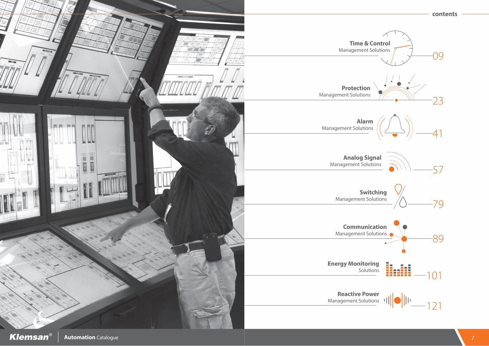
Type T1-60S T1-100S T1-XS T1-FLASH T1-M4 Z1-M5 T1-M5 T1-K T1-LR SD1 PH1-20L LC3
Timing Function Single-functional Single-functional Single-functional Single-functional Multifunctional Multifunctional Multifunctional Multifunctional Single-functional Single-functional Single-functional Single-functional
Def initon On delay timer On delay timer On delay timer Off flasher timer Multimode timer Multimode timer Multimode timer Multimode timer
with trigger input Left-right timer Star-delta timerPhotocell relay with an external photocell sensor
Liquid level con-troller
Order Number 270350 270359 270357 270351 270355 270373 270353 270354 270356 270358 270050 270001
Casing Width(mm) 17.5 17.5 17.5 17.5 17.5 17.5 17.5 17.5 17.5 17.5 17.5 36
Connections Screw terminal Screw terminal Screw terminal Screw terminal Screw terminal Screw terminal Screw terminal Screw terminal Screw terminal Screw terminal Screw terminal Screw terminal
Functions ND ND XS Foff ND,FD,Fon,Foff ND,FD,NFD, Fon,Foff
ND,FD,NFD, Fon,Foff a,b,c,d,e,f,g,h,i,k LR SD PHL LC
Type of Output Relay Relay Relay Relay Relay Relay Relay Relay Two Relays Two Relays Relay Relay
Auxiliarycontacts
Type 1 C/O (SPDT) 1 C/O (SPDT) 1 C/O (SPDT) 1 C/O (SPDT) 1 C/O (SPDT) 1 C/O (SPDT) 1 C/O (SPDT) 1 C/O (SPDT) 2 x C/O 2 x C/O 1 C/O (SPDT) 1 C/O (SPDT)
Max ratings-AC (for NO side)
5A/250V; 1250 VA
5A/250V; 1250 VA
5A/250V; 1250 VA
5A/250V; 1250 VA
5A/250V; 1250 VA
5A/250V; 1250 VA
5A/250V; 1250 VA
5A/250V; 1250 VA
5A/250V; 1250 VA
5A/250V; 1250 VA
5A/250V; 1250 VA 5A/250V; 1250 VA
Max ratings-DC (for NO side) 5A/30VDC; 150W 5A/30VDC; 150W 5A/30VDC; 150W 5A/30VDC; 150W 5A/30VDC;
150W 5A/30VDC; 150W 5A/30VDC; 150W 5A/30VDC; 150W 5A/30VDC; 150W 5A/30VDC; 150W 5A/30VDC; 150W 5A/30VDC; 150W
Mechanical life time ≥ 107 operations ≥ 107 operations ≥ 107 operations ≥ 107 operations ≥ 107 operations ≥ 107 operations ≥ 107 operations ≥ 107 operations ≥ 107 operations ≥ 107 operations ≥ 107 operations ≥ 107 operations
Electrical life timeoperations (for NO side)
5×10⁴(5A@250VAC) 1×10⁵(5A@30VDC)
5×10⁴(5A@250VAC) 1×10⁵(5A@30VDC)
5×10⁴(5A@250VAC) 1×10⁵(5A@30VDC)
5×10⁴(5A@250VAC) 1×10⁵(5A@30VDC)
5×10⁴(5A@250VAC) 1×10⁵(5A@30VDC)
5×10⁴(5A@250VAC) 1×10⁵(5A@30VDC)
5×10⁴(5A@250VAC) 1×10⁵(5A@30VDC)
5×10⁴(5A@250VAC) 1×10⁵(5A@30VDC)
5×10⁴(5A@250VAC) 1×10⁵(5A@30VDC)
5×10⁴(5A@250VAC) 1×10⁵(5A@30VDC)
5×10⁴(5A@250VAC) 1×10⁵(5A@30VDC)
5×10⁴(5A@250VAC) 1×10⁵(5A@30VDC)
Adjustment of Timing-1 & Timing-2 - - - independent independent dependent dependent - independent independent independent -
Time RangeTiming-1 1s =>60s 1s =>100s 1s =>2559s 0.1s =>10d 1s =>10d 0.1s =>10d 0.1s =>10d 0.1s =>10d 0.1s =>10d 1s =>30s 1s =>45s 0.1s =>1s
Timing-2 - - - 0.1s =>10d 1s =>10d 0.1s =>10d 0.1s =>10d - 0.1s =>10d 20ms=>500ms 1s =>45s -
Lux adjustment range - - - - - - - - - - 1-20Lux -
Sensitivity adjustment range - - - - - - - - - - - 5-100kΩ
Supply VoltageDC 24-300 VDC 24VDC 24-300 VDC 24-300 VDC 24-300 VDC 12VDC 24-300 VDC 24-300 VDC 24-300 VDC - 24-300 VDC -
AC 24-300 VAC 24VAC or 180-265 VAC 24-300 VAC 24-300 VAC 24-300 VAC 12VAC or
180-265 VAC 24-300 VAC 24-300 VAC 24-300 VAC 150-500 VAC 24-300 VAC 150-500 VAC
Supply Frequency 35-70 Hz 35-70 Hz 35-70 Hz 35-70 Hz 35-70 Hz 35-70 Hz 35-70 Hz 35-70 Hz 35-70 Hz 35-70 Hz 35-70 Hz 35-70 Hz
Trigger Input Voltage - - - - - - - 24-300 VAC/DC - - - -
Permissibleambient temperature
During operation -20 to +60 °C -20 to +60 °C -20 to +60 °C -20 to +60 °C -20 to +60 °C -20 to +60 °C -20 to +60 °C -20 to +60 °C -20 to +60 °C -20 to +60 °C -20 to +60 °C -20 to +60 °C
During storage -40 to +75 °C -40 to +75 °C -40 to +75 °C -40 to +75 °C -40 to +75 °C -40 to +75 °C -40 to +75 °C -40 to +75 °C -40 to +75 °C -40 to +75 °C -40 to +75 °C -40 to +75 °C
Relative Humidity Max. 95% (no condensation)
Max. 95% (no condensation
Max. 95% (no condensation
Max. 95% (no condensation
Max. 95% (no condensation
Max. 95% (no condensation
Max. 95% (no condensation
Max. 95% (no condensation
Max. 95% (no condensation
Max. 95% (no condensation
Max. 95% (no condensation
Max. 95% (no con-densation
Recovery time Max. 100ms Max. 100ms Max. 100ms Max. 100ms Max. 100ms Max. 100ms Max. 100ms Max. 100ms Max. 100ms Max. 100ms Max. 100ms Max. 100ms
Degree of protection IP20 IP20 IP20 IP20 IP20 IP20 IP20 IP20 IP20 IP20 IP20 IP20
Powerconsumption
DC <1.25W <1W <1.25W <1.25W <1.25W <1.25W <1.25W <1.25W <1.25W <1.25W <1.25W -
AC <2.5VA <13VA <2.5VA <2.5VA <2.5VA <2.5VA <2.5VA <2.5VA <2.5VA <2.5VA <2.5VA <7VA
Weight(gr) 57 57 62 60 60 60 60 66 70 70 63 82
Selection & Ordering Guide Time & Control Management Solutions
Type T1-60S T1-100S T1-XS T1-FLASH T1-M4 Z1-M5 T1-M5 T1-K T1-LR SD1 PH1-20L LC3
Timing Function Single-functional Single-functional Single-functional Single-functional Multifunctional Multifunctional Multifunctional Multifunctional Single-functional Single-functional Single-functional Single-functional
Def initon On delay timer On delay timer On delay timer Off flasher timer Multimode timer Multimode timer Multimode timer Multimode timer
with trigger input Left-right timer Star-delta timerPhotocell relay with an external photocell sensor
Liquid level con-troller
Order Number 270350 270359 270357 270351 270355 270373 270353 270354 270356 270358 270050 270001
Casing Width(mm) 17.5 17.5 17.5 17.5 17.5 17.5 17.5 17.5 17.5 17.5 17.5 36
Connections Screw terminal Screw terminal Screw terminal Screw terminal Screw terminal Screw terminal Screw terminal Screw terminal Screw terminal Screw terminal Screw terminal Screw terminal
Functions ND ND XS Foff ND,FD,Fon,Foff ND,FD,NFD, Fon,Foff
ND,FD,NFD, Fon,Foff a,b,c,d,e,f,g,h,i,k LR SD PHL LC
Type of Output Relay Relay Relay Relay Relay Relay Relay Relay Two Relays Two Relays Relay Relay
Auxiliarycontacts
Type 1 C/O (SPDT) 1 C/O (SPDT) 1 C/O (SPDT) 1 C/O (SPDT) 1 C/O (SPDT) 1 C/O (SPDT) 1 C/O (SPDT) 1 C/O (SPDT) 2 x C/O 2 x C/O 1 C/O (SPDT) 1 C/O (SPDT)
Max ratings-AC (for NO side)
5A/250V; 1250 VA
5A/250V; 1250 VA
5A/250V; 1250 VA
5A/250V; 1250 VA
5A/250V; 1250 VA
5A/250V; 1250 VA
5A/250V; 1250 VA
5A/250V; 1250 VA
5A/250V; 1250 VA
5A/250V; 1250 VA
5A/250V; 1250 VA 5A/250V; 1250 VA
Max ratings-DC (for NO side) 5A/30VDC; 150W 5A/30VDC; 150W 5A/30VDC; 150W 5A/30VDC; 150W 5A/30VDC;
150W 5A/30VDC; 150W 5A/30VDC; 150W 5A/30VDC; 150W 5A/30VDC; 150W 5A/30VDC; 150W 5A/30VDC; 150W 5A/30VDC; 150W
Mechanical life time ≥ 107 operations ≥ 107 operations ≥ 107 operations ≥ 107 operations ≥ 107 operations ≥ 107 operations ≥ 107 operations ≥ 107 operations ≥ 107 operations ≥ 107 operations ≥ 107 operations ≥ 107 operations
Electrical life timeoperations (for NO side)
5×10⁴(5A@250VAC) 1×10⁵(5A@30VDC)
5×10⁴(5A@250VAC) 1×10⁵(5A@30VDC)
5×10⁴(5A@250VAC) 1×10⁵(5A@30VDC)
5×10⁴(5A@250VAC) 1×10⁵(5A@30VDC)
5×10⁴(5A@250VAC) 1×10⁵(5A@30VDC)
5×10⁴(5A@250VAC) 1×10⁵(5A@30VDC)
5×10⁴(5A@250VAC) 1×10⁵(5A@30VDC)
5×10⁴(5A@250VAC) 1×10⁵(5A@30VDC)
5×10⁴(5A@250VAC) 1×10⁵(5A@30VDC)
5×10⁴(5A@250VAC) 1×10⁵(5A@30VDC)
5×10⁴(5A@250VAC) 1×10⁵(5A@30VDC)
5×10⁴(5A@250VAC) 1×10⁵(5A@30VDC)
Adjustment of Timing-1 & Timing-2 - - - independent independent dependent dependent - independent independent independent -
Time RangeTiming-1 1s =>60s 1s =>100s 1s =>2559s 0.1s =>10d 1s =>10d 0.1s =>10d 0.1s =>10d 0.1s =>10d 0.1s =>10d 1s =>30s 1s =>45s 0.1s =>1s
Timing-2 - - - 0.1s =>10d 1s =>10d 0.1s =>10d 0.1s =>10d - 0.1s =>10d 20ms=>500ms 1s =>45s -
Lux adjustment range - - - - - - - - - - 1-20Lux -
Sensitivity adjustment range - - - - - - - - - - - 5-100kΩ
Supply VoltageDC 24-300 VDC 24VDC 24-300 VDC 24-300 VDC 24-300 VDC 12VDC 24-300 VDC 24-300 VDC 24-300 VDC - 24-300 VDC -
AC 24-300 VAC 24VAC or 180-265 VAC 24-300 VAC 24-300 VAC 24-300 VAC 12VAC or
180-265 VAC 24-300 VAC 24-300 VAC 24-300 VAC 150-500 VAC 24-300 VAC 150-500 VAC
Supply Frequency 35-70 Hz 35-70 Hz 35-70 Hz 35-70 Hz 35-70 Hz 35-70 Hz 35-70 Hz 35-70 Hz 35-70 Hz 35-70 Hz 35-70 Hz 35-70 Hz
Trigger Input Voltage - - - - - - - 24-300 VAC/DC - - - -
Permissibleambient temperature
During operation -20 to +60 °C -20 to +60 °C -20 to +60 °C -20 to +60 °C -20 to +60 °C -20 to +60 °C -20 to +60 °C -20 to +60 °C -20 to +60 °C -20 to +60 °C -20 to +60 °C -20 to +60 °C
During storage -40 to +75 °C -40 to +75 °C -40 to +75 °C -40 to +75 °C -40 to +75 °C -40 to +75 °C -40 to +75 °C -40 to +75 °C -40 to +75 °C -40 to +75 °C -40 to +75 °C -40 to +75 °C
Relative Humidity Max. 95% (no condensation)
Max. 95% (no condensation
Max. 95% (no condensation
Max. 95% (no condensation
Max. 95% (no condensation
Max. 95% (no condensation
Max. 95% (no condensation
Max. 95% (no condensation
Max. 95% (no condensation
Max. 95% (no condensation
Max. 95% (no condensation
Max. 95% (no con-densation
Recovery time Max. 100ms Max. 100ms Max. 100ms Max. 100ms Max. 100ms Max. 100ms Max. 100ms Max. 100ms Max. 100ms Max. 100ms Max. 100ms Max. 100ms
Degree of protection IP20 IP20 IP20 IP20 IP20 IP20 IP20 IP20 IP20 IP20 IP20 IP20
Powerconsumption
DC <1.25W <1W <1.25W <1.25W <1.25W <1.25W <1.25W <1.25W <1.25W <1.25W <1.25W -
AC <2.5VA <13VA <2.5VA <2.5VA <2.5VA <2.5VA <2.5VA <2.5VA <2.5VA <2.5VA <2.5VA <7VA
Weight(gr) 57 57 62 60 60 60 60 66 70 70 63 82
15Automation Catalogue
Type T1-60S T1-100S T1-XS T1-FLASH T1-M4 Z1-M5 T1-M5 T1-K T1-LR SD1 PH1-20L LC3
Timing Function Single-functional Single-functional Single-functional Single-functional Multifunctional Multifunctional Multifunctional Multifunctional Single-functional Single-functional Single-functional Single-functional
Def initon On delay timer On delay timer On delay timer Off flasher timer Multimode timer Multimode timer Multimode timer Multimode timer
with trigger input Left-right timer Star-delta timerPhotocell relay with an external photocell sensor
Liquid level con-troller
Order Number 270350 270359 270357 270351 270355 270373 270353 270354 270356 270358 270050 270001
Casing Width(mm) 17.5 17.5 17.5 17.5 17.5 17.5 17.5 17.5 17.5 17.5 17.5 36
Connections Screw terminal Screw terminal Screw terminal Screw terminal Screw terminal Screw terminal Screw terminal Screw terminal Screw terminal Screw terminal Screw terminal Screw terminal
Functions ND ND XS Foff ND,FD,Fon,Foff ND,FD,NFD, Fon,Foff
ND,FD,NFD, Fon,Foff a,b,c,d,e,f,g,h,i,k LR SD PHL LC
Type of Output Relay Relay Relay Relay Relay Relay Relay Relay Two Relays Two Relays Relay Relay
Auxiliarycontacts
Type 1 C/O (SPDT) 1 C/O (SPDT) 1 C/O (SPDT) 1 C/O (SPDT) 1 C/O (SPDT) 1 C/O (SPDT) 1 C/O (SPDT) 1 C/O (SPDT) 2 x C/O 2 x C/O 1 C/O (SPDT) 1 C/O (SPDT)
Max ratings-AC (for NO side)
5A/250V; 1250 VA
5A/250V; 1250 VA
5A/250V; 1250 VA
5A/250V; 1250 VA
5A/250V; 1250 VA
5A/250V; 1250 VA
5A/250V; 1250 VA
5A/250V; 1250 VA
5A/250V; 1250 VA
5A/250V; 1250 VA
5A/250V; 1250 VA 5A/250V; 1250 VA
Max ratings-DC (for NO side) 5A/30VDC; 150W 5A/30VDC; 150W 5A/30VDC; 150W 5A/30VDC; 150W 5A/30VDC;
150W 5A/30VDC; 150W 5A/30VDC; 150W 5A/30VDC; 150W 5A/30VDC; 150W 5A/30VDC; 150W 5A/30VDC; 150W 5A/30VDC; 150W
Mechanical life time ≥ 107 operations ≥ 107 operations ≥ 107 operations ≥ 107 operations ≥ 107 operations ≥ 107 operations ≥ 107 operations ≥ 107 operations ≥ 107 operations ≥ 107 operations ≥ 107 operations ≥ 107 operations
Electrical life timeoperations (for NO side)
5×10⁴(5A@250VAC) 1×10⁵(5A@30VDC)
5×10⁴(5A@250VAC) 1×10⁵(5A@30VDC)
5×10⁴(5A@250VAC) 1×10⁵(5A@30VDC)
5×10⁴(5A@250VAC) 1×10⁵(5A@30VDC)
5×10⁴(5A@250VAC) 1×10⁵(5A@30VDC)
5×10⁴(5A@250VAC) 1×10⁵(5A@30VDC)
5×10⁴(5A@250VAC) 1×10⁵(5A@30VDC)
5×10⁴(5A@250VAC) 1×10⁵(5A@30VDC)
5×10⁴(5A@250VAC) 1×10⁵(5A@30VDC)
5×10⁴(5A@250VAC) 1×10⁵(5A@30VDC)
5×10⁴(5A@250VAC) 1×10⁵(5A@30VDC)
5×10⁴(5A@250VAC) 1×10⁵(5A@30VDC)
Adjustment of Timing-1 & Timing-2 - - - independent independent dependent dependent - independent independent independent -
Time RangeTiming-1 1s =>60s 1s =>100s 1s =>2559s 0.1s =>10d 1s =>10d 0.1s =>10d 0.1s =>10d 0.1s =>10d 0.1s =>10d 1s =>30s 1s =>45s 0.1s =>1s
Timing-2 - - - 0.1s =>10d 1s =>10d 0.1s =>10d 0.1s =>10d - 0.1s =>10d 20ms=>500ms 1s =>45s -
Lux adjustment range - - - - - - - - - - 1-20Lux -
Sensitivity adjustment range - - - - - - - - - - - 5-100kΩ
Supply VoltageDC 24-300 VDC 24VDC 24-300 VDC 24-300 VDC 24-300 VDC 12VDC 24-300 VDC 24-300 VDC 24-300 VDC - 24-300 VDC -
AC 24-300 VAC 24VAC or 180-265 VAC 24-300 VAC 24-300 VAC 24-300 VAC 12VAC or
180-265 VAC 24-300 VAC 24-300 VAC 24-300 VAC 150-500 VAC 24-300 VAC 150-500 VAC
Supply Frequency 35-70 Hz 35-70 Hz 35-70 Hz 35-70 Hz 35-70 Hz 35-70 Hz 35-70 Hz 35-70 Hz 35-70 Hz 35-70 Hz 35-70 Hz 35-70 Hz
Trigger Input Voltage - - - - - - - 24-300 VAC/DC - - - -
Permissibleambient temperature
During operation -20 to +60 °C -20 to +60 °C -20 to +60 °C -20 to +60 °C -20 to +60 °C -20 to +60 °C -20 to +60 °C -20 to +60 °C -20 to +60 °C -20 to +60 °C -20 to +60 °C -20 to +60 °C
During storage -40 to +75 °C -40 to +75 °C -40 to +75 °C -40 to +75 °C -40 to +75 °C -40 to +75 °C -40 to +75 °C -40 to +75 °C -40 to +75 °C -40 to +75 °C -40 to +75 °C -40 to +75 °C
Relative Humidity Max. 95% (no condensation)
Max. 95% (no condensation
Max. 95% (no condensation
Max. 95% (no condensation
Max. 95% (no condensation
Max. 95% (no condensation
Max. 95% (no condensation
Max. 95% (no condensation
Max. 95% (no condensation
Max. 95% (no condensation
Max. 95% (no condensation
Max. 95% (no con-densation
Recovery time Max. 100ms Max. 100ms Max. 100ms Max. 100ms Max. 100ms Max. 100ms Max. 100ms Max. 100ms Max. 100ms Max. 100ms Max. 100ms Max. 100ms
Degree of protection IP20 IP20 IP20 IP20 IP20 IP20 IP20 IP20 IP20 IP20 IP20 IP20
Powerconsumption
DC <1.25W <1W <1.25W <1.25W <1.25W <1.25W <1.25W <1.25W <1.25W <1.25W <1.25W -
AC <2.5VA <13VA <2.5VA <2.5VA <2.5VA <2.5VA <2.5VA <2.5VA <2.5VA <2.5VA <2.5VA <7VA
Weight(gr) 57 57 62 60 60 60 60 66 70 70 63 82
Selection & Ordering Guide Time & Control Management Solutions
Type T1-60S T1-100S T1-XS T1-FLASH T1-M4 Z1-M5 T1-M5 T1-K T1-LR SD1 PH1-20L LC3
Timing Function Single-functional Single-functional Single-functional Single-functional Multifunctional Multifunctional Multifunctional Multifunctional Single-functional Single-functional Single-functional Single-functional
Def initon On delay timer On delay timer On delay timer Off flasher timer Multimode timer Multimode timer Multimode timer Multimode timer
with trigger input Left-right timer Star-delta timerPhotocell relay with an external photocell sensor
Liquid level con-troller
Order Number 270350 270359 270357 270351 270355 270373 270353 270354 270356 270358 270050 270001
Casing Width(mm) 17.5 17.5 17.5 17.5 17.5 17.5 17.5 17.5 17.5 17.5 17.5 36
Connections Screw terminal Screw terminal Screw terminal Screw terminal Screw terminal Screw terminal Screw terminal Screw terminal Screw terminal Screw terminal Screw terminal Screw terminal
Functions ND ND XS Foff ND,FD,Fon,Foff ND,FD,NFD, Fon,Foff
ND,FD,NFD, Fon,Foff a,b,c,d,e,f,g,h,i,k LR SD PHL LC
Type of Output Relay Relay Relay Relay Relay Relay Relay Relay Two Relays Two Relays Relay Relay
Auxiliarycontacts
Type 1 C/O (SPDT) 1 C/O (SPDT) 1 C/O (SPDT) 1 C/O (SPDT) 1 C/O (SPDT) 1 C/O (SPDT) 1 C/O (SPDT) 1 C/O (SPDT) 2 x C/O 2 x C/O 1 C/O (SPDT) 1 C/O (SPDT)
Max ratings-AC (for NO side)
5A/250V; 1250 VA
5A/250V; 1250 VA
5A/250V; 1250 VA
5A/250V; 1250 VA
5A/250V; 1250 VA
5A/250V; 1250 VA
5A/250V; 1250 VA
5A/250V; 1250 VA
5A/250V; 1250 VA
5A/250V; 1250 VA
5A/250V; 1250 VA 5A/250V; 1250 VA
Max ratings-DC (for NO side) 5A/30VDC; 150W 5A/30VDC; 150W 5A/30VDC; 150W 5A/30VDC; 150W 5A/30VDC;
150W 5A/30VDC; 150W 5A/30VDC; 150W 5A/30VDC; 150W 5A/30VDC; 150W 5A/30VDC; 150W 5A/30VDC; 150W 5A/30VDC; 150W
Mechanical life time ≥ 107 operations ≥ 107 operations ≥ 107 operations ≥ 107 operations ≥ 107 operations ≥ 107 operations ≥ 107 operations ≥ 107 operations ≥ 107 operations ≥ 107 operations ≥ 107 operations ≥ 107 operations
Electrical life timeoperations (for NO side)
5×10⁴(5A@250VAC) 1×10⁵(5A@30VDC)
5×10⁴(5A@250VAC) 1×10⁵(5A@30VDC)
5×10⁴(5A@250VAC) 1×10⁵(5A@30VDC)
5×10⁴(5A@250VAC) 1×10⁵(5A@30VDC)
5×10⁴(5A@250VAC) 1×10⁵(5A@30VDC)
5×10⁴(5A@250VAC) 1×10⁵(5A@30VDC)
5×10⁴(5A@250VAC) 1×10⁵(5A@30VDC)
5×10⁴(5A@250VAC) 1×10⁵(5A@30VDC)
5×10⁴(5A@250VAC) 1×10⁵(5A@30VDC)
5×10⁴(5A@250VAC) 1×10⁵(5A@30VDC)
5×10⁴(5A@250VAC) 1×10⁵(5A@30VDC)
5×10⁴(5A@250VAC) 1×10⁵(5A@30VDC)
Adjustment of Timing-1 & Timing-2 - - - independent independent dependent dependent - independent independent independent -
Time RangeTiming-1 1s =>60s 1s =>100s 1s =>2559s 0.1s =>10d 1s =>10d 0.1s =>10d 0.1s =>10d 0.1s =>10d 0.1s =>10d 1s =>30s 1s =>45s 0.1s =>1s
Timing-2 - - - 0.1s =>10d 1s =>10d 0.1s =>10d 0.1s =>10d - 0.1s =>10d 20ms=>500ms 1s =>45s -
Lux adjustment range - - - - - - - - - - 1-20Lux -
Sensitivity adjustment range - - - - - - - - - - - 5-100kΩ
Supply VoltageDC 24-300 VDC 24VDC 24-300 VDC 24-300 VDC 24-300 VDC 12VDC 24-300 VDC 24-300 VDC 24-300 VDC - 24-300 VDC -
AC 24-300 VAC 24VAC or 180-265 VAC 24-300 VAC 24-300 VAC 24-300 VAC 12VAC or
180-265 VAC 24-300 VAC 24-300 VAC 24-300 VAC 150-500 VAC 24-300 VAC 150-500 VAC
Supply Frequency 35-70 Hz 35-70 Hz 35-70 Hz 35-70 Hz 35-70 Hz 35-70 Hz 35-70 Hz 35-70 Hz 35-70 Hz 35-70 Hz 35-70 Hz 35-70 Hz
Trigger Input Voltage - - - - - - - 24-300 VAC/DC - - - -
Permissibleambient temperature
During operation -20 to +60 °C -20 to +60 °C -20 to +60 °C -20 to +60 °C -20 to +60 °C -20 to +60 °C -20 to +60 °C -20 to +60 °C -20 to +60 °C -20 to +60 °C -20 to +60 °C -20 to +60 °C
During storage -40 to +75 °C -40 to +75 °C -40 to +75 °C -40 to +75 °C -40 to +75 °C -40 to +75 °C -40 to +75 °C -40 to +75 °C -40 to +75 °C -40 to +75 °C -40 to +75 °C -40 to +75 °C
Relative Humidity Max. 95% (no condensation)
Max. 95% (no condensation
Max. 95% (no condensation
Max. 95% (no condensation
Max. 95% (no condensation
Max. 95% (no condensation
Max. 95% (no condensation
Max. 95% (no condensation
Max. 95% (no condensation
Max. 95% (no condensation
Max. 95% (no condensation
Max. 95% (no con-densation
Recovery time Max. 100ms Max. 100ms Max. 100ms Max. 100ms Max. 100ms Max. 100ms Max. 100ms Max. 100ms Max. 100ms Max. 100ms Max. 100ms Max. 100ms
Degree of protection IP20 IP20 IP20 IP20 IP20 IP20 IP20 IP20 IP20 IP20 IP20 IP20
Powerconsumption
DC <1.25W <1W <1.25W <1.25W <1.25W <1.25W <1.25W <1.25W <1.25W <1.25W <1.25W -
AC <2.5VA <13VA <2.5VA <2.5VA <2.5VA <2.5VA <2.5VA <2.5VA <2.5VA <2.5VA <2.5VA <7VA
Weight(gr) 57 57 62 60 60 60 60 66 70 70 63 82
15

Permissible mounting position any any any any any any any any any any any any
EMC-EMI
55011/A1, 61000-4-2, 61000-4-3/A1, 61000-4-4, 61000-4-5, 61000-4-6, 61000-4-8,61000-4-11
OK OK OK OK OK - OK OK OK OK OK OK
Accessories
Def initon - - - - - - - - - - - Liquid Level probe for LC3
Order Number - - - - - - - - - - - 280610
Packaging unit - - - - - - - - - - - 1 pc.
Schematics
Dimensional Drawings
Type T1-60S T1-100S T1-XS T1-FLASH T1-M4 Z1-M5 T1-M5 T1-K T1-LR SD1 PH1-20L LC3
Automation Catalogue
Selection & Ordering Guide
LiquidLevel Electrode
Auxiliary Output
Supply Voltage
Auxiliary Output
Supply Voltage
Auxiliary Output
Supply Voltage
Auxiliary Output
Supply Voltage
Auxiliary Output
Supply VoltageOption-2
(180-265 VAC)
Supply Voltage
Option-1(24 VDC)
Permissible mounting position any any any any any any any any any any any any
EMC-EMI
55011/A1, 61000-4-2, 61000-4-3/A1, 61000-4-4, 61000-4-5, 61000-4-6, 61000-4-8,61000-4-11
OK OK OK OK OK - OK OK OK OK OK OK
Accessories
Def initon - - - - - - - - - - - Liquid Level probe for LC3
Order Number - - - - - - - - - - - 280610
Packaging unit - - - - - - - - - - - 1 pc.
Schematics
Dimensional Drawings
Type T1-60S T1-100S T1-XS T1-FLASH T1-M4 Z1-M5 T1-M5 T1-K T1-LR SD1 PH1-20L LC3
Time & Control Management Solutions
17
29.1mm
50.6mm57.5mm
45.5mm
62mm
90mm
36mm
Auxiliary Output
Supply Voltage
Auxiliary Output
Supply VoltageOption-2
(180-265 VAC)
Supply Voltage
Option-1(12 VAC/DC)
AuxiliaryOutput
Trigger Input
Supply Voltage
Supply Voltage
Auxiliary Output-1
Auxiliary Output-2
Auxiliary Output-1
Auxiliary Output-2
Supply Voltage
Auxiliary Output
Photocell Sensor
Photocell SensorInput
Supply Voltage
2
U2U1
1 3A B C
A
B
C
Supply Voltage
AuxiliaryOutput
ElectrodeInputs
Permissible mounting position any any any any any any any any any any any any
EMC-EMI
55011/A1, 61000-4-2, 61000-4-3/A1, 61000-4-4, 61000-4-5, 61000-4-6, 61000-4-8,61000-4-11
OK OK OK OK OK - OK OK OK OK OK OK
Accessories
Def initon - - - - - - - - - - - Liquid Level probe for LC3
Order Number - - - - - - - - - - - 280610
Packaging unit - - - - - - - - - - - 1 pc.
Schematics
Dimensional Drawings
Type T1-60S T1-100S T1-XS T1-FLASH T1-M4 Z1-M5 T1-M5 T1-K T1-LR SD1 PH1-20L LC3
Automation Catalogue
Selection & Ordering Guide
LiquidLevel Electrode
Auxiliary Output
Supply Voltage
Auxiliary Output
Supply Voltage
Auxiliary Output
Supply Voltage
Auxiliary Output
Supply Voltage
Auxiliary Output
Supply VoltageOption-2
(180-265 VAC)
Supply Voltage
Option-1(24 VDC)
Automation Catalogue
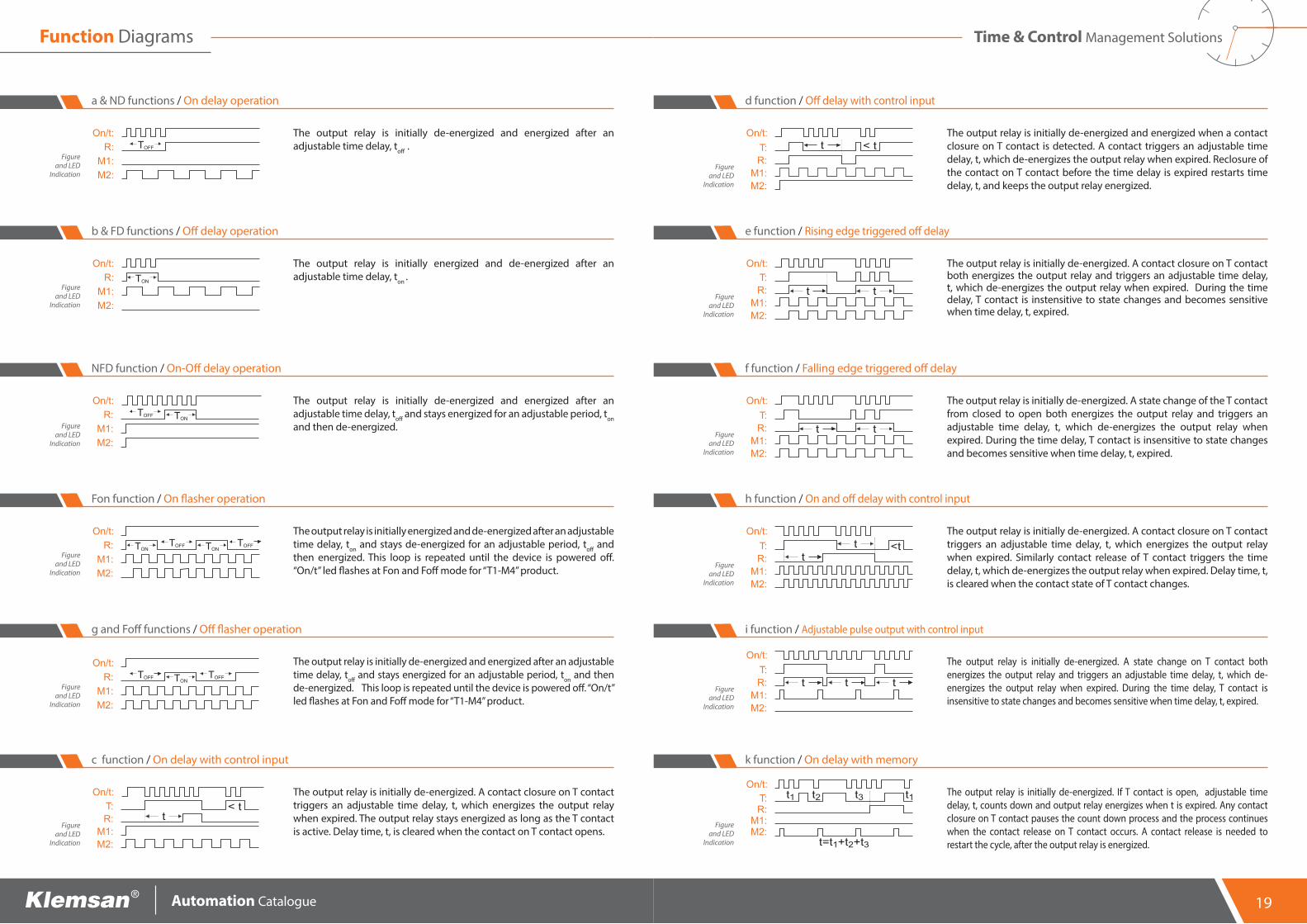
The output relay is initially de-energized and energized after an adjustable time delay, toff .
Figure and LED
Indication
a & ND functions / On delay operation
The output relay is initially energized and de-energized after an adjustable time delay, ton .
Figure and LED
Indication
b & FD functions / Off delay operation
The output relay is initially de-energized and energized after an adjustable time delay, toff and stays energized for an adjustable period, ton and then de-energized. Figure
and LED Indication
NFD function / On-Off delay operation
The output relay is initially energized and de-energized after an adjustable time delay, ton and stays de-energized for an adjustable period, toff and then energized. This loop is repeated until the device is powered off. “On/t” led flashes at Fon and Foff mode for “T1-M4” product.
Figure and LED
Indication
Fon function / On flasher operation
The output relay is initially de-energized and energized after an adjustable time delay, toff and stays energized for an adjustable period, ton and then de-energized. This loop is repeated until the device is powered off. “On/t” led flashes at Fon and Foff mode for “T1-M4” product.
Figure and LED
Indication
g and Foff functions / Off flasher operation
The output relay is initially de-energized. A contact closure on T contact triggers an adjustable time delay, t, which energizes the output relay when expired. The output relay stays energized as long as the T contact is active. Delay time, t, is cleared when the contact on T contact opens.
Figure and LED
Indication
c function / On delay with control input
Function Diagrams Time & Control Management Solutions
The output relay is initially de-energized and energized when a contact closure on T contact is detected. A contact triggers an adjustable time delay, t, which de-energizes the output relay when expired. Reclosure of the contact on T contact before the time delay is expired restarts time delay, t, and keeps the output relay energized.
Figure and LED
Indication
d function / Off delay with control input
The output relay is initially de-energized. A contact closure on T contact both energizes the output relay and triggers an adjustable time delay, t, which de-energizes the output relay when expired. During the time delay, T contact is instensitive to state changes and becomes sensitive when time delay, t, expired.
Figure and LED
Indication
e function / Rising edge triggered off delay
The output relay is initially de-energized. A state change of the T contact from closed to open both energizes the output relay and triggers an adjustable time delay, t, which de-energizes the output relay when expired. During the time delay, T contact is insensitive to state changes and becomes sensitive when time delay, t, expired.
Figure and LED
Indication
f function / Falling edge triggered off delay
The output relay is initially de-energized. A contact closure on T contact triggers an adjustable time delay, t, which energizes the output relay when expired. Similarly contact release of T contact triggers the time delay, t, which de-energizes the output relay when expired. Delay time, t, is cleared when the contact state of T contact changes.
Figure and LED
Indication
h function / On and off delay with control input
The output relay is initially de-energized. A state change on T contact both energizes the output relay and triggers an adjustable time delay, t, which de-energizes the output relay when expired. During the time delay, T contact is insensitive to state changes and becomes sensitive when time delay, t, expired.
Figure and LED
Indication
i function / Adjustable pulse output with control input
The output relay is initially de-energized. If T contact is open, adjustable time delay, t, counts down and output relay energizes when t is expired. Any contact closure on T contact pauses the count down process and the process continues when the contact release on T contact occurs. A contact release is needed to restart the cycle, after the output relay is energized.
Figure and LED
Indication
k function / On delay with memory
19

Automation Catalogue
T1-XS is an ON delay timer thet allows a sensitive time setting from 1 to 2559 seconds with 1 second increments. The output relay is initially de-energized and energized after the time delay t is expired.
Figure and LED
Indication
XS function / On delay adjustment for each second
When the energy applied to device, star relay is energized until the end of the adjustable time. At the end of the adjusted delay time , delta relay is energized until the device is powered off.
Figure and LED
Indication
SD function / Star-Delta operation
Initially f irst relay is energized. After the adjustable time delay ton , relay is de-energized. Both relays are de-energized during the adjustable time delay toff . At the end of toff , second relay energizes. Second relay stays in this position during ton . When ton f inished both relays are de-energized. This cycle is repeated continuously.
Figure and LED
Indication
Figure and LED
Indication
LR function / Left-Right operation
PH1-20L photocell relay measures the luminous intensity by means of a photocell sensor. On-off thereshold value is adjusted in the range of 1-20 lux, via the front adjustment dial. The output relay is energized when the ambient light level is below the adjusted limit. On and off delays are adjustable between 1 and 45 seconds, via the front panel knobs. On delay is adjusted by ton knob, and off delay is adjusted by toff knob.
PHL function / Photocell operation
Function Diagrams Time & Control Management Solutions
3 electrodes mode:When the level of liquid in the tank reaches to electrode B, the output relay is activated and stays in this position even if the level drops below the electrode B level. The output relay is deactivated when the liquid level drops below the electrode A level. Re-activation occurs when the level reaches to the electrode B level.
2 electrodes mode:For 2 electrodes mode of operation, A and B electrodes are used. When level of liquid in the tank reaches to electrode B, output relay is activated. When the liquid level drops below electrode B and continually stays there for the adjustable time delay (adjusted on the front panel knob); output relay will be de-energized.
Figure and LED Indication
LC function / Liquid Level Operation
21


AUTOMATION CATALOG (2015)6.6.4.2.1.00160
FactoryKemalpaşa Yolu 3. km 35170İZMİR / TURKEYTel: (+90 232) 877 08 00Fax: (+90 232) 877 08 06
Russian Federation141400, Khimki, Zavodskaya 2- MoscowTel : +7 495 644 02 21
U.A.EZ Building Z 57 Saif ZoneSharjahTel :+971 6-557 37 10Mobile :+971 56-760 28 37
Ukraine6-8A, Yaroslava Ivashkevicha Str.Office 7-8 04074, KievTel :+380 637 217 185
ColombiaMobile :+57 304 427 73 59
MexicoMobile :+52 (55) 4511 8809
www.klemsan.com.tr
ChinaSoho Plaza, 360 Hengtong Road, 20th Floor, Suite 20B04 Zip: 200070 ShanghaiTel :+86 21 62260338Fax :+86 21 62263983
USA255 West Martin Luther King Blvd.Unit 1511 28202 - Charlotte NC.Tel : +1 980 226 06 88
OVERSEAS OFFICES
Sales Head OfficePerpa A Blok K:2 No: 9/0041 Okmeydanı – İstanbul / TURKEYTel:+90 (212) 222 52 00Fax:+90 (212) 222 66 55
Rev
isio
n N
o: 1
2112
015