Embed Size (px)
Citation preview
A
PAPER ON
ENVIRONMENTAL FRIENDLY REFRIGERATION &
AIR CONDITIONING SYSTEM
SUBJECT:
AUTOMOBILE A/C BY UTILISING
WASTE HEAT & GASES
PRESENTED BY:
MS. KIRAN G. HORE
MS JYOTI S. KOTECHA
(MECHANICAL ENGINEERING)
JAWAHARLAL DARDA INSTITUTE OF
ENGINEERING &TECHNOLOGY
YAVATMAL-445001
1. ABSTRACT
It is the established fact that only about 30% of heat supplied by the fuel is converted into
useful work, in case of internal combustion (I.C) engines and the rest is going waste to the
atmosphere in the form of coolant losses (35%) and exhaust gas losses (35%). The conventional
air conditioning system which most of the A/C vehicles use is the ‘vapour Compression
refrigeration system ‘, in which the compressor needs mechanical work that is Higher-grade
energy is then taken directly from the engine crankshaft. Thus it ultimately reduces the brake
power (B.P.) available and increasing brake specific fuel consumption.
The ‘vapour absorption refrigeration system ‘utilizes the waste heat as it does not involve
any compressor and hence not require great mechanical work instead of that it works directly on
the heat energy i.e. .low grade energy.
Thus by making proper use of lost heat (about 60 –70% of total heat). The conventional
air conditioning can be replaced with this system and the same effect can be experienced. The
common vapour absorption refrigeration systems, which are in practice, are
1. Aqua Ammonia system and
2. Lithium Bromide water system
2
2.EXISITING AIR-CONDITIONING SYSTEM
The use of air conditioner for transport purpose may be a luxury in India but it is
commonly used in foreign countries .In comparison to domestic air-conditioning a very large
amount of air-conditioning capacity is required for a car. This is due to metal construction of the
car, the flow of air around moving car and relatively large glass area in the passenger
compartment. Typically, a car A/C system capacity may be between 1 to 4 tons. The system
works on Vapour Compression Refrigeration System (VCRS) and the compressor consumes large
amount of engine brake power (1 to 10 h.p.) as it is directly driven by the engine. This affects the
fuel economy severely. A loss in economy level of the order of 1 to 1.5 km/liter can occur due to
the use A/C. Maximum power is required when the car is running at maximum speed under high
ambient temperature conditions. Apart far from this VCRS has got certain drawback, which limits
its extensive use among common car owner.
DRAWBACKS
1.High initial cost.
2. High operating cost, since fuel economy is affected, high maintenance cost, costly refrigerant.
3.CFC’s (Chlorofluorocarbon) if leaks out of the system causes great damage to the ozone layer.
4.If the car’s reserve power is less, it can affect its acceleration.
5.Overloading and overheating of the engine takes place.
3

3. THE AUTOMOBILE ENGINE
The prime mover of the automobile (I.C. engine) is a heat engine, which can convert only a
fraction of the total heat of fuel into the useful work.
20 to30 % for SI engines
30 to 36% for CI engines
The remaining heat is lost to the atmosphere through the coolant and exhaust. Heat balance is
given in the below table: -
%AGE OF FUEL ENERGY
S.I. C.I.
To power 26 31
To coolant 30 26
To exhaust 32 30
Radiation 12 13
Also refer the fig. 1
Thus we have about 60% of heat which is going waste. So, with such a small efficiency
of the heat engine. Obviously it is not worthwhile for a common man to install such an A/C in his
car.
4
4. AN ALTERNATIVE TO THIS SYTEM
The concept is to use this otherwise going waste heat, for air-conditioning with the aid of
Vapour Absorption System (VARS) which does not affect the engine power. It need no
maintenance and is environment friendly.
VARS is a ‘heat operated refrigeration machine ‘ in which the compressor is replaced by
the combination of absorber and generator. A solution known as the absorbent (e.g. water in case
of A qua-ammonia system) which has an affinity for the ‘refrigerant’ used (i.e. ammonia) is
circulated between the absorber and the generator by a pump (solution pump). I n this system, the
low pressure ammonia vapour living the evaporator, enters the absorber where it is absorbed by
the low temperature water in the absorber .The water has the ability to absorb very large quantity
of ammonia vapour and the solution thus formed, is known as Aqua-ammonia. The absorption of
ammonia vapour lowers the pressure in the absorber, which in turn draws more ammonia vapour
from the evaporator and thus raises the temperature of solution. Some form of cooling
arrangement (usually water-cooling) is employed in the absorber to remove the heat of solution
evolved there. This is necessary in order to increase the absorption capacity of water. The liquid
pump pumps the strong solution thus formed in the absorber to the generator. The pump increases
the pressure of the solution upto 10bar. The strong solution of ammonia in generator is heated by
heat of coolant and the exhaust gases, which are waste in atmosphere without any use and the
heat, wasted in cooling of engine. During the heating process, the ammonia vapour is driven of
the solution at high pressure leaving behind the hot weak ammonia solution in the generator. The
weak ammonia solution flows back to the absorber at low pressure after passing through the
reducing valve. But then also the ammonia vapour contains some particles of water. If these
unwanted water particles are not removed before entering into the condenser, they will enter into
the expansion valve where they freeze and choke the pipeline. In order to remove these unwanted
5
particles flowing to the condenser, an analyzer is used. The analyzer may be built as an integral
part of the generator or made as a separate piece of equipment. It consists of a series trays
mounted above the generator. The strong solution from the absorber and the aqua from the
rectifier are introduced at the top of analyzer and flow downward over the trays and into the
generator. In this way, considerable liquid surface area is exposed to the vapour rising from the
generator. The vapour is cooled and most of the water vapour condenses. So, that mainly
ammonia vapour, leaves the top of the analyzer. Since the aqua is heated by the vapour, less the
generator is condensed in the condenser to high-pressure liquid ammonia. This liquid ammonia is
passed to the expansion valve through a receiver and then to the evaporator. This evaporator is
made up of number of tubes, which is installed in the cabin of automobile. The function of
compressor is performed by the absorbent in the absorber, and the generator performs the
function of compression and discharge. The complete system is schematically represented in the
fig. 2.
6
5.OPERATING THE SYSTEM
As we know that ‘VARS’ is a heat operated refrigerating machine in which heat is
supplied to the generator. So this required heat we will supply from the ‘waste heat’ (coolant loss
and exhaust) which is our center of focus. So we have to distribute the exhaust gases and the
coolant to all the system whenever necessary to satisfy the cold and hot air conditioning and
flexibility of operation in various possible mode.
For this there are two types of circuits.
1) Coolant circuit
2) Exhaust circuit
1.Coolant Circuit: -
In vapour absorption refrigeration system, there is necessity of cooling of absorber and
condenser, which is achieved by water-cooling. The water is supplied to this system by radiator
and heat gained by the cooling water from the engine is utilized in generator and heater. The
systematic arrangement is shown in the given fig.
The coolant circuit in various modes of operations is given below: -
I. Normal running with A/C OFF.
Circuit: - (Radiator - V3-Engine – V2 – Radiator)
Valve position: -
a) V2---0-1
b) V3---0-1
II. Normal running with A/C ON.
i. For summer ( or high surrounding temperature)
Circuit :-( Radiator-V3-Condenser – Absorber-Rectifier-N.R.V.-Engine-V2-Generator-N.R.V-
Radiator)
Valve position
7
a) V2---0-2
b) V3---0-2
ii. For winter (or low surrounding temperature)
Circuit: - (Radiator –V3 Engine-V2-Heater-N.R.V.-Radiator)
Valve position
a) V2---0-3
b) V3---0-1
2.Exhaust Circuit: -
We are using the waste exhaust gas heat to the generator and heater and then the exhaust gas
is exhausted to atmosphere. Distribution of the gas to the generator, heater and the atmosphere is
maintained by exhaust circuit whenever necessary. The exhaust gas be either fed to the heater
during winter or the generator during the summer or bypassed to the atmosphere.
Exhaust Circuit: -
A. Normal running with A/C OFF.
Circuit: - (Engine V1 to atm.)
Valve position V1---0-1
B. Normal running with A/C ON
a) For summer (or high temperature of surrounding)
Circuit: - (Engine V1 generator N.R.V. to atm.)
Valve position V1---0-2
b) For winter (or low temperature of surrounding)
Circuit: - (Engine V1 generator N.R.V. to atm.)
Valve position V1---0-3
8
6. AIR CONDITIONING SYSTEM
The outside air flows through the damper and mixes up with the recirculated air (which is
obtained from the conditioned space.) The mixed air passes through a filter to remove dirt, dust
and other impurities. In summer air conditioning, the cooling coil operates to cool the air to the
desired value. The dehumidification is obtained by operating the cooling coil at a temp lower than
the dew point temperature (apparatus due point). In winter the cooling coil is made in operative
and the heating coil operates to heat the air. The schematic arrangement can be shown by fig.6
7.INSTALLATION
For the design of the complete system the requirements are:
1) Engine manual (supplied by the manufacture) containing all details about the engine
performance and characteristics, especially cooling and exhaust.
2) Determining the cooling capacity required for a particular vehicle in a particular region,
considering the year round meteorological conditions the various parameters of the air –
conditioner can be defined.
The year round air –conditioning can be achieved by the system which is required in the cities
like New Delhi where it is too cold in winter and quit hot in summer. Thus by knowing the
amount of waste heat available (usable) and the cooling capacity, various component of the
system can be designed. To get rough idea, let us see the heat available (usable) and the cooling
capacity, various components capacity required for a car as 2TR let’s find the heat requirement
for a certain aqua ammonia system.
9
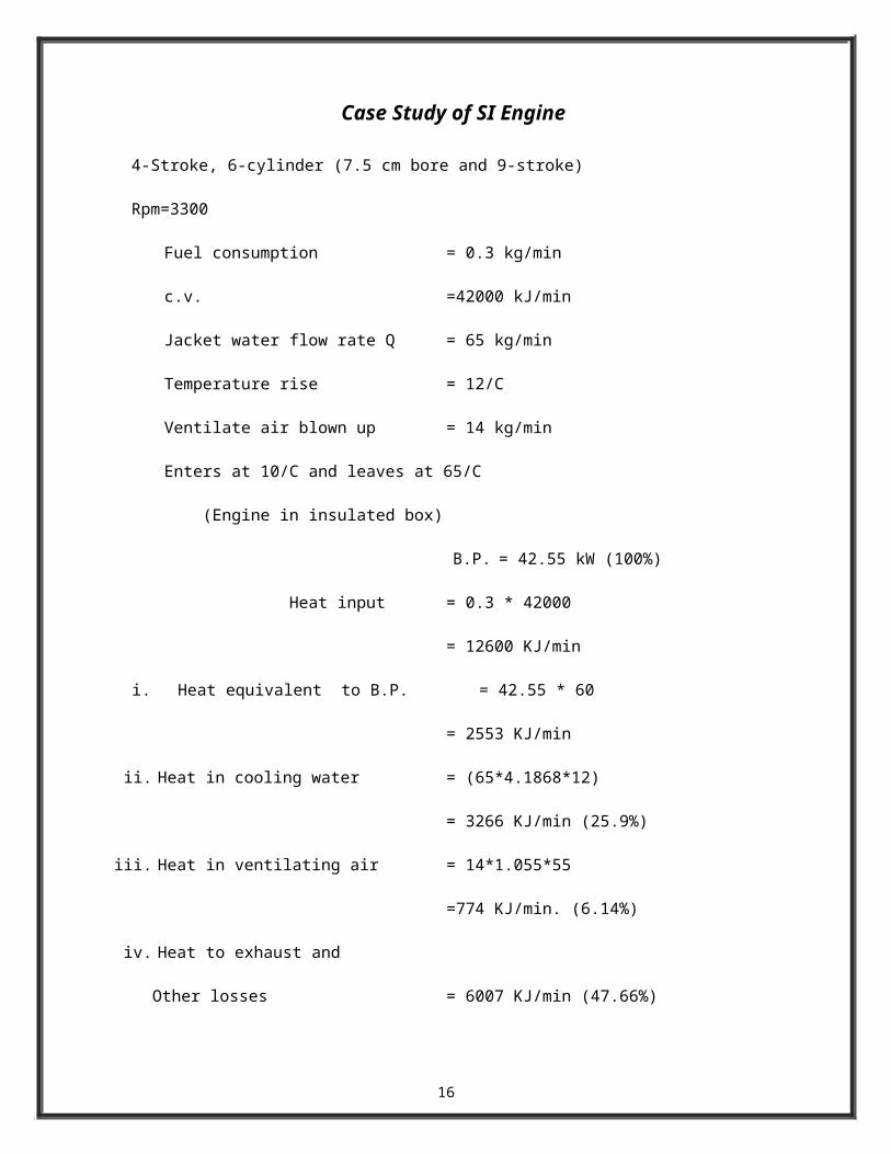
Case Study of SI Engine
4-Stroke, 6-cylinder (7.5 cm bore and 9-stroke)
Rpm=3300
Fuel consumption = 0.3 kg/min
c.v. =42000 kJ/min
Jacket water flow rate Q = 65 kg/min
Temperature rise = 12/C
Ventilate air blown up = 14 kg/min
Enters at 10/C and leaves at 65/C
(Engine in insulated box)
B.P. = 42.55 kW (100%)
Heat input = 0.3 * 42000
= 12600 KJ/min
i. Heat equivalent to B.P. = 42.55 * 60
= 2553 KJ/min
ii. Heat in cooling water = (65*4.1868*12)
= 3266 KJ/min (25.9%)
iii. Heat in ventilating air = 14*1.055*55
=774 KJ/min. (6.14%)
iv. Heat to exhaust and
Other losses = 6007 KJ/min (47.66%)
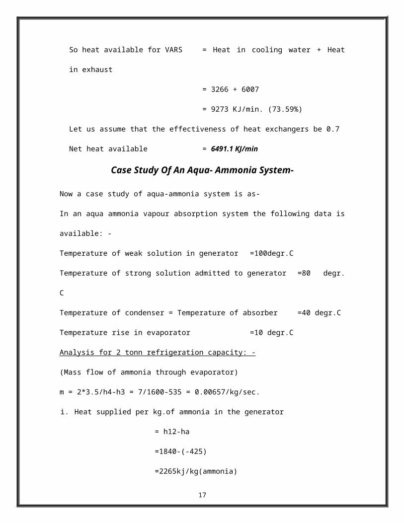
So heat available for VARS = Heat in cooling water + Heat in exhaust
= 3266 + 6007
= 9273 KJ/min. (73.59%)
Let us assume that the effectiveness of heat exchangers be 0.7
Net heat available = 6491.1 KJ/min
10
Case Study Of An Aqua- Ammonia System-
Now a case study of aqua-ammonia system is as-
In an aqua ammonia vapour absorption system the following data is available: -
Temperature of weak solution in generator =100degr.C
Temperature of strong solution admitted to generator =80 degr. C
Temperature of condenser = Temperature of absorber =40 degr.C
Temperature rise in evaporator =10 degr.C
Analysis for 2 tonn refrigeration capacity: -
(Mass flow of ammonia through evaporator)
m = 2*3.5/h4-h3 = 7/1600-535 = 0.00657/kg/sec.
i. Heat supplied per kg.of ammonia in the generator
= h12-ha
=1840-(-425)
=2265kj/kg(ammonia)
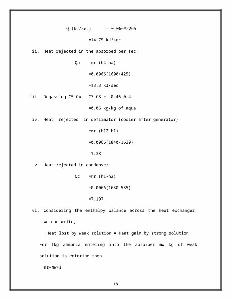
Q (kJ/sec) = 0.066*2265
=14.75 kJ/sec
ii. Heat rejected in the absorbed per sec.
Qa =mr (h4-ha)
=0.0066(1600+425)
=13.3 kJ/sec
iii. Degassing C5-Cw C7-C8 = 0.46-0.4
=0.06 kg/kg of aqua
iv. Heat rejected in deflimator (cooler after generator)
=mr (h12-h1)
=0.0066(1840-1630)
=1.38
11
v. Heat rejected in condenser
Qc =mr (h1-h2)
=0.0066(1630-535)
=7.197
vi. Considering the enthalpy balance across the heat exchanger, we can write,
Heat lost by weak solution = Heat gain by strong solution
For 1kg ammonia entering into the absorber mw kg of weak solution is entering then
ms=mw+1
mw (h8-h9) =(mw+1)(h7-h6);
mw (350-120) = (mw+1)(260-70)
40 mw = 190
mw = 4.75 kg/kg of ammonia
ms (strong solution handled by the pump)= mw+1
=4.75+1
=5.75 kg/kg of ammonia
=0.0066 * 5.75
=0.037 kg/sec
vii. c.o.p. Qe/Qg = h4-h3/Q9=1600-535/2265=0.47
viii. Energetic ne is given by
Ne = Qe/Qg [Tg/Te (Te-Te/Tq-Te)]
=0.47(100+273/10+273)(40-10/100-40)
=31%
Heat supplied =4.75kj/sec.
Heat rejected in absorber =3.3kj/sec.
Heat rejected =7.197
Heat rejected in deflimator =1.38
Heat supplied =14.75kj/sec.
12
Heat rejected =13.3+7.197
Heat rejected in condenser =7.197
Heat rejected in deflimator =1.38
Heat supplied =14.75kj/sec.
Heat rejected =13.3+7.197
=20.49kj/sec
Heat supplied =885kj/min
Heat rejected =1229.82kj/min
Heat available =3266+6007
Considering effectiveness =0.7=2286+4204
=6490kj/min
Heat required =885kj/min.
Thus we see that a large amount of heat is available and our requirement is lesser. The
system here described is simple basic. It can be further improved and made sophisticated by using
various control systems and relays. A basic control system is shown in fig. 7
Apart from the new design of vehicles installing (VARS), the existing vehicles can also
be equipped with this system and by studying the make of particular a proper placed can be found
out for erecting the system and tracing various circuits.
13
8.CONTROLLING THE SYSTEM
The exhaust coolant circuit is controlled by 3 valves V1, V2 and V3. The valve V1
operates the exhaust circuit and the valves V2 &V3 operate the coolant circuit where valve V3 is
two way valves and other two V1 and V2 are three way valves. The combination of position of
valve for different conditions are as shown below: -
V1 V2 V3
A/C OFF A/C OFF 1 1 1
A/C ON Summer 2 2 2
A/C ON Winter 3 3 1
14
9.ERECTION
By studying the manual of the particular vehicle, an appropriate place can be found out for the
erection of the system for existing vehicles and for newer design, it is to be already taken into
consideration. The condenser, expander, absorber and evaporator should be kept away from the
engine as possible because the engine evolves at high temp. The conditioned air supply and
distribution system remains the same as in the existing A/C vehicles.
10. ADVANTAGES OF VARS OVER VCRS
1) No moving parts so, quiet in operation, subjected to little wear, low maintenance cost. The
pump required quite small power in comparison with compressor.
2) Large capacity.
3) Excellent part load efficiency and almost constant c.o.p. of the system over a wide range of
load.
4) Automatic capacity control is easy.
5) Smaller space per unit capacity.
6) No harm to the ozone layer.
7) Inexpensive refrigerant.
8) Leakage can be easily detected in case of aqua ammonia system.
9) It can reduce the global warming of atmosphere.
15
11.CONCLUSION
Thus we have seen that the VARS is efficient in every respect, and can be
successfully implemented with better designs and sophistication. Now it is the task of the up
coming engineers to overcome the hurdles in the way if any and make our country’s people enjoy
the comfort and luxury of A/C and fuel will also be saved to a greater extent which would have
been consumed in excess by the (VARS) air conditioner.
16
12. REFERENCES
Basic Refrigeration and Air conditioning- P.N. Anathnarayan
Refrigeration and air conditioning – C.P. Arora
A course in Refrigeration and Air-conditioning- S.C.Arora, S.Domkundwar
Thermodynamics and Heat Engines- R.Yadav
A course in Internal Combustion Engines – M.L. Mathur, R.P. Sharma
Automobile Engineering –R.B. Gupta
A Text Book of Refrigeration And Air Conditioning –R.S. Khurmi & S.K. Gupta
WWW.Beyond2000.com (concept)
17
18