Embed Size (px)
Citation preview
Page | i
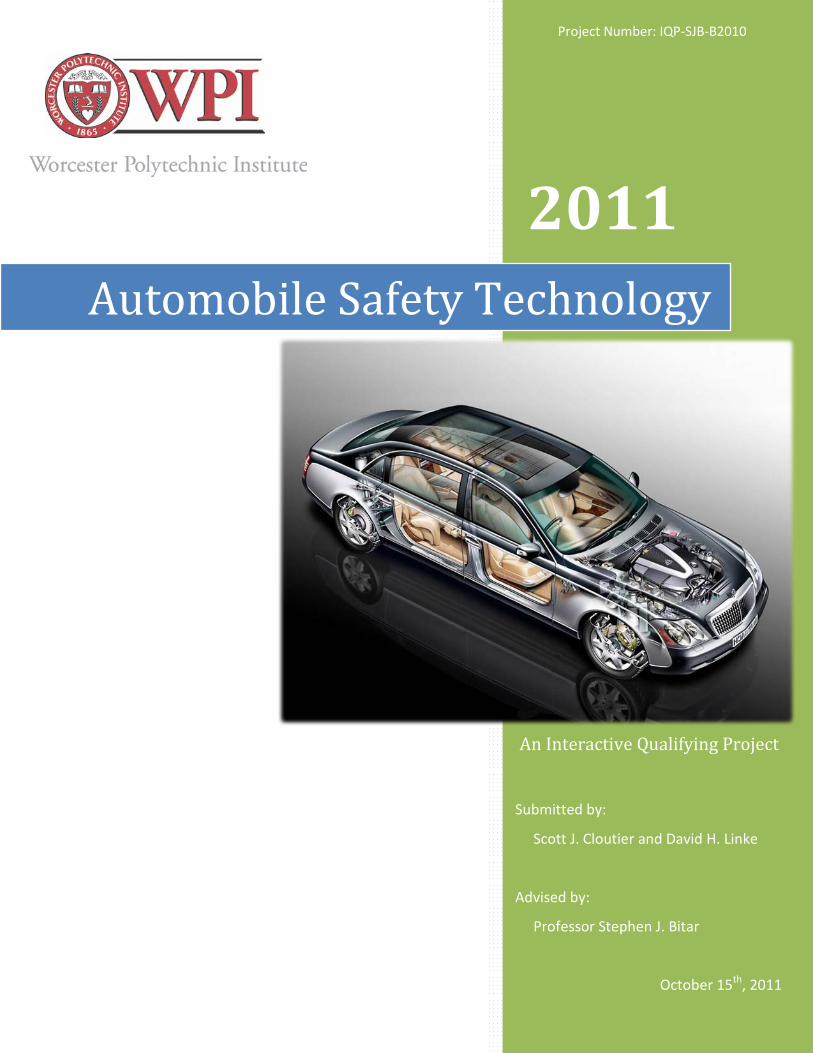
2011
Submitted by:
Scott J. Cloutier and David H. Linke
Advised by:
Professor Stephen J. Bitar
October 15th, 2011
Automobile Safety Technology
An Interactive Qualifying Project
Project Number: IQP-SJB-B2010

Page | ii
Abstract The purpose of this project was to evaluate the educational level of the WPI community
on automobile safety devices and develop an interactive medium through which visitors can
establish a better understanding of the technology. An interactive video presentation and
museum exhibit were constructed together to educate the community on the criteria of
history, purpose, and functionality for several major automotive technologies. The presentation
component incorporated pictures, videos, and diagrams to portray the educational material
about each technology, while the actual exhibit includes physical components from each
category to aide in visualization of these devices. This project produced positive feedback from
various members of the community as well as several recommendations for future renditions of
this project.
Page | iii
Acknowledgements Listed below are the individuals and organizations we would like to acknowledge for their contributions to our project:
Peter Cloutier Jr.
We’d like to thank Mr. Cloutier for his support in fabricating the structure for the exhibit.
Standard Auto Used Parts
The team extends a thank you to Standard Auto Used Parts for donations to this project, including the caliper brake assembly and the automobile bumper.
Sam’s Pull-A-Part Junkyard
We’d like to extend our gratitude and recognize Sam’s Pull-A-Part for providing support through discounted automobile parts
Page | iv
Authorship This project was developed for two student group members, both whom made mutual
contributions to the project. The responsibilities of each student were divided equally with respect to
each member’s skill set.
I. Cloutier was primarily responsible for the design and development of the display unit
structure. This responsibility also included the assembly and programming of the computer interface
system. He was also responsible for the creation of the scripts for each safety device branch.
Linke was primarily responsible for the creation and programming of the software presentation.
This responsibility included all five branches of the safety devices, as well as the introductory loop and
the about page. He was also responsible for the creation of the onboard display graphics and the
acquiring of the various safety devices.
Group responsibility was assigned over the arrangement and attachment of all safety devices to
the display unit. All group members will be responsible for contributions to the final project report
within their respected areas. The research and collection of content for the presentations were also a
mutual responsibility amongst all group members.

Page | v
Table of Contents Abstract ......................................................................................................................................................... ii
Acknowledgements ...................................................................................................................................... iii
Authorship ................................................................................................................................................... iv
Table of Contents .......................................................................................................................................... v
List of Figures ............................................................................................................................................. viii
List of Tables ................................................................................................................................................. x
Executive Summary ...................................................................................................................................... xi
Project Concept ........................................................................................................................................ xi
The Presentation ...................................................................................................................................... xi
The Seatbelt System ............................................................................................................................. xi
The Airbag System ............................................................................................................................... xi
The Anti-Lock Braking System .............................................................................................................. xi
Headlights, Turn Signals, & Crumple Zones ........................................................................................ xii
Electronic Traction & Stability Control ................................................................................................ xii
The Display Platform ...............................................................................................................................xiii
The Design ...........................................................................................................................................xiii
Functionality .......................................................................................................................................xiii
Project Results ........................................................................................................................................ xiv
Results & Analysis ............................................................................................................................... xiv
Community Feedback ......................................................................................................................... xiv
Chapter 1: Introduction ................................................................................................................................ 1
1.1 Primary Objectives .............................................................................................................................. 1
Chapter 2: Background ................................................................................................................................. 2
2.1 Initial Research Overview ................................................................................................................... 2
2.2 Survey Results ..................................................................................................................................... 3
2.3 Safety Devices ..................................................................................................................................... 6
2.3.1 Seatbelt System............................................................................................................................ 6
Seatbelt History – The First Belt ........................................................................................................ 6
Seatbelts – How do they work? ........................................................................................................ 6
The Safety-Restraint System ............................................................................................................. 6
2.3.2 Airbag System .............................................................................................................................. 7
Page | vi
The History of Airbags ....................................................................................................................... 7
Airbags – How do they work? ........................................................................................................... 7
The Safety-Restraint System ............................................................................................................. 7
2.3.3 Braking System ............................................................................................................................. 8
The Problem – Braking Without ABS ................................................................................................ 8
The History of ABS ............................................................................................................................. 8
How it Works – Modern ABS............................................................................................................. 8
2.3.4 Headlights, Signals & Crumple Zones......................................................................................... 10
Headlights ....................................................................................................................................... 10
Signals ............................................................................................................................................. 11
Crumple Zones ................................................................................................................................ 11
2.3.5 Electronic Traction & Stability Control Systems ........................................................................ 13
The Traction Control System ........................................................................................................... 13
The Stability Control System ........................................................................................................... 13
2.4 Summary ........................................................................................................................................... 15
Chapter 3: Methodology ............................................................................................................................. 16
3.1 Project Concept Design ..................................................................................................................... 16
3.1.1 Location and Venue ................................................................................................................... 16
3.1.2 Project Requirements ................................................................................................................ 17
Implicit Requirements ..................................................................................................................... 17
Explicit Requirements ..................................................................................................................... 17
3.1.3 Artist’s Rendition........................................................................................................................ 18
3.2 Presentation Component .................................................................................................................. 20
3.2.1 Presentation Criteria .................................................................................................................. 20
3.2.2 Program Flow Chart ................................................................................................................... 21
3.2.3 Presentation Interface ............................................................................................................... 23
3.2.4 Software Development .............................................................................................................. 24
3.2.5 Script Programming ................................................................................................................... 25
3.3 Hardware Component ...................................................................................................................... 26
3.3.1 Computer Interface .................................................................................................................... 27
3.3.2 Display Board Design.................................................................................................................. 28
3.3.3 Display Exhibit Construction ...................................................................................................... 29
Page | vii
3.3.4 Display Aesthetics & Final Touches ............................................................................................ 31
3.3.5 Internal Electrical Wiring ............................................................................................................ 32
3.4 The Safety Devices ............................................................................................................................ 33
3.4.1 The Seatbelt ............................................................................................................................... 33
3.4.2 The Deployed Airbag .................................................................................................................. 34
3.4.3 Headlight, Turn Signal, & Bumper .............................................................................................. 35
3.4.4 Brake Rotor Assembly ................................................................................................................ 36
3.4.5 Engine Control Unit .................................................................................................................... 37
3.5 Summary ........................................................................................................................................... 38
Chapter 4: Results ....................................................................................................................................... 39
4.1 Statistical Analysis ............................................................................................................................. 39
4.1.1 The Results ................................................................................................................................. 39
4.1.2 Analysis ...................................................................................................................................... 40
4.1.3 Validity & Discrepancies ............................................................................................................. 40
4.2 Project Feedback ............................................................................................................................... 41
4.2.1 Feedback Survey ........................................................................................................................ 41
4.3 Future Possibilities & Improvements ................................................................................................ 42
Chapter 5: Conclusion ................................................................................................................................. 43
Appendix A: Automobile Safety Survey ...................................................................................................... 45
Appendix B: Presentation Action Script Code ............................................................................................. 47
Page | viii
List of Figures Figure 1 – 3-Dimential Artist Rendition ....................................................................................................... xi
Figure 2 – 2-Dimential Diagram ................................................................................................................... xi
Figure 3 – Typical Seatbelt ........................................................................................................................... xi
Figure 4 – Airbag Crash Testing .................................................................................................................... xi
Figure 5 – Brake Pedal.................................................................................................................................. xi
Figure 6 – Crumple Zone Testing ................................................................................................................ xii
Figure 7 – Electronic Traction Control Testing ............................................................................................ xii
Figure 8 – Two-Dimensional Exhibit Mockup ............................................................................................. 18
Figure 9 – Three-Dimensional Exhibit Mockup ........................................................................................... 19
Figure 10 – Initial Program Flow Chart – Rev 1.0 ........................................................................................ 21
Figure 11 – Updated Program Flow Chart – Rev 2.0 ................................................................................... 22
Figure 12 – Presentation Interface Illustration ........................................................................................... 23
Figure 13 – Program Interface Flow Chart .................................................................................................. 24
Figure 14 – Hardware Component Layout Diagram ................................................................................... 26
Figure 15 – Block Diagram of Computer Interface ..................................................................................... 27
Figure 16 – Display Board Artistic Rendition .............................................................................................. 28
Figure 17 – Display Skeleton: Front ............................................................................................................ 29
Figure 18 – Display Skeleton: Side .............................................................................................................. 29
Figure 19 – Display Constructed: Front....................................................................................................... 30
Figure 20 – Display Constructed: Rear ........................................................................................................ 30
Figure 21 – Painted Trim & Title ................................................................................................................. 31
Figure 22 – Monitor & Speakers Installed .................................................................................................. 31
Figure 23 – Primary Power Switch .............................................................................................................. 32
Figure 24 – Dual-Receptacle Box ................................................................................................................ 32
Figure 25 – Laptop Computer & Speaker System ....................................................................................... 32
Figure 26 – Seatbelt Mechanism................................................................................................................. 33
Figure 27 – Deployed Airbag Unit ............................................................................................................... 34
Figure 28 – Headlight & Turn Signal Assembly ........................................................................................... 35
Figure 29 – Bumper Cut-Away (Crumple Zone) .......................................................................................... 35
Figure 30 – Bumper Shock Absorber .......................................................................................................... 35
Figure 31 – Brake Rotor Assembly .............................................................................................................. 36
Page | ix
Figure 32 – Open Engine Control Unit (ECU) .............................................................................................. 37
Figure 33 – Completed Automobile Safety Technology Display Exhibit ..................................................... 38
Figure 34 – Exhibit Results: Number of Hits per Device ............................................................................. 39
Page | x
List of Tables Table 1 – Identifying Safety Devices ............................................................................................................. 3 Table 2 – Safety Device Importance ............................................................................................................. 4
Page | xi
Executive Summary One of the most sophisticated technological advances on our planet has become a crucial part of
everyday human life. The progression and development of the automobile has led to an increase in the
dangers related to its operation. Today’s modern vehicles are equipped with many devices that help
prevent serious injury in the event of a crash, or help avoid an accident all together. Most average
drivers may recognize the names of some common safety devices in their vehicle, but many lack the
knowledge of how these devices effectively work in providing them with a safe driving experience each
day.
The Objective: The primary objective of this project is to educate the public on the history, purpose, and
technology of common safety devices of modern automobiles.
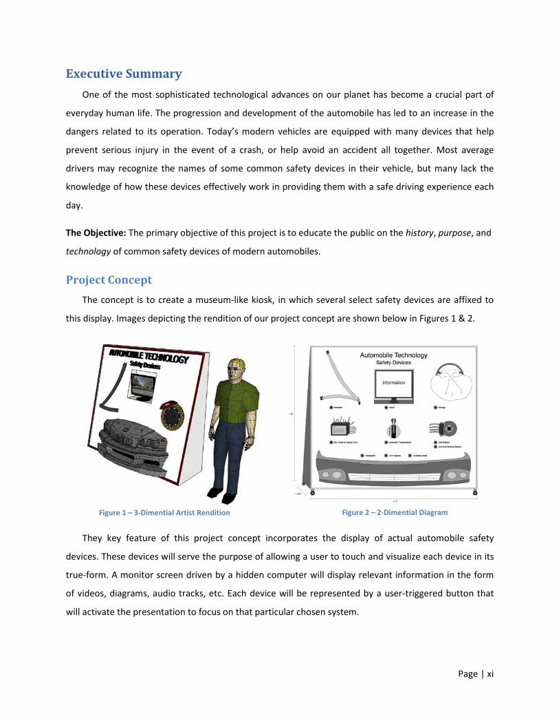
Project Concept The concept is to create a museum-like kiosk, in which several select safety devices are affixed to
this display. Images depicting the rendition of our project concept are shown below in Figures 1 & 2.
Figure 1 – 3-Dimential Artist Rendition Figure 2 – 2-Dimential Diagram
They key feature of this project concept incorporates the display of actual automobile safety
devices. These devices will serve the purpose of allowing a user to touch and visualize each device in its
true-form. A monitor screen driven by a hidden computer will display relevant information in the form
of videos, diagrams, audio tracks, etc. Each device will be represented by a user-triggered button that
will activate the presentation to focus on that particular chosen system.
Page | xi
The Presentation For the educational presentation, several safety devices were chosen to educate the community on
their History, Purpose, and Functionality in modern automobiles.
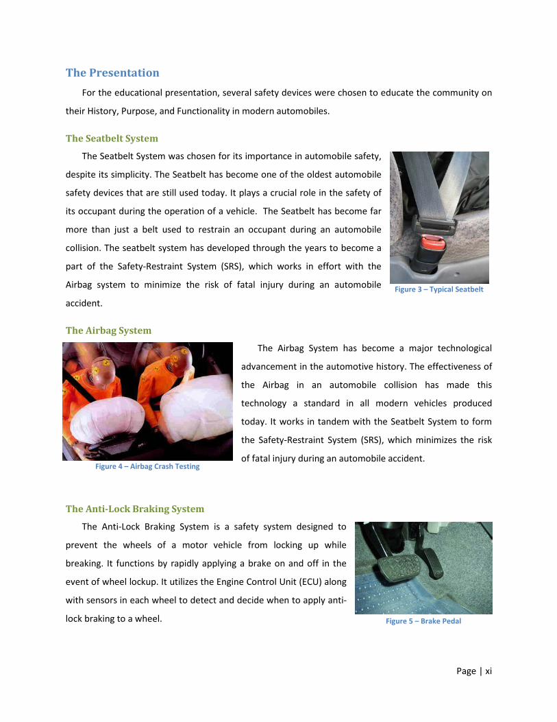
The Seatbelt System
The Seatbelt System was chosen for its importance in automobile safety,
despite its simplicity. The Seatbelt has become one of the oldest automobile
safety devices that are still used today. It plays a crucial role in the safety of
its occupant during the operation of a vehicle. The Seatbelt has become far
more than just a belt used to restrain an occupant during an automobile
collision. The seatbelt system has developed through the years to become a
part of the Safety-Restraint System (SRS), which works in effort with the
Airbag system to minimize the risk of fatal injury during an automobile
accident.
The Airbag System
The Airbag System has become a major technological
advancement in the automotive history. The effectiveness of
the Airbag in an automobile collision has made this
technology a standard in all modern vehicles produced
today. It works in tandem with the Seatbelt System to form
the Safety-Restraint System (SRS), which minimizes the risk
of fatal injury during an automobile accident.
The Anti-Lock Braking System
The Anti-Lock Braking System is a safety system designed to
prevent the wheels of a motor vehicle from locking up while
breaking. It functions by rapidly applying a brake on and off in the
event of wheel lockup. It utilizes the Engine Control Unit (ECU) along
with sensors in each wheel to detect and decide when to apply anti-
lock braking to a wheel.
Figure 3 – Typical Seatbelt
Figure 4 – Airbag Crash Testing
Figure 5 – Brake Pedal

Page | xii
Headlights, Turn Signals, & Crumple Zones
Headlights function to illuminate the road in front of an
automobile when visibility is limited. They are a crucial component
to the safe operation of automobiles when visibility is limited.
Advancements in headlight technology have led to adaptive
headlights, which adjust the angle of the beams to upcoming curves
on a road. Turn signals function to alert other automobiles of an
upcoming change in direction of your automobile. They are
essentially headlights that flash when activated until a turn
completion is detected. Crumple Zones function to redistribute
energy from a collision away from occupants. They were a
significant development in preventing serious injury to occupants
during a collision by collapsing, crumpling, deforming, and crushing
on impact.
Electronic Traction & Stability Control
The Electronic Traction Control System functions to keep automobile wheels from losing traction
when accelerating. It is the Anti-Lock Braking System applied to acceleration rather than braking. It is
controlled by the ECU and shares sensors and
control mechanisms with the ABS. The Stability
Control System functions to ensure an
automobile stays on its intended path through
turns. It utilizes the Anti-Lock Braking System to
prevent skidding during turns as well as
potential rollovers. Both of these systems are
modern automobile safety achievements that
have significantly reduced automobile collisions.
Figure 6 – Crumple Zone Testing
Figure 7 – Electronic Traction Control Testing
Page | xiii
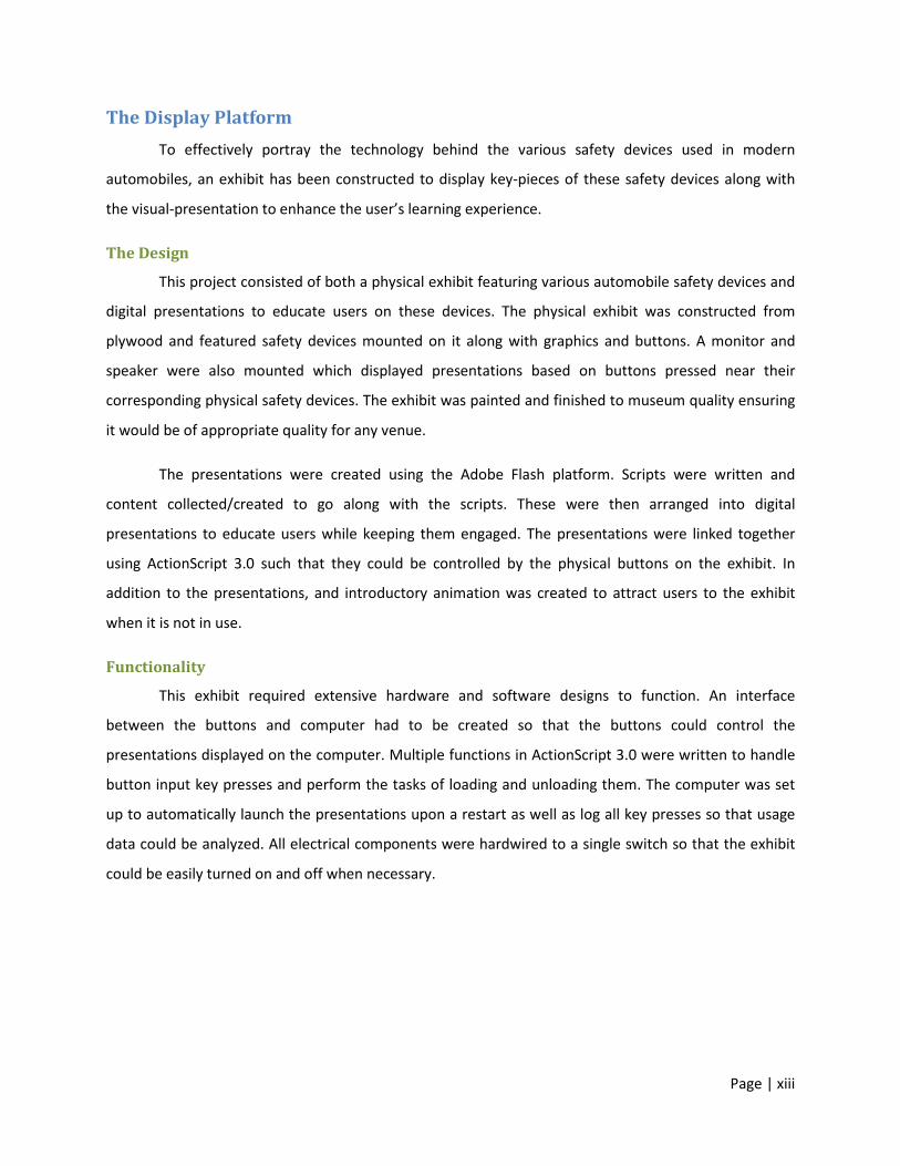
The Display Platform To effectively portray the technology behind the various safety devices used in modern
automobiles, an exhibit has been constructed to display key-pieces of these safety devices along with
the visual-presentation to enhance the user’s learning experience.
The Design
This project consisted of both a physical exhibit featuring various automobile safety devices and
digital presentations to educate users on these devices. The physical exhibit was constructed from
plywood and featured safety devices mounted on it along with graphics and buttons. A monitor and
speaker were also mounted which displayed presentations based on buttons pressed near their
corresponding physical safety devices. The exhibit was painted and finished to museum quality ensuring
it would be of appropriate quality for any venue.
The presentations were created using the Adobe Flash platform. Scripts were written and
content collected/created to go along with the scripts. These were then arranged into digital
presentations to educate users while keeping them engaged. The presentations were linked together
using ActionScript 3.0 such that they could be controlled by the physical buttons on the exhibit. In
addition to the presentations, and introductory animation was created to attract users to the exhibit
when it is not in use.
Functionality
This exhibit required extensive hardware and software designs to function. An interface
between the buttons and computer had to be created so that the buttons could control the
presentations displayed on the computer. Multiple functions in ActionScript 3.0 were written to handle
button input key presses and perform the tasks of loading and unloading them. The computer was set
up to automatically launch the presentations upon a restart as well as log all key presses so that usage
data could be analyzed. All electrical components were hardwired to a single switch so that the exhibit
could be easily turned on and off when necessary.
Page | xiv
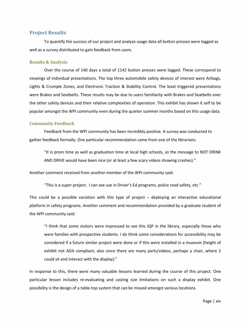
Project Results To quantify the success of our project and analyze usage data all button presses were logged as
well as a survey distributed to gain feedback from users.
Results & Analysis
Over the course of 140 days a total of 1142 button presses were logged. These correspond to
viewings of individual presentations. The top three automobile safety devices of interest were Airbags,
Lights & Crumple Zones, and Electronic Traction & Stability Control. The least triggered presentations
were Brakes and Seatbelts. These results may be due to users familiarity with Brakes and Seatbelts over
the other safety devices and their relative complexities of operation. This exhibit has shown it self to be
popular amongst the WPI community even during the quieter summer months based on this usage data.
Community Feedback
Feedback from the WPI community has been incredibly positive. A survey was conducted to
gather feedback formally. One particular recommendation came from one of the librarians:
“It is prom time as well as graduation time at local high schools, so the message to NOT DRINK
AND DRIVE would have been nice (or at least a few scary videos showing crashes).”
Another comment received from another member of the WPI community said:
“This is a super project. I can see use in Driver’s Ed programs, police road safety, etc.”
This could be a possible variation with this type of project – deploying an interactive educational
platform in safety programs. Another comment and recommendation provided by a graduate student of
the WPI community said:
“I think that some visitors were impressed to see this IQP in the library, especially those who
were families with prospective students. I do think some considerations for accessibility may be
considered if a future similar project were done or if this were installed in a museum (height of
exhibit not ADA compliant, also since there are many parts/videos, perhaps a chair, where 2
could sit and interact with the display).”
In response to this, there were many valuable lessons learned during the course of this project. One
particular lesson includes re-evaluating and casting size limitations on such a display exhibit. One
possibility is the design of a table-top system that can be moved amongst various locations.
Page | 1
Chapter 1: Introduction One of the most sophisticated technological advances on our planet has become a crucial part
of everyday human life. The progression and development of the automobile has led to an increase in
the dangers related to its operation. Today’s modern vehicles are equipped with many devices that help
prevent serious injury in the event of a crash, or help avoid an accident all together. Most average
drivers may recognize the names of some common safety devices in their vehicle, but many lack the
knowledge of how these devices effectively work in providing them with a safe driving experience each
day.
1.1 Primary Objectives Based on the problem statement described above, a list of objectives has been determined to
outline this project and provide a viable solution to the problem.
• Identify several significant automobile safety devices and the technology involved.
• Illustrate how each device works and distinguish the purpose of those devices.
• To provide a medium in which the user can touch and see these devices safely.
Today’s technology has brought upon numerous types of safety devices in today’s modern
automobiles. These devices can range from the traditional safety belt invention – better known as the
Seatbelt, to more sophisticated systems such as Electronic Stability Control that can help the driver
maintain control of the vehicle and prevent serious injury. While many of these technologies have been
incorporated into the modern automobile that we drive today, many drivers and passengers of these
vehicles have little to no understanding of how some of these devices function properly. There are some
devices found on all modern automobiles that some people may not even consider a “safety” device,
when in-fact they play an important role in automobile safety.
The goal of this Interactive Qualifying Project (IQP) is to briefly assess the general automobile
knowledge of a certain community and use these results to construct a medium by which to educate this
community on several select safety devices.
Page | 2
Chapter 2: Background This section will cover the all research that was conducted for this project. This includes
research driven by the defined problem statement, community distributed survey results, and the
educational information pertaining to various safety devices.
2.1 Initial Research Overview The initial development phase was advanced by conducting research on information pertaining
to the determined problem statement and primary objective. A list was compiled of all the automobile
safety devices and technologies that are present on modern automobile systems. The technologies in
this list were sorted into three categories: active safety systems, passive safety systems, and safety
luxuries. Each of the technologies was accompanied by a description of their function as well as relevant
links with more information on them. Once this list was constructed we needed to decide upon which
technologies we would research further. To do this, a campus-wide survey was distributed to evaluate
the educational level of the community to determine which safety devices pertain to the problem
statement.
After the results from the survey were collected and analyzed, several safety devices were
chosen as the primary devices to gather information about to use as a means to educate the community
and solve the problem defined in this project. The goal was to define in an educational manner the
purpose and functionality of each safety device in modern automobiles. It can be assumed that the
majority of automobile drivers today are aware of what some of the safety devices are, but may not
know exactly how they function to play the important role in their safety. It’s important that all
automobile drivers should have a thorough understanding of the various devices they work with every
day. Some drivers may even assume that having an airbag system in their automobile means they can go
without wearing their seatbelt. This thought process could prove to be dangerous, and is one reason
why this knowledge and understanding of these safety devices must be rectified in an educational
manner.
Page | 3
2.2 Survey Results To understand how the community is affected by our problem statement, a short survey was
created to gather an understanding of the current educational level of modern automobile safety
devices. This survey addressed several questions pertaining to the identification of crucial safety devices
on modern automobiles and rating the importance of each device on its role in making an automobile
safe. The results of the survey were compiled below with respect to a few questions of interest.
For one of the primary questions, the survey asked:
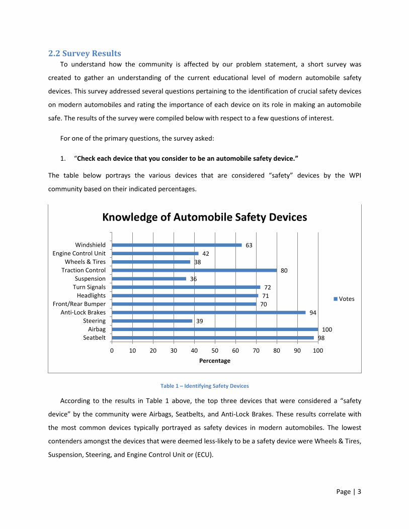
1. “Check each device that you consider to be an automobile safety device.”
The table below portrays the various devices that are considered “safety” devices by the WPI
community based on their indicated percentages.
Table 1 – Identifying Safety Devices
According to the results in Table 1 above, the top three devices that were considered a “safety
device” by the community were Airbags, Seatbelts, and Anti-Lock Brakes. These results correlate with
the most common devices typically portrayed as safety devices in modern automobiles. The lowest
contenders amongst the devices that were deemed less-likely to be a safety device were Wheels & Tires,
Suspension, Steering, and Engine Control Unit or (ECU).
98 100
39 94
70 71 72
36 80
38 42
63
SeatbeltAirbag
SteeringAnti-Lock Brakes
Front/Rear BumperHeadlights
Turn SignalsSuspension
Traction ControlWheels & Tires
Engine Control UnitWindshield
0 10 20 30 40 50 60 70 80 90 100Percentage
Knowledge of Automobile Safety Devices
Votes
Page | 4
Another primary question of interest addressed the importance of each safety device on the list.
The question asked:
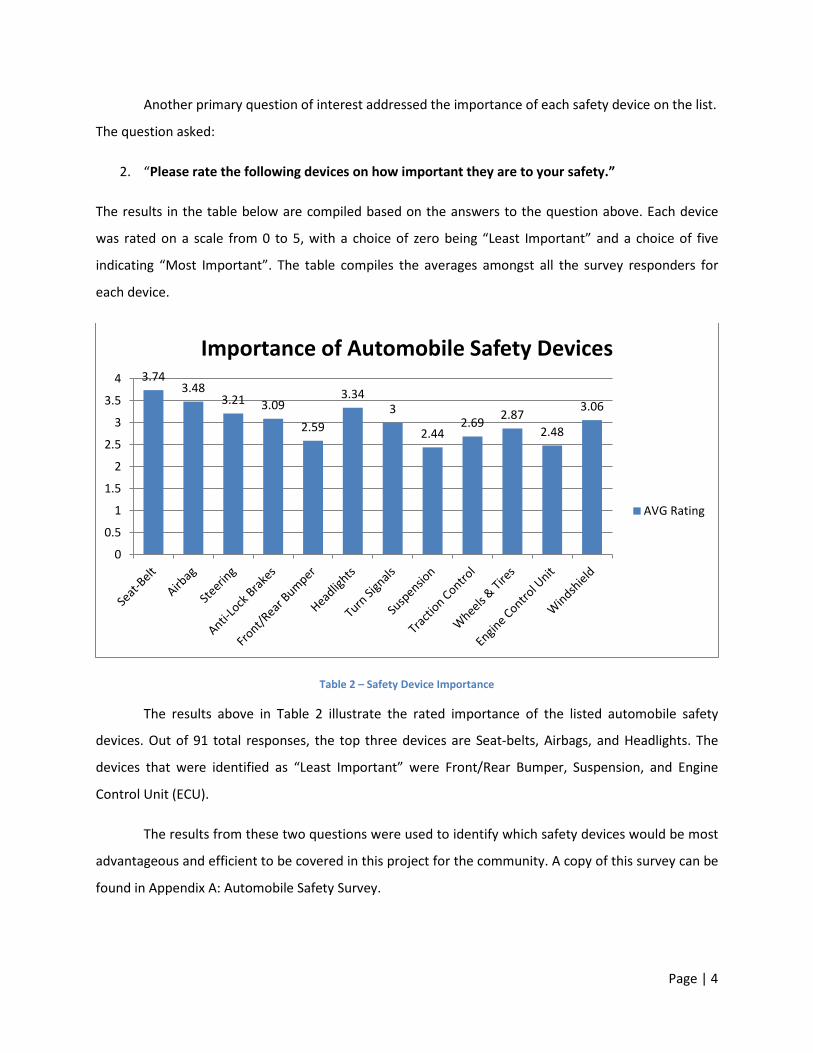
2. “Please rate the following devices on how important they are to your safety.”
The results in the table below are compiled based on the answers to the question above. Each device
was rated on a scale from 0 to 5, with a choice of zero being “Least Important” and a choice of five
indicating “Most Important”. The table compiles the averages amongst all the survey responders for
each device.
Table 2 – Safety Device Importance
The results above in Table 2 illustrate the rated importance of the listed automobile safety
devices. Out of 91 total responses, the top three devices are Seat-belts, Airbags, and Headlights. The
devices that were identified as “Least Important” were Front/Rear Bumper, Suspension, and Engine
Control Unit (ECU).
The results from these two questions were used to identify which safety devices would be most
advantageous and efficient to be covered in this project for the community. A copy of this survey can be
found in Appendix A: Automobile Safety Survey.
3.74 3.48
3.21 3.09
2.59
3.34 3
2.44 2.69 2.87
2.48
3.06
0
0.5
1
1.5
2
2.5
3
3.5
4
Importance of Automobile Safety Devices
AVG Rating
Page | 5
The following list of safety devices were chosen as areas in which the community may be least
knowledgeable about and therefore need a better understanding of their purpose and functionality to
develop a level of respect for these life-saving devices.
• Safety-Restraint System (SRS)
o Seatbelts
o Air Bags
• Anti-Lock Braking System (ABS)
o Anti-Lock Disc Brakes
• Passive Safety Systems
o Bumper Crumple Zones
o Headlights
o Turn Signals
• Engine Control Unit (ECU)
o Electronic Traction Control
o Electronic Stability Control
The Safety-Restraint System that is comprised of Seatbelts and Airbags are two of the most
heard-of automobile safety devices. While these two safety devices are standards in today’s modern
automobile technology, very few people understand how these two devices work hand-in-hand in
preventing serious injury. Along with the Safety-Restraint System, the Anti-Lock Braking System is
another key safety device in modern automobiles that many individuals may be familiar with but may
not understand their true functionality. These top three safety devices have been included for their
importance in automobile safety.
Aside from the top three most-heard of automobile safety devices, the Passive Safety System
category has been included for their important role in automobile safety as well. Comprised of
Headlights, Turn Signals, and Bumper Crumple Zones, these three features equipped on modern
automobiles serve a far greater purpose than most would assume.
To complete the list, two more recent safety systems that are purely part of the Engine Control
Unit play a crucial role in improving the drivability and increasing safety of the modern automobile. The
Electronic Traction Control & Stability Control Systems are just two safety systems that many drivers
may not even know that their vehicle has them equipped.
Page | 6
2.3 Safety Devices This section covers the research done on the history and functionality of each safety device that was
chosen to educate the community on.
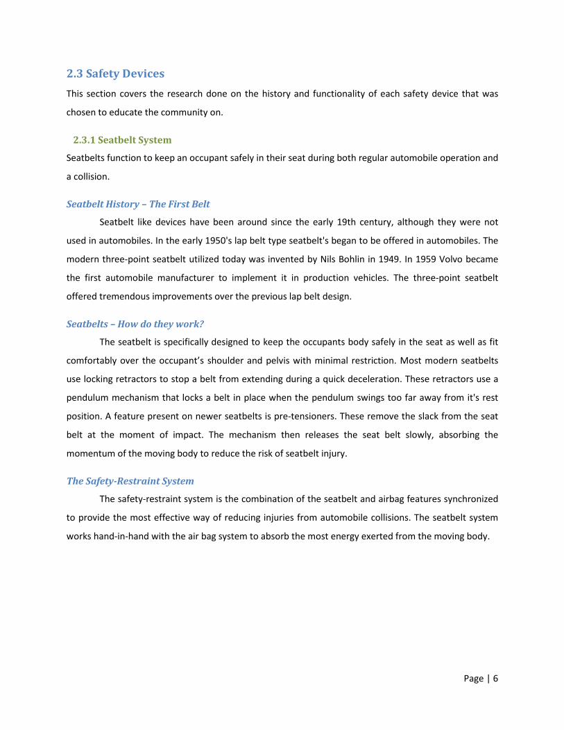
2.3.1 Seatbelt System
Seatbelts function to keep an occupant safely in their seat during both regular automobile operation and
a collision.
Seatbelt History – The First Belt
Seatbelt like devices have been around since the early 19th century, although they were not
used in automobiles. In the early 1950's lap belt type seatbelt's began to be offered in automobiles. The
modern three-point seatbelt utilized today was invented by Nils Bohlin in 1949. In 1959 Volvo became
the first automobile manufacturer to implement it in production vehicles. The three-point seatbelt
offered tremendous improvements over the previous lap belt design.
Seatbelts – How do they work?
The seatbelt is specifically designed to keep the occupants body safely in the seat as well as fit
comfortably over the occupant’s shoulder and pelvis with minimal restriction. Most modern seatbelts
use locking retractors to stop a belt from extending during a quick deceleration. These retractors use a
pendulum mechanism that locks a belt in place when the pendulum swings too far away from it's rest
position. A feature present on newer seatbelts is pre-tensioners. These remove the slack from the seat
belt at the moment of impact. The mechanism then releases the seat belt slowly, absorbing the
momentum of the moving body to reduce the risk of seatbelt injury.
The Safety-Restraint System
The safety-restraint system is the combination of the seatbelt and airbag features synchronized
to provide the most effective way of reducing injuries from automobile collisions. The seatbelt system
works hand-in-hand with the air bag system to absorb the most energy exerted from the moving body.
Page | 7
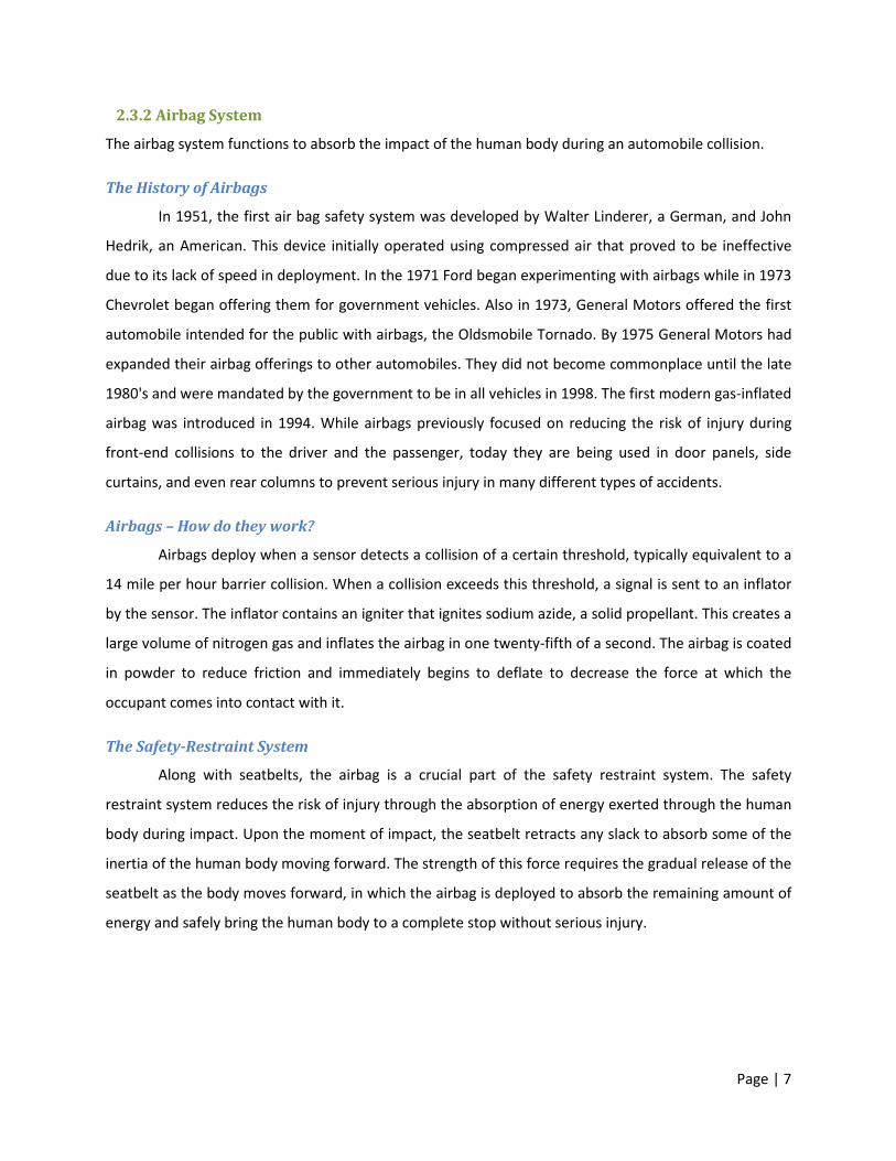
2.3.2 Airbag System
The airbag system functions to absorb the impact of the human body during an automobile collision.
The History of Airbags
In 1951, the first air bag safety system was developed by Walter Linderer, a German, and John
Hedrik, an American. This device initially operated using compressed air that proved to be ineffective
due to its lack of speed in deployment. In the 1971 Ford began experimenting with airbags while in 1973
Chevrolet began offering them for government vehicles. Also in 1973, General Motors offered the first
automobile intended for the public with airbags, the Oldsmobile Tornado. By 1975 General Motors had
expanded their airbag offerings to other automobiles. They did not become commonplace until the late
1980's and were mandated by the government to be in all vehicles in 1998. The first modern gas-inflated
airbag was introduced in 1994. While airbags previously focused on reducing the risk of injury during
front-end collisions to the driver and the passenger, today they are being used in door panels, side
curtains, and even rear columns to prevent serious injury in many different types of accidents.
Airbags – How do they work?
Airbags deploy when a sensor detects a collision of a certain threshold, typically equivalent to a
14 mile per hour barrier collision. When a collision exceeds this threshold, a signal is sent to an inflator
by the sensor. The inflator contains an igniter that ignites sodium azide, a solid propellant. This creates a
large volume of nitrogen gas and inflates the airbag in one twenty-fifth of a second. The airbag is coated
in powder to reduce friction and immediately begins to deflate to decrease the force at which the
occupant comes into contact with it.
The Safety-Restraint System
Along with seatbelts, the airbag is a crucial part of the safety restraint system. The safety
restraint system reduces the risk of injury through the absorption of energy exerted through the human
body during impact. Upon the moment of impact, the seatbelt retracts any slack to absorb some of the
inertia of the human body moving forward. The strength of this force requires the gradual release of the
seatbelt as the body moves forward, in which the airbag is deployed to absorb the remaining amount of
energy and safely bring the human body to a complete stop without serious injury.
Page | 8
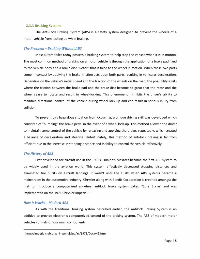
2.3.3 Braking System
The Anti-Lock Braking System (ABS) is a safety system designed to prevent the wheels of a
motor vehicle from locking up while braking.
The Problem – Braking Without ABS
Most automobiles today possess a braking system to help stop the vehicle when it is in motion.
The most common method of braking on a motor vehicle is through the application of a brake pad fixed
to the vehicle body and a brake disc “Rotor” that is fixed to the wheel in motion. When these two parts
come in contact by applying the brake, friction acts upon both parts resulting in vehicular deceleration.
Depending on the vehicle’s initial speed and the traction of the wheels on the road, the possibility exists
where the friction between the brake-pad and the brake disc become so great that the rotor and the
wheel cease to rotate and result in wheel-locking. This phenomenon inhibits the driver’s ability to
maintain directional control of the vehicle during wheel lock-up and can result in serious injury from
collision.
To prevent this hazardous situation from occurring, a unique driving skill was developed which
consisted of “pumping” the brake pedal in the event of a wheel lock-up. This method allowed the driver
to maintain some control of the vehicle by releasing and applying the brakes repeatedly, which created
a balance of deceleration and steering. Unfortunately, this method of anti-lock braking is far from
efficient due to the increase in stopping distance and inability to control the vehicle effectively.
The History of ABS
First developed for aircraft use in the 1950s, Dunlop’s Maxaret became the first ABS system to
be widely used in the aviation world. This system effectively decreased stopping distances and
eliminated tire bursts on aircraft landings. It wasn’t until the 1970s when ABS systems became a
mainstream in the automotive industry. Chrysler along with Bendix Corporation is credited amongst the
first to introduce a computerized all-wheel antilock brake system called “Sure Brake” and was
implemented on the 1971 Chrysler Imperial.1
How it Works – Modern ABS
As with the traditional braking system described earlier, the Antilock Braking System is an
additive to provide electronic-computerized control of the braking system. The ABS of modern motor
vehicles consists of four main components:
1 http://imperialclub.org/~imperialclub/Yr/1973/Data/49.htm
Page | 9
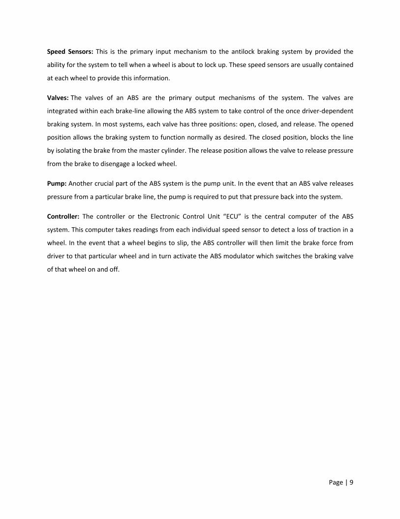
Speed Sensors: This is the primary input mechanism to the antilock braking system by provided the
ability for the system to tell when a wheel is about to lock up. These speed sensors are usually contained
at each wheel to provide this information.
Valves: The valves of an ABS are the primary output mechanisms of the system. The valves are
integrated within each brake-line allowing the ABS system to take control of the once driver-dependent
braking system. In most systems, each valve has three positions: open, closed, and release. The opened
position allows the braking system to function normally as desired. The closed position, blocks the line
by isolating the brake from the master cylinder. The release position allows the valve to release pressure
from the brake to disengage a locked wheel.
Pump: Another crucial part of the ABS system is the pump unit. In the event that an ABS valve releases
pressure from a particular brake line, the pump is required to put that pressure back into the system.
Controller: The controller or the Electronic Control Unit “ECU” is the central computer of the ABS
system. This computer takes readings from each individual speed sensor to detect a loss of traction in a
wheel. In the event that a wheel begins to slip, the ABS controller will then limit the brake force from
driver to that particular wheel and in turn activate the ABS modulator which switches the braking valve
of that wheel on and off.
Page | 10
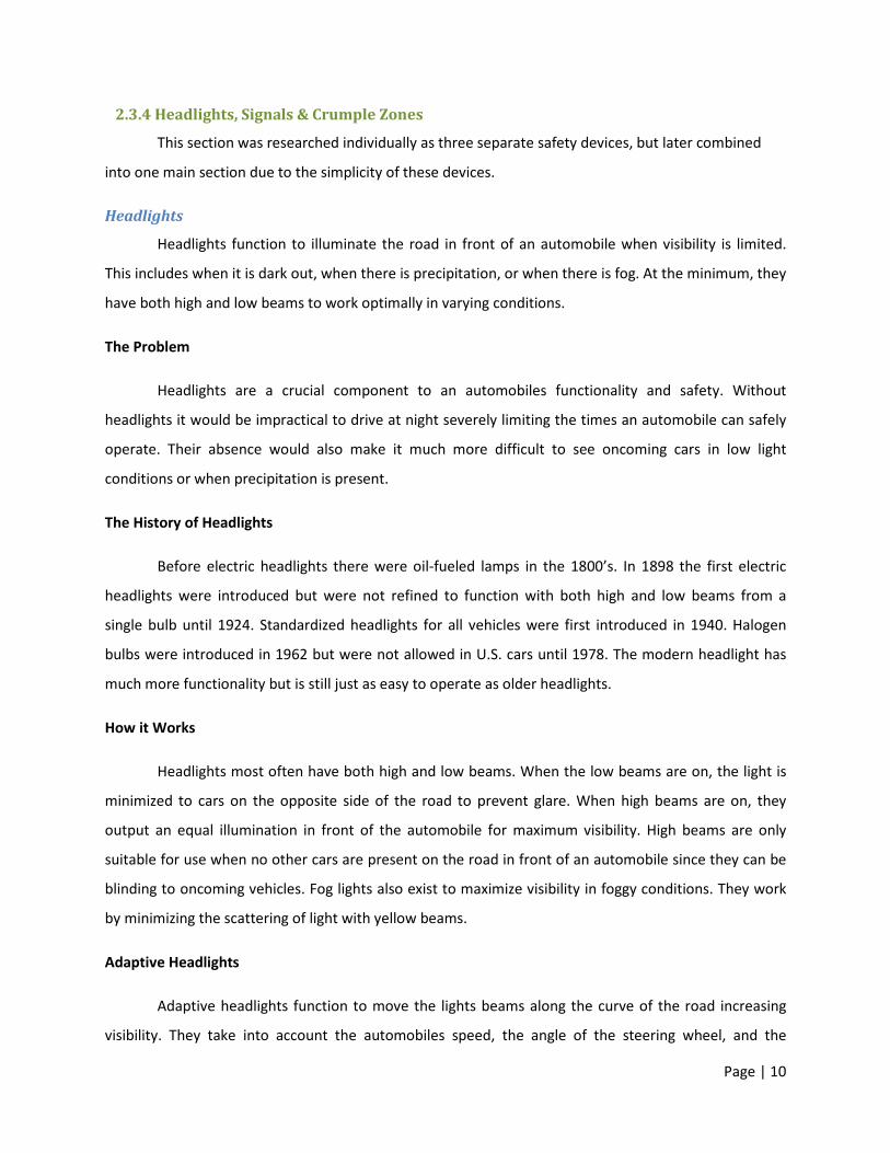
2.3.4 Headlights, Signals & Crumple Zones
This section was researched individually as three separate safety devices, but later combined
into one main section due to the simplicity of these devices.
Headlights
Headlights function to illuminate the road in front of an automobile when visibility is limited.
This includes when it is dark out, when there is precipitation, or when there is fog. At the minimum, they
have both high and low beams to work optimally in varying conditions.
The Problem
Headlights are a crucial component to an automobiles functionality and safety. Without
headlights it would be impractical to drive at night severely limiting the times an automobile can safely
operate. Their absence would also make it much more difficult to see oncoming cars in low light
conditions or when precipitation is present.
The History of Headlights
Before electric headlights there were oil-fueled lamps in the 1800’s. In 1898 the first electric
headlights were introduced but were not refined to function with both high and low beams from a
single bulb until 1924. Standardized headlights for all vehicles were first introduced in 1940. Halogen
bulbs were introduced in 1962 but were not allowed in U.S. cars until 1978. The modern headlight has
much more functionality but is still just as easy to operate as older headlights.
How it Works
Headlights most often have both high and low beams. When the low beams are on, the light is
minimized to cars on the opposite side of the road to prevent glare. When high beams are on, they
output an equal illumination in front of the automobile for maximum visibility. High beams are only
suitable for use when no other cars are present on the road in front of an automobile since they can be
blinding to oncoming vehicles. Fog lights also exist to maximize visibility in foggy conditions. They work
by minimizing the scattering of light with yellow beams.
Adaptive Headlights
Adaptive headlights function to move the lights beams along the curve of the road increasing
visibility. They take into account the automobiles speed, the angle of the steering wheel, and the
Page | 11
rotation of the car around its vertical axis to move the headlights using small electric motors. They
typically have a 30° range of motion to move the lights 15° to the left or right. Some cars even have
cornering lights that illuminate if the turn exceeds this range of motion.
Signals Turn signals function to alert other automobiles of an upcoming change in direction of your automobile.
The Problem
Communicating with other automobile drivers is crucial to staying safe on the road and avoiding
potential accidents. By properly using turn signal lights when changing a vehicles direction, other drivers
are informed of this change. Failure to use turn signals to indicate a lane change or turn could cause a
serious accident.
The History of Signals
Turn signals were first implemented in 1938 on Buick vehicles. There has been little innovation
in terms of their function since then other than improved auto-turn off mechanisms and lighting
advancements.
How it Works
With today’s technology, Signals function today in a similar method as to how Headlights
operate. They are turned on manually and turn off automatically when a sufficient change in the
direction of an automobile is detected. They feature a ticking noise that alerts a driver when they are
signaling. In addition to providing functionality in alerting other automobiles of turns, they also serve as
emergency flashers. Both signals can be used simultaneously to indicate an emergency during or after
an automobile accident or vehicle malfunction by simply pressing an emergency signal button.
Crumple Zones
When an automobile is in a collision, the resulting energy from the collision can cause harm to
the occupants. Crumple zones work by lessening this energy, redistributing it to other areas. These areas
are known as crumple zones, since they distort and crumple upon collision.
The Problem
When automobiles did not have crumple zones they were completely rigid structures. During a
collision much of the resulting energy would be directly transferred to the occupants causing them to be
Page | 12
propelled in the direction of the collision. This has the potential to cause significantly more harm than if
this energy were reduced. Crumple zones solve this problem by managing the energy, distributing it to
other areas of the automobile to lessen its effect on the passenger cabin.
The History of Crumple Zones
In the early days of automobiles, it was common belief that the more rigid and strong the
automobile structure, the less harm its occupants would suffer during a collision. One inventor who
worked for Daimler-Benz, Béla Barényi, went against this common practice. He realized that by
rearranging the components of an automobile, the energy from a collision could be minimized to the
passenger cabin. While his idea was patented in 1952, it wasn’t until 1959 that it was first implemented
in Mercedes-Benz 220 models.
How it Works
When an automobile is in a collision there can be a large amount of kinetic energy present that
has to be absorbed somewhere. Crumple zones work to absorb this energy as well as redistribute it to
areas other than the passenger cabin. This is accomplished by building components on the front and
rear of cars that collapse, crumple, deform, and crush on impact. By making these components take
much of the energy out of the collision, the car decelerates slower causing a less forceful impact. Once
an automobile is hit in a crumple zone, the frame of the automobile is designed to redistribute the
energy to other areas of the car to further reduce the impact for the occupants. Crumple zones are also
designed to increase the rigidity of the passenger cabin upon a collision. It is one of the primary passive
safety systems that exist in automobiles to ensure the occupants are as safe as possible during a
collision.
Page | 13
2.3.5 Electronic Traction & Stability Control Systems
All modern vehicles contain an ECU, or engine control unit, to ensure an internal combustion
engine runs properly and optimally. ECU’s are essentially computers with microprocessors, memory, a
CPU, and software. In addition to controlling the engine, many ECU’s contain additional functionality
such as cruise control, automatic transmission control, traction control, and stability control.
The Traction Control System
The traction control system functions to keep automobiles wheels from losing traction when
accelerating.
The Problem
When an automobile accelerates it may not grip the road due to a quick acceleration, slick road
conditions, or both. Traction control functions to correct the skidding and locking up of wheels that can
occur due to these factors.
How it Works
The traction control functions using the ECU to process information from sensors and route
power to wheels appropriately using values it calculates. It takes into account the pressure placed on
the accelerator and sensors on the wheels that indicate whether they are slipping or not. If slippage is
detected, less power is routed to the wheel and some braking pressure may be placed on it. By doing
this, it is essentially the opposite of the anti-lock braking system. The only difference is that is deals with
loss of traction during acceleration rather than deceleration. The traction control system runs
continuously and typically goes unnoticed due to its quick reaction speed.
The Stability Control System
The stability control system functions to ensure an automobile stays on its intended path
through turns. It also can prevent an automobile from rolling over due to fast, sharp turns.
The Problem
When an automobile enters a turn too quickly it may lose grip on the road, skid out of control,
and potentially roll over. The stability control system functions to correct this by utilizing the anti-lock
braking system to prevent loss of control.
Page | 14
How it Works
The stability control system functions using the ECU to process information from sensors and
calculate necessary braking to prevent loss of control. By using accelerometers to determine the angle
of the cars turn as well as its speed and other sensors it is possible for the stability control system to
know exactly how much braking to apply to which wheels to ensure an automobile stays on its intended
path. The anti-lock braking system components are utilized to accomplish this. While the stability
control system can prevent a rollover from occurring due to a tight turn, it cannot prevent one due to
driving on a highly sloped surface.
Page | 15
2.4 Summary After completing our initial research compiling a list of all automobile safety technologies, we
needed to select a few key safety technologies to cover in depth. To do this a campus-wide survey was
conducted to determine which safety devices would be the most valuable to cover. By taking the results
of this survey into account we selected five key groups of safety technologies. We then thoroughly
researched the purpose, history, & functionality of these devices. Once we gathered and processed this
information we were ready to start creating content for our presentations, writing scripts and finding
content to go along with them. The completion of our background research phase was crucial to
defining our project and allowing us to move forward in meeting our goals.
Page | 16
Chapter 3: Methodology This section will cover the procedure taken to utilize the background research results derived to
approach and conquer the problem.
3.1 Project Concept Design After performing research in the criteria of Automobile Safety Devices, a project concept was
developed to provide a solution to our problem. To encompass the primary objective of this project, we
have decided to create an interactive display to provide this information to the public.
This interactive exhibit would be designed to fit into a variety of venues. This will feature safety
device hardware mounted to an exhibit with buttons that users can press to find out more information
about each device. There will be an LCD display mounted in the center of the exhibit, which will feature
exciting presentations on each device with audio narration. There will be a laptop powering the whole
exhibit with an interface that allows the buttons to control the presentation. The presentations will be
created in flash format, which will provide more flexibility and interfacing capabilities for the purpose of
this project.
3.1.1 Location and Venue
While the project concept has been developed into a museum-like interactive display, a location
and venue has been chosen as the final place for the finished project to serve its purpose. The campus at
Worcester Polytechnic Institute (WPI) has been chosen as particular location to demonstrate the
project, focusing on the WPI community as the venue to educate and interact with.
After speaking with Lora Brueck – Assistant Director of Collections Management of the George
C. Gordon Library at WPI, a location for our interactive exhibit was chosen to be a secured site adjacent
to the front information desk of the library. This location was verified to be in close proximity to two
electrical outlets that will power our exhibit.
Page | 17
3.1.2 Project Requirements
After choosing a method to educate the public on automobile safety devices, a list of project
requirements was determined to outline particular explicit and implicit features of the project.
Developing a list of requirements becomes an essential set of standards or goals that must be achieved
throughout the course of this project. These features have been determined based on the research that
has been conducted and are designed as criteria to solve our initial problem.
Implicit Requirements
Implicit requirements are determined through direct features desired for our project.
• Interactive – To create a relationship between the user and the exhibit, the display must provide
a level of interactivity in order to effectively engage the user.
• Educational – The exhibit must provide information pertaining to each individual safety device,
covering information in an effective and timely manner.
• Aesthetically Appealing – Being an informative museum-like display, the exhibit must be
attractive and polished in order to effectively grab attention and serve its purpose.
• Mobile & Stable – The exhibit must be easily moveable due to its size and weight. It must also
be stable when placed in the venue for an extended period of time.
• Time Efficient – Construct presentations to not exceed a certain threshold of time for each
safety device, to keep from losing the user’s interest.
Explicit Requirements
Explicit requirements designate features that are expected of our project.
• Safety – The interactive exhibit will be used by the WPI community and the public, in which the
final project must be safe to use.
• Low Maintenance – Given the museum-like venue chosen for this project, the display must not
require any form of maintenance to keep the project functional.
• Low Power Consumption – The exhibit must not consume excessive power when the venue is
closed.
• Clear Directional Audio – Since our exhibit makes heavy use of audio narration, it must be loud
and clear enough for the user to understand it. However, it must also be directional and not
overly loud as not to disturb others in the library.
Page | 18
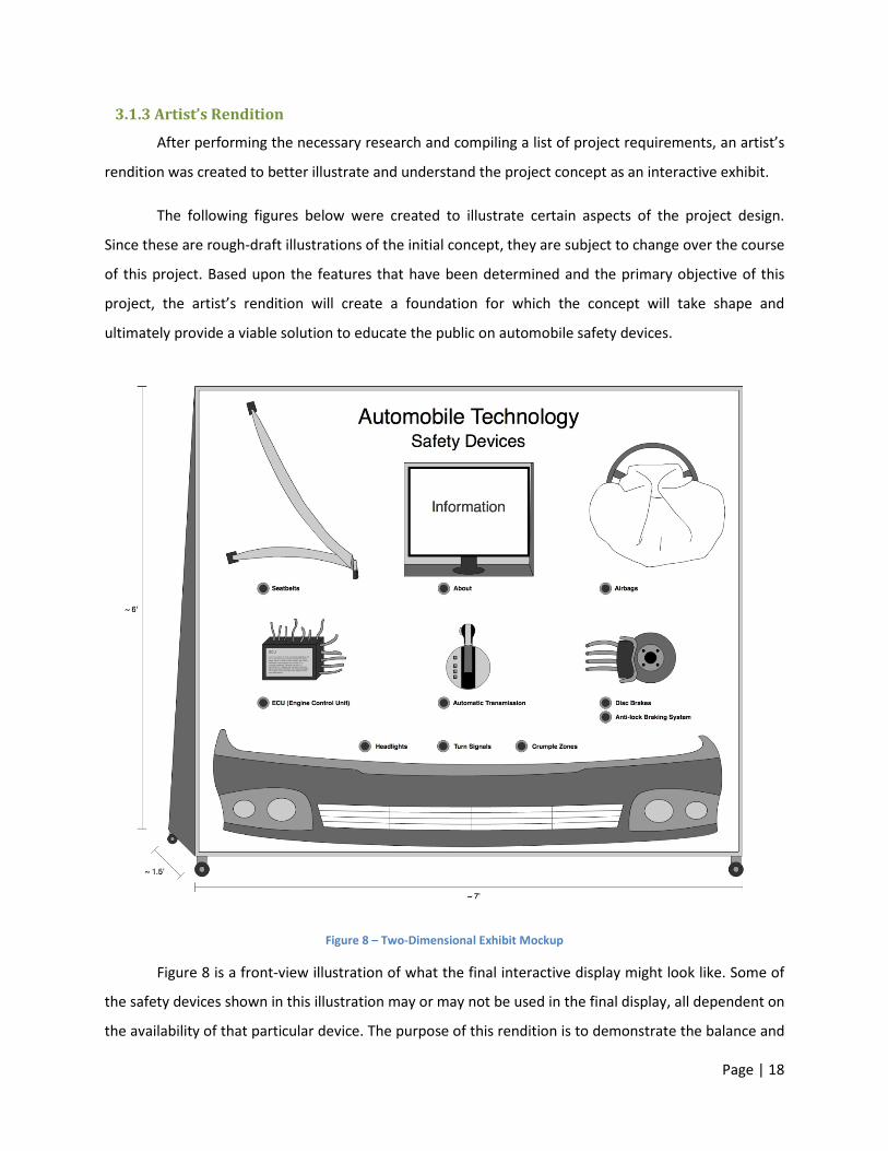
3.1.3 Artist’s Rendition
After performing the necessary research and compiling a list of project requirements, an artist’s
rendition was created to better illustrate and understand the project concept as an interactive exhibit.
The following figures below were created to illustrate certain aspects of the project design.
Since these are rough-draft illustrations of the initial concept, they are subject to change over the course
of this project. Based upon the features that have been determined and the primary objective of this
project, the artist’s rendition will create a foundation for which the concept will take shape and
ultimately provide a viable solution to educate the public on automobile safety devices.
Figure 8 – Two-Dimensional Exhibit Mockup
Figure 8 is a front-view illustration of what the final interactive display might look like. Some of
the safety devices shown in this illustration may or may not be used in the final display, all dependent on
the availability of that particular device. The purpose of this rendition is to demonstrate the balance and
Page | 19
structure of the interactive exhibit. This will be the primary focus area in which the user will interact
with by being able to touch and visualize these safety devices while learning their functionality and
purpose through the related presentation.
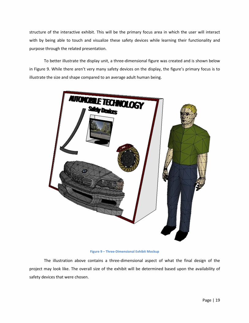
To better illustrate the display unit, a three-dimensional figure was created and is shown below
in Figure 9. While there aren’t very many safety devices on the display, the figure’s primary focus is to
illustrate the size and shape compared to an average adult human being.
Figure 9 – Three-Dimensional Exhibit Mockup
The illustration above contains a three-dimensional aspect of what the final design of the
project may look like. The overall size of the exhibit will be determined based upon the availability of
safety devices that were chosen.
Page | 20
3.2 Presentation Component In order for this project to provide the educational information effectively and efficiently,
software will be used to construct a presentation that will become a part of the exhibit.
The software presentation will be developed through using flash multimedia by incorporating
content gathered throughout our research on each automobile safety device. To provide a rich level of
educational entertainment for the user, a variety of illustrations, videos, and diagrams will be used along
with text-to-speech technology. By combining all these factors, the presentation will become more
engaging and more likely to keep the user’s interest.
Results from the research conducted contained multiple resources of information for each
safety device. With so much content, there lies a risk of developing a presentation that may become
long and tiring for the user. A time constraint was determined for each presentation to not exceed more
than 5-6 minutes. After reaching this threshold, the ability to maintain the user’s interest begins to
deteriorate given the fact that this exhibit is a standing-use interaction. To manage our time more
effectively, a set of guidelines were developed to ensure that the primary objective is met for each
safety device, while maintaining presentation duration less than the determined maximum.
3.2.1 Presentation Criteria
To organize the presentation into a conformed construct, a set of criteria was developed to manage
the design and software implementation. The list below illustrates a set of minimum requirements for
each safety device presentation:
• Safety Device A
o Introduction – Visual aide with vocal support
o Purpose & History – Informative with vocal support
o Functionality – How it works: animations, videos, and/or stills with vocal support
The set of criteria shown above is essential to managing the amount of time and effort that will
be dedicated to each safety device’s presentation, as well as help limit the amount of time each section
of the overall presentation will be displayed for.
Page | 21
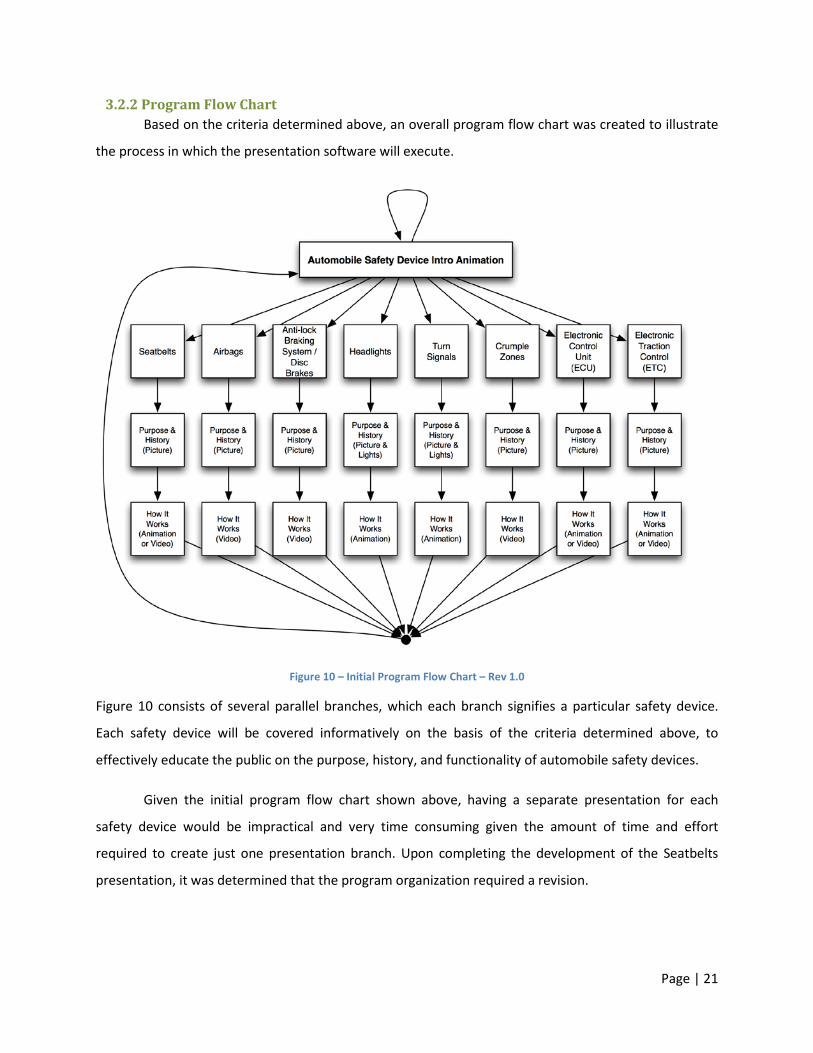
3.2.2 Program Flow Chart Based on the criteria determined above, an overall program flow chart was created to illustrate
the process in which the presentation software will execute.
Figure 10 – Initial Program Flow Chart – Rev 1.0
Figure 10 consists of several parallel branches, which each branch signifies a particular safety device.
Each safety device will be covered informatively on the basis of the criteria determined above, to
effectively educate the public on the purpose, history, and functionality of automobile safety devices.
Given the initial program flow chart shown above, having a separate presentation for each
safety device would be impractical and very time consuming given the amount of time and effort
required to create just one presentation branch. Upon completing the development of the Seatbelts
presentation, it was determined that the program organization required a revision.
Page | 22
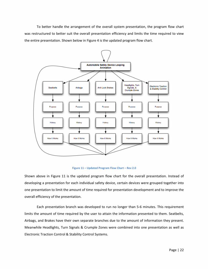
To better handle the arrangement of the overall system presentation, the program flow chart
was restructured to better suit the overall presentation efficiency and limits the time required to view
the entire presentation. Shown below in Figure 4 is the updated program flow chart.
Figure 11 – Updated Program Flow Chart – Rev 2.0
Shown above in Figure 11 is the updated program flow chart for the overall presentation. Instead of
developing a presentation for each individual safety device, certain devices were grouped together into
one presentation to limit the amount of time required for presentation development and to improve the
overall efficiency of the presentation.
Each presentation branch was developed to run no longer than 5-6 minutes. This requirement
limits the amount of time required by the user to attain the information presented to them. Seatbelts,
Airbags, and Brakes have their own separate branches due to the amount of information they present.
Meanwhile Headlights, Turn Signals & Crumple Zones were combined into one presentation as well as
Electronic Traction Control & Stability Control Systems.

Page | 23
3.2.3 Presentation Interface
The interface and experience of the presentations has been carefully tailored to meet the
exhibits needs. The resolution of the monitor to be used in the exhibit is 1280x1024 pixels; the
presentations have been created to this exact resolution to match the aspect ratio and display in the
highest quality possible. The interface of the presentations has been designed to be approachable,
educational, and free of distractions. The presentation interface can be seen below in Figure 12.
Figure 12 – Presentation Interface Illustration
A light skinned British male and dark skinned American female were used as the narrators of the
presentations for diversity and equality. There is a bar along the top to indicate the topic that is
currently being covered as well as a progress indicator that moves as the presentation progresses. A
narrator is present in either the lower left or lower right corner and the source for the media is present
in the corner opposite the narrator. Media that provides a visual to what the narrator is describing is in
the middle and is comprised of still pictures, videos, animations, and animated graphs with data. The
color scheme is refined and simple making heavy use of white, shades of grey, and blue with orange
making some appearances. Helvetica was chosen as the font for its readability and neutrality.
Page | 24
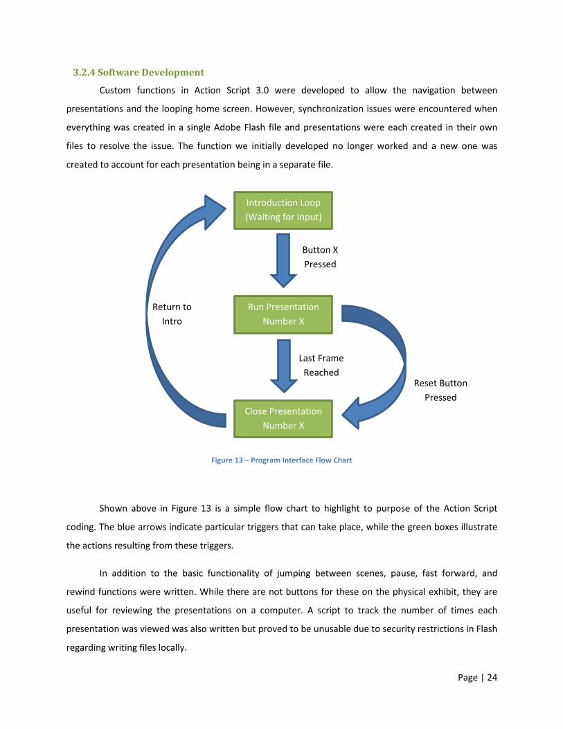
3.2.4 Software Development
Custom functions in Action Script 3.0 were developed to allow the navigation between
presentations and the looping home screen. However, synchronization issues were encountered when
everything was created in a single Adobe Flash file and presentations were each created in their own
files to resolve the issue. The function we initially developed no longer worked and a new one was
created to account for each presentation being in a separate file.
Figure 13 – Program Interface Flow Chart
Shown above in Figure 13 is a simple flow chart to highlight to purpose of the Action Script
coding. The blue arrows indicate particular triggers that can take place, while the green boxes illustrate
the actions resulting from these triggers.
In addition to the basic functionality of jumping between scenes, pause, fast forward, and
rewind functions were written. While there are not buttons for these on the physical exhibit, they are
useful for reviewing the presentations on a computer. A script to track the number of times each
presentation was viewed was also written but proved to be unusable due to security restrictions in Flash
regarding writing files locally.
Introduction Loop (Waiting for Input)
Run Presentation Number X
Button X Pressed
Close Presentation Number X
Last Frame Reached
Return to Intro
Reset Button Pressed

Page | 25
3.2.5 Script Programming
This program was written using the Action Script 3.0 language. Each of the written for this
program can be seen in Appendix B.
Upon running the main program file, a number of steps are executed in our script. The program
is first launched to be in full screen mode and the mouse is hidden from view. An event listener is
created to watch for button inputs (keystrokes). The introductory looping animation is then loaded into
view. When a button input is detected, a loading function gotoPresentations is called which unloads
the currently running presentation and loads the selected one.
In the first frame for each loaded presentation is a navigation function that controls pause, fast
forward, and rewind functionality. It utilizes a Boolean pause variable to know its current state as well as
a frame integer to know its current position. Pause is mapped to the space key, fast-forward by 15
seconds is mapped to the F key, and rewind by 5 seconds is mapped to the R key. In the last frame of
each loaded presentation is a command to stop playing the presentation and call an unload function in
our main program. This unload function unloads the currently playing presentation and loads the
introductory looping animation.
In the main file a statistics function was created to keep track of how many times each
presentation is viewed. Upon each button press an integer is increased by 1 and stored to keep count
for each presentation. The statistics function writes a text file with the current date and time (from a
modified date function) as well as the counts for each presentation. This write is triggered by a
keystroke which we set to be the 8 key. After writing these functions we ran into issues where Flash
uses a window prompt to save the file. The functionality used to exist in Flash to bypass this prompt and
write the file in the background but was removed recently for security reasons. We were unable to find
a workaround to keep track of the statistic in Flash so we decided to use a third party program. A simple
key-logger was installed on the computer that records each keystroke with a date and time stamp. It
appends all the daily keystrokes to a text file at 2am, which we then could analyze for our results.
Page | 26
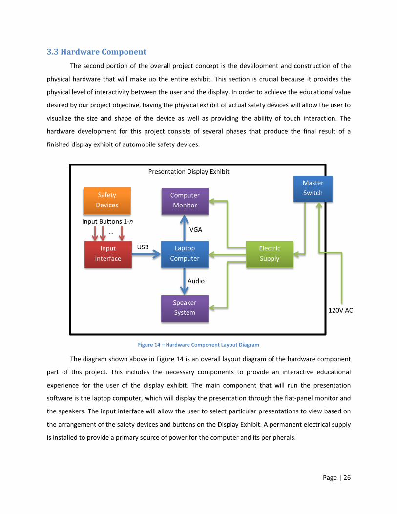
3.3 Hardware Component The second portion of the overall project concept is the development and construction of the
physical hardware that will make up the entire exhibit. This section is crucial because it provides the
physical level of interactivity between the user and the display. In order to achieve the educational value
desired by our project objective, having the physical exhibit of actual safety devices will allow the user to
visualize the size and shape of the device as well as providing the ability of touch interaction. The
hardware development for this project consists of several phases that produce the final result of a
finished display exhibit of automobile safety devices.
Figure 14 – Hardware Component Layout Diagram
The diagram shown above in Figure 14 is an overall layout diagram of the hardware component
part of this project. This includes the necessary components to provide an interactive educational
experience for the user of the display exhibit. The main component that will run the presentation
software is the laptop computer, which will display the presentation through the flat-panel monitor and
the speakers. The input interface will allow the user to select particular presentations to view based on
the arrangement of the safety devices and buttons on the Display Exhibit. A permanent electrical supply
is installed to provide a primary source of power for the computer and its peripherals.
Laptop Computer
Computer Monitor
Input Interface
Speaker System
Electric Supply
Master Switch
Input Buttons 1-n …
120V AC
VGA
Audio
USB
Presentation Display Exhibit
Safety Devices
Page | 27
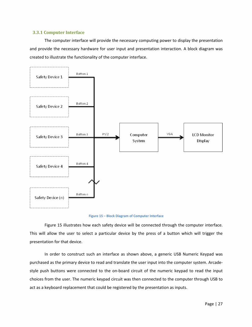
3.3.1 Computer Interface
The computer interface will provide the necessary computing power to display the presentation
and provide the necessary hardware for user input and presentation interaction. A block diagram was
created to illustrate the functionality of the computer interface.
Figure 15 – Block Diagram of Computer Interface
Figure 15 illustrates how each safety device will be connected through the computer interface.
This will allow the user to select a particular device by the press of a button which will trigger the
presentation for that device.
In order to construct such an interface as shown above, a generic USB Numeric Keypad was
purchased as the primary device to read and translate the user input into the computer system. Arcade-
style push buttons were connected to the on-board circuit of the numeric keypad to read the input
choices from the user. The numeric keypad circuit was then connected to the computer through USB to
act as a keyboard replacement that could be registered by the presentation as inputs.
Page | 28
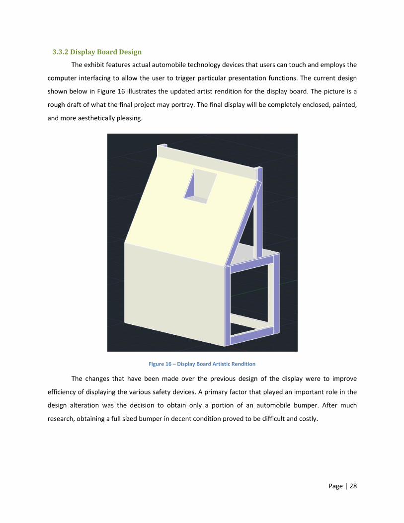
3.3.2 Display Board Design
The exhibit features actual automobile technology devices that users can touch and employs the
computer interfacing to allow the user to trigger particular presentation functions. The current design
shown below in Figure 16 illustrates the updated artist rendition for the display board. The picture is a
rough draft of what the final project may portray. The final display will be completely enclosed, painted,
and more aesthetically pleasing.
Figure 16 – Display Board Artistic Rendition
The changes that have been made over the previous design of the display were to improve
efficiency of displaying the various safety devices. A primary factor that played an important role in the
design alteration was the decision to obtain only a portion of an automobile bumper. After much
research, obtaining a full sized bumper in decent condition proved to be difficult and costly.
Page | 29
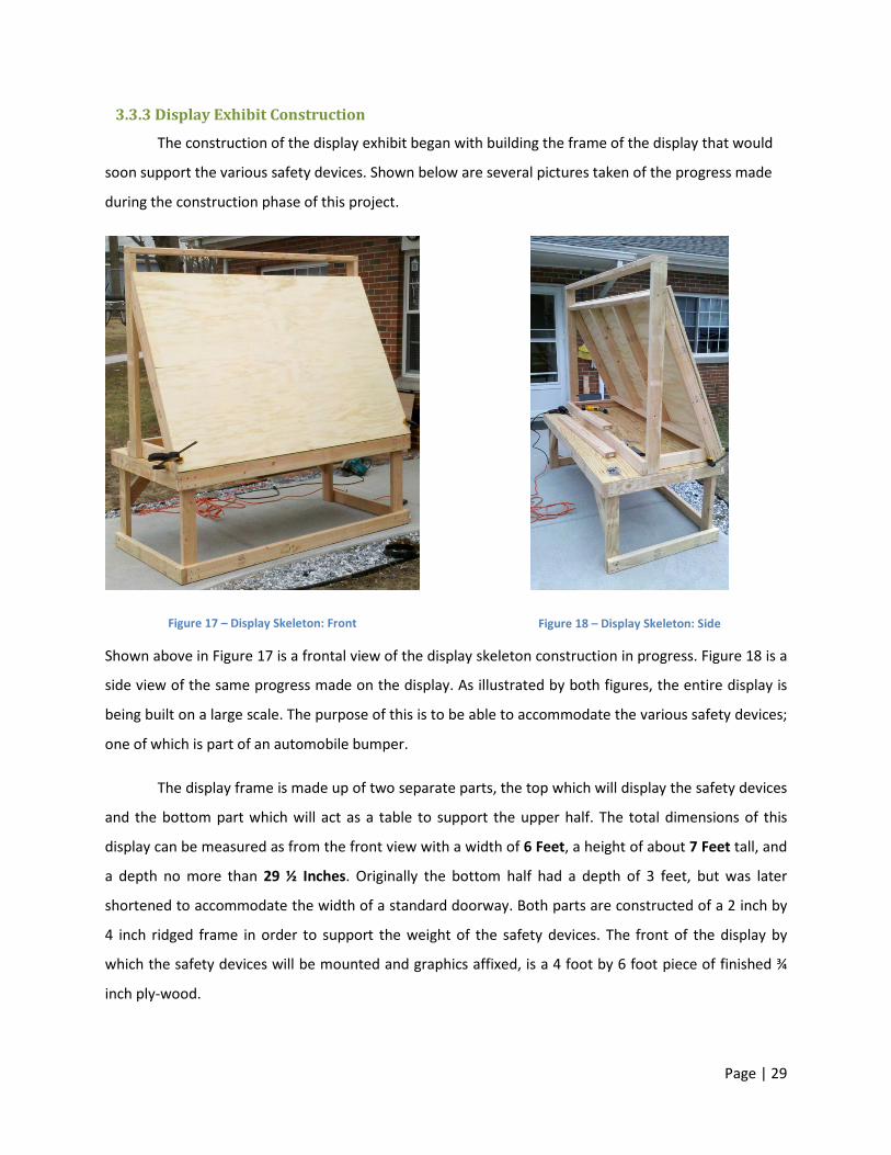
3.3.3 Display Exhibit Construction
The construction of the display exhibit began with building the frame of the display that would
soon support the various safety devices. Shown below are several pictures taken of the progress made
during the construction phase of this project.
Figure 17 – Display Skeleton: Front
Figure 18 – Display Skeleton: Side
Shown above in Figure 17 is a frontal view of the display skeleton construction in progress. Figure 18 is a
side view of the same progress made on the display. As illustrated by both figures, the entire display is
being built on a large scale. The purpose of this is to be able to accommodate the various safety devices;
one of which is part of an automobile bumper.
The display frame is made up of two separate parts, the top which will display the safety devices
and the bottom part which will act as a table to support the upper half. The total dimensions of this
display can be measured as from the front view with a width of 6 Feet, a height of about 7 Feet tall, and
a depth no more than 29 ½ Inches. Originally the bottom half had a depth of 3 feet, but was later
shortened to accommodate the width of a standard doorway. Both parts are constructed of a 2 inch by
4 inch ridged frame in order to support the weight of the safety devices. The front of the display by
which the safety devices will be mounted and graphics affixed, is a 4 foot by 6 foot piece of finished ¾
inch ply-wood.

Page | 30
Proceeding further in the development of the display exhibit, front and side panels were added
to the bottom part of the display. Given the purpose of these facings are solely for aesthetics, 1/8 inch
lauan was used instead of regular ply-wood. The top half of the exhibit was given a cubby-shelf on the
front of the display designated to support the flat-panel monitor for the presentation.
Figure 19 – Display Constructed: Front
Figure 20 – Display Constructed: Rear
Figure 19 and Figure 20 above depict the next stage of progress that had been made on the display
assembly. As noted above, a cubby-shelf had been constructed to support the flat-panel display for the
presentation as well as side panels have been installed to improve aesthetics and hide the inside of the
display unit. Upon finishing the construction of the display, a light colored stain and polyurethane mix
had been added along with trim around the corners of the display to add to the aesthetics and overall
presentation of the display unit.
Along with the changes detailed above, four locking caster wheels were added to the bottom of
the entire display unit to allow for the display to be moved without being lifted. Given the overall design
and construction of the display without the computer system and safety devices mounted to it, the
weight of the constructed wood alone is far greater than one person can carry. While this is the first and
initial design of this project, such accommodations were not taken into consideration but have been
dually noted for future project productions.
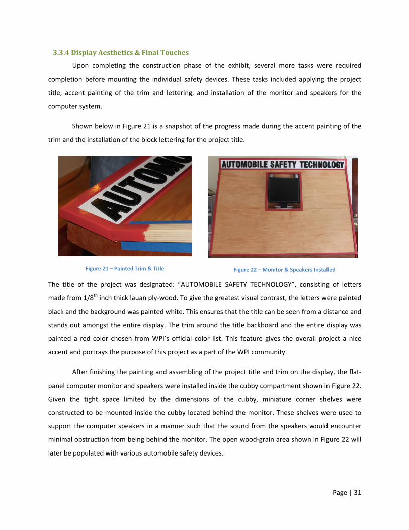
Page | 31
3.3.4 Display Aesthetics & Final Touches
Upon completing the construction phase of the exhibit, several more tasks were required
completion before mounting the individual safety devices. These tasks included applying the project
title, accent painting of the trim and lettering, and installation of the monitor and speakers for the
computer system.
Shown below in Figure 21 is a snapshot of the progress made during the accent painting of the
trim and the installation of the block lettering for the project title.
Figure 21 – Painted Trim & Title
Figure 22 – Monitor & Speakers Installed
The title of the project was designated: “AUTOMOBILE SAFETY TECHNOLOGY”, consisting of letters
made from 1/8th inch thick lauan ply-wood. To give the greatest visual contrast, the letters were painted
black and the background was painted white. This ensures that the title can be seen from a distance and
stands out amongst the entire display. The trim around the title backboard and the entire display was
painted a red color chosen from WPI’s official color list. This feature gives the overall project a nice
accent and portrays the purpose of this project as a part of the WPI community.
After finishing the painting and assembling of the project title and trim on the display, the flat-
panel computer monitor and speakers were installed inside the cubby compartment shown in Figure 22.
Given the tight space limited by the dimensions of the cubby, miniature corner shelves were
constructed to be mounted inside the cubby located behind the monitor. These shelves were used to
support the computer speakers in a manner such that the sound from the speakers would encounter
minimal obstruction from being behind the monitor. The open wood-grain area shown in Figure 22 will
later be populated with various automobile safety devices.
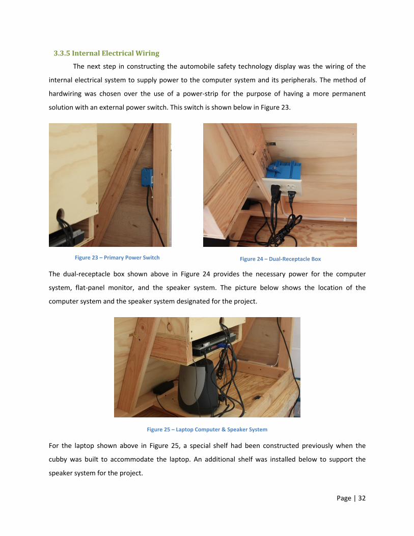
Page | 32
3.3.5 Internal Electrical Wiring
The next step in constructing the automobile safety technology display was the wiring of the
internal electrical system to supply power to the computer system and its peripherals. The method of
hardwiring was chosen over the use of a power-strip for the purpose of having a more permanent
solution with an external power switch. This switch is shown below in Figure 23.
Figure 23 – Primary Power Switch
Figure 24 – Dual-Receptacle Box
The dual-receptacle box shown above in Figure 24 provides the necessary power for the computer
system, flat-panel monitor, and the speaker system. The picture below shows the location of the
computer system and the speaker system designated for the project.
Figure 25 – Laptop Computer & Speaker System
For the laptop shown above in Figure 25, a special shelf had been constructed previously when the
cubby was built to accommodate the laptop. An additional shelf was installed below to support the
speaker system for the project.

Page | 33
3.4 The Safety Devices The most important part of this project includes finding, obtaining, and securing the various
safety devices to the display exhibit. The primary purpose of this feature is to allow the user to touch
and feel the actual devices, and allow them to contract a better visual understanding of what they are.
3.4.1 The Seatbelt
The seatbelt was the first device to be mounted to the display exhibit. It was acquired on eBay
for $20 and is from a mid-1990’s GMC van. It can be seen mounted in Figure 26.
Figure 26 – Seatbelt Mechanism
While many individuals that have previous been in a modern automobile have some familiarity
with a seatbelt, many are unaware of how intricate the inertia-lock mechanism can be given in most
cases it is concealed within the seatbelt column. Another reason for including the seatbelt on the display
exhibit is to ensure how critical the seatbelt can be in preventing injury during an automobile collision.
Page | 34
3.4.2 The Deployed Airbag
The next device mounted to the display exhibit was the deployed airbag. It was acquired from
eBay for $17 and is from a 1995-1998 Ford Windstar. The airbag came un-deployed so we had to come
up with a way to safely deploy it. A stand was constructed to securely hold it during deployment and it
was mounted to it using L brackets. A remote control switch was used to apply a voltage to the igniter
and successfully deploy the airbag. The mounted deployed airbag can be seen below in Figure 27.
Figure 27 – Deployed Airbag Unit
The purpose for including this deployed airbag is to allow the user to gather a perception of what an
actual airbag looks like and feels like. Many drivers and passengers of automobiles have only seen an
airbag in its un-deployed state in which the bag is folded up and packed into a tight enclosure with an
explosive. Another reason for not including an un-deployed airbag unit is for the risk of having a charged
explosive on the display. While the explosive: Sodium Azide – NaN3 is designed to be very stable until it’s
triggered by a charge, there still remains the risk of serious injury for displaying an un-deployed airbag.
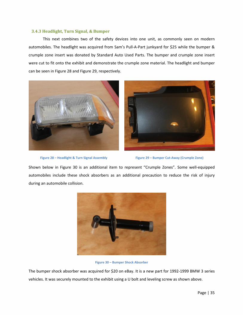
Page | 35
3.4.3 Headlight, Turn Signal, & Bumper
This next combines two of the safety devices into one unit, as commonly seen on modern
automobiles. The headlight was acquired from Sam’s Pull-A-Part junkyard for $25 while the bumper &
crumple zone insert was donated by Standard Auto Used Parts. The bumper and crumple zone insert
were cut to fit onto the exhibit and demonstrate the crumple zone material. The headlight and bumper
can be seen in Figure 28 and Figure 29, respectively.
Figure 28 – Headlight & Turn Signal Assembly
Figure 29 – Bumper Cut-Away (Crumple Zone)
Shown below in Figure 30 is an additional item to represent “Crumple Zones”. Some well-equipped
automobiles include these shock absorbers as an additional precaution to reduce the risk of injury
during an automobile collision.
Figure 30 – Bumper Shock Absorber
The bumper shock absorber was acquired for $20 on eBay. It is a new part for 1992-1999 BMW 3 series
vehicles. It was securely mounted to the exhibit using a U bolt and leveling screw as shown above.

Page | 36
3.4.4 Brake Rotor Assembly
To demonstrate the anti-lock braking system we acquired a brake caliper assembly, brake rotor,
and brake pads. The brake caliper was donated by Standard Auto Used Parts and required extensive
cleaning vinegar and water as well as an enamel spray paint finish. The brake rotor was purchased for
$15 from eBay new and was treated with brake disc cleaner to remove an oily residue. The brake pads
were already in our possession and required modifications to remove a metal clip with prevented them
from being mounted flush on the exhibit. These parts can be seen in Figure 31.
Figure 31 – Brake Rotor Assembly
This brake assembly was included in this project to help the user get a better idea of
understanding the mechanics behind how disc-brakes actually work. We were unable to find an anti-lock
braking hydraulic system to mount on our exhibit but these components were satisfactory in
supplementing our presentation content.
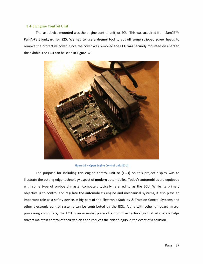
Page | 37
3.4.5 Engine Control Unit
The last device mounted was the engine control unit, or ECU. This was acquired from Sam�s
Pull-A-Part junkyard for $25. We had to use a dremel tool to cut off some stripped screw heads to
remove the protective cover. Once the cover was removed the ECU was securely mounted on risers to
the exhibit. The ECU can be seen in Figure 32.
Figure 32 – Open Engine Control Unit (ECU)
The purpose for including this engine control unit or (ECU) on this project display was to
illustrate the cutting-edge technology aspect of modern automobiles. Today’s automobiles are equipped
with some type of on-board master computer, typically referred to as the ECU. While its primary
objective is to control and regulate the automobile’s engine and mechanical systems, it also plays an
important role as a safety device. A big part of the Electronic Stability & Traction Control Systems and
other electronic control systems can be contributed by the ECU. Along with other on-board micro-
processing computers, the ECU is an essential piece of automotive technology that ultimately helps
drivers maintain control of their vehicles and reduces the risk of injury in the event of a collision.
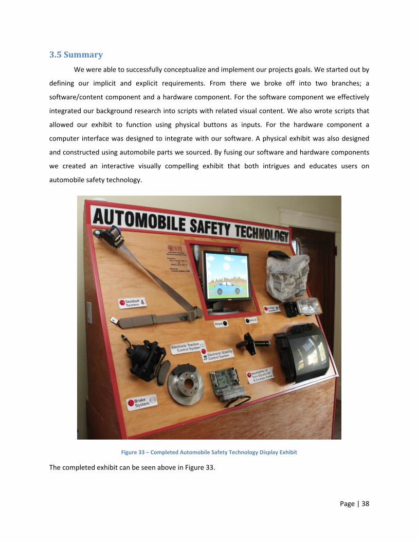
Page | 38
3.5 Summary We were able to successfully conceptualize and implement our projects goals. We started out by
defining our implicit and explicit requirements. From there we broke off into two branches; a
software/content component and a hardware component. For the software component we effectively
integrated our background research into scripts with related visual content. We also wrote scripts that
allowed our exhibit to function using physical buttons as inputs. For the hardware component a
computer interface was designed to integrate with our software. A physical exhibit was also designed
and constructed using automobile parts we sourced. By fusing our software and hardware components
we created an interactive visually compelling exhibit that both intrigues and educates users on
automobile safety technology.
Figure 33 – Completed Automobile Safety Technology Display Exhibit
The completed exhibit can be seen above in Figure 33.
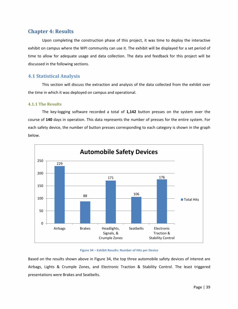
Page | 39
Chapter 4: Results Upon completing the construction phase of this project, it was time to deploy the interactive
exhibit on campus where the WPI community can use it. The exhibit will be displayed for a set period of
time to allow for adequate usage and data collection. The data and feedback for this project will be
discussed in the following sections.
4.1 Statistical Analysis This section will discuss the extraction and analysis of the data collected from the exhibit over
the time in which it was deployed on campus and operational.
4.1.1 The Results
The key-logging software recorded a total of 1,142 button presses on the system over the
course of 140 days in operation. This data represents the number of presses for the entire system. For
each safety device, the number of button presses corresponding to each category is shown in the graph
below.
Figure 34 – Exhibit Results: Number of Hits per Device
Based on the results shown above in Figure 34, the top three automobile safety devices of interest are
Airbags, Lights & Crumple Zones, and Electronic Traction & Stability Control. The least triggered
presentations were Brakes and Seatbelts.
229
88
171
106
176
0
50
100
150
200
250
Airbags Brakes Headlights,Signals, &
Crumple Zones
Seatbelts ElectronicTraction &
Stability Control
Automobile Safety Devices
Total Hits
Page | 40
4.1.2 Analysis
Based on the results shown above, there appears to be a clear indication of which devices are
appearing to be of most interest by the users. Out of the available safety devices on the exhibit, there
are at least two distinguishable groups that are separated by a significant margin.
One group of safety devices that is located on the lower end of the data-plot consists of Brakes
and Seatbelts. While there could be many reasons and variables that play in the role of selection of one
device’s presentation over another, the most likely cause for this group scoring the least hits may be for
simplicity and familiarity reasons. The Seatbelt device is perhaps the most commonly used device in an
automobile and can be regarded as the easiest to understand its functionality and purpose. The braking
system as complex as it is, may be seen as straight-forward concept by many users. In comparison with
the remaining devices on the project display, brakes and seatbelts may be least appealing.
The other group composed of Airbags, Crumple Zones, and Electronic Traction & Stability
Control located on the higher end of the data-plot. From an educational standpoint, one possible cause
for popularity of these devices over the other group may be simply based on the users’ interest in
wanting to learn about these devices given their un-familiarity with them. The complex functionality of
these devices puts them higher on the learning curve, given the amount of technology behind them.
4.1.3 Validity & Discrepancies
While the results derived from the data presented above show some predictable conclusions,
there are several factors that affect the validity of this data.
This data set was recorded using a key-logger program installed on the exhibit’s computer
system. Each safety device’s button was tied to a specific numeric key, in which that corresponding
number triggered its respectful presentation. The program recorded the total number of button presses
corresponding to each safety device’s presentation. Over the given time frame, the total number of hits
per device was recorded above in Figure 34.
Unfortunately, there was no way to distinguish the number of valid button presses from the
number of button presses that occurred when an occasional user pressed a button multiple times. With
the right resources, more sophisticated software can be used to establish more valid data.
Page | 41
4.2 Project Feedback This section will highlight the feedback attained from various faculties, students, and other
members of the WPI community based upon their impressions of this IQP Project Exhibit.
4.2.1 Feedback Survey
After deploying the project display in the WPI Gordon Library, some comments and
recommendations were collected from various members of the WPI community. One particular
recommendation came from one of the librarians:
“It is prom time as well as graduation time at local high schools, so the message to NOT DRINK
AND DRIVE would have been nice (or at least a few scary videos showing crashes).”
If there was adequate time, such a message could have been incorporated into our display presentation.
While our primary goal is to educate the community about automobile safety technology, it is equally
important to understand the risks involved when operating an automobile impaired. Perhaps a future
rendition of this type of project could include such subliminal messages. Another comment that was
received said:
“This is a super project. I can see use in Driver’s Ed programs, police road safety, etc.”
This could be a possible variation with this type of project – deploying an interactive educational
platform in safety programs. Another comment and recommendation provided by a graduate student of
the WPI community said:
“I think that some visitors were impressed to see this IQP in the library, especially those who
were families with prospective students. I do think some considerations for accessibility may be
considered if a future similar project were done or if this were installed in a museum (height of
exhibit not ADA compliant, also since there are many parts/videos, perhaps a chair, where 2
could sit and interact with the display).”
In response to this, there were many valuable lessons learned during the course of this project. One
particular lesson includes re-evaluating and casting size limitations on such a display exhibit. One
possibility is the design of a table-top system that can be moved amongst various locations.
Page | 42
4.3 Future Possibilities & Improvements This section will discuss the possibilities for the future of this project and will highlight areas that
can be improved with this project based on the results and lessons learned.
One of the major areas in which this project could be improved is reducing its size. While its final
size was significantly smaller than the original designs size, it is still too large to easily transport. If we
were to repeat this project we would design it such that it could fit in a standard automobile and sit on a
tabletop instead of having its own stand.
Another area in which this project could be improved is replacing the computer it runs off of
with a slightly more powerful one. The GPU cannot handle displaying the presentations in their native
resolution so it downscales them which results in decreased performance. Using a computer with a
faster GPU would improve the frame rate resulting in smoother playback.
This project has the potential to be used in a variety of other venues. After its residency in the
WPI library, we hope to find a new home for it at another school, library, or museum. Based on our
usage data it has shown itself to be popular amongst WPI students and we think it would be successful
with many different age groups. The combination of the educational presentations and supporting
tactile hardware make it compelling for people of all ages.
If we had additional time to work on this project we would have focused on designing and
optimizing for the web. While it was created in Flash, it was not created for web usage in mind and
would need to be internally restructured/recoded before it would properly function on a web site.
Additionally, it would need to be optimized for size as the files are too large to load quickly on a typical
internet connection.

Page | 43
Chapter 5: Conclusion We started out by defining our objectives to identify important automobile safety devices,
research their purpose and functionality, and find a medium to present this information. After coming
up with these objectives a survey was conducted to assist in finding which automobile safety devices
would be the most worthwhile in researching and presenting. From there automobile safety devices to
cover were chosen and we started conducting in depth background research on each device. Once
background research was completed we focused our efforts on figuring out the best way to convey this
information. We decided upon an interactive physical exhibit that would feature actual automobile
safety device hardware as well as a monitor and speakers to display educational presentations relating
to the displayed hardware.
This phase of our project was broken down into software and hardware components, where the
software included the development of the presentations and infrastructure to support them and the
hardware included the exhibit design, construction, and computer interfacing. Both of these
components were worked on at the same time in addition to sourcing and acquiring automobile safety
devices for the exhibit.
On the software side, presentations were created using the Adobe Flash platform for the
different safety devices selected. For each presentation a script was written and appropriate content
was either found or created for each segment of the script. Functions were written in ActionScript to
allow for the presentations to be linked together and change based on button inputs. An introductory
animation was created for when the exhibit is not actively in use to attract potential users to the exhibit.
On the hardware side, a computer interface was designed to allow for physical buttons to be
mapped to keyboard inputs. The physical exhibit was designed, refined, and constructed. The exhibit
was painted, graphics were created and applied to it, and the automobile safety devices were mounted.
The computer, buttons, and speakers were all wired to a single switch that allowed for the exhibit to be
easily maintained. The computer was set up to log all keystrokes to record usage data and launch the
presentations automatically upon a restart for ease of use.
Upon the completion of both the hardware and software components, a fully functioning
museum quality exhibit had been created. It was placed in the WPI library and usage information was
collected over a period of 140 days. This information has shown the exhibit to be popular amongst the
WPI community. We hope to find the exhibit a new home so that it can continue educating people on
Page | 44
automobile safety technologies. In addition to using our exhibit as a platform for education, a website
has been created to host the presentations to reach a wider audience than the physical exhibit can.
Automobile safety technology is critical to saving lives and we hope that by educating people they will
make safer decisions surrounding automobile acquisitions and operations.
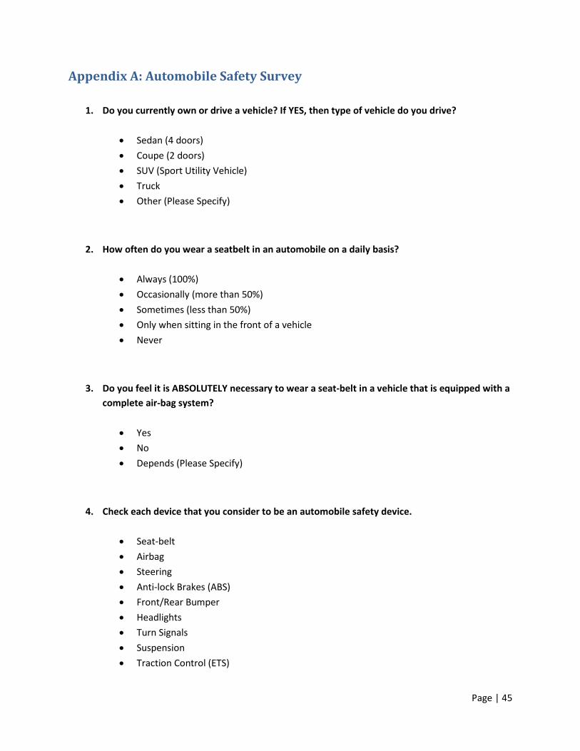
Page | 45
Appendix A: Automobile Safety Survey
1. Do you currently own or drive a vehicle? If YES, then type of vehicle do you drive?
• Sedan (4 doors) • Coupe (2 doors) • SUV (Sport Utility Vehicle) • Truck • Other (Please Specify)
2. How often do you wear a seatbelt in an automobile on a daily basis?
• Always (100%) • Occasionally (more than 50%) • Sometimes (less than 50%) • Only when sitting in the front of a vehicle • Never
3. Do you feel it is ABSOLUTELY necessary to wear a seat-belt in a vehicle that is equipped with a complete air-bag system?
• Yes • No • Depends (Please Specify)
4. Check each device that you consider to be an automobile safety device.
• Seat-belt • Airbag • Steering • Anti-lock Brakes (ABS) • Front/Rear Bumper • Headlights • Turn Signals • Suspension • Traction Control (ETS)
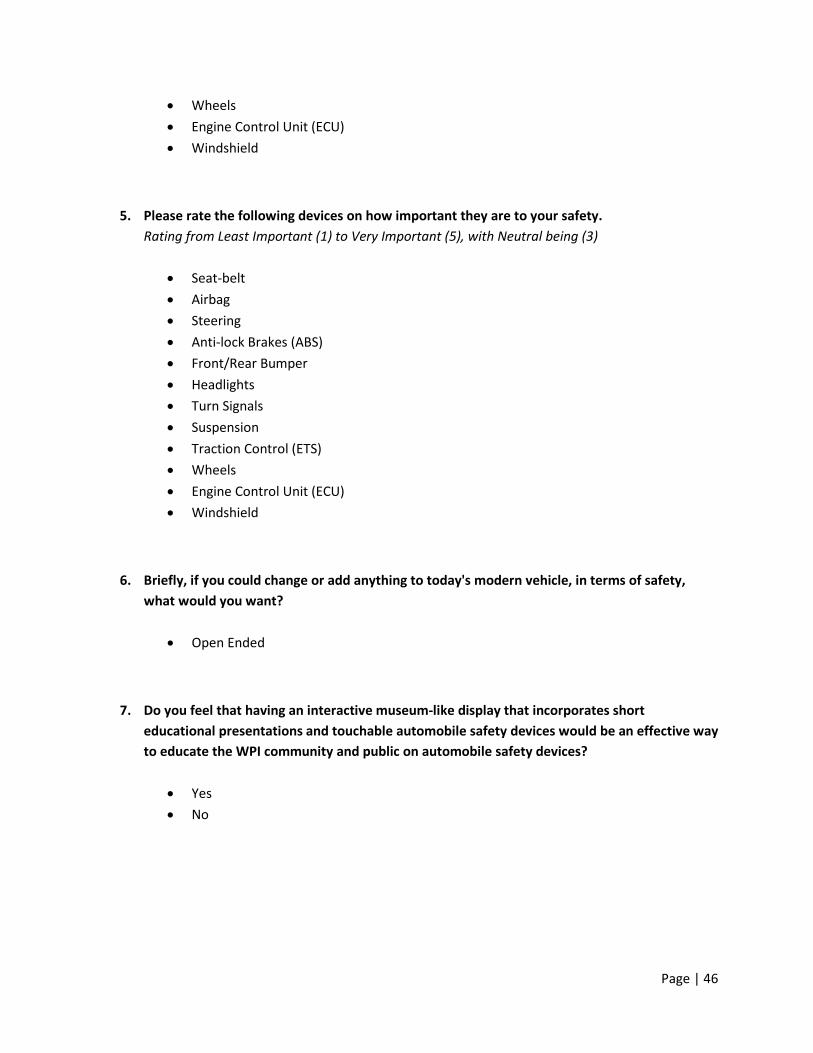
Page | 46
• Wheels • Engine Control Unit (ECU) • Windshield
5. Please rate the following devices on how important they are to your safety. Rating from Least Important (1) to Very Important (5), with Neutral being (3)
• Seat-belt • Airbag • Steering • Anti-lock Brakes (ABS) • Front/Rear Bumper • Headlights • Turn Signals • Suspension • Traction Control (ETS) • Wheels • Engine Control Unit (ECU) • Windshield
6. Briefly, if you could change or add anything to today's modern vehicle, in terms of safety, what would you want?
• Open Ended
7. Do you feel that having an interactive museum-like display that incorporates short educational presentations and touchable automobile safety devices would be an effective way to educate the WPI community and public on automobile safety devices?
• Yes • No

Page | 47
Appendix B: Presentation Action Script Code Main Program Code
// Event Listener for Keypress stage.addEventListener(KeyboardEvent.KEY_DOWN, gotoPresentations); // Enter Full Screen Mode stage.displayState = StageDisplayState.FULL_SCREEN; // Hides mouse cursor Mouse.hide(); // Create External SWF Loader var myLoader:Loader = new Loader(); myLoader.contentLoaderInfo.addEventListener(Event.COMPLETE, onSwfLoad); addChild(myLoader); // Event Listener once presentation is loaded function onSwfLoad(e:Event):void { myLoader.content.addEventListener("SWF_END", function(e:Event) { url = new URLRequest("intro.swf"); myLoader.unloadAndStop(); myLoader.load(url); }); } // Create Statistics Variables var countIntro:int = 0; var countAbout:int = 0; var countAirbags:int = 0; var countBrakes:int = 0; var countLights:int = 0; var countSeatbelts:int = 0; var countTraction:int = 0; var startDate:String = returnDate(0); // Create Statistics File Variable var file:FileReference = new FileReference(); // Load Initial Intro Animation var url:URLRequest = new URLRequest("intro.swf"); myLoader.load(url); // Loading Function function gotoPresentations(event:KeyboardEvent):void { // Intro Animation (Reset), Key = 1 if (event.keyCode==49 || event.keyCode==97) { countIntro = countIntro + 1; url = new URLRequest("intro.swf"); myLoader.unloadAndStop(); myLoader.load(url); } // About Page, Key = 2 if (event.keyCode==50 || event.keyCode==98) { countAbout = countAbout + 1; url = new URLRequest("about.swf"); myLoader.unloadAndStop(); myLoader.load(url); } // Airbags, Key = 3 if (event.keyCode==51 || event.keyCode==99) { countAirbags = countAirbags + 1; url = new URLRequest("airbags.swf"); myLoader.unloadAndStop(); myLoader.load(url); } // Brakes, Key = 4 if (event.keyCode==52 || event.keyCode==100) { countBrakes = countBrakes + 1;
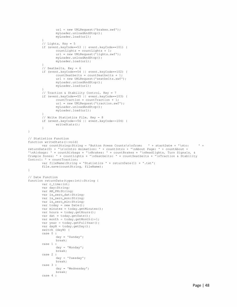
Page | 48
url = new URLRequest("brakes.swf"); myLoader.unloadAndStop(); myLoader.load(url); } // Lights, Key = 5 if (event.keyCode==53 || event.keyCode==101) { countLights = countLights + 1; url = new URLRequest("lights.swf"); myLoader.unloadAndStop(); myLoader.load(url); } // Seatbelts, Key = 6 if (event.keyCode==54 || event.keyCode==102) { countSeatbelts = countSeatbelts + 1; url = new URLRequest("seatbelts.swf"); myLoader.unloadAndStop(); myLoader.load(url); } // Traction & Stability Control, Key = 7 if (event.keyCode==55 || event.keyCode==103) { countTraction = countTraction + 1; url = new URLRequest("traction.swf"); myLoader.unloadAndStop(); myLoader.load(url); } // Write Statistics File, Key = 8 if (event.keyCode==56 || event.keyCode==104) { writeStats(); } } // Statistics Function function writeStats():void{ var countString:String = "Button Press Counts\n\nfrom: " + startDate + "\nto: " + returnDate(0) + "\n\nIntro Animation: " + countIntro + "\nAbout Page: " + countAbout + "\nAirbags: " + countAirbags + "\nBrakes: " + countBrakes + "\nHeadlights, Turn Signals, & Crumple Zones: " + countLights + "\nSeatbelts: " + countSeatbelts + "\nTraction & Stability Control: " + countTraction; var fileName:String = "Statistics " + returnDate(1) + ".txt"; file.save(countString, fileName); } // Date Function function returnDate(type:int):String { var c_time:int; var day:String; var AM_PM:String; var is_zero_dat:String; var is_zero_mon:String; var is_zero_min:String; var today = new Date(); var minutes = today.getMinutes(); var hours = today.getHours(); var dat = today.getDate(); var month = today.getMonth()+1; var year = today.getFullYear(); var dayN = today.getDay(); switch (dayN) { case 0 : day = "Sunday"; break; case 1 : day = "Monday"; break; case 2 : day = "Tuesday"; break; case 3 : day = "Wednesday"; break; case 4 :
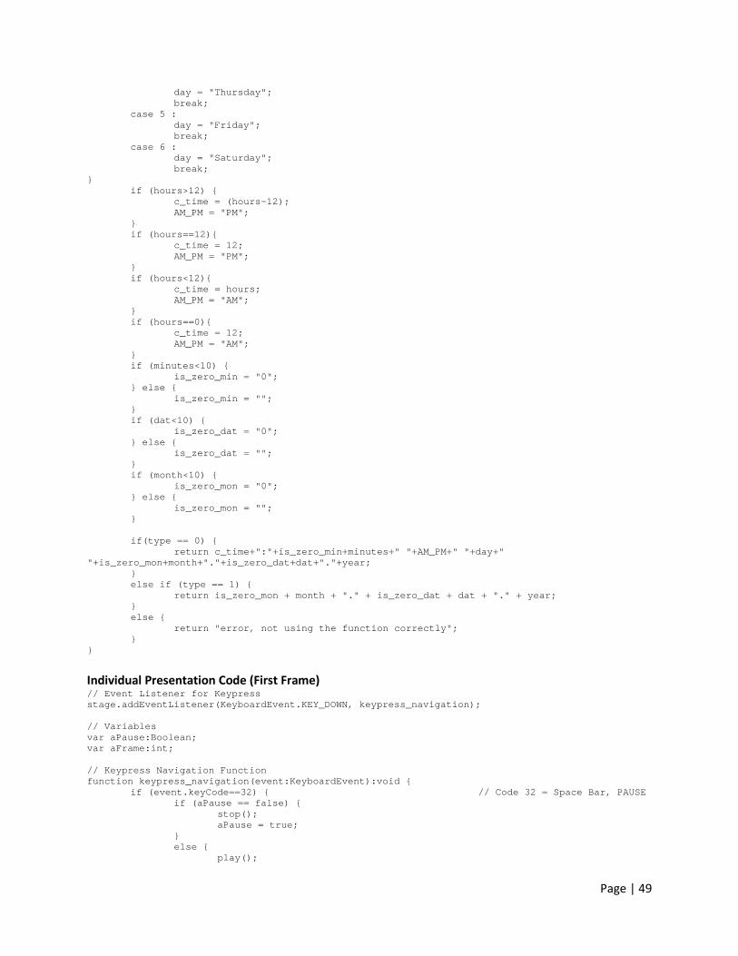
Page | 49
day = "Thursday"; break; case 5 : day = "Friday"; break; case 6 : day = "Saturday"; break; } if (hours>12) { c_time = (hours-12); AM_PM = "PM"; } if (hours==12){ c_time = 12; AM_PM = "PM"; } if (hours<12){ c_time = hours; AM_PM = "AM"; } if (hours==0){ c_time = 12; AM_PM = "AM"; } if (minutes<10) { is_zero_min = "0"; } else { is_zero_min = ""; } if (dat<10) { is_zero_dat = "0"; } else { is_zero_dat = ""; } if (month<10) { is_zero_mon = "0"; } else { is_zero_mon = ""; } if(type == 0) { return c_time+":"+is_zero_min+minutes+" "+AM_PM+" "+day+" "+is_zero_mon+month+"."+is_zero_dat+dat+"."+year; } else if (type == 1) { return is_zero_mon + month + "." + is_zero_dat + dat + "." + year; } else { return "error, not using the function correctly"; } }
Individual Presentation Code (First Frame) // Event Listener for Keypress stage.addEventListener(KeyboardEvent.KEY_DOWN, keypress_navigation); // Variables var aPause:Boolean; var aFrame:int; // Keypress Navigation Function function keypress_navigation(event:KeyboardEvent):void { if (event.keyCode==32) { // Code 32 = Space Bar, PAUSE if (aPause == false) { stop(); aPause = true; } else { play();
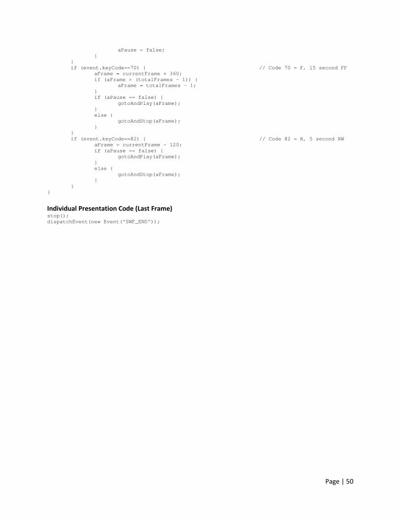
Page | 50
aPause = false; } } if (event.keyCode==70) { // Code 70 = F, 15 second FF aFrame = currentFrame + 360; if (aFrame > (totalFrames - 1)) { aFrame = totalFrames - 1; } if (aPause == false) { gotoAndPlay(aFrame); } else { gotoAndStop(aFrame); } } if (event.keyCode==82) { // Code 82 = R, 5 second RW aFrame = currentFrame - 120; if (aPause == false) { gotoAndPlay(aFrame); } else { gotoAndStop(aFrame); } } }
Individual Presentation Code (Last Frame) stop(); dispatchEvent(new Event("SWF_END"));