Embed Size (px)
Citation preview
Thesis (UAS)
Degree Programme in Information Technology
Computer Networking
2012
Christopher Scicluna
AUTOMOTIVE FACTORY
NETWORK RENEWAL

ii
TURKU UNIVERSITY OF APPLIED SCIENCES, THESIS | Christopher Scicluna
BACHELOR’S THESIS (UAS) │ABSTRACT
TURKU UNIVERSITY OF APPLIED SCIENCES
Degree Programme in IT | Computer Networking
Date of completion of the thesis: 9th September 2012 | Number of pages: 30
Advisor(s): Timo S. Tuominen, Maria Leivo
Christopher Scicluna
AUTOMOTIVE FACTORY NETWORK RENEWAL
The aim of this applied thesis was to plan, implement, and study the upgrading the network infrastructure in Valmet Automotive Oy, specifically in its Uusikaupunki factory. Valmet Automotive is a Finnish automotive service provider, focusing on premium vehicles, convertible roof systems and electric vehicles. The objective was to plan and implement a networking infrastructure that could support the load of a factory in full-scale production, while ensuring near-constant availability. The transition also had to minimize impact on any ongoing car and car part production.
The process was split into four parts: studying the original environment, planning a replacement, implementation, and organizing a support service. Initially a lengthy study of the current network infrastructure was performed, in order to identify the original layout, what needed to be changed and what could be kept. This entailed numerous meetings with engineers responsible for the system, and studying and translating topology maps and technical documentation. This resulted in a detailed picture of the original infrastructure that the author used to compile the migration plan.
The thesis focused around the replacement of the core switches in the Uusikaupunki factory, as this was identified as the most critical and necessary part of the whole project. The impact of replacing these switches was studied, and a step by step process plan was developed in order to lessen any negative effects on production. This process had to include providing component redundancy, satisfy original network requirements, and create a support structure for the new infrastructure.
This thesis resulted in increased reliability and performance on the IT infrastructure of the Uusikaupunki branch of Valmet Automotive Inc. Network breaks and speed decreases, that were observed beforehand, were shown to have minimized. The knowledge gained from this thesis was used to plan a similar implementation in another of Valmet’s branches.
KEYWORDS:
network renewal, car factory, core switch, redundancy, failover, monitoring, support systems

iii
TURKU UNIVERSITY OF APPLIED SCIENCES, THESIS | Christopher Scicluna
TABLE OF CONTENTS
1 INTRODUCTION 1
1.1 Term definition 2
2 ORIGINAL INFRASTRUCTURE ANALYSIS 3
2.1 Original network infrastructure 3
2.2 Existing Hardware review 5
2.3 Pros and Cons of current infrastructure 7
3 INFRASTRUCTURE RENEWAL PLAN 9
3.1 Planning a replacement 9
3.1.1 Gathering documentation 9
4 PHYSICAL IMPLEMENTATION 14
4.2 Physical cable Migration 14
5 SUPPORT STRUCTURE 23
5.1 Support contract 23
5.2 Monitoring: Connectivity, Ports, Uptime 23
6 CONCLUSION 25
7 SOURCES 26
2.1.1 Physical Topology 3
2.1.2 Logical topology 4
2.2.1 Central Switch 5
2.2.2 Distribution Switches: 6
2.2.3 Access Switches: 6
3.1.2 Initial Switch Configuration 10
3.1.4 Migrating Layer 3 settings 11
4.2.1 Optic Fiber migration 15
4.3.2 Copper-based media migration 17

1
TURKU UNIVERSITY OF APPLIED SCIENCES, THESIS | Christopher Scicluna
1 Introduction
This is a computer networking-oriented thesis that centers on the network infrastructure
of an automotive company. This thesis was commissioned by Valmet Automotive Inc,
an automotive service provider. Dealing with premium vehicles, its main areas of
interest are engineering, car manufacturing, roof systems and business consulting. It
employs around 1700 professionals worldwide.
There was a need to replace major and central parts of this infrastructure without
impacting car production or user network access. The core-layer switch is the main
focus of this thesis, as it is a critical part of the car production process with several
systems depending on it for data transfer and processing, monitoring and reporting.
The end-of-life period of the current hardware in use had long passed, and symptoms
of its age had started to become apparent in the form of increased network downtime.
This was the main problem that this thesis tried to resolve.
The goals of this thesis are to investigate and implement a flexible and reliable solution
to satisfy the network requirements of an expanding automotive company. This solution
has to take into considerations current requirements as well as future needs.
Additionally, any implemented solution has to be fault-tolerant, and a support system
for it needs to be designed and discussed.
In order to complete this objective, the work was split into the following sections:
1. Document all Alcatel settings (VLANs, routing, etc) and all connections to other
switches around the factory.
2. Create migration plan
a. This will include Layer 2, Layer 3 and Layer 4 switching.
b. Legacy features in the existing central switch also need to be supported
and implemented.
c. Legacy hardware can be replaced where necessary.
3. Implement above plan and test for any problems.
4. Create a support service infrastructure for the new setup.
5. Create documentation of all results achieved.
The hardware provider chosen to provide the replacement was Hewlett-Packard Inc.,
and this thesis focuses on the successful implantation of hardware obtained from this

2
TURKU UNIVERSITY OF APPLIED SCIENCES, THESIS | Christopher Scicluna
company and decommissioning of existing hardware. This thesis will not detail the
provider competition and selection process since these choices had already been
made before the thesis was started.
1.1 Term definition
Network Address Translation (NAT): This service translates an IP address to another
IP address. It is normally used to allow users with a private IP address in a LAN access
to a public address network WAN, such as used in large networks. NAT can also serve
in conserving private IP addresses, as a single public IP address can translate to many
different private IP addresses.
Patch Panel: These terminate cables running throughout the building in female network
ports. They are normally placed in server or switch racks and switches and clients are
connected to them instead of passing direct cables from switch to switch.
3
TURKU UNIVERSITY OF APPLIED SCIENCES, THESIS | Christopher Scicluna
2 Original infrastructure analysis
2.1 Original network infrastructure
The existing network in Valmet Automotive’s Uusikaupunki factory is the essential
underlying infrastructure for multiple systems including Active Directory domain-based
logins, car production monitoring, logistics ordering and tracking, client global network
links, and a wireless network infrastructure. The topology was altered as company
needs grew, and modifications were documented. Maintenance for this system was
outsourced to a third party company, and all actions implemented on the system had to
be reported and reviewed.
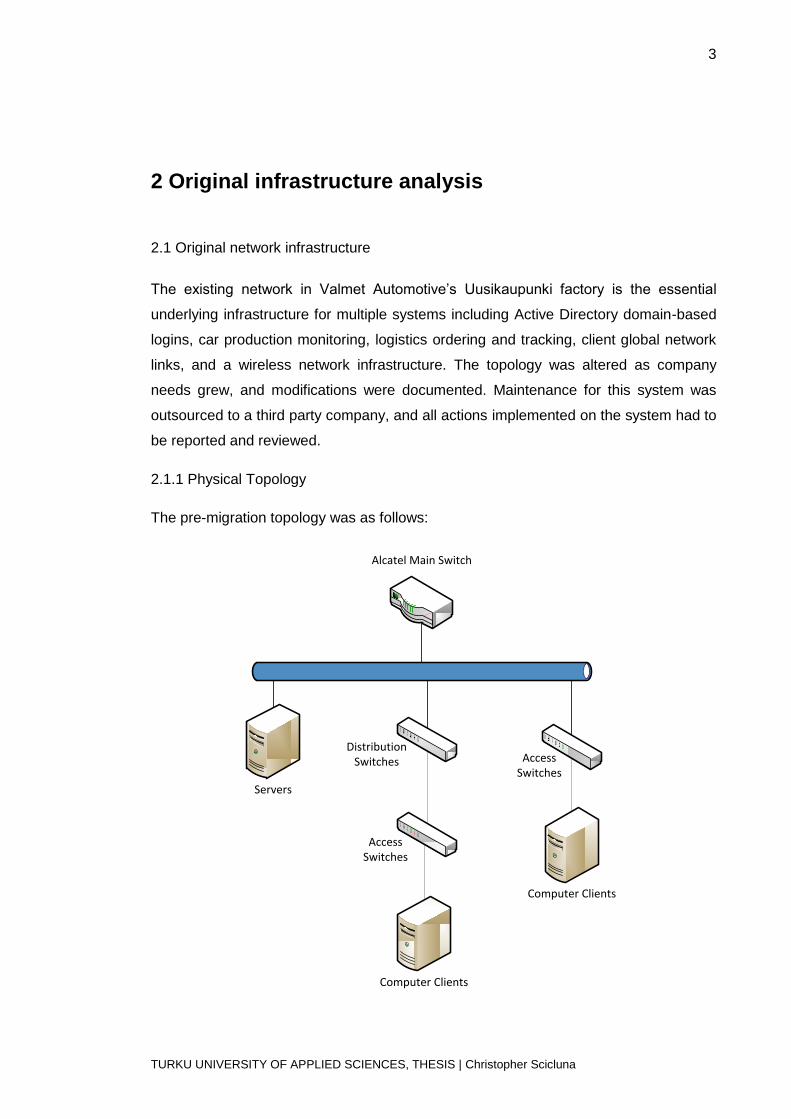
2.1.1 Physical Topology
The pre-migration topology was as follows:
Alcatel Main Switch
Access Switches
Distribution Switches
Access Switches
Computer Clients
Servers
Computer Clients

4
TURKU UNIVERSITY OF APPLIED SCIENCES, THESIS | Christopher Scicluna
This topology was designed initially in the late 1990s and gradually modified by the
local IT service delivery team as needs arose. This is a tree network topology, where
the central node has links connected to both servers and other switches. As one can
observe from the above topology, there is one centralized Alcatel switch node and two
main HP 5406zl child nodes. There are also numerous second level child nodes
connected to the main switch, the reason for this being physical cabling limitations of
this size of factory. The physical links from access layer switches throughout the
factory terminated in the server room and the distribution layer switches. These were
fibre cables that supported 1Gbit links. Connections from one node to the next were
also realized using 1Gbit fiber links.
In the server room, all devices were connected to the main switch. Servers had
redundant links, but not all were in use, and most were connected using 1Gbit Ethernet
copper links. The ESX hosts were also connected in this manner, and users were
complaining of a lack of speed when performing live Virtual Machine migration.
2.1.2 Logical topology
Numerous Layer 2 VLANS exist in the current topology, each service a different
network for multiple customers, processes, etc. Additionally, a number of VLANS were
used as Demilitarized Zones (DMZ) between the Valmet network and other third party
networks. VLANs were assigned using Tagged / Untagged modes: if a VLAN is tagged
on a specific port, that VLAN is then passed on that link. This is known as adding an
802.1q tag to a VLAN. Subsequent switches that are VLAN aware can then handle
these VLANS and assign VLANs to be Untagged on that VLAN, or further trunk the
VLAN. In this way, multiple networks could be distributed throughout the large factory
space, and a device could be connected to any network without any Layer 3 routing
necessary. The Alcatel main switch handled Layer 3 routing for some of these
networks, whereas other networks had their own routing hardware. All Layer 2
switching was performed by Valmet hardware.
Multiple Layer 3 networks existed and were required by different car production
systems, car manufacturers, IP camera surveillance programs, and a number of other
needs. Routing between these networks was handled by the Alcatel main switch. The
default route lead to MetsoNet, via a DMZ network, as Valmet Automotive is a part of
Metso group and all internet traffic passes through Metso firewalls and filters. Policy-
based routing was also in effect. NAT rules and other Layer 3 and 4 rules routed traffic
5
TURKU UNIVERSITY OF APPLIED SCIENCES, THESIS | Christopher Scicluna
from different service providers to the machines and servers that they support. It was
not possible to publish the specifics of these rules on this thesis.
2.2 Existing Hardware review
An appraisal of the current network setup was conducted in order to isolate high-risk
hardware and prioritize their replacement. The information gained from this review is
listed in this section.
2.2.1 Central Switch
Alcatel OmniSwitch 7800
The central node of the network infrastructure was an Alcatel OmniSwitch 7800. This is
a modular switch chassis, managed with a web management toolkit called WebView. It
had 2 Controller cards on which the configuration was stored, and 4 Power Units for
redundancy. There were also installed two 12-port 100Mbit fiber modules, three 12-port
Gigabit fiber modules, three 12-port Gigabit Ethernet modules, and five 24-port 10/100
Mbit modules. Many end devices were connected to this switch and VLANs were
tagged or untagged on these links as necessary.
The Alcatel main switch was acting as a Layer 3 router, and numerous of these VLANS
had VLAN interfaces configured on the main switch. These interfaces were used as a
default gateway on the multiple client devices found in Valmet’s premises. Static routes
were also present and were used to forward data based on the client network’s needs.
Different metrics were assigned to each of these routes in order to assign how far the
destination network is from the Alcatel.
The Alcatel main switch also acted as a Multilayer switch by performing Layer 4
routing. Policy-based routing on the main switch combined conditions and actions in
order to create a rule, which decided how data can be handled. A condition could be
based on Port, Layer2, Layer 3 or Layer 4 criteria. Each criterion could be grouped, so
one condition could be created to apply to multiple IP networks, or multiple TCP ports.
Actions defined what would be performed on data: Load balancing, Network Address
Translation, Quality of Service, Routing or Access Control List. Conditions and actions
came together in the Alcatel switch to create a Rule. Any data that was intercepted by
a condition in a rule would be subject to the action present in that rule. For example,
6
TURKU UNIVERSITY OF APPLIED SCIENCES, THESIS | Christopher Scicluna
any OFTP traffic destined to a certain network, with a certain source, would be
redirected to a server that could handle that traffic.
This server had reached its end of lifetime and service could not be obtained.
Therefore, it was needed to replace this switch in order to provide a reliable network
infrastructure core.
2.2.2 Distribution Switches:
HP 5406zl Modular Switch
This modular switches can be modified depending on the needs of the specific
installation location. Modules can be installed that change the capability of the switch.
The modules can vary the amount of copper or fiber connections, as well as provide
different network speed (100Mbps, 1Gbps or 10Gbps). Additionally, these switches had
installed a Wireless LAN controller module each, which provided central management
of the numerous amount of wireless Access Points throughout the factory. These
controllers were teamed together to provide failover capabilities for the WLAN
infrastructure. There are also two power supplies on this hardware to provide additional
failover. The configuration of this switch could be accomplished over a WebGUI or a
telnet / console CLI connection.
This hardware had not reached its end of lifetime and was still under an active support
contract, so the decision was taken not to replace it.
2.2.3 Access Switches:
HP Procurve 2650 Switch series
These formed the mainstay of the switches used to connect hosts to the network. The
switches had 48 auto-sensing 10/100Mbit RJ-45 ports (10/100 Base-T) and 2 dual-
personality ports, which can be used as RJ-45 Gigabit Ethernet ports or open mini-
GBIC slot for transceivers to enable fiber connectivity. While the megabit Ethernet ports
were used by hosts to reach their respective networks, the dual-sensing ports were
used to connect to the next switch node in the topology. They achieved this using
multiple Gigabit fiber connection, which was beneficial due to the large distances
between switches in the factory. The configuration of these switches could also be
performed via WebGUI or CLI over telnet.
7
TURKU UNIVERSITY OF APPLIED SCIENCES, THESIS | Christopher Scicluna
Interoperability with the new main switch was tested, and it resulted that none of these
switches had to be replaced as a part of this migration, since all were compatible with
newer technologies.
3COM SuperStack II 1100 Switches
These stackable switches were also in use in certain parts of the factory for host
connections. They can support 12 or 24 Ethernet 10Base-T connections and
2 100Base-T ports, as well as being upgradeable with modules. These modules had
installed 100Base-FX Fiber connections. The advantage of using 100Base-FX is that
optic fibers can span a greater distance, at 2kms using full duplex multimode fibers.
This distance was not needed in this current infrastructure.
Interoperability testing revealed that these switches were incompatible with the fiber
interfaces on the new main switch. Therefore, these switches had to be replaced and it
was decided their replacement would be the above HP Procurve 2650 switches. Their
replacement is discussed in the planning and implementation section of this thesis.
2.3 Pros and Cons of current infrastructure
A fair appraisal of the network system, as it was functioning before this project was
started, would not be complete without analyzing the advantages and disadvantages of
said system. The result of this analysis was then used to determine what needs to be
replaced or rebuilt, so as to avoid any unnecessary or harmful changes.
2.3.1 Advantages
The tree topology allows for easy network extension. In a rapidly growing infrastructure
such as Valmet’s, the tree network topology allows bringing network availability to any
point in the network. It also has the advantage of allowing spanning large distances
without extremely long cable lengths, since it uses access switches as network
repeaters.
The Alcatel Switch web interface was functional and easy to use and learn. The GUI
interface had all options and the local team rarely had to rely on remembering /
researching complex console commands, even for complex tasks such as Policy
Based rules. Subsequently, the local team was very familiar with simple and
complicated operations on this switch, and no training was necessary for them to
perform day-to-day support tasks.
8
TURKU UNIVERSITY OF APPLIED SCIENCES, THESIS | Christopher Scicluna
2.3.2 Disadvantages
The main problems of the current infrastructure were related to the age of the
hardware, especially that of the main switch. Since a tree topology relies on a central
node, any failure of this node would cause a failure in the whole topology; therefore this
node has to be fully protected against any downtime. Critical errors were being
observed on the Alcatel which were hard to debug, and the lack of support experts on
this hardware compounded to the problem. Additionally, there was a lack of modules
that could be offered, especially 10Gigabit Interfaces, and replacement modules for
existing ones that might need to be replaced in case of hardware failure. This had to be
resolved in order to maintain a reliable network service for the factory.
9
TURKU UNIVERSITY OF APPLIED SCIENCES, THESIS | Christopher Scicluna
3 Infrastructure renewal plan
This section deals with the decisions taken to provide Valmet Automotive with an
upgraded core switch.
3.1 Planning a replacement
The decision was taken before starting this thesis to purchase a replacement core
switch, and this was handled by Valmet’s purchasing department. The purchasing and
competition process ended with the decision to purchase an HP product, specifically a
switch from the HP A7500 Series. Formerly known as the H3C S7506E, the name
changed when HP purchased the H3C Company and started giving support for its
services through selected partners, of which Valmet Automotive had already service
contracts with. Additionally, multiple HP Procurve 2610 switches were purchased in
order to replace old 3COM 1100 switches throughout the factory.
The main switch migration process was planned in the following steps:
1. Gathering all documentation about old infrastructure
2. Initial switch configuration
3. Migrating Layer 2 settings
4. Physical fiber & Ethernet cable migration
5. Migrating Layer 3 settings
6. Migrating Policy-based rules
The following section of the thesis will go over these steps in detail.
3.1.1 Gathering documentation
It was planned that before starting any migration plan, there should be all information
about the old infrastructure collected in one place. A document repository was created
and all information pertaining to the network structure was collected. This information
included VLAN listings, IP and addressing tables, routing tables, topology maps, CAD
cabling drawings, and cable types. This documentation was studied in order to get the
best idea of how the current network infrastructure worked and what improvements
could be implemented. It was discovered that not all networks, for instance, needed to

10
TURKU UNIVERSITY OF APPLIED SCIENCES, THESIS | Christopher Scicluna
be migrated as some were out of use and could be decommissioned. This information
was confirmed by having numerous meetings with current network support staff and
administrators in order to get the latest picture of the network infrastructure.
3.1.2 Initial Switch Configuration
Two HP A7500 Series switches were obtained, as described above, and installed in a
server room rack. The switches were teamed so that configuration could be prepared
from one location. All configurations were accomplished via the CLI, since the WebGUI
lacked in offering some features, such as the above mentioned teaming function. This
teaming process was implemented via the IRF (Intelligent Resilient Framework)
technology, whereby the switches were connected together to create one virtual switch.
One switch was designated as the master, and each member in the team had to be
assigned a Unique ID. Two 10Gigabit Ethernet ports were selected from each member
switch and teamed together to provide failover. After physically connecting the switches
together, a Layer 3 interface was created and a telnet connection to this IP was tested
and established. After this process the switches could be treated as one switch, with
1/x/x/x to signify the first module and 2/x/x/x to signify the second.
Other initial configurations included enabling SSH and disabling telnet to enhance
security, changing access usernames and passwords, and allowing FTP access. The
latter option was enabled in order to allow regularly scheduled backups to be taken of
the working switch configuration. All access was secured by creating an Access
Control list to limit connections directed from the local LAN only. Login idle timeout and
SNMP access was also configured.
11
TURKU UNIVERSITY OF APPLIED SCIENCES, THESIS | Christopher Scicluna
3.1.3 Migrating Layer 2 settings
The general plan for this step was as follows:
1. Plan physical cable migration :
a. List all port definitions, where they connect that are not used anymore
b. List where cables go on new switch, any special requirements of ports
(speed, duplex, etc)
2. Create trunk port between H3C and Alcatel to pass all VLANs.
3. Configure access and trunk ports on H3C to match settings on Alcatel.
4. Configure port-based VLAN associations.
All VLAN definitions, excluding VLAN interfaces, were planned to be migrated in this
step. Additionally, any specific port settings would also be migrated. In this intermediate
process, it was planned that the old and new switches will be connected together with
two gigabit Ethernet fiber links, one for the management VLAN and the other for all the
other VLANs. At this point in time, the H3C will handle all Layer 2 communications
while the Alcatel will still be doing Layer 3 routing. This will enable moving the physical
ports one at a time with minimal downtime. There were no port-based rules in the old
switch, so all ports could be moved without affecting traffic. Additional access layer
switches were put into use to separate client access hosts from the main switch.
Downtime planning was carried out on a per-link basis, and special care was taken
when migrating switch links that had child nodes themselves. It was planned at this
stage to migrate all server fiber links to 10 gigabit Ethernet although these servers had
redundant NICs connecting them to the main switch so downtime planning was more
easily accomplished. The aim of this step was to effectively turn the old main switch
into a “stub router”, also known as a “router on a stick” or “one armed router”, where
the router (old Alcatel) is only connected to the switch (new HP) with one link and does
all the Layer 3 functions.
3.1.4 Migrating Layer 3 settings
This step involves moving the Layer 3 networking operations to the new switch. These
are Layer 3 virtual interfaces to provide interoperability between different networks.
Directly connected interface and static routes would be migrated in this section
separately, and reliability checks would be carried out after every step. VLAN interfaces
had directly connected routes automatically configured when added to the main switch,
12
TURKU UNIVERSITY OF APPLIED SCIENCES, THESIS | Christopher Scicluna
and on most VLANs the switch was acting as the default gateway for these networks.
Dynamic routing protocols were not present on the old Alcatel switch, as these were
handled by other routers in separate networks.
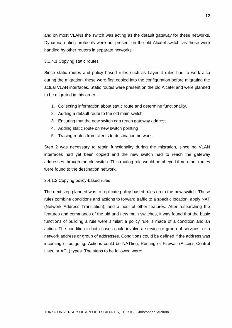
3.1.4.1 Copying static routes
Since static routes and policy based rules such as Layer 4 rules had to work also
during the migration, these were first copied into the configuration before migrating the
actual VLAN interfaces. Static routes were present on the old Alcatel and were planned
to be migrated in this order:
1. Collecting information about static route and determine functionality.
2. Adding a default route to the old main switch.
3. Ensuring that the new switch can reach gateway address.
4. Adding static route on new switch pointing
5. Tracing routes from clients to destination network.
Step 2 was necessary to retain functionality during the migration, since no VLAN
interfaces had yet been copied and the new switch had to reach the gateway
addresses through the old switch. This routing rule would be obeyed if no other routes
were found to the destination network.
3.4.1.2 Copying policy-based rules
The next step planned was to replicate policy-based rules on to the new switch. These
rules combine conditions and actions to forward traffic to a specific location, apply NAT
(Network Address Translation), and a host of other features. After researching the
features and commands of the old and new main switches, it was found that the basic
functions of building a rule were similar: a policy rule is made of a condition and an
action. The condition in both cases could involve a service or group of services, or a
network address or group of addresses. Conditions could be defined if the address was
incoming or outgoing. Actions could be NATting, Routing or Firewall (Access Control
Lists, or ACL) types. The steps to be followed were:

13
TURKU UNIVERSITY OF APPLIED SCIENCES, THESIS | Christopher Scicluna
1. List all policy-based rules. Research each rule as to what it does and its effects.
2. Copy the condition and the action details on to the new switch
a. Define services, networks, and groups. These are objects used to create
conditions or define NAT, routing or ACL actions.
3. Combine these two to create a policy rule on the new switch.
3.1.4.5 Migrating VLAN interfaces
It must be noted here that at this point, all Layer 3 traffic was still handled by the old
Alcatel since the gateway addresses of all VLAN interfaces was still there. This would
change however, once the VLAN interface was moved to the new switch. As was
mentioned before, uptime had to be maximized even during this migration, so the order
of VLAN migration was important. However, users were informed of possible downtime
as times of least network usage. It was planned that directly connected routes would be
migrated by taking the following steps per VLAN:
1. Collect and review all Layer 3 documentation.
2. Inform main users & about possible downtime
3. Create a disabled VLAN interface with the same VLAN ID on the new switch
4. Copy over same settings to this VLAN interface.
5. During planned downtime, disable VLAN interface on old Alcatel
6. Enable VLAN interface on HP.
7. For the migrated network, create static route on old Alcatel pointing towards
new HP switch. This would ensure that the network that had not yet been
migrated could maintain functionality.
8. Test functionality.
This approach would be taken on a different basis per network, and key users per
network can be consulted as to the correct functionality of devices in the network being
migrated. Using this plan it is possible to revert back to using the old switch during any
step of the process by reversing the above steps. The final step would be to disconnect
completely the old main switch completely from the network.

14
TURKU UNIVERSITY OF APPLIED SCIENCES, THESIS | Christopher Scicluna
4 Physical Implementation
The above plan was followed as closely as possible, and with every step the migration
scenario was tested. Some unforeseen problems were detected; these and the solution
taken to overcome them will be listed here.
4.1 Initial Switch configuration
SSH, Teaming, Name, Management IP, Useful Commands
Teaming commands were performed as follows
irf-port 1/1
port group interface Ten-GigabitEthernet1/2/0/1 mode normal
port group interface Ten-GigabitEthernet1/2/0/2 mode normal
irf-port 2/2
port group interface Ten-GigabitEthernet2/2/0/1 mode normal
port group interface Ten-GigabitEthernet2/2/0/2 mode normal
interface Vlan-interface1
description vlan1
ip address <omitted>
4.2 Physical cable Migration
This section defines how physical cables were migrated away from the old switch. All
fiber optic cables leading to other switches were migrated to slots on the new central
switch, and new LC-ST or LC-SC fibre optic cables were purchased for this purpose.
There were numerous copper-based Ethernet connections fom servers to the central
switch, and a number of these were migrated to new access layer switches installed in
the server room. Patch panels, fiber and copper based, were present throughout the
factory, and were used to make long distance connections. In this way, an access
switch could be connected to the central switch, another switch or a client PC in a more
flexible manner. The next sections will detail the process by which the cables were
migrated.

15
TURKU UNIVERSITY OF APPLIED SCIENCES, THESIS | Christopher Scicluna
4.2.1 Optic Fiber migration
4.2.1.1 Connectivity Testing
There were numerous models of access layer switches in the factory, and while most
were upgraded there still existed legacy models. It was necessary to test all access
layer switches compatibility with the new HP central switch, and this was achieved in
the following manner:
a. A spare switch of the same make and model was configured with the same
settings as one of the production switches.
b. This switch was connected to the new central switch via fibre. Fibre cables
with different connectors were used depending on the switch: LC to LC for
newer HP switches and LC to SC for older 3COM models.
c. Two clients were connected to the test access switch and new central switch
respectively.
d. Connectivity testing was executed between the client PCs.
It was discovered that compatibility issues existed to older 3COM and Xylan switches.
These switches use 100Mbps-FX (Ethernet fibre) modules to connect to the Alcatel
switch, which had a 12 port module that supported these connections. The result of the
above testing was that these devices were incompatible since 3com 1100 switches
have 100Base-FX which runs at 1100Nm wavelength, and H3C installed transceivers
run at 1000Base-SX which use 850Nm wavelength.
The solutions presented for the above problem were to:
a. Purchase compatible modules for new central switch. The module needed
was a 12 Port 100Base-FX Fiber modules.
b. Replace affected switches with newer, compatible HP switches that have
1000Base-SX interfaces.
The solution B was chosen, and newer HP switches were purchased to replace the
older 3COM switches. These had LC connections on 1000Base-SX interfaces, and the
cable maximum possible distance was reduced from using the older 100Base-FX
fibers. However, the distances from switch to switch were not great enough for this to
be an issue. The new switches were configured in the same way as the old switches:
VLANs were tagged on the trunk port to the central switch / next switch node and
16
TURKU UNIVERSITY OF APPLIED SCIENCES, THESIS | Christopher Scicluna
untagged on client access ports. They were then physically installed to replace the
outdated 3com switches in switch cabinets throughout the factory.
The new switch also offered 10Gbit Ethernet as a new technology over the old switch.
This was used with 3 virtual server hosts, and 10Gigabit Ethernet modules were
purchased for this purpose. Connectivity was tested by creating a virtual switch in
VMware with a 10Gbit interface attached, configuring this interface to connect to the
same network as the regular interfaces, and moving a test virtual machine to this virtual
switch. This test was successful and all ESX hosts were enabled to use 10Gbit links.
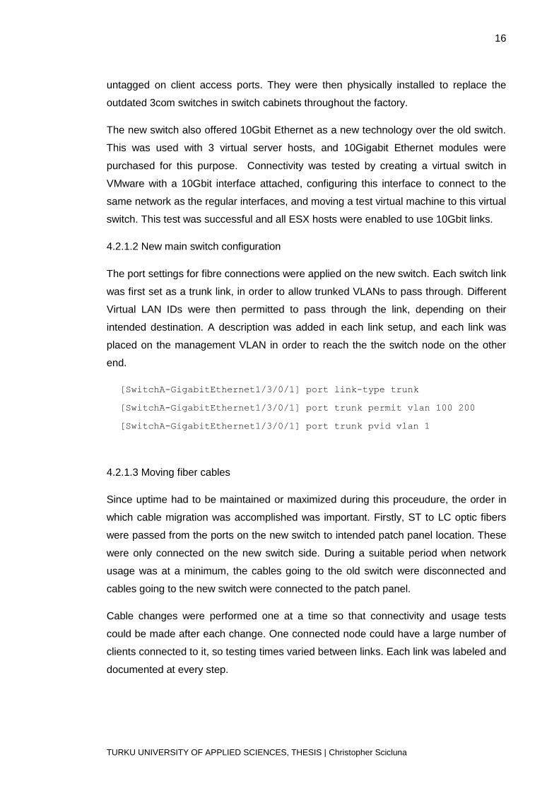
4.2.1.2 New main switch configuration
The port settings for fibre connections were applied on the new switch. Each switch link
was first set as a trunk link, in order to allow trunked VLANs to pass through. Different
Virtual LAN IDs were then permitted to pass through the link, depending on their
intended destination. A description was added in each link setup, and each link was
placed on the management VLAN in order to reach the the switch node on the other
end.
[SwitchA-GigabitEthernet1/3/0/1] port link-type trunk
[SwitchA-GigabitEthernet1/3/0/1] port trunk permit vlan 100 200
[SwitchA-GigabitEthernet1/3/0/1] port trunk pvid vlan 1
4.2.1.3 Moving fiber cables
Since uptime had to be maintained or maximized during this proceudure, the order in
which cable migration was accomplished was important. Firstly, ST to LC optic fibers
were passed from the ports on the new switch to intended patch panel location. These
were only connected on the new switch side. During a suitable period when network
usage was at a minimum, the cables going to the old switch were disconnected and
cables going to the new switch were connected to the patch panel.
Cable changes were performed one at a time so that connectivity and usage tests
could be made after each change. One connected node could have a large number of
clients connected to it, so testing times varied between links. Each link was labeled and
documented at every step.

17
TURKU UNIVERSITY OF APPLIED SCIENCES, THESIS | Christopher Scicluna
4.3.2 Copper-based media migration
4.3.2.1 Connectivity Testing
The same procedure as above was used to test interconnectivity between devices
using copper-based media. These devices were mainly servers found in the server
room. Since the new main switch Ethernet interfaces could support 10, 100 or 1000
Megabit connections, no issues were met in migrating ports over from the old switch to
the new.
4.3.2.2 New switch configuration
Port configuration in this stage was carried out in using scripts and ranges, owing to the
fact of an increased number of ports to configure. A description was added to each link,
as well as a label and an entry in the documentation manual.
4.3.2.4 Moving copper cables
Owing to the size and large number of copper cables, cable management racks were
created (using the services of some personnel resources from Valmet). These were
used to reliable pass the copper cables from the new main switch to the intended
destination. New cables were used for this purpose in order to increase the lifetime of
this migration.
End device types connected with copper cables varied between routers, switches,
servers and normal computers. All external connections to other networks were made
with copper cables, and these were migrated first. The order of moving links was the
same as with fiber cables: cables were passed from the new switch to the end device /
patch panel, connected on designated port on the new switch, and then replaced on
the end device / patch panel during designated downtime. Connectivity was tested and
ensured after each link was moved.

18
TURKU UNIVERSITY OF APPLIED SCIENCES, THESIS | Christopher Scicluna
4.2 Logical Configuration Migration – Layer 3 & 4
On starting this phase of the project, the old main switch was acting as a one-handed
router (also known as router-on-a-stick), handling all layer 3 communications. The next
step was to migrate upper layer settings without affecting network connectivity. The
migration order taken was:
1 Static routes
2 Policy-based routes, NAT and ACL
3 VLAN interfaces
The steps taken will be described below:
4.1 Migrating Static routes
All routes found on the central switch were static routes, and dynamic routes were not
implemented as they were handled by separated devices. A list of all static routes was
listed from the documentation obtained in the steps described above. This list was then
reviewed with Valmet network engineers and altered / pruned when routes were found
to be incorrect or unnecessary. The rules were configured onto the new main switch as
follows.
Configuring a default route
<SwitchA> system-view
[SwitchA] ip route-static 0.0.0.0 0.0.0.0 1.2.3.4
Adding static routes for subnet
[SwitchA] ip route-static 193.73.2.0 255.255.255.0 23.3.1.2
[SwitchA] ip route-static 193.73.3.0 24 23.3.1.2
Adding static routes for only one host
[SwitchA] ip route-static 193.73.2.4 255.255.255.255 23.3.1.2
It was discovered that the default route had to be added before all other routes. This
static route would forward all traffic to the Alcatel. Since a static route needed to
contact the gateway IP address directly through an interface, all static routes were
added after the VLAN interfaces were installed below. Connectivity testing was
performed after adding each route, both from the switch itself, the source and the target
network, using ping and traceroute commands.

19
TURKU UNIVERSITY OF APPLIED SCIENCES, THESIS | Christopher Scicluna
4.2 Policy-based routes, NAT and ACL
In the old Alcatel switch, policy routes were gathered under one section of the web
based GUI, and worked in such a way that an action was performed if it matched a
condition. As described in Chapter 3, a condition specified the parameters examined by
the switch, and the action specified what the switch will do when it detects data flow
matching this condition. These actions could be ACL (Access Control Lists) that block
or allow data, NAT (Network Address Translation) that translate an IP address or range
into another address or range, or Routing that routes a specific IP address or range to
a certain gateway.
In the new HP A7500 switch, these actions had to be considered separately as the
commands and controls to create these rules were of a different status. Each policy-
based rule had to be considered separately, as it was transformed into either an ACL,
policy-based route, or a NAT rule on the new switch.
4.2.1 Access Control Lists (ACL)
ACLs were used by themselves to block or allow traffic, or as a condition to apply some
action on specific data. An ACL on the HP A7500 operating system could be specified
as Basic, Advanced or Ethernet Frame. A Basic ACL only affects traffic from a source
specific network or host, and no protocol parameters or destinations can be applied.
This compromised the majority of ACL rules, and had to be numbered between 2000
and 2999. Advanced ACLs can filter traffic based on source or destination IP address
or network, and can also filter protocols, Type of Service (ToS) and IP precedence. The
latter two features of advanced ACLs were not needed in this migration. An advanced
ACL had to have a number between 3000 and 3999. Ethernet Frame Header ACLs
filtered traffic based on Layer 2 parameters, such as VLAN, MAC address, or any link-
layer protocol type. These ACLs were tested but were not used at all in this migration.
A wildcard mask had to be used instead of a subnet mask, and this was achieved by
taking the binary inverse of the subnet mask.
Standard ACL
[SwitchA] acl number 2001
[SwitchA] rule 0 permit source 10.0.0.0 0.0.255.255
[SwitchA] quit
20
TURKU UNIVERSITY OF APPLIED SCIENCES, THESIS | Christopher Scicluna
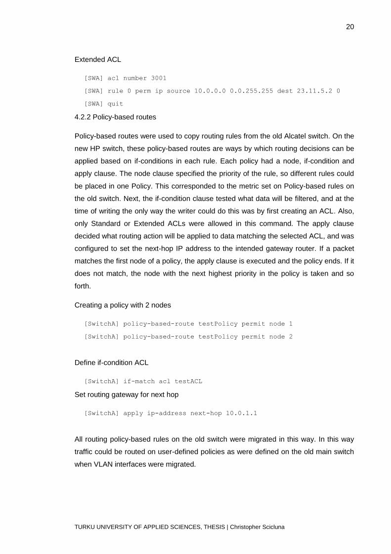
Extended ACL
[SWA] acl number 3001
[SWA] rule 0 perm ip source 10.0.0.0 0.0.255.255 dest 23.11.5.2 0
[SWA] quit
4.2.2 Policy-based routes
Policy-based routes were used to copy routing rules from the old Alcatel switch. On the
new HP switch, these policy-based routes are ways by which routing decisions can be
applied based on if-conditions in each rule. Each policy had a node, if-condition and
apply clause. The node clause specified the priority of the rule, so different rules could
be placed in one Policy. This corresponded to the metric set on Policy-based rules on
the old switch. Next, the if-condition clause tested what data will be filtered, and at the
time of writing the only way the writer could do this was by first creating an ACL. Also,
only Standard or Extended ACLs were allowed in this command. The apply clause
decided what routing action will be applied to data matching the selected ACL, and was
configured to set the next-hop IP address to the intended gateway router. If a packet
matches the first node of a policy, the apply clause is executed and the policy ends. If it
does not match, the node with the next highest priority in the policy is taken and so
forth.
Creating a policy with 2 nodes
[SwitchA] policy-based-route testPolicy permit node 1
[SwitchA] policy-based-route testPolicy permit node 2
Define if-condition ACL
[SwitchA] if-match acl testACL
Set routing gateway for next hop
[SwitchA] apply ip-address next-hop 10.0.1.1
All routing policy-based rules on the old switch were migrated in this way. In this way
traffic could be routed on user-defined policies as were defined on the old main switch
when VLAN interfaces were migrated.

21
TURKU UNIVERSITY OF APPLIED SCIENCES, THESIS | Christopher Scicluna
4.2.3 Network Address Translation (NAT)
As defined in the introduction section, NAT translates an IP address in a packet header
to another IP address. Normally, this is used to allow private IP addresses to access
external public networks; however, in this project there were different requirements.
Rules existed that required changing the destination IP address of traffic destined to a
specific server, so that this traffic is routed elsewhere. Other rules changed the source
IP address of a single host to a specific address required by a special application.
Therefore, dynamic NAT had to be used to associate an ACL with an address or an
address pool. The ACL would specify what addresses were translated if traffic matched
the conditions specified within. Therefore, these were created first. Extended ACLs
were created since all ACLs associated with NAT had source and destination criteria.
Creating a dynamic NAT with an ACL
Create ACL
[SwitchA] acl number 3002
[SwitchA-acl-adv-3005] rule permit ip source 10.0.0.0 0.0.0.255
destination 3.2.3.1 0
[SwitchA-acl-adv-3005] quit
Create Address Pool
[SwitchA] nat address-group 0 172.3.4.4 172.3.4.5
Associate ACL and Address pool with interface
[SwitchA] interface vlan 2
[SwitchA-Vlan-interface2] nat outbound 2001 address-group 0
[SwitchA-Vlan-interface2] quit

22
TURKU UNIVERSITY OF APPLIED SCIENCES, THESIS | Christopher Scicluna
4.3 Migrating VLAN interfaces
VLAN interfaces were up to this point on the main switch, but as static routes and other
Layer 3 settings were already moved, traffic could be now handled with the new HP
switch. VLAN interfaces were being used as gateway addresses for the most port for
LANs inside the factory, but also as DMZ interfaces between the Valmet internal
network and a customer network. The process was followed as described in the
planning phase, by creating all VLAN interfaces on the new switch then enabling them
during an advertised time when users were told to save their work as a precautionary
measure.
Creating a VLAN interface
[SwitchA] interface Vlan-interface 102
[SwitchA-Vlan-interface100] ip address 172.16.1.1 24
[SwitchA-Vlan-interface100] quit
Displaying all VLAN interfaces
[SwitchA] display interface Vlan-interface brief
4.4 Finishing up
The final step was to move all remaining static routes to the new switch, as until now
only directly connected routes were available. After each static route was added, the
old router was configured to point to the new switch for each static route move. Finally,
the default route on the old switch was made to point to the new switch.

23
TURKU UNIVERSITY OF APPLIED SCIENCES, THESIS | Christopher Scicluna
5 Support structure
After finalizing all the new infrastructure changes and ensuring that network
connectivity was stable, a support structure had to be discussed. This was essential as
an operational network infrastructure of a large automotive factory is needed for normal
day-to-day operations. The criteria for choosing a support partner were researched and
discussed with other members of the IT Infrastructure team.
5.1 Support contract
A support contract, or Service Level Agreement, was discussed in order to give support
for immediate problems that may arise concerning the network infrastructure. Since
downtime would impact car production, network infrastructure support had to be fast
responding and knowledgeable. The responsibility of a support team would include
diagnosing and fixing simple problems as well as performing routine maintenance
tasks, such as assigning ports to specific VLANs or ensuring connectivity. The support
team also needed to elevate problems that it could not handle to a Valmet network
engineer.
Valmet Automotive has a long standing relationship with Fujitsu Services to provide IT
support services. A support agreement for the existing network hardware was already
in place; however, the support team lacked the experience with new network hardware
that was installed. In order to alleviate this problem, training sessions were planned for
the support team. These sessions would go over the deployed hardware and topology
changes, new commands that support staff might need, monitoring tools used to detect
a problem, and what needs to be performed in case of power-failure. The training
sessions would be held over the course of the summer, and would also incorporate
visits by HP experts or training courses. The documentation of exact changes would
also be published and distributed to all support personnel.
5.2 Monitoring: Connectivity, Ports, Uptime
A network infrastructure of this size has a large number of nodes and as such it would
be extremely time-consuming to monitor functionality of every switch. Without any
monitoring solution, networking problems would be discovered by the symptoms, and

24
TURKU UNIVERSITY OF APPLIED SCIENCES, THESIS | Christopher Scicluna
at that time it is normally too late and production has already been impacted in some
form. Therefore, a system had to be implemented that would constantly monitor all the
nodes and node’s attributes to provide an early warning of impending problems.
The monitoring program chosen was Nagios Core, as it was already deployed and
configured within Valmet’s network infrastructure. Originally chosen because of its
open source-based GPL license, Nagios Core monitors hosts and services running on
them for functionality, and alerts users when a break is detected. Many different types
of alerts could be configured, and emails were currently being used to alert support
personnel. Additionally, a tactical overview is shown so the whole network can be
monitored from one easy to use web page. Nagios was re-configured to add the new
hardware, and alerts were configured so that support staff was alerted directly once a
problem is detected. Schedules were also configured as agreed upon in the service
agreement; however, the network administrator received alerts at any time. Hosts on
different networks were monitored, and Nagios was also set up to review bandwidth on
heavily loaded links. A list of common problems that could be reported by Nagios was
listed and discussed with the support staff, in order to find the best and fastest solution.
If a support person was working on a problem, he would enter an update on the Nagios
internal website next to the reported problem. This update would include details such
as problem source and action being taken.

25
TURKU UNIVERSITY OF APPLIED SCIENCES, THESIS | Christopher Scicluna
6 Conclusion
The original purpose was to analyze Valmet Automotive’s network infrastructure in
Uusikaupunki to replace the central switch controlling network functionality while
maintaining high levels of uptime during this process, and to provide a reliable, stable
and fast network infrastructure for the whole factory and offices. The main features of
this applied thesis were successfully applied, and now the car factory is utilizing a new
main switch that has yet to show any operational problems. Additionally, all monitoring
solutions and the documentation produced, as well as the planned support structure,
will help ensure than any network issues are detected and resolved quickly and
efficiently. Creating the support structure was delayed due to timing and training
issues, and training sessions had been scheduled for the support staff ahead of this
thesis.
In order to minimize the impact of any hardware problems, the central switch
compromised of two teamed chassis to provide failover of any controller module or
power supply. This would give the support team adequate time to install a replacement.
Additionally, an HP-registered service partner was chosen as the supplier for any parts,
as was defined in the warranty of the hardware chosen.
Future implementations to the network hardware were considered and discussed, and
the most pressing task after the end of this project would be upgrading the access-
layer switches around the factory. A redesign of the subnet topology was also
discussed, especially by implementing Virtual Length Subnet Masks for offices,
management, and other sections of the factory. Finally, it was planned that the lessons
learnt from this thesis would be implemented during a similar operation in Valmet’s
other car factories in Zary, Poland and Osnabrück, Germany.
These above implementations, while building on the work attained in this thesis, would
need their own analysis and planning, and development time would need to be
allocated accordingly.

26
TURKU UNIVERSITY OF APPLIED SCIENCES, THESIS | Christopher Scicluna
7 Sources
1 - Hiles, Andrew. 2002. The Complete Guide to IT Service Level Agreements, Third
Edition. Rothstein Associates Inc
2 - Barth, Wolfgang. 2008. Nagios: System and Network Monitoring, Second Edition.
Open Source Press
3 - Alcatel OmniSwitch 7800 Hardware User Guide. Consulted 15.5.2012
http://enterprise.alcatel-lucent.com/docs/?id=11296
4 - Alcatel OmniSwitch CLI Reference Guide. Consulted 15.5.2012
http://enterprise.alcatel-lucent.com/docs/?id=19012
5 - Alcatel OmniSwitch 7800 Advanced Routing Guide. Consulted 15.5.2012
http://enterprise.alcatel-lucent.com/docs/?id=16851
6 - H3C S7500 Series Operation Manual (Release 3100 Series). Consulted 20.5.2012
http://www.h3c.com/portal/download.do?id=121180
7 - H3C S7500 Series Command Manual (Release 3100 Series). Consulted 20.5.2012
http://www.h3c.com/portal/download.do?id=120872
8 - H3C S7500 Series Ethernet Switches Configuration Examples Release
3135(V1.00). Consulted 20.5.2012
http://www.h3c.com/portal/download.do?id=143973