Embed Size (px)
Citation preview

Autonomous Jumping Microrobots
Sarah BergbreiterPh.D. Qualifying Exam
June 23, 2005
Department of Electrical Engineering and Computer Science, UC Berkeley

2/41
Overview
• Motivation and Previous Work• Jumping for Locomotion• Robot Design
– Actuation– Energy Storage– Power – Control
• Fabrication and Integration
3/41
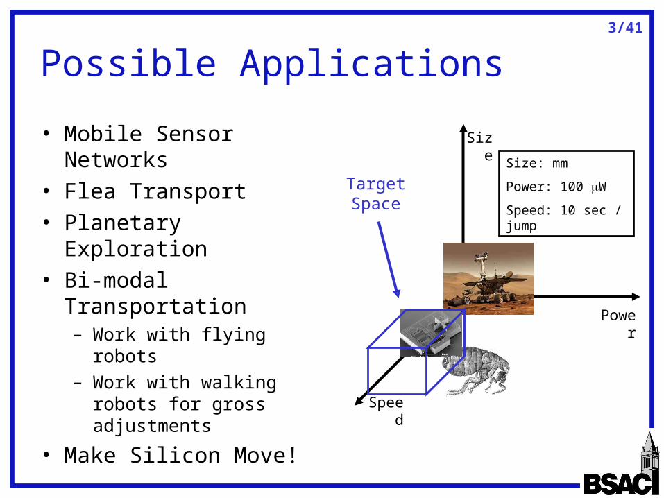
Possible Applications
• Mobile Sensor Networks
• Flea Transport• Planetary Exploration• Bi-modal
Transportation– Work with flying robots– Work with walking
robots for gross adjustments
• Make Silicon Move!
Size
Power
Speed
Target Space
Size: mm
Power: 100 W
Speed: 10 sec / jump
4/41
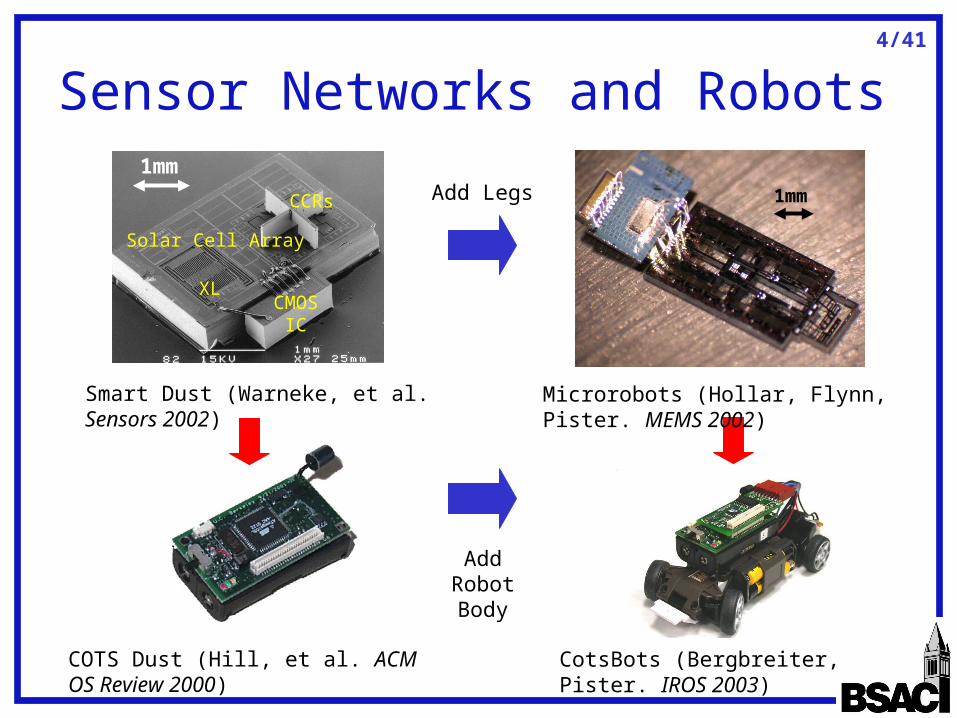
Sensor Networks and Robots
Solar Cell Array
CCRs
XLCMOS
IC
Smart Dust (Warneke, et al. Sensors 2002) Microrobots (Hollar, Flynn, Pister. MEMS 2002)
Add Legs
Add Robot Body
1mm1mm
COTS Dust (Hill, et al. ACM OS Review 2000) CotsBots (Bergbreiter, Pister. IROS 2003)
5/41
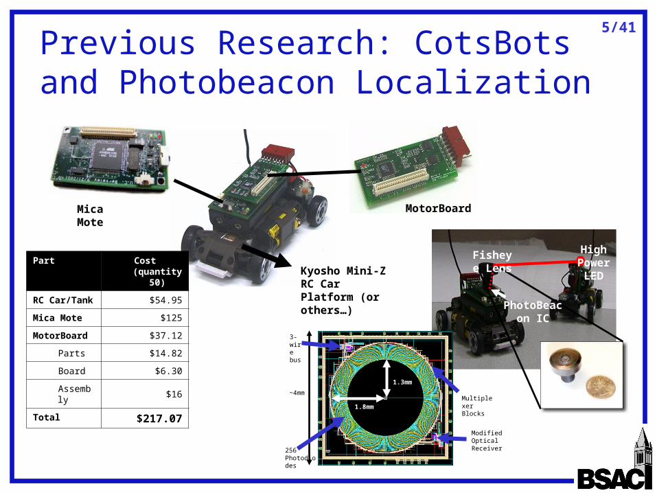
Previous Research: CotsBots and Photobeacon Localization
Mica Mote MotorBoard
Kyosho Mini-Z RC Car Platform (or others…)
Part Cost (quantity 50)
RC Car/Tank $54.95
Mica Mote $125
MotorBoard $37.12
Parts $14.82
Board $6.30
Assembly $16
Total $217.07
Fisheye Lens
High Power LED
PhotoBeacon IC
~4mm
256 Photodiodes
Multiplexer Blocks
3-wire bus
Modified Optical Receiver
1.3mm
1.8mm
6/41
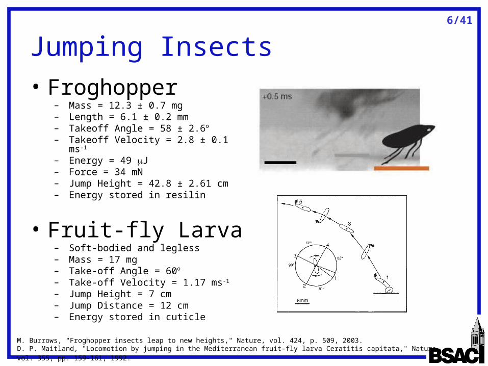
Jumping Insects• Froghopper
– Mass = 12.3 ± 0.7 mg– Length = 6.1 ± 0.2 mm– Takeoff Angle = 58 ± 2.6o
– Takeoff Velocity = 2.8 ± 0.1 ms-1
– Energy = 49 J – Force = 34 mN– Jump Height = 42.8 ± 2.61 cm– Energy stored in resilin
• Fruit-fly Larva– Soft-bodied and legless– Mass = 17 mg– Take-off Angle = 60o
– Take-off Velocity = 1.17 ms-1
– Jump Height = 7 cm– Jump Distance = 12 cm– Energy stored in cuticle
M. Burrows, "Froghopper insects leap to new heights," Nature, vol. 424, p. 509, 2003.
D. P. Maitland, "Locomotion by jumping in the Mediterranean fruit-fly larva Ceratitis capitata," Nature, vol. 355, pp. 159-161, 1992.
7/41
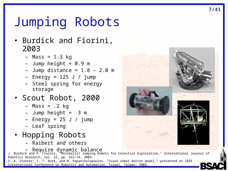
Jumping Robots• Burdick and Fiorini, 2003
– Mass = 1.3 kg– Jump height = 0.9 m– Jump distance = 1.8 – 2.0 m– Energy = 125 J / jump– Steel spring for energy storage
• Scout Robot, 2000– Mass = .2 kg– Jump height = .3 m– Energy = 25 J / jump– Leaf spring
• Hopping Robots– Raibert and others– Require dynamic balance
J. Burdick and P. Fiorini, "Minimalist Jumping Robots for Celestial Exploration," International Journal of Robotics Research, vol. 22, pp. 653-74, 2003.S. A. Stoeter, I. T. Burt, and N. Papanikolopoulos, "Scout robot motion model," presented at IEEE International Conference on Robotics and Automation, Taipei, Taiwan, 2003.
8/41
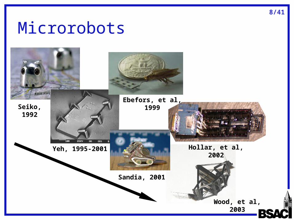
Wood, et al, 2003
Microrobots
Seiko, 1992
Yeh, 1995-2001 Hollar, et al, 2002
Ebefors, et al, 1999
Sandia, 2001

9/41
Overview
• Motivation and Previous Work• Jumping for Microrobot Locomotion• Robot Design
– Actuation– Energy Storage– Power – Control
• Fabrication and Integration

10/41
Jumping: Trajectory
• Muscle/motor work kinetic energy for jump
• How high?
• How far?
• Can use to jump over obstacles
mghvm 2sin5.0
cossin2 vgvd
0 10 20 30 40 50-10
-5
0
5
10
15
20
25
30
35
Hopping Trajectory, Mass = 15 mg, Angle = 60 deg
distance (cm)
heig
ht (
cm)
5 uJ10 uJ25 uJ50 uJ
heig
ht (
cm)
distance (cm)
Hopping Trajectory, Mass = 15mg, Angle = 60deg
11/41
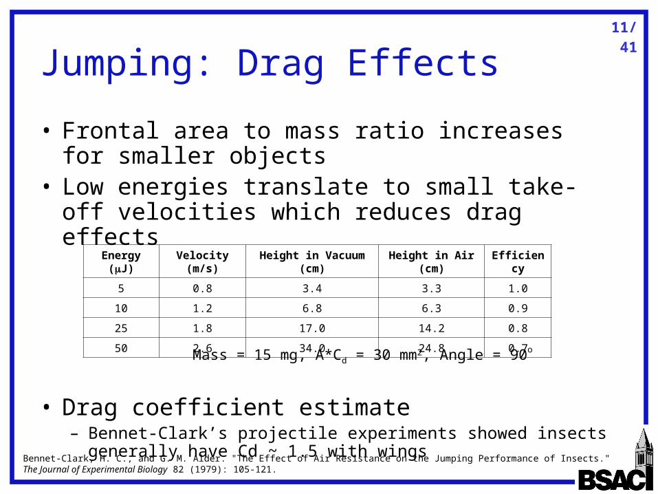
Jumping: Drag Effects
• Frontal area to mass ratio increases for smaller objects
• Low energies translate to small take-off velocities which reduces drag effects
• Drag coefficient estimate– Bennet-Clark’s projectile experiments showed insects
generally have Cd ~ 1.5 with wingsBennet-Clark, H. C., and G. M. Alder. "The Effect of Air Resistance on the Jumping Performance of Insects." The Journal of Experimental Biology 82 (1979): 105-121.
Mass = 15 mg, A*Cd = 30 mm2, Angle = 90o
Energy (J) Velocity (m/s) Height in Vacuum (cm) Height in Air (cm) Efficiency
5 0.8 3.4 3.3 1.0
10 1.2 6.8 6.3 0.9
25 1.8 17.0 14.2 0.8
50 2.6 34.0 24.8 0.7
12/41
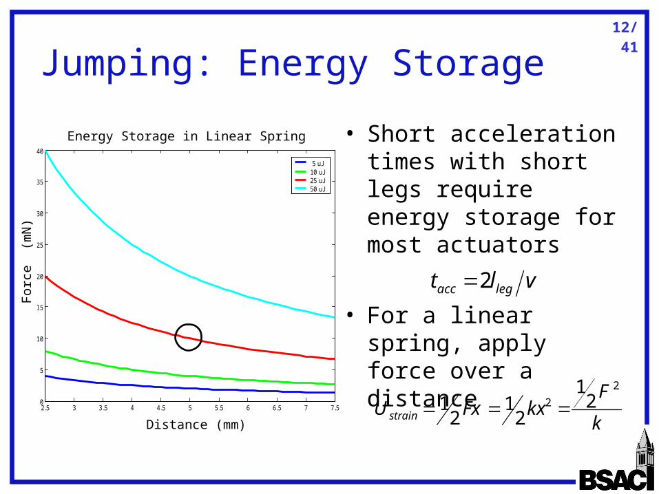
Jumping: Energy Storage
• Short acceleration times with short legs require energy storage for most actuators
• For a linear spring, apply force over a distance
vlt legacc 2
k
FkxFxU strain
2
2 21
21
21 2.5 3 3.5 4 4.5 5 5.5 6 6.5 7 7.5
0
5
10
15
20
25
30
35
40Force v. Distance
distance (mm)
forc
e (m
N)
5 uJ10 uJ25 uJ50 uJ
For
ce
(mN
)
Distance (mm)
Energy Storage in Linear Spring

13/41
Jumping: Energy Release
• Kinetic energy realized by leg release
• Assuming a linear spring in tension
• Burdick and Fiorini reported seeing early lift-off which reduced the kinetic energy delivered to robot by spring
offt
t hR dtVFE0
)cos(1)( wtltx eff
k
mglleff )2cos(1
4)(
2
wtkl
tE eff
0 0.5 1 1.5 2 2.5 3 3.5 4 4.50
5
10
15
20
25Kinetic Energy v. Time, m = 15mg, k = 2 N/m
Time (msec)
Kin
etic
Ene
rgy
(uJ)
Ene
rgy
(J)
Time (msec)
Kinetic Energy v. Time, Mass = 15mg, k = 2 N/m
14/41
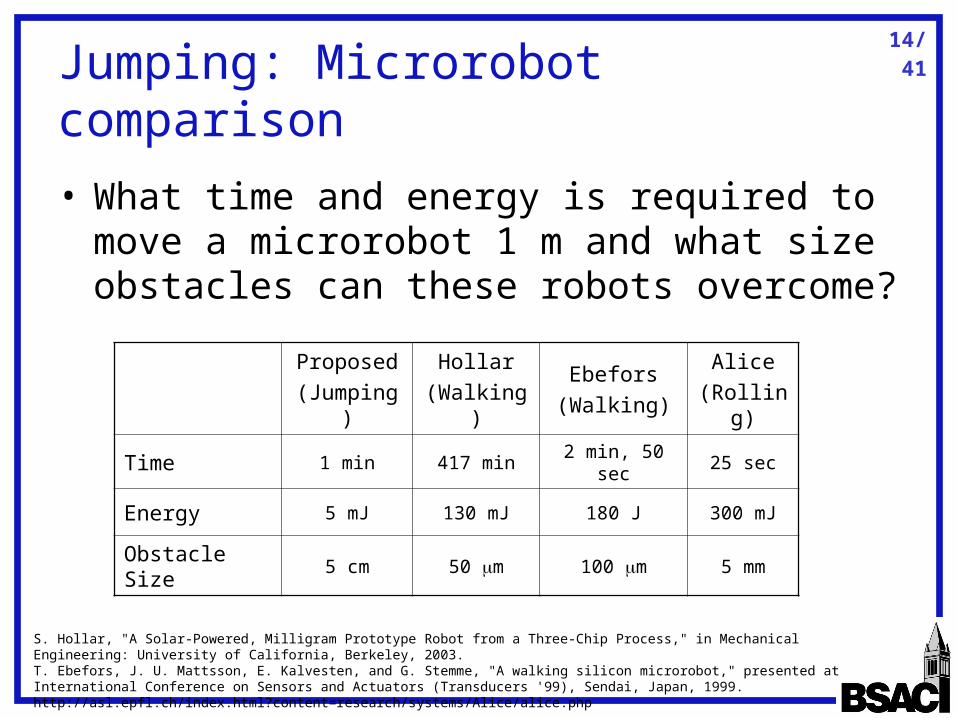
Jumping: Microrobot comparison
• What time and energy is required to move a microrobot 1 m and what size obstacles can these robots overcome?
Proposed (Jumping)
Hollar(Walking)
Ebefors(Walking)
Alice(Rolling)
Time 1 min 417 min 2 min, 50 sec 25 sec
Energy 5 mJ 130 mJ 180 J 300 mJ
Obstacle Size 5 cm 50 m 100 m 5 mm
S. Hollar, "A Solar-Powered, Milligram Prototype Robot from a Three-Chip Process," in Mechanical Engineering: University of California, Berkeley, 2003. T. Ebefors, J. U. Mattsson, E. Kalvesten, and G. Stemme, "A walking silicon microrobot," presented at International Conference on Sensors and Actuators (Transducers '99), Sendai, Japan, 1999. http://asl.epfl.ch/index.html?content=research/systems/Alice/alice.php
15/41
Overview
• Motivation and Previous Work• Jumping for Locomotion• Robot Design
– Actuation– Energy Storage– Power – Control
• Fabrication and Integration

16/41
• High force, long stroke motor
• Spring for energy storage
• Power for motors and control
• Control to direct motors
• Landing and resetting for next jump are NOT discussed
Robot Design Requirements
17/41
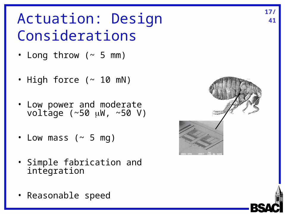
Actuation: Design Considerations
• Long throw (~ 5 mm)
• High force (~ 10 mN)
• Low power and moderate voltage (~50 W, ~50 V)
• Low mass (~ 5 mg)
• Simple fabrication and integration
• Reasonable speed
18/41
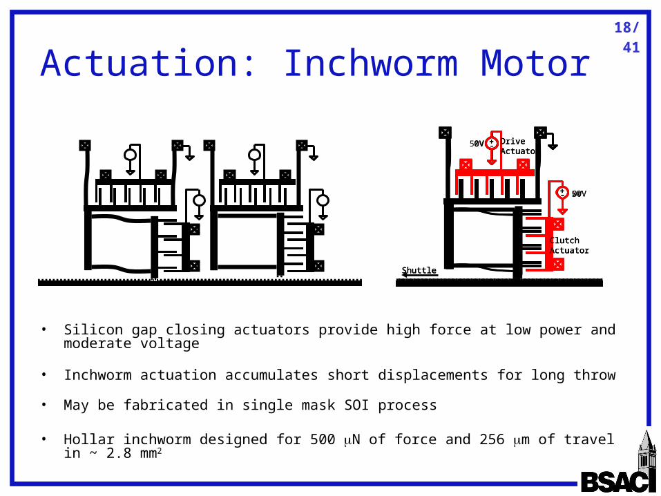
Actuation: Inchworm Motor
• Silicon gap closing actuators provide high force at low power and moderate voltage
• Inchworm actuation accumulates short displacements for long throw
• May be fabricated in single mask SOI process
• Hollar inchworm designed for 500 N of force and 256 m of travel in ~ 2.8 mm2
+-0V
0V
ClutchActuator
DriveActuator
Shuttle
+-
+-0V
50V
ClutchActuator
DriveActuator
Shuttle
+-
+-50V
50V
ClutchActuator
DriveActuator
Shuttle
+-
19/41
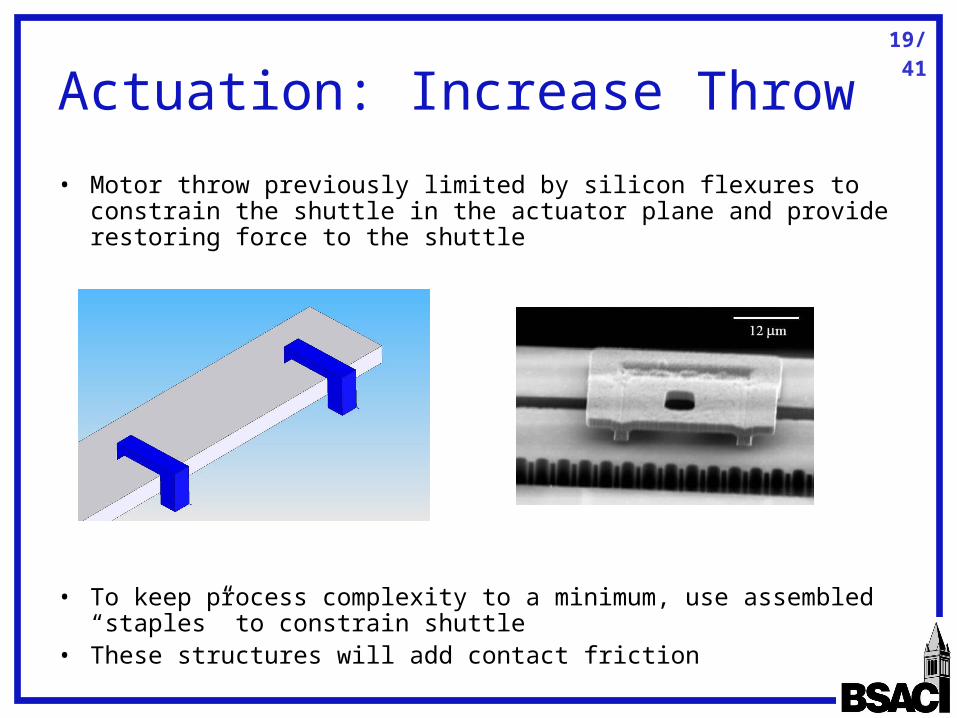
Actuation: Increase Throw
• Motor throw previously limited by silicon flexures to constrain the shuttle in the actuator plane and provide restoring force to the shuttle
• To keep process complexity to a minimum, use assembled “staples” to constrain shuttle
• These structures will add contact friction
20/41
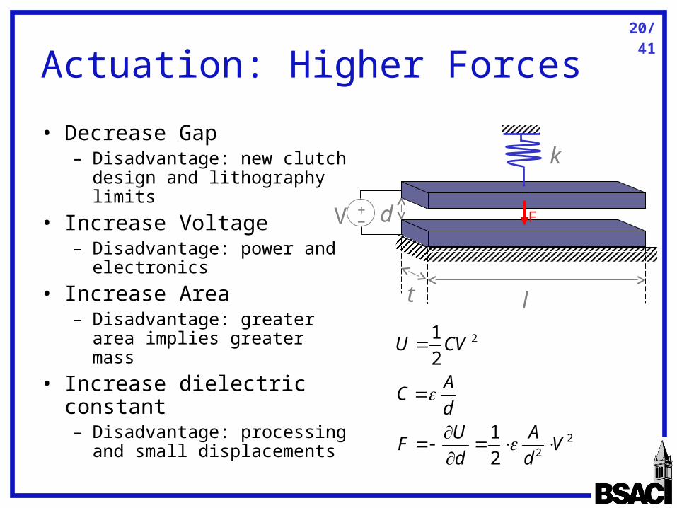
Actuation: Higher Forces
• Decrease Gap– Disadvantage: new clutch
design and lithography limits
• Increase Voltage– Disadvantage: power and
electronics
• Increase Area– Disadvantage: greater
area implies greater mass
• Increase dielectric constant– Disadvantage: processing
and small displacements
l
+-V d
t
k
F
22
2
2
1
2
1
Vd
A
d
UF
d
AC
CVU
21/41
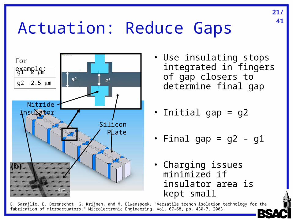
Actuation: Reduce Gaps
• Use insulating stops integrated in fingers of gap closers to determine final gap
• Initial gap = g2
• Final gap = g2 – g1
• Charging issues minimized if insulator area is kept small
g1g2
E. Sarajlic, E. Berenschot, G. Krijnen, and M. Elwenspoek, "Versatile trench isolation technology for the fabrication of microactuators," Microlectronic Engineering, vol. 67-68, pp. 430-7, 2003.
For example:
g1 2 m
g2 2.5 m
Nitride Insulator
Silicon Plate
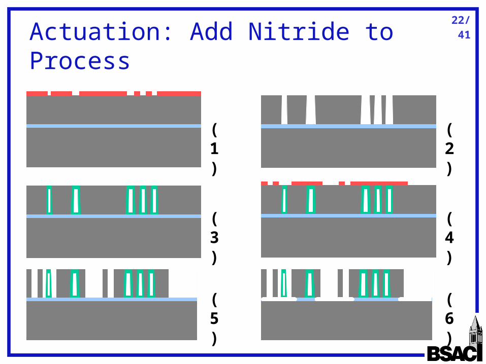
22/41
Actuation: Add Nitride to Process
(1) (2)
(3) (4)
(5) (6)

23/41
Actuation: Reduce Initial Gap• Drive force dependent on initial gap of the drive actuator• Add a transmission to reduce initial gap beyond lithographic limits• Provide an additional mechanical stop to limit return motion of
drive frame• Force required minimized to just the restoring force of springs on
drive frame• Reduces force density of actuator, but effect minimal
+-0V Drive
Actuator
+-0V
TransmissionActuator
+-50V Drive
Actuator
+-0V
TransmissionActuator
+-50V Drive
Actuator
+-50V
TransmissionActuator
+-0V Drive
Actuator
+-50V
TransmissionActuator
gnew
24/41
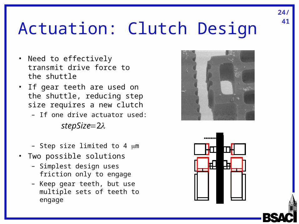
Actuation: Clutch Design
• Need to effectively transmit drive force to the shuttle
• If gear teeth are used on the shuttle, reducing step size requires a new clutch– If one drive actuator used:
– Step size limited to 4 m
• Two possible solutions– Simplest design uses
friction only to engage– Keep gear teeth, but use
multiple sets of teeth to engage
2stepSize
25/41
Actuation: Friction Clutch Design
• High force required to prevent slipping
• Clutch force dependent on final gap which reduces area requirements
• Tas, et al. estimated the friction coefficient of this clamp/shuttle interaction at = 0.8 ± 0.3 – Stepper motor in single mask 5 m polysilicon– 2 m steps, 15 m deflection at 3 N limited by flexures
used– Adhesion found low enough to release clamp
N. R. Tas, A. H. Sonnenberg, A. F. M. Sander, and M. C. Elwenspoek, "Surface micromachined linear electrostatic stepper motor," presented at IEEE Tenth Annual International Workshop on Micro Electro Mechanical Systems, New York, NY, 1997.
26/41
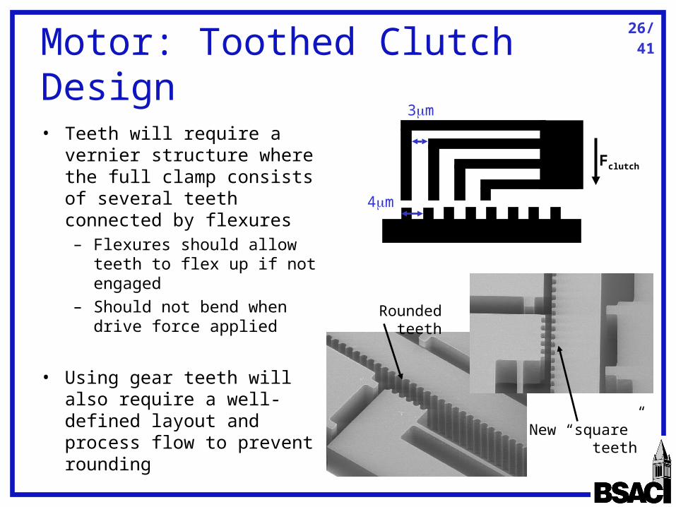
Motor: Toothed Clutch Design
• Teeth will require a vernier structure where the full clamp consists of several teeth connected by flexures– Flexures should allow
teeth to flex up if not engaged
– Should not bend when drive force applied
• Using gear teeth will also require a well-defined layout and process flow to prevent rounding
Rounded teeth
New “square” teeth
Fclutch
3m
4m
27/41
0.5 0.6 0.7 0.8 0.9 1 1.1 1.2 1.3 1.4 1.50
1
2
3
4
5
6
Gap in microns
Are
a in
mm
-squ
ared
Area v. gap for F=0.01 N
30 V50 V80 V
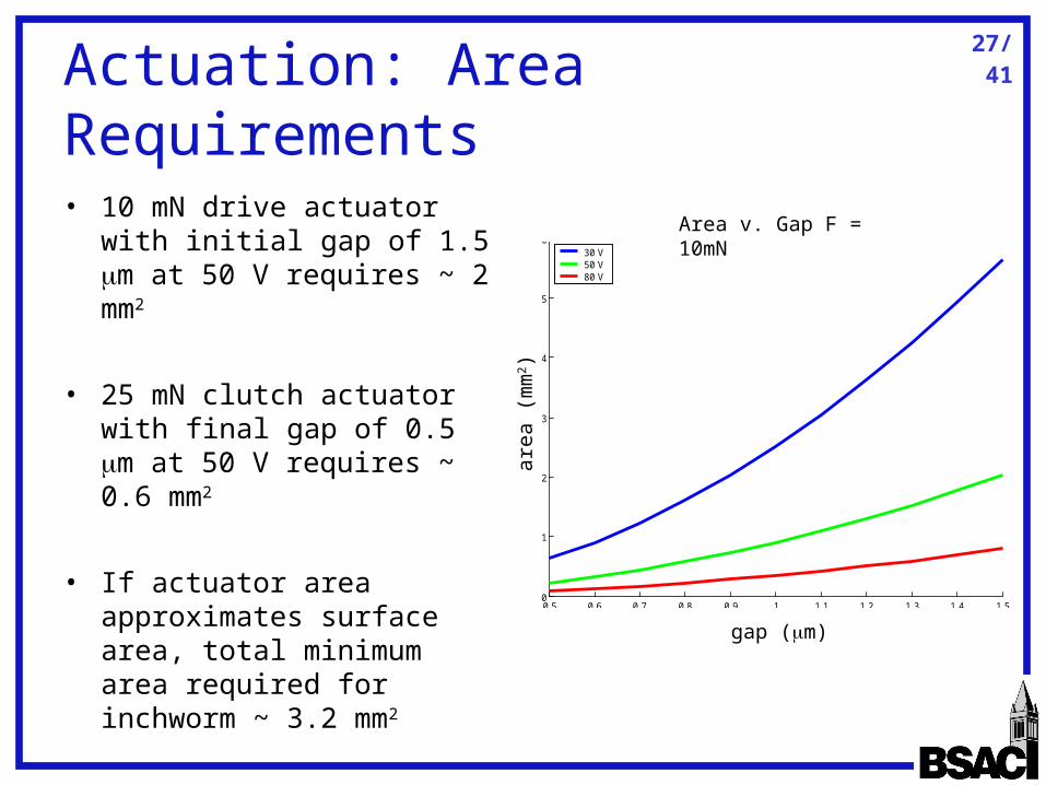
Actuation: Area Requirements
• 10 mN drive actuator with initial gap of 1.5 m at 50 V requires ~ 2 mm2
• 25 mN clutch actuator with final gap of 0.5 m at 50 V requires ~ 0.6 mm2
• If actuator area approximates surface area, total minimum area required for inchworm ~ 3.2 mm2
area
(m
m2)
gap (m)
Area v. Gap F = 10mN
28/41
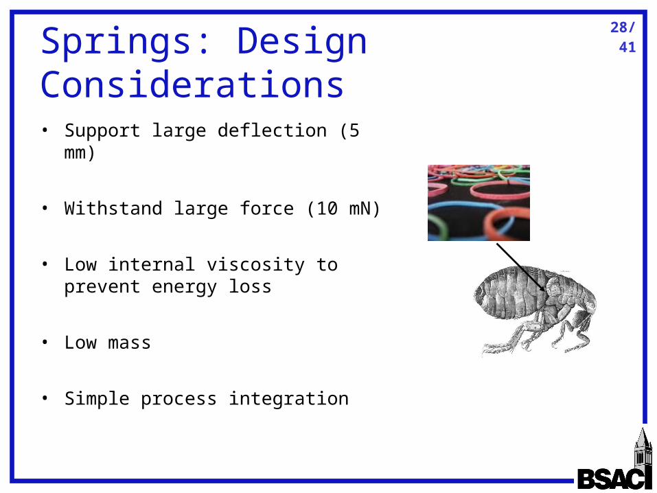
Springs: Design Considerations
• Support large deflection (5 mm)
• Withstand large force (10 mN)
• Low internal viscosity to prevent energy loss
• Low mass
• Simple process integration

29/41
Springs: Materials
• Maximum distance traveled
• Maximum force which can be applied
• Energy stored
E
lx
max
Material E (Pa) Strength (Pa) Energy Density (mJ/mm3)
Si 1.6e11 3.2e9 2
Silicone 1e6 2.25e6 2.5
Polyimide 2e9 231e6 13.3
Parylene 2e9 69e6 1.2
Resilin 2e6 6e6 9AF max
E
lAxFU
2
maxmaxmax 21
21
A
For 5 mm travel at 10 mN
Si: l = 1 m, A = 12.5 m2
Polyimide: l = 43 mm, 43 m2
Silicone: l = 2.2 mm, A = 4400 m2
l
30/41
Springs: Fabrication
• Elastomers appear to be a good choice due to high strains available
• To fabricate micro rubber bands– Use thin elastomer materials already available
off-the-shelf (30 m thick latex-like material)– Could also spin on liquid elastomer material
(latex, silicone) to desired thickness– Use Nd:YAG laser to cut desired pattern in
elastomer– Assemble micro-band into silicon motor
M. Schuettler, S. Stiess, B. V. King, and G. J. Suaning, "Fabrication of implantable microelectrode arrays by laser cutting of silicone rubber and platinum foil," Journal of Neural Engineering, vol. 2, pp. 121-128, 2005.
31/41
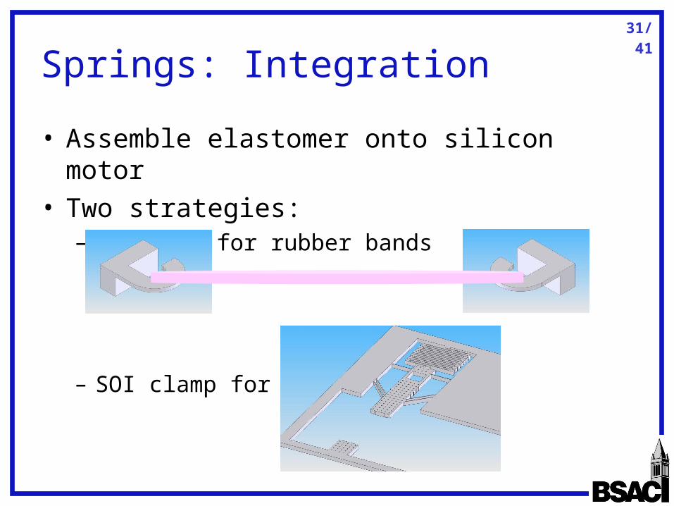
Springs: Integration
• Assemble elastomer onto silicon motor• Two strategies:
– SOI hook for rubber bands
– SOI clamp for rubber strips
32/41
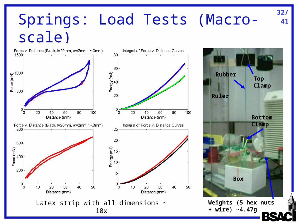
Springs: Load Tests (Macro-scale)
Top Clamp
Bottom Clamp
Box
Weights (5 hex nuts + wire) ~4.47g
Ruler
Rubber
Latex strip with all dimensions ~ 10x

33/41
Power: Design Considerations
• Provide power for multiple jumps
• Minimal additional circuitry to control actuators
• Small mass and area
• Simple integration to motors and control element
34/41
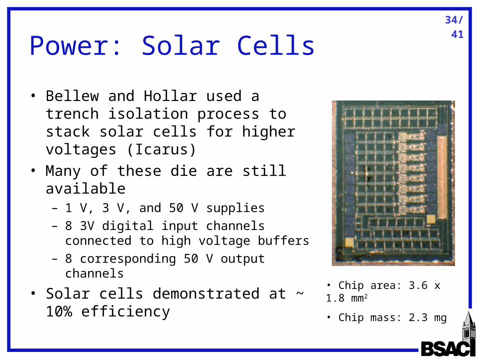
Power: Solar Cells
• Bellew and Hollar used a trench isolation process to stack solar cells for higher voltages (Icarus)
• Many of these die are still available– 1 V, 3 V, and 50 V supplies– 8 3V digital input channels
connected to high voltage buffers– 8 corresponding 50 V output
channels
• Solar cells demonstrated at ~ 10% efficiency
• Chip area: 3.6 x 1.8 mm2
• Chip mass: 2.3 mg
35/41
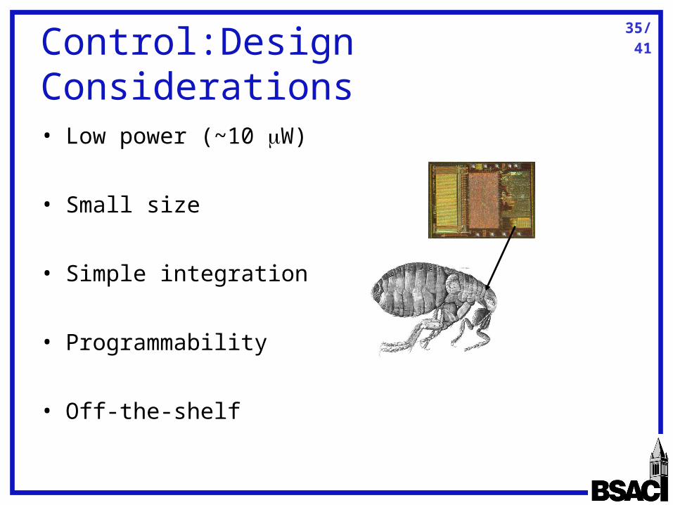
Control:Design Considerations
• Low power (~10 W)
• Small size
• Simple integration
• Programmability
• Off-the-shelf
36/41
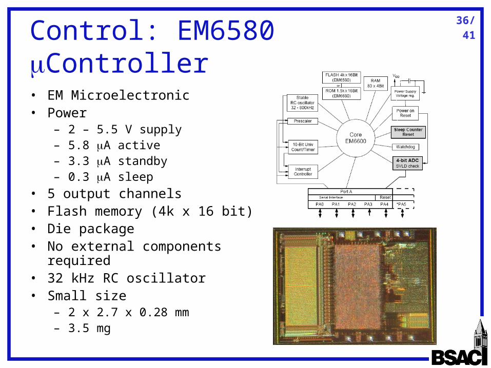
Control: EM6580 Controller
• EM Microelectronic• Power
– 2 – 5.5 V supply– 5.8 A active– 3.3 A standby– 0.3 A sleep
• 5 output channels• Flash memory (4k x 16 bit)• Die package• No external components
required• 32 kHz RC oscillator• Small size
– 2 x 2.7 x 0.28 mm– 3.5 mg

37/41
Overview
• Motivation and Previous Work• Jumping for Locomotion• Robot Design
– Actuation– Energy Storage– Power – Control
• Fabrication and Integration

38/41
Fabrication
• Add a 3rd mask to remove wafer backside and lighten the robot
• Use clamp techniques developed by Last and Subramaniam for assembly
• 3 mask + assembly process
M. Last, V. Subramaniam, and K. S. J. Pister, "Out of plane motion of assembled microstructures using a single-mask SOI process," presented at International Conference on Solid-State Sensors, Actuators and Microsystems, Seoul, Korea, 2005.
39/41
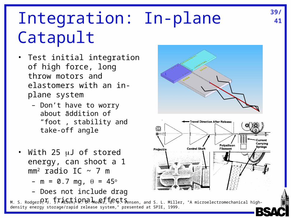
Integration: In-plane Catapult
• Test initial integration of high force, long throw motors and elastomers with an in-plane system– Don’t have to worry about
addition of “foot”, stability and take-off angle
• With 25 J of stored energy, can shoot a 1 mm2 radio IC ~ 7 m– m = 0.7 mg, = 45o
– Does not include drag or frictional effects
M. S. Rodgers, J. J. Allen, K. D. Meeks, B. D. Jensen, and S. L. Miller, "A microelectromechanical high-density energy storage/rapid release system," presented at SPIE, 1999.

40/41
Integration: Full Robot
Solar Cells EM6580
Shuttle, Springs, and Motor
Wire bonding Mass (mg) Dimensions (mm) Power (W)
Motors @ 500 Hz 8.8 4 x 8 x 0.3 30
Spring - 2.5 x .03 x .05 0
Solar Cells + High Voltage Buffers
2.3 3.6 x 1.8 x 0.15 100
EM6580 Controller 3.5 2 x 2.7 x 0.28 11.6
Total Robot 14.6 4 x 8 x 0.6 58.4
41/41
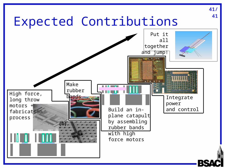
Expected Contributions
High force, long throw motors + fabrication process
Make rubber bands
Build an in-plane catapult by assembling rubber bands with high force motors
Integrate power and control
Put it all together and
jump!

Backup Slides

43/41
Jumping: Physics 101
• Kinetic energy (Work done to jump)
• Based on takeoff angle, break up velocity into vertical and horizontal components
• Find height achieved with this velocity
• Time in downward trajectory
• Lateral distance traveled
2
2mvKE
cos
sin
vv
vv
horizontal
vertical
mghvm
2
)sin( 2g
vh
2
)sin( 2
2
2gth g
vt
sin
g
vv
g
vd
2sincos
sin2
2

44/41
Jumping: Drag Effects
• With air resistance as a factor, there will be an optimal mass for the robot– If mass is small, drag
forces increase
– If mass is large, gravitational forces increase
• A mass of several mg would be best for these energies
0 2 4 6 8 10 12 14 16 18 200
5
10
15
20
25Height v. Mass
mass (mg)
heig
ht (
cm)
5 uJ10 uJ25 uJ50 uJ
heig
ht (
cm)
Mass (mg)
Height v. Mass at 60o
m
KEACF drag
drag
45/41
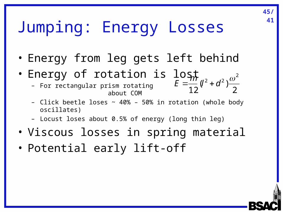
Jumping: Energy Losses
• Energy from leg gets left behind• Energy of rotation is lost
– For rectangular prism rotating about COM
– Click beetle loses ~ 40% – 50% in rotation (whole body oscillates)– Locust loses about 0.5% of energy (long thin leg)
• Viscous losses in spring material• Potential early lift-off
2)(
12
222
dlm
E
46/41
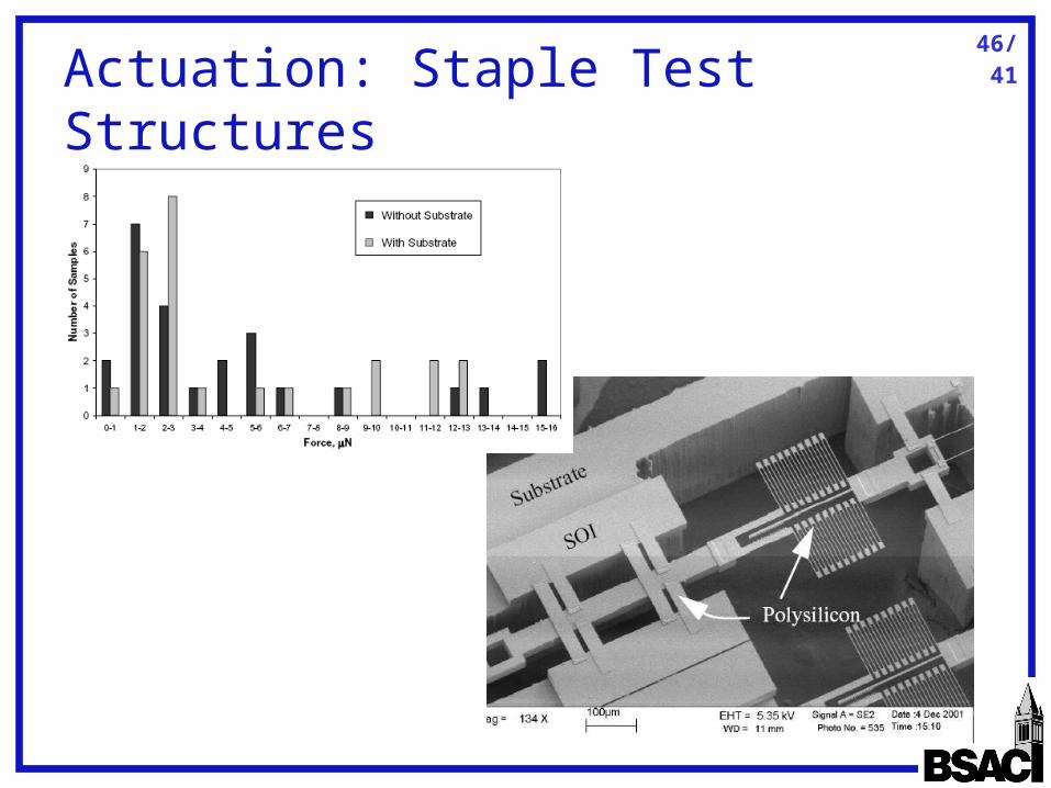
Actuation: Staple Test Structures
47/41
Actuation: Charge Accumulation
• Three causes of charge accumulation– Contact electrification (identical materials
should reduce this)– Breakdown (static and other factors)– RC charging from very small currents resulting
from electric field across the insulator
• Shrinking insulating area recommended to reduce extra charge from breakdown and RC effects
K. M. Anderson and J. E. Colgate, "A model of the attachment/detachment cycle of electrostatic micro actuators," presented at ASME Micromechanical Sensors, Actuators, and Systems, DSC-vol 32, Atlanta, GA, 1991. J. Wibbeler, G. Pfeifer, and M. Hietschold, "Parasitic charging of dielectric surfaces in capacitive microelectromechanical systems (MEMS)," Sensors & Actuators A-Physical, vol. 71, pp. 74-80, 1998.
48/41
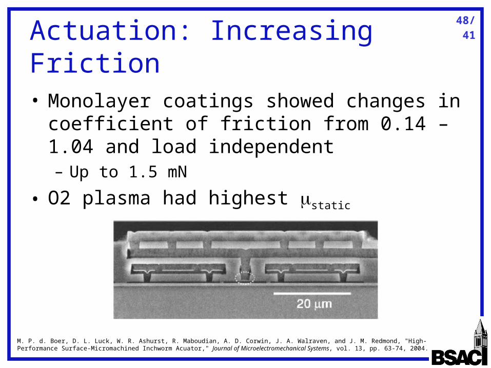
Actuation: Increasing Friction
• Monolayer coatings showed changes in coefficient of friction from 0.14 – 1.04 and load independent– Up to 1.5 mN
• O2 plasma had highest static
M. P. d. Boer, D. L. Luck, W. R. Ashurst, R. Maboudian, A. D. Corwin, J. A. Walraven, and J. M. Redmond, "High-Performance Surface-Micromachined Inchworm Acuator," Journal of Microelectromechanical Systems, vol. 13, pp. 63-74, 2004.
49/41
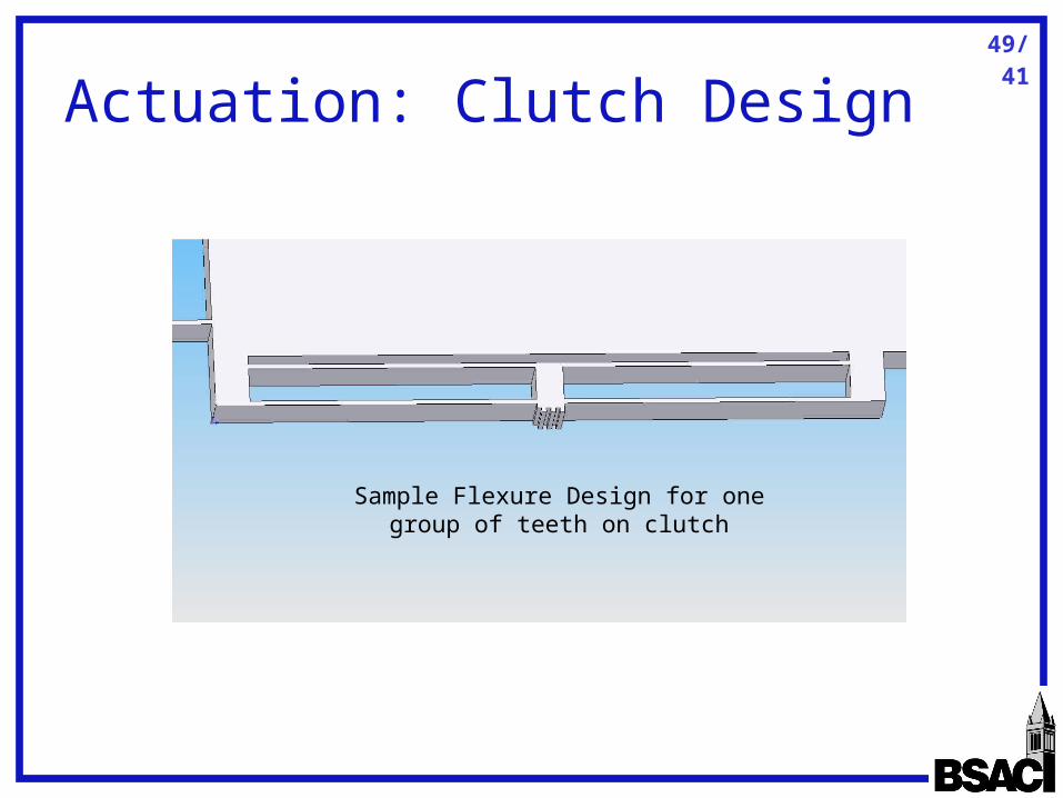
Actuation: Clutch Design
Sample Flexure Design for one group of teeth on clutch
50/41
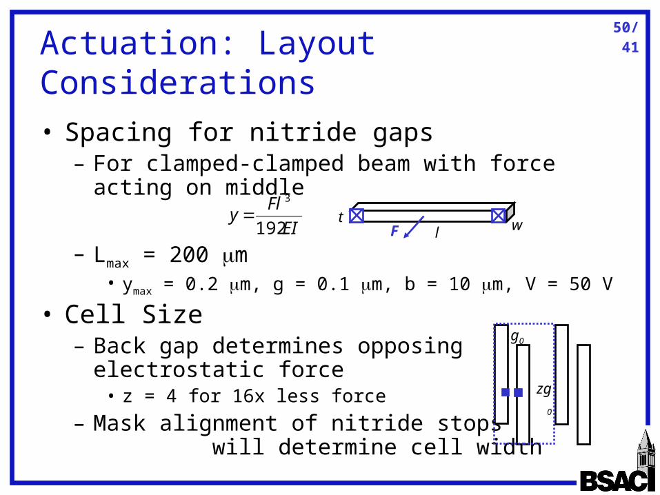
Actuation: Layout Considerations
• Spacing for nitride gaps– For clamped-clamped beam with force acting
on middle
– Lmax = 200 m • ymax = 0.2 m, g = 0.1 m, b = 10 m, V = 50 V
• Cell Size– Back gap determines opposing
electrostatic force• z = 4 for 16x less force
– Mask alignment of nitride stops will determine cell width
EI
Fly
192
3
l
t wF
g0
zg0
51/41
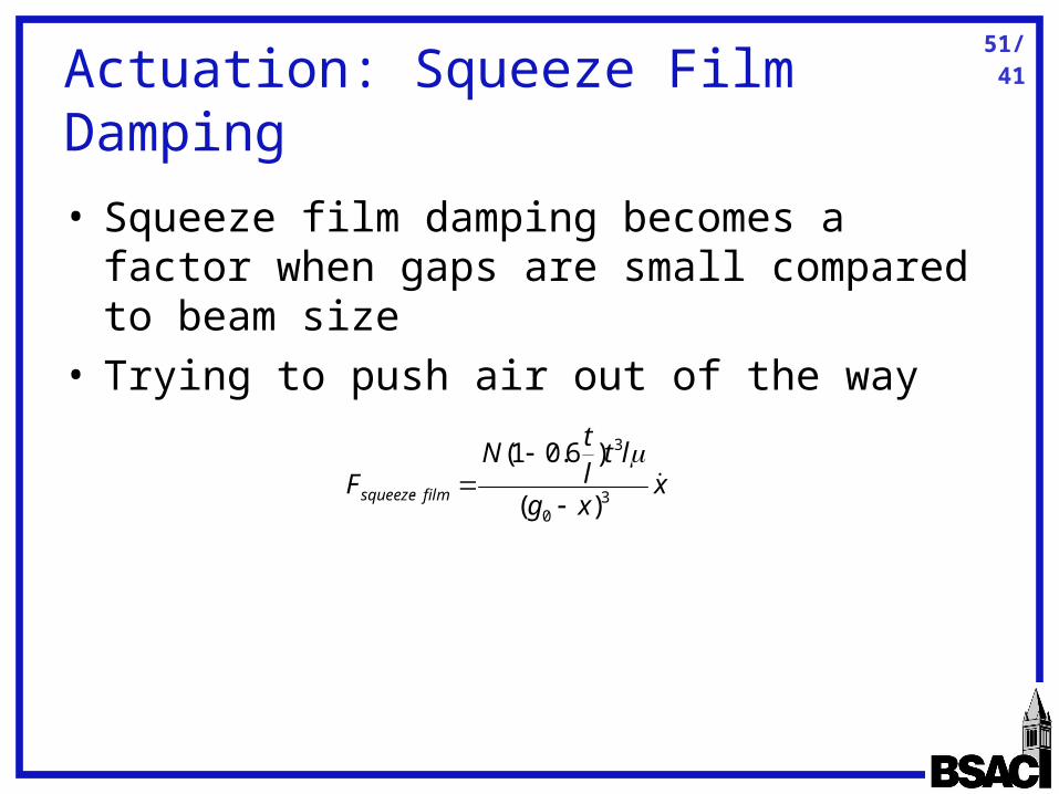
Actuation: Squeeze Film Damping
• Squeeze film damping becomes a factor when gaps are small compared to beam size
• Trying to push air out of the way
xxg
ltlt
NF filmsqueeze
30
3
)(
)6.01(

52/41
Springs: Examples in Biology
• Resilin is rubber-like – compliant but weak– Almost perfect cross-links (reduces viscosity)– Used in tension in dragonflies, but generally made short and fat
• Cuticle is strong and stiff– Crystalline– Often used in tension
H. C. Bennet-Clark, "Energy Storage in Jumping Insects," in The Insect Integument, H. R. Hepburn, Ed. Amsterdam: Elsevier Scientific Publishing Company, 1976, pp. 421-443.

53/41
Springs: Fabrication (Molding)
• Fabricate silicon mold• Place liquid elastomer on adhesive film
– Polyester film used
• Press die onto elastomer• Place in vacuum to remove bubbles• Cure at 100oC for 1 hour• Pry die off film
– No problems reported in removing PDMS from silicon die
J. I. Hout, J. Scheurer, and V. Casey, "Elastomer microspring arrays for biomedical sensors fabricated using micromachined silicon molds," Journal of Micromechanics and Microengineering, vol. 13, pp. 885-891, 2003.
54/41
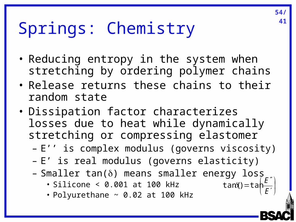
Springs: Chemistry
• Reducing entropy in the system when stretching by ordering polymer chains
• Release returns these chains to their random state
• Dissipation factor characterizes losses due to heat while dynamically stretching or compressing elastomer– E’’ is complex modulus (governs viscosity)– E’ is real modulus (governs elasticity)– Smaller tan() means smaller energy loss
• Silicone < 0.001 at 100 kHz• Polyurethane ~ 0.02 at 100 kHz
E
Etan)tan(
55/41
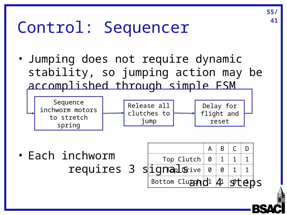
Control: Sequencer
• Jumping does not require dynamic stability, so jumping action may be accomplished through simple FSM
• Each inchworm requires 3 signals and 4 steps
Sequence inchworm motors to stretch spring
Release all clutches to jump
Delay for flight and reset
A B C D
Top Clutch 0 1 1 1
Top Drive 0 0 1 1
Bottom Clutch 1 1 0 1
56/41
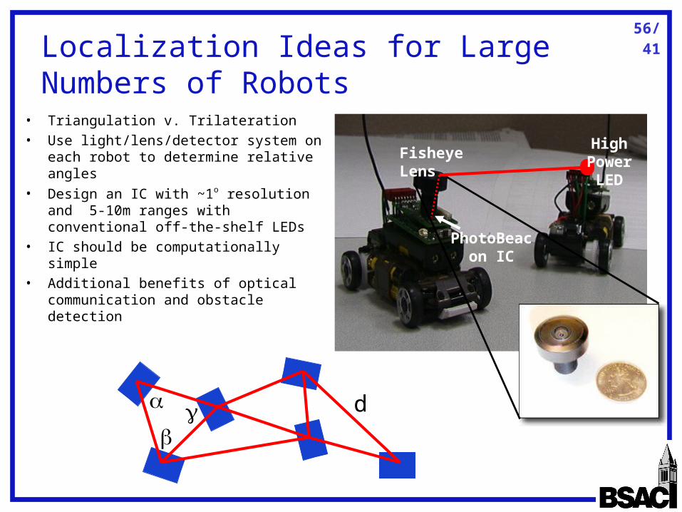
Localization Ideas for Large Numbers of Robots
Fisheye LensHigh Power
LED
PhotoBeacon IC
• Triangulation v. Trilateration• Use light/lens/detector system on
each robot to determine relative angles
• Design an IC with ~1o resolution and 5-10m ranges with conventional off-the-shelf LEDs
• IC should be computationally simple• Additional benefits of optical
communication and obstacle detection
d
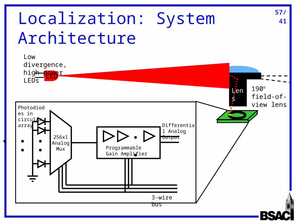
57/41Localization: System Architecture
256x1Analog
Mux
.....
..Programmable Gain Amplifier
Photodiodes in circular array
3-wire bus
Differential Analog Output
190o field-of-view lens
Lens
LED
Low divergence, high power LEDs
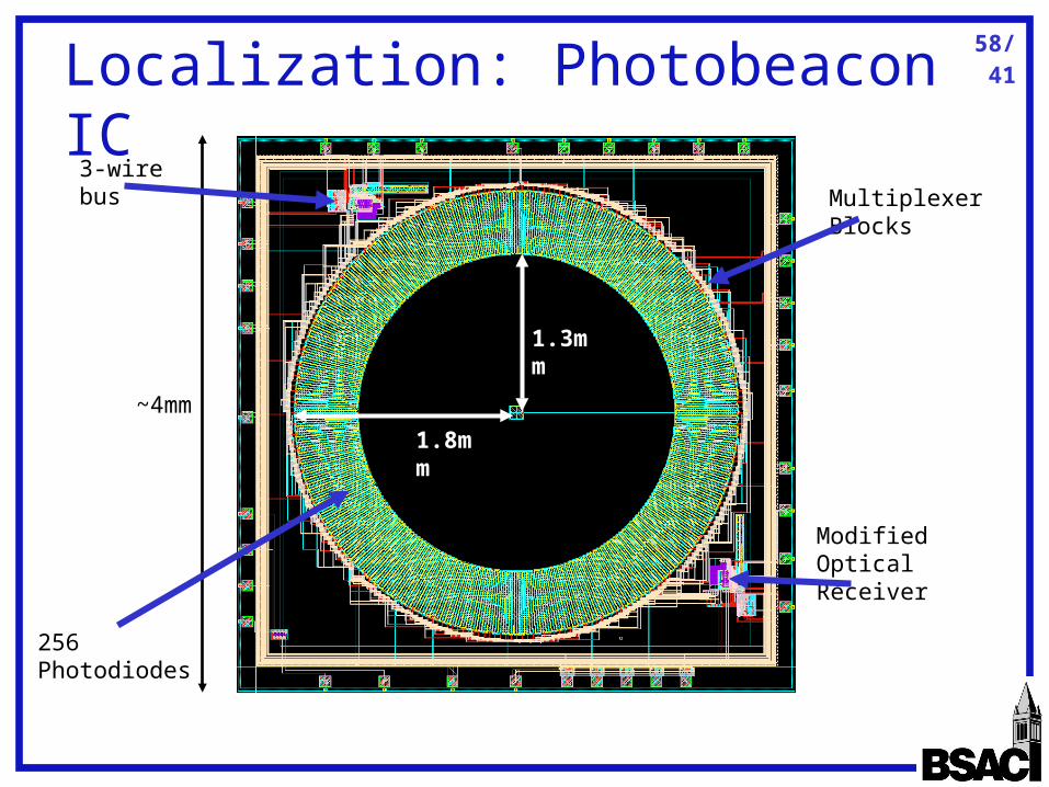
58/41
Localization: Photobeacon IC
~4mm
256 Photodiodes
Multiplexer Blocks3-wire bus
Modified Optical Receiver
1.3mm
1.8mm
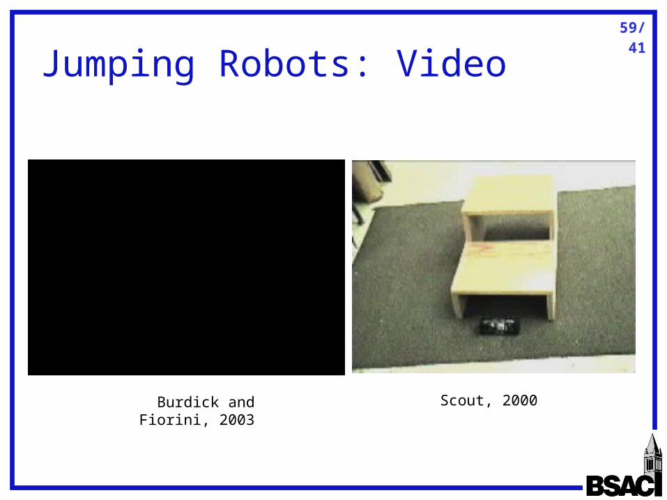
59/41
Jumping Robots: Video
Burdick and Fiorini, 2003 Scout, 2000