Embed Size (px)
Citation preview

Autonomous Navigation for Deep Space Missions
March 1, 2006
Presented by:Dr. Shyam Bhaskaran
Supervisor, Outer Planets Navigation Group
Jet Propulsion LaboratoryCalifornia Institute of Technology
This work was carried out at the Jet Propulsion Laboratory, California Institute of Technology, under a contract with the National Aeronautics and Space Administration.
March 1, 2006 ACGSC Meeting, March 1-3, 2006 SB-2
Agenda
• Ground based navigation• Why Autonomy?• Overview of Autonomous Optical Navigation
– Image Processing– Orbit Determination– Reduced State Encounter Navigation (RSEN)– AutoNav Interfaces with Spacecraft
• Mission Results– Deep Space 1– STARDUST– Deep Impact

March 1, 2006 ACGSC Meeting, March 1-3, 2006 SB-3
Ground-based Navigation
• Ground-based navigation uses 3 main data types– Radiometric data types (two-way range and Doppler) to get
spacecraft line-of-sight range and range-rate information from Deep Space Network tracking station
– Delta Differential One-way Range (DDOR) to get plane-of-sky angular position of s/c relative to known quasar
– Optical data from onboard camera to get target relative angular measurements, used on approach to target (primarily planetary satellites and small bodies)
• Tracking data obtained using 3 Deep Space Network complexes• All data processed on ground to compute orbit solution• Ground-based maneuvers computed and uplinked to spacecraft• Limited by light-time, turnaround time to compute and validate
solutions and maneuvers• Used successfully on missions to all planets (except Pluto),
several small bodies, for many mission types (orbiters, landers, etc.)

March 1, 2006 ACGSC Meeting, March 1-3, 2006 SB-4
Why Autonomy?• Reduce mission cost
– Tracking data involves use of Deep Space Network antennas • Limited resource• Cost directly related to amount of tracking time
– Operations personnel• The more people needed for ground operations, the higher the cost
• Increased science return– Round-trip light time to interplanetary spacecraft can be tens of
minutes to several hours• Decisions about sequencing of observations therefore cannot rely on
real-time data about spacecraft attitude and location
– Build in conservatism so that observations cover all possible cases, resulting in data which has no science information
– Use of onboard information can greatly improve ability to optimize science observations
March 1, 2006 ACGSC Meeting, March 1-3, 2006 SB-5
Why Not Autonomy?
• Limited computer resources onboard spacecraft• Maturity of onboard navigation systems still low
– Break-even point for cost vs. benefit not yet achieved– Limited decision making capability -- cannot react to
parameters beyond the design
• Inherent reluctance to relinquish control to onboard computer

March 1, 2006 ACGSC Meeting, March 1-3, 2006 SB-6
A Brief History of Autonomous Navigation used in Deep Space …
• Deep Space 1– 1st demonstration of fully autonomous onboard navigation– Cruise autonav used operationally until failure of onboard star
tracker– Flyby autotracking used successfully at encounter of comet Borrelly
• STARDUST– Encounter target tracking – Successful demo during flyby of asteroid Annefrank
• Deep Impact– Autonav successfully used by Impactor spacecraft to hit lit area of
comet as well as Flyby spacecraft to image impact site

March 1, 2006 ACGSC Meeting, March 1-3, 2006 SB-7
Autonomous Navigation Overview• Place certain computational elements of navigation onboard a
spacecraft so it can compute its own orbit and maneuvers to achieve desired target conditions
• Current version of autonav is based solely on optical data– Optical data is inherently easier to schedule and process
– Unlike radio data, does not require the use of DSN antennas
– Does not depend on Earth-based parameters which need to be updated
• Media calibrations• Earth orientation parameters
– Easier to detect anomalies
• Addition of camera hardware to spacecraft, if not already needed, difficult to justify
• Future versions will incorporate additional data types

March 1, 2006 ACGSC Meeting, March 1-3, 2006 SB-8
Autonomous Navigation Overview
• Key elements of autonomous navigation system– Image Processing
• Point source center-finding– Center of brightness– Multiple cross-correlation
• Extended Body center-finding– Center of brightness– “Blobber” (largest contiguous object) identifier
– Trajectory Numerical Integration• RK-7/8 N-body numerical integrator• Point-source gravity models• Solar pressure
– Orbit Determination• Iterating batch-sequential least-squares filter• Optical-only observables• Estimates s/c position, velocity, bias acceleration, solar pressure, s/c
attitude errors and rates
– Maneuver computations
March 1, 2006 ACGSC Meeting, March 1-3, 2006 SB-9
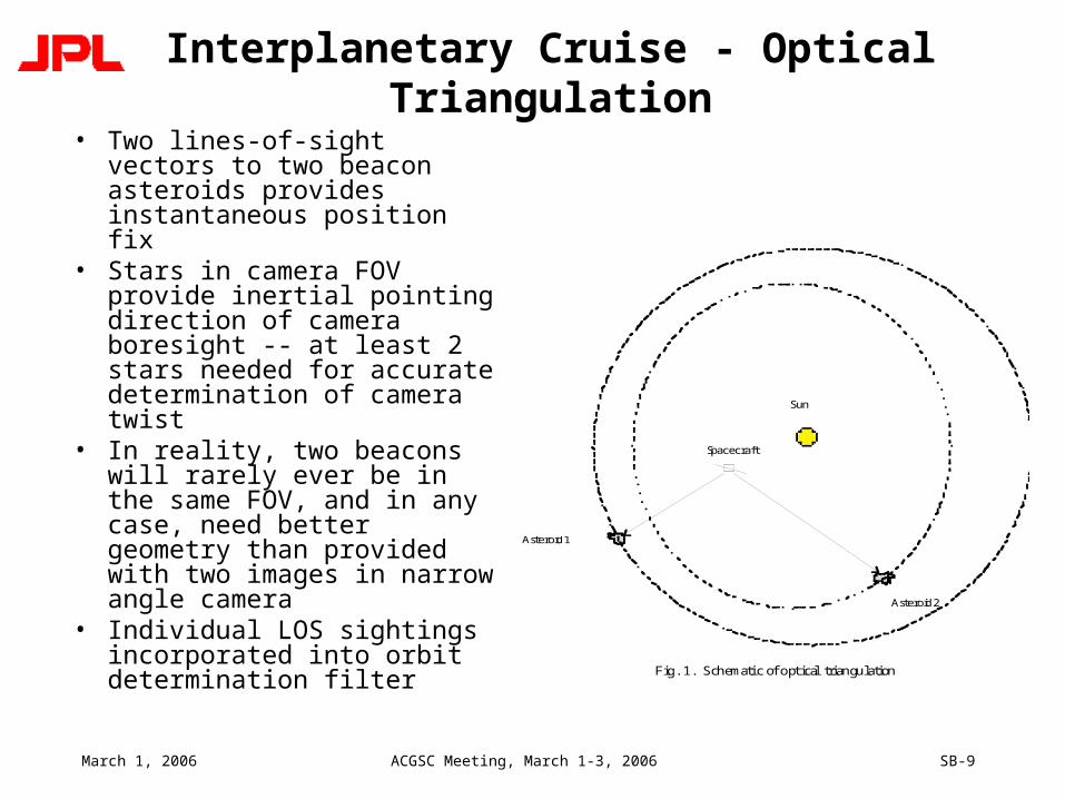
Interplanetary Cruise - Optical Triangulation
• Two lines-of-sight vectors to two beacon asteroids provides instantaneous position fix
• Stars in camera FOV provide inertial pointing direction of camera boresight -- at least 2 stars needed for accurate determination of camera twist
• In reality, two beacons will rarely ever be in the same FOV, and in any case, need better geometry than provided with two images in narrow angle camera
• Individual LOS sightings incorporated into orbit determination filter
Spacecraft
Asteroid 1
Asteroid 2
Sun
Fig. 1. Schemati c of opt ical triangulation

March 1, 2006 ACGSC Meeting, March 1-3, 2006 SB-10
Optical Triangulation
• Accuracy of triangulation method dependent on several factors:– Ability to determine exact centers of stars and object in FOV
(“centerfinding”)– Camera resolution– Distance from s/c to beacon object– Ephemeris knowledge of beacon object
• With given camera and centerfinding ability, angular accuracy of LOS fix is proportional to distance of beacons from s/c and knowledge of beacons ephemeris
• Asteroids make better beacon targets due to their proximity and number
• As target becomes nearer, it becomes sole beacon

March 1, 2006 ACGSC Meeting, March 1-3, 2006 SB-11
Flyby and/or Impact Navigation
• Target body becomes “extended” -- size greater than a pixel element
• Series of angular measurements of target computed by finding center-of-brightness or other region on target body
• Measurements combined in filter with a priori estimate of target relative position and velocity used to update target relative state to high accuracy
• Due to large difference in brightness between stars and target, image processing done in starless mode– Inertial camera pointing taken directly from IMU data, which
is not as good as using the stars– IMU bias and drift must be accounted for in filter to avoid
aliasing attitude effects with translational motion

March 1, 2006 ACGSC Meeting, March 1-3, 2006 SB-12
Orbit Determination
• Individual LOS fixes incorporated into filter to estimate complete s/c state– Position and velocity– Other parameters (solar radiation pressure, thruster mismodelling
accelerations, gas leaks, etc)• OD filter
– Linearization of dynamical equations of motion around reference trajectory
– Partial derivatives of observables (pixel/line centers of beacon in FOV) with respect to state parameters used to form information matrix
– Residual vector obtained from difference of observed beacon locations and predicts from reference trajectory
– Solution at epoch obtained using batch least-squares formulation to solve normal equations
• Dynamical equations of motion– Central body gravitation and 3rd body perturbations from planets– Solar radiation pressure and thruster accelerations– Integrated using Runge-Kutta 7-8 order integrator

March 1, 2006 ACGSC Meeting, March 1-3, 2006 SB-13
Maneuver Computation
• Based on OD results, map filtered solution to desired target conditions
• Determine miss distance from projected to desired target
• At predetermined times, compute velocity adjustment needed to achieve desired target
• Reconstruct achieved maneuver after execution using OD process
• OR…continuous control of thrust pointing vector for ion propulsion system (e.g. DS1)

March 1, 2006 ACGSC Meeting, March 1-3, 2006 SB-14
Autonomous Target Tracking
• During flyby, pace of events happening is much faster than during cruise• Quick turnaround OD solutions are needed to use late images of target
to update pointing control• Ground-based navigation solution not possible due to round-trip light
times• Reduced State Encounter Navigation (RSEN)
– Uses simplified, linear model of s/c flyby past comet.– Uses optical images as sole data type, with images starting about E-30
minutes at a rate of about 1 image every 30 seconds.– Initialized using final ground or onboard estimate of spacecraft state relative
to comet.– Observations accumulated for many minutes; 1st state update at about E-10
minutes. Subsequent state updates performed after every image acquisition.– Controls camera pointing only - no maneuvers performed to correct trajectory

March 1, 2006 ACGSC Meeting, March 1-3, 2006 SB-15
Autonav Interfaces with Spacecraft
• Autonav system needs to talk to rest of spacecraft– Point camera to take images, either by turning entire
spacecraft in case of fixed camera, or camera subsystem alone
– Implement and execute maneuvers– Disseminate orbit information to Attitude Control System– Receive attitude, thruster information from ACS
• Optimal to break out interface into real-time and non real-time sections– Real-time interface for high data rate information, such as
ephemeris server, thrust history data– Slower interface used for basic image processing, OD,
maneuver computation, and mini-sequence generation

March 1, 2006 ACGSC Meeting, March 1-3, 2006 SB-16
AutoNav Heritage Architecture
AutoNav Executive
Nav Real-Time Nav Main
OrbitDetermination
Maneuver,SEP Control
PicturePlanning andProcessing
EncounterOperations
EphemerisServer
Data-UpdateManagement
Non-GravHistory
Maintenance
Onboard-builtMicroSequence
SequencingSubsystem
(Main Sequence)
ACS
RCS
ImagingSubsystem
Fault-ProtectSubsystem
GimbalSubsystem
DS1 Heritage
DI Heritage
S/C Side
AutoNav Side

March 1, 2006 ACGSC Meeting, March 1-3, 2006 SB-17
Deep Space 1
• Background– DS1 was the first mission in NASA’s New Millennium Program - a
series of missions whose primary purpose is technology validation.– 12 new technologies validated during DS1’s prime mission. These
included:• Ion propulsion system• Autonomous optical navigation• Miniature Integrated Camera and Spectrometer (MICAS)• High power solar concentrator arrays (SCARLET)
• Mission timeline– Launched on October 24, 1998– Encounter with asteroid Braille on July 29, 1999 (completed primary
technology validation mission).• Demonstrated cruise autonav• Failed to track Braille during flyby.
– Due to grossly low signal from the APS camera channel (cause: inadequate camera calibration and extremely inopportune presentation geometry).
• Led to lessons learned for future flybys

March 1, 2006 ACGSC Meeting, March 1-3, 2006 SB-18
Deep Space 1
– Extended science mission to rendezvous with short period comets Wilson-Harrington and Borrelly approved.
– Sole onboard star tracker failed on November, 1999. • Spacecraft placed on extended safe-hold while new software
developed and tested to use MICAS camera as replacement for star tracker.
• Loss of thrust time resulted in inability to reach both targets, so Wilson-Harrington encounter was cancelled.
• Cruise autonav system relied on star tracker, so remainder of cruise used standard ground-based navigation
– New attitude control software using MICAS loaded and operational on June 2000. Thrusting resumes for Borrelly encounter.
– Borrelly encounter on September 23, 2001.• RSEN successfully tracked Borrelly for 2 hours through closest
approach

March 1, 2006 ACGSC Meeting, March 1-3, 2006 SB-19
Deep Space 1
• Encounter on September 22, 2001• Flyby velocity of 16.6 km/s, distance at closest
approach of 2100 km• RSEN initiated at E-32 minutes, based on ground-
based navigation information from E-12 hours– A priori position uncertainties of 350 km in Radial (or
equivalently, 21 seconds in time to encounter), 20 km in Transverse and Normal
– A priori gyro bias uncertainty of 0.1 deg, drift of 0.3 deg/hour
• Total of 52 images taken– 45 had Borrelly in camera FOV– Closest image taken at E-2 min, 46 seconds, at distance of
3514 km and resolution of 46 m/pixel
March 1, 2006 ACGSC Meeting, March 1-3, 2006 SB-20
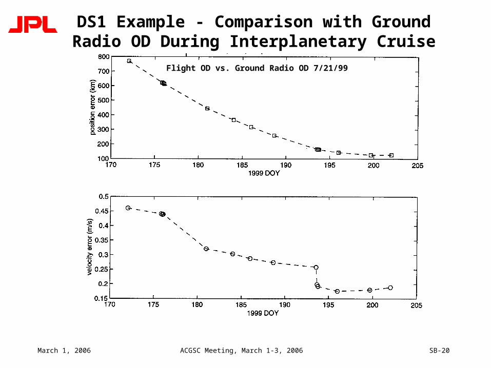
DS1 Example - Comparison with Ground Radio OD During Interplanetary Cruise
Flight OD vs. Ground Radio OD 7/21/99
March 1, 2006 ACGSC Meeting, March 1-3, 2006 SB-21
Deep Space 1

March 1, 2006 ACGSC Meeting, March 1-3, 2006 SB-22
Closest Image
• Image shuttered at E-2min, 13 sec.
• Distance of 3514 km.• Resolution of 40 m/pixel.

March 1, 2006 ACGSC Meeting, March 1-3, 2006 SB-23
STARDUST
• NASAs fourth Discovery Mission, following Mars Pathfinder, NEAR, Lunar Prospector
• Mission events:– Launch in February 7, 1998– Asteroid Annefrank flyby on November 2, 2003
• Dress rehearsal for actual encounter• Successfully tested RSEN tracking of asteroid
– Comet flyby on January 2, 2004 of the short period comet P/Wild-2. Flyby at comet relative velocity of 6.1 km/s
• Successful tracking of comet during flyby
– Earth return on January 15, 2006 with sample return capsule landing in Utah
• Primary science goal was to collect 500 particles of cometary dust greater than 15 micron size and return them to Earth
• Secondary science goal is to image the comet nucleus at a resolution of better than 40 m

March 1, 2006 ACGSC Meeting, March 1-3, 2006 SB-24
STARDUST
• Encounter on January 2, 2004• Flyby velocity of 6.12 km/s, closest approach at 237 km• RSEN initiated at E-30 minutes based on ground-based
information at E-48 hours– Opnav information from E-14 hours available, but state errors
considered to be of insufficient size to warrant additional command upload
– A priori RTN position uncertainties of 1100x20x20 km (time-to-encounter equivalent of 9 minutes)
– A priori gyro bias uncertainty of 0.1 deg
• 114 total images taken– All 114 images containing the comet in the FOV (72 total images
stored for downlink)– Closest image taken at E-4 seconds at distance of 239 km and
resolution of 14 m/pixel

March 1, 2006 ACGSC Meeting, March 1-3, 2006 SB-25
STARDUST

March 1, 2006 ACGSC Meeting, March 1-3, 2006 SB-26
Deep Impact
• NASA Discovery Mission• Mission timeline
– Launch on January 10, 2005– Comet impact on July 4, 2005
• Full autonav successfully used by Impactor to hit lit area on comet and Flyby spacecraft to image impact site
• Engineering Objectives– Impact comet Tempel 1 in an illuminated area– Track the impact site for 800 sec using the Flyby s/c imaging
instruments
• Science Objectives- Expose the nucleus interior material and study the composition- Understand the properties of the comet Tempel 1 nucleus via
observation of the ejecta plume expansion dynamics and crater formation characteristics

March 1, 2006 ACGSC Meeting, March 1-3, 2006 SB-27
Deep Impact
TCM-5 at E-30 hours
Tempel 1Nucleus
ShieldAttitude through
Inner ComaADCS aligns shield with relative velocity
Science and AutoNav Imaging to
Impact + 800 sec
ITM-1 E-90 min
ITM-2E-35 min
ITM-3E-12.5 min
Impactor ReleaseE-24 hours
AutoNav/ADCS ControlE-2 hr
Flyby S/CDeflection Maneuver
Release + 12 min(101 m/s)
2-wayS-band
Crosslink
500 km
Flyby S/C Science Data Playback
to 70-meter DSS
Flyby Science Real-Time Data
Flyby S/C Science And Impactor Data
64kbps
ADCS aligns ITSControl frame with
Relative velocityE-5 min
= 0.6 mrad
Impact!
Look-backImaging
E+45 min
Shield Attitude Entry

March 1, 2006 ACGSC Meeting, March 1-3, 2006 SB-28
Deep Impact - Impactor
• Impact on July 4, 2005 with impact velocity of 10.1 km/s• Full-up autonav system used• Autonav initiated at E-2 hr
– Acquire images of the comet nucleus every 15 sec– Perform trajectory determination updates (OD) every minute
starting 110 minutes before the expected time of impact
• Perform 3 primary Impactor targeting maneuvers– ITM-1 @ E-90 min, ITM-2 @ E-35 min, and ITM-3 @ E-12.5 min
• Acquire 3 images for Scene Analysis (SA) based offset @ E-16.5 min
• Use SA offset for computation of final targeting maneuver • Align the ITS boresight with the AutoNav estimated comet-
relative velocity vector starting @ E-5 min– Capture and transmit high-resolution images of the nucleus surface
surrounding predicted impact site

March 1, 2006 ACGSC Meeting, March 1-3, 2006 SB-29
Deep Impact - Impactor
QuickTime™ and aSorenson Video 3 decompressorare needed to see this picture.

March 1, 2006 ACGSC Meeting, March 1-3, 2006 SB-30
Deep Impact - Flyby
• Flyby velocity of 10.1 km/s at radius of 500 km• Autonav initiated at E-2 hours
– Acquire MRI images of the comet nucleus every 15 sec
– Perform trajectory determination updates every minute starting 110 minutes before the expected time of impact
– Produce and hold deltaTOI and deltaTOFI time updates with every OD
• Acquire 3 images for Scene Analysis (SA) based offset, relative to CB @ E-4 min
• Used SA offset to correct HRI control frame pointing• Align edge of Solar Array with the AutoNav-estimated comet-
relative velocity vector at shield mode entry– Shield mode defined to be when the estimated range is 700 km)

March 1, 2006 ACGSC Meeting, March 1-3, 2006 SB-31
Deep Impact - Flyby
QuickTime™ and aSorenson Video 3 decompressorare needed to see this picture.

March 1, 2006 ACGSC Meeting, March 1-3, 2006 SB-32
Future Enhancements
• Small-body orbit case– Requires pre-determined shape model to correlate observed
features with known features– Features can be limb/terminator or craters
• Planetary approach and capture– Use satellites of planets as beacons (e.g, Phobos and
Deimos for Mars)
• Entry, descent, and landing– Use correlation of surface features, combined with ranging
from Lidar
• Rendezvous– Track satellite for on-orbit rendezvous or capture