Embed Size (px)
Citation preview

Autonomous Shooting Gallery Robot
Project Design Report
DT04
Kyle Eckhart
Donald Fuldauer
Kevin Jones
Todd Marimon
Dr. Giakos
11/28/2011

ii
Table of Contents List of Figures .......................................................................................................... iii List of Tables ........................................................................................................... iv Abstract (Eckhart, Marimon) .................................................................................... 1 1. Problem Statement .............................................................................................. 2
Need ............................................................................................................................................ 2 Objective ..................................................................................................................................... 2 Research Survey .......................................................................................................................... 2 Marketing Requirements ............................................................................................................. 3 Objective Tree ............................................................................................................................. 4
2. Design Requirements Specification (Eckhart) ................................................... 5 3. Accepted Technical Design ................................................................................ 6
Hardware Level 0 (Fuldauer) ..................................................................................................... 6 Hardware Level 1(Fuldauer) ...................................................................................................... 8 Hardware Level 2 (Fuldauer) ................................................................................................... 12 Hardware Schematics (Fuldauer) ............................................................................................. 16 Software Level 0 (Eckhart, Marimon) ...................................................................................... 19 Software Level 1(Marimon) ...................................................................................................... 21 Software Flowcharts (Eckhart, Marimon) ................................................................................ 25 GUI Mock-up (Marimon) .......................................................................................................... 29 Targeting System (Eckhart, Jones, Marimon) .......................................................................... 30 Control System (Jones) ............................................................................................................. 32 Mechanical System (Jones) ....................................................................................................... 33 Design Considerations (Fuldauer, Jones) ................................................................................. 37
4. Parts List (Fuldauer, Jones) ............................................................................. 44 5. Material Budget Info (Eckhart) ........................................................................ 45 6. Project Schedules (Eckhart) ............................................................................. 46 7. Design Team Information ................................................................................. 48 8. Conclusions and Recommendations (Eckhart) ................................................ 49 9. References ........................................................................................................ 50 10. Appendices ....................................................................................................... 51

iii
List of Figures Figure 1 - Objective Tree ................................................................................................................ 4 Figure 2 - Hardware Level 0 Black Diagram .................................................................................. 6 Figure 3 - Hardware Level 1 Block Diagram ................................................................................. 8 Figure 4 - Hardware Level 2 Block Diagram ............................................................................... 12 Figure 5 - Gun Power Schematic .................................................................................................. 16 Figure 6 - Stepper Motor Drive Schematic ................................................................................... 17 Figure 7- Software Level 0 Block Diagram .................................................................................. 19 Figure 8 - Software Level 1 Block Diagram ................................................................................. 21 Figure 9 - Software Workflow Diagram ....................................................................................... 25 Figure 10 - Microcontroller Command Processing ...................................................................... 26 Figure 11 - Calibration Process Flowchart ................................................................................... 27 Figure 12 - GUI Mock-up ............................................................................................................. 29 Figure 13 - Control System Diagram ............................................................................................ 32 Figure 15 - 3-D Illustration of Mechanical System ...................................................................... 33 Figure 16 - Technical Drawings ................................................................................................... 34 Figure 17 - X-axis Stepper Motor and Worm Gear Linkage ........................................................ 35 Figure 18 - Y-axis Stepper Motor and Worm Gear Linkage ........................................................ 35 Figure 19 - Gun-Securing Wooden Insert ..................................................................................... 36 Figure 20 - Maximum distance and angle for movement in the y-axis ........................................ 37 Figure 21 - Maximum distance for any target .............................................................................. 38 Figure 22 - Smallest angular movement required for targeting .................................................... 38 Figure 23 - Worm gear system ...................................................................................................... 41 Figure 24 - In-rush current waveform for gun power ................................................................... 42

iv
List of Tables Table 1 - Hardware Level 0 Functional Requirement .................................................................... 7 Table 2- Hardware Level 1 - Power Supply FR ............................................................................. 9 Table 3 - Hardware Level 1 – Personal Computer AC Adapter FR ............................................... 9 Table 4 - Hardware Level 1 -Personal Computer FR ..................................................................... 9 Table 5 - Hardware Level 1 - Microcontroller FR ........................................................................ 10 Table 6 - Hardware Level 1 - Power Supply FR .......................................................................... 10 Table 7 - Hardware Level 1 - Camera FR ..................................................................................... 10 Table 8 - Hardware Level 1 - Firing Mechanism Control FR ...................................................... 11 Table 9- Hardware Level 1 - Firing Mechanism FR ..................................................................... 11 Table 10 - Hardware Level 1 - Stepper Motors FR ...................................................................... 11 Table 11 - Hardware Level 1 - Laser Emitter FR ......................................................................... 11 Table 12 - Hardware Level 2 - Power Supply FR ........................................................................ 13 Table 13 - Hardware Level 2 - Personal Computer AC Adapter FR ............................................ 13 Table 14 - Hardware Level 2 - Personal Computer FR ................................................................ 13 Table 15 - Hardware Level 2 - PIC Microcontroller FR .............................................................. 14 Table 16 - Hardware Level 2 - Camera FR ................................................................................... 14 Table 17 - Hardware Level 2 - Firing Mechanism Control FR .................................................... 14 Table 18 - Hardware Level 2 - Firing Mechanism FR .................................................................. 15 Table 19 - Hardware Level 2 - X-axis Stepper Motor FR ............................................................ 15 Table 20 - Hardware Level 2 - Y-axis Stepper Motor FR ............................................................ 15 Table 21 - Hardware Level 2 - Laser Emitter FR ......................................................................... 15 Table 22 - Software Level 0 FR .................................................................................................... 19 Table 23 - Software Level 1 - Image Enhancement and Processing FR ...................................... 21 Table 24 - Software Level 1 - Target Identification FR ............................................................... 22 Table 25 - Software Level 1 - Target Priority & Processing FR .................................................. 22 Table 26 - Software Level 1 - Firing Mechanism Motion Control FR ......................................... 22 Table 27 - Software Level 1 - Firing Control FR ......................................................................... 22 Table 28 - Software Level 1 - Manual Firing Mechanism Control FR ........................................ 23 Table 29- Parts List ....................................................................................................................... 44 Table 30 - Budget Table ............................................................................................................... 45

1
Abstract (Eckhart, Marimon) The RoboGames Shooting Gallery competition is a challenging competition in design and implementation of an autonomous robot that is able to shoot targets without human assistance. For this project, a robot to meet all the requirements of the competition will be designed and built within the time constraints of the project. This will be accomplished by utilizing optical sensors for targeting and a software piece that will interpret the optical images and determine how to position a firing mechanism to knock down the targets.
Key features:
• Targeting system is autonomous • Targeting system is easy to use • Targeting system is able to detect and prioritize white targets and ignore black targets • Targeting system is easily and quickly calibrated • Targeting system will ensure the targets are accurately and effectively removed from
sight • Robot has safety features to allow it to be quickly disabled • The firing mechanism utilizes safe projectiles • Robot has a power indicator to clearly indicate it is powered • The total project is lightweight

2
1. Problem Statement
Need
The Robotic Shooting Gallery competition will require the use of a target detection system to aid an autonomous aiming and firing mechanism to hit the targets. Although this concept has been previously implemented, there is always room for improving certain aspects of the robotic system. The need for incorporating a feedback system for aiming is such an improvement. There is a need for a system that can detect, aim, and fire a projectile as quickly as possible in order to compete effectively.
Objective
The objective of this project is to design and build a robotic aiming and firing system to the design specifications for the Robotic Shooting Gallery competition. The system will visually inspect a target line-up, aim at a target, and fire a safe projectile at thetarget as quickly as possible, scoring points for hitting the correct targets and losing points for hitting the incorrect targets. The robot will also operate without interaction by the operators.
Research Survey
The participant information regarding the Autonomous Shooting Gallery Robot competition held at RoboGames can be found through the organization web page [1].

3
Marketing Requirements
1. The system should have a clearly visible light indicating it is on. 2. The system should have a targeting mechanism that can position a firing
mechanism to aim with a certain accuracy within the bounds of a specific dimension.
3. The system should have a power system that distributes power between subsystems.
4. The system should fire a safe projectile. 5. The system should be equipped with a safety override switch to prevent undesired
operation. 6. The system should be able to quickly recognize white targets and avoid hitting
black targets. 7. The system should be able to prioritize targets based on the distance the gun will
need to travel to shoot the target 8. The system should be automatic and operate without assistance from the
operators. 9. The system should be as light as possible.

4
Objective Tree Figure 1 shows the objective tree that reflects the characteristics needed for a successful design and competition requirements that were given by RoboGames.
Autonomous Shooting
Gallery Robot
Targeting System Safety
Safety override switch
Visible power indicator
Safe Projectiles
Easy to Use Autonomous
Aim and fire
As fast as possible
Prioritize targets
Track moving objects
As light-weight as possible
Accurate
Calibration Procedure
Error Correction
Figure 1 - Objective Tree

5
2. Design Requirements Specification (Eckhart)
Marketing Requirements
Engineering Requirements Justification
1, 5 Must have a LED which will indicate the system has power and a switch which will remove power from
the gun
This is a safety precaution for any individual who is around the robot.
6, 7 Must be able to recognize and prioritize targets using a camera and an image recognition algorithm
The competition requires the use of only hardware and software to shoot
targets
8 Must require no human interaction after starting operations
The competition requires a completely autonomous device
9 Must weigh no more than 100 lbs. The lighter it is the easier it is to transport
4 Must fire a plastic Airsoft pellet The gun must fire a non-lethal projectile
2 Must be able to accurately aim given that the targets are 10’ away in a 5’x 5’ enclosure
These are the requirements for the targets in the competition
2 Must be able to aim at targets which range from ½” diameter to 3” diameter in size
These are the target sizes as dictated by the competition
3 Must be powered by 120V AC wall outlet It is a competition requirement that the power for the device will not be
flammable or solar.
2, 6, 8 Must be able to determine the airsoft gun is aiming directly at a white target and automatically make
adjustments accordingly.
The system needs to self-correcting in case the original movement calculation was incorrect.
1. The system should have a clearly visible light indicating it is on. 2. The system should have a targeting mechanism that can position a firing mechanism to aim with a
certain accuracy within the bounds of a specific dimension. 3. The system should have a power system that distributes power between subsystems. 4. The system should fire a safe projectile. 5. The system should be equipped with a safety override switch to prevent undesired operation. 6. The system should be able to quickly recognize white targets and avoid hitting black targets. 7. The system should be able to prioritize targets based on the distance the gun will need to travel to
shoot the target 8. The system should be automatic and operate without assistance from the operators. 9. The system should be as light as possible.

6
3. Accepted Technical Design Hardware Level 0 (Fuldauer)
Autonomous Shooting Gallery Robot
power, 120 V AC
optical capture image
firing mechanism power removal
switch
power-on switchfiring mechanism
power light
firing mechanism position indicator
trigger control
Figure 2 - Hardware Level 0 Black Diagram
A hardware level 0 block diagram can be seen in Figure 2. The block represents, at the highest level, the input and output requirements of the hardware for the autonomous shooting gallery robot. The inputs satisfy the need for power, powering on the system, firing mechanism power removal, and the required data needed in order to properly track objects. The outputs of this hardware system will control when to trigger the firing mechanism, indicate when the firing mechanism has power applied to it, and control a firing mechanism position indicator that will be directed towards the gallery that will show where the firing mechanism is pointing.
Related to the hardware level 0 block diagram is the hardware level 0 functional requirement, as seen in Table 1. Table 1 gives a summary of the inputs and outputs required by the hardware system and the overall functionality of the hardware that will be required to perform the desired tasks of the design.

7
Table 1 - Hardware Level 0 Functional Requirement
Module Autonomous Shooting Gallery Robot
Designer Don Fuldauer
Inputs - Power 120 V AC rms, 60 Hz - Power-on switch - Firing mechanism power removal switch - Optical capture image
Outputs - Trigger control - Firing mechanism power light - Firing mechanism position indicator
Functionality Capture image data from an optical source which will be used to move a firing mechanism and fire when an object is successfully targeted. The image will contain a gallery grid with targets and include a position indicator that indicates the current location the firing mechanism is aimed at. It should be able to tell the user the firing mechanism has power and be able to cut off power to the firing mechanism with a switch.

8
Hardware Level 1(Fuldauer)
Figure 3 - Hardware Level 1 Block Diagram
Hardware Level 1 Theory of Operation
The hardware of the Autonomous Shooting Gallery Robot will be powered by 120 V AC from a standard wall outlet. This will be attached to the main system power supply that will distribute power to all subsystems. A power-on switch will allow enabling and disabling of the power supply. A personal computer (PC), using its own source of power through an AC adapter, will be connected to a camera by Universal Serial Bus (USB) and connected to the microcontroller. A laser emitter mounted to the firing mechanism will show the current aiming position and will be used for feedback within the software. The captured images will then be processed by the software. The software will communicate to the microprocessor, which will then output signals for motor movement and to determine when to trigger. A light will indicate if the firing mechanism can be triggered, with a firing mechanism power removal switch that will be able to disable power to the firing mechanism.

9
Table 2- Hardware Level 1 - Power Supply FR
Module Power Supply Inputs - 120 V AC rms.
- Power-on switch. Outputs - ? V DC with up to ?mA of current.
- Regulation of ?%. Functionality Convert the AC voltage provided by a wall
outlet into DC voltages with sufficient current that are required by the subsystems.
Table 3 - Hardware Level 1 – Personal Computer AC Adapter FR
Module Personal Computer AC Adapter Inputs - 120 V AC rms. Outputs - ? V DC with up to ?mA of current. Functionality Convert the AC voltage provided by a wall
outlet into the DC voltage required by the personal computer subsystem.
Table 4 - Hardware Level 1 -Personal Computer FR
Module Personal Computer Inputs -? V DC.
- ?communication protocol. - USB interface.
Outputs - ?communication protocol. - USB interface.
Functionality Powered by the AC adapter, receiving a video stream from the camera that is powered by the USB port. Process the images from the video stream, analyze which targets to shoot, and send movement signals to the microprocessor.

10
Table 5 - Hardware Level 1 - Microcontroller FR
Module Microcontroller Inputs -? V DC.
- ?communication protocol. Outputs - Trigger control, ? V DC.
- ?communication protocol. - Stepper motor control signals.
Functionality Receiving data from the personal computer, control where the stepper motors must move in order to aim at the targets.
Table 6 - Hardware Level 1 - Power Supply FR
Module Power Supply Inputs - 120 V AC rms
- Power-on switch Outputs - ? V DC with up to ?mA of current.
- Regulation of ?%. Functionality Convert the AC voltage provided by a wall
outlet into DC voltages with sufficient current that are required by the subsystems.
Table 7 - Hardware Level 1 - Camera FR
Module Camera Inputs - Optical image capture.
- USB interface. Outputs - USB interface. Functionality Feed a video stream of the gallery to the
computer for image processing.

11
Table 8 - Hardware Level 1 - Firing Mechanism Control FR
Module Firing Mechanism Control Inputs - ? V DC.
- Firing mechanism power removal switch. - Stepper motor control signals, ? V DC.
Outputs - Firing mechanism power, ? V DC. - Stepper motor drive, ? V DC. - Firing mechanism power light, ? V DC.
Functionality Using the control signals from the microprocessor, drive the stepper motor and supply the firing mechanism power. Show that the firing mechanism can be fired and remove the ability to fire when a switch is pressed.
Table 9- Hardware Level 1 - Firing Mechanism FR
Module Firing Mechanism Inputs - Trigger control, ? V DC.
- Firing mechanism power, ? V DC. Outputs - Projectile. Functionality When the control signal indicates, fire a
projectile at the gallery to shoot a target.
Table 10 - Hardware Level 1 - Stepper Motors FR
Module Stepper Motors Inputs - Stepper motor drive, ? V DC. Outputs - Firing mechanism movement. Functionality When the control signal indicates, move
the firing mechanism in both the x-axis and y-axis.
Table 11 - Hardware Level 1 - Laser Emitter FR
Module Laser Emitter Inputs - ? V DC. Outputs - Laser dot. Functionality Emit a laser to indicate the position that the
firing mechanism is aimed at.

12
Hardware Level 2 (Fuldauer)
Figure 4 - Hardware Level 2 Block Diagram
Hardware Level 2 Theory of Operation
The hardware of the Autonomous Shooting Gallery Robot will be powered by 120 V AC from a standard wall outlet. This will be attached to the main system power supply that will distribute power to all subsystems. A power-on switch will allow enabling and disabling of the power supply. A personal computer (PC), using its own source of power through an AC adapter, will be connected to a camera by Universal Serial Bus (USB) and connected to the microcontroller communicating by RS-232. Software running on the PC will capture images from the camera. A laser emitter mounted to the firing mechanism will show the current aiming position and will be used for feedback within the software. The captured images will then be processed by the software. The software will communicate to the microprocessor, which will then output signals for motor movement and to determine when to trigger. Two stepper motors will receive their own set of signals to control movement. These signals will be used for firing mechanism control, where sufficient current will be supplied to the stepper motors and the firing mechanism by using transistors to sink current. There will be a light indicating whether the firing mechanism can be actively powered at that moment in time. A firing mechanism power removal switch will disable the ability to power the firing mechanism.

13
Table 12 - Hardware Level 2 - Power Supply FR
Module Power Supply Inputs - 120 V AC rms.
- Power-on switch. Outputs - 9 V DC with at least 2 A of current.
- 12V DC with at least 10 A of current. - 3.3 V DC with at least 500 mA of current. - 5 V DC with at least 1 A of current - No worse than 10% regulation.
Functionality Convert the AC voltage provided by a wall outlet into DC voltages with sufficient current that are required by the subsystems.
Table 13 - Hardware Level 2 - Personal Computer AC Adapter FR
Module Personal Computer AC Adapter Inputs - 120 V AC rms. Outputs - ? V DC with up to ? A of current. Functionality Convert the AC voltage provided by a wall
outlet into the DC voltage required by the personal computer subsystem.
Table 14 - Hardware Level 2 - Personal Computer FR
Module Personal Computer Inputs -? V DC.
- RS-232 communication protocol. - USB interface.
Outputs - RS-232communication protocol. - USB interface.
Functionality Powered by the AC adapter, receiving a video stream from the camera that is powered by the USB port. Process the images from the video stream, analyze which targets to shoot, and send movement signals to the microprocessor.

14
Table 15 - Hardware Level 2 - PIC Microcontroller FR
Module PIC Microcontroller Inputs -9 V DC.
- RS-232 communication protocol. - X-axis photo-detection, 5 V DC. - Y-axis photo-detection, 5 V DC.
Outputs - Trigger control, 3.3 V DC. - RS-232 communication protocol. - Motor control, 3.3 V DC.
Functionality Receiving data from the personal computer, control where the stepper motors must move in order to aim at the targets.
Table 16 - Hardware Level 2 - Camera FR
Module Camera Inputs - Optical image capture.
- USB interface. Outputs - USB interface. Functionality Feed a video stream of the gallery to the
computer for image processing.
Table 17 - Hardware Level 2 - Firing Mechanism Control FR
Module Firing Mechanism Control Inputs - 24 V DC.
- Firing mechanism control, 3.3 V DC. - Trigger control, 3.3 V DC. - Firing mechanism power removal switch. - Motor control, 3.3 V DC.
Outputs - Firing mechanism power, 8 V DC. - X-axis Stepper motor drive, 12 V DC. - Y-axis Stepper motor drive, 12 V DC. - Firing mechanism power light.
Functionality Using the control signals from the microprocessor, drive the stepper motors and supply the firing mechanism power. Turn on a light to indicate the firing mechanism is powered. Remove the ability to fire when a switch is pressed and indicate power has been removed by a turning off the power light.

15
Table 18 - Hardware Level 2 - Firing Mechanism FR
Module Firing Mechanism Inputs - Firing mechanism power, 8V DC. Outputs - Projectile. Functionality When the control signal indicates, power
will be supplied from the firing mechanism control. This will fire a projectile at the gallery to shoot a target.
Table 19 - Hardware Level 2 - X-axis Stepper Motor FR
Module X-axis Stepper Motor Inputs - X-axis Stepper motor drive, 12 V DC.
- Photo-detection power, 5 V DC. Outputs - X-axis firing mechanism movement.
- Photo-detection, 5 V DC. Functionality When the control signal indicates, move
the firing mechanism in the x-axis. A photo-detector will detect when the system is centered.
Table 20 - Hardware Level 2 - Y-axis Stepper Motor FR
Module Y-axis Stepper Motor Inputs - Y-axis Stepper motor drive, 12 V DC.
- Photo-detection power, 5 V DC. Outputs - Y-axis firing mechanism movement.
- Photo-detection, 5 V DC. Functionality When the control signal indicates, move
the firing mechanism in the y-axis. A photo-detector will detect when the system is centered.
Table 21 - Hardware Level 2 - Laser Emitter FR
Module Laser Emitter Inputs - 3.3 V DC. Outputs - Laser dot. Functionality Emit a laser to indicate the position that the
firing mechanism is aimed at.

16
Hardware Schematics (Fuldauer)
Figure 5 - Gun Power Schematic

17
Figure 6 - Stepper Motor Drive Schematic

18
Figure 5 shows the schematic design for the TPS54623 evaluation module. Also included is the design for gun motor drive, gun power light indication, and a gun power removal switch. The input voltage of the TPS54623 will be 12 volts from the main system power supply. Using standard 5% resistor values, the original R6 value of 10,000 Ohms will be replaced with 27,000 Ohms to adjust the output voltage to approximately 8 volts, or more precisely 7.94 volts according to data sheet calculation. When the system is active, power supply voltage will be available which can drive the motor when the “shoot” signal from the microprocessor turns on the MOSFET. To disable operation of the module, a normally-open switch can be pressed and hold its position in order to pull the enable signal to ground. This feature will satisfy the safety requirement of the system. Visual indication of active gun power through an LED will also be present. Figure 6 shows the configuration for the stepper motor drive system. The motor labeled “M2” will drive horizontal movement, while motor “M3” will drive vertical movement. Movement logic will come from the microprocessor, which will be driving Darlington pairs to sink the necessary current. These Darlington pairs will come as TIP122 parts in a TO-220 package, with heat sinks added for temperature precautions due to the expectation that they will be sinking current for considerable amounts of time during system movement. Attached to the motors will be a photosensor and a matching LED for each motor. A ring will be attached around each motor shaft that will spin with the motor while the LED and photosensor will be fixed and aligned on opposite sides of the ring. One location on the ring will have a hole which the LED will be allowed to shine through. This hole will be a position such that when the LED shines through it, this will be the “home position” of the motor. This will allow the microcontroller to know that during calibration, the system is aiming at approximately 0 degrees from center of its respective axis. When both motors are in the “home position”, the microcontroller will know that it is aiming at the approximate center of the gallery if the system were positioned directly in front of the gallery. The QSE158 will output logic 1 if the LED light is present and logic 0 if it is not. These photosensors have an open collector buffer output with a direct TTL/LSTTL interface.

19
Software Level 0 (Eckhart, Marimon)
Figure 7- Software Level 0 Block Diagram
Table 22 - Software Level 0 FR
Module Autonomous Shooting Gallery Robot
Designer Todd Marimon
Inputs - Hardware Power Status - Firing Mechanism Position - Optical Image
Outputs - Firing mechanism movement - Firing mechanism control
Functionality Determine the status of the hardware before starting operation. When the hardware is powered on use the optical image to determine the current firing mechanism position and the position of the targets. Using this data, determine how to control the firing mechanism to line it up with the next best target. Once the desired target is lined up with the current firing mechanism position, trigger the firing mechanism to launch a projectile at the target. Verify the target has been successfully hit and is no longer visible, then move onto the next desired target.

20
A software level 0 block diagram can be seen in Figure 7. The block represents, at the highest level, the necessary input and outputs to the autonomous shooting gallery robot. The inputs satisfy the requirement for the system to operate and allow the software the ability to locate and prioritize targets. The inputs also allow the software to get feedback on the current firing mechanism position. The power status input will allow the software to determine if the hardware is powered and ready to receive outputs from the software. The software will use the optical image to both locate targets and track the current position of the firing mechanism. Once the software has the firing mechanism lined up with the desired target, it can then trigger the firing mechanism to launch a safe projectile at the target with the firing mechanism control output.
Related to the software level 0 block diagram is the software level 0 functional requirement, as seen in Table 22. This table provides a summary of the inputs and outputs required by the software system, and the overall requirements of the software component in the design of this project.

21
Software Level 1(Marimon)
Figure 8 - Software Level 1 Block Diagram
Table 23 - Software Level 1 - Image Enhancement and Processing FR
Module Image Enhancement and Processing Inputs - Firing Mechanism Position
- Optical Image Outputs - Targets
- Firing Mechanism Target Coordinate Functionality This will process the camera image and identify the targets
positions and the firing mechanism target coordinate.

22
Table 24 - Software Level 1 - Target Identification FR
Module Target Identification Inputs - Targets Outputs - Target coordinates Functionality This will process the targets and output their locations
Table 25 - Software Level 1 - Target Priority & Processing FR
Module Target Priority & Processing Inputs - Targets Outputs - Current Target Functionality This will process the target locations, applying priorities and
determine the fastest route for shooting them. It will iterate through the targets and output the current target of interest
Table 26 - Software Level 1 - Firing Mechanism Motion Control FR
Module Firing Mechanism Motion Control Inputs - Current Target
- Firing Mechanism Target Coordinate - Hardware Power Status - Directional Controls
Outputs - Ready Functionality This will take the current target, and move the firing mechanism to
until the target coordinate matches up with the current target coordinate. Once it is complete it will output a ready status. Also provided is a manual override for user controlled positioning of the firing mechanism.
Table 27 - Software Level 1 - Firing Control FR
Module Firing Control Inputs - Ready
- Firing Control Outputs - Hardware Power Status Functionality This will control the firing of the firing mechanism, by toggling
the fire signal for the required amount of time to launch a projectile at the target until the target disappears from the optical image. Also provided is a manual override for user controlled firing of the firing mechanism.

23
Table 28 - Software Level 1 - Manual Firing Mechanism Control FR
Module Manual Firing Mechanism Control Inputs - Keyboard/Mouse Outputs - Directional Controls
- Firing Control Functionality This will allow manual control of the positioning and firing of the
firing mechanism.
A software level 1 block diagram can be seen in Figure 8. The block represents the general flow of the software. The inputs satisfy the requirement for the system to operate and allow the software the ability to locate and prioritize targets. This can all be done very quickly in software on a personal computer.
Beginning with the Image Enhancement and Processing block, the software will take the optical image from the optical sensor and process it in a variety of ways to gather the necessary information from the image. It will first start out by enhancing and filtering the image to make the further processing more efficient and reliable. Once this is complete, the software will be able to use color filters, shape filters, and other necessary filters to locate and identify both targets and the firing mechanism target coordinate. A framework currently being researched to ease this processing is the AForge.NET framework [2] for the C# programming language.
In the Target Identification block the target layout is sent, at which point the target identification will assign identifiers to each target for future tracking. The targets will each track their location, approximate size, and whether or not it is still on the board. These targets will then be sent (as software objects) into the next block.
In the next block, the targets will be prioritized and iterated through. For prioritization, an algorithm will be determined for use to allow the firing mechanism the least amount of movement to hit all the targets. This logic will determine the current target of interest and send the necessary location data into the Firing Mechanism Motion Control block.
The Firing Mechanism Motion Control block will communicate with the hardware (microcontroller), provided that it is powered and able to handle commands, in order to get the firing mechanism to line up with the target. Another input into this block is the firing mechanism target coordinate, which will be a location that is detected in the image. This firing mechanism target coordinate will not be used constantly for the location of the firing mechanism; it will only be used for the final step before determining if the firing mechanism is ready to fire (if it is indeed on the target).
Once the software determines that firing mechanism is in the proper location, it will pass the control onto the firing control, which will communicate with the hardware (microcontroller) to allow the firing mechanism to fire at the target. As long as the target has successfully been

24
removed (after a limited number of attempts) the control can then be returned to the target prioritization and processing block to move onto the next target.
In addition to these systems, a manual control system will be implemented in software. This will allow the firing mechanism to be controlled manually in order to ease calibration and as well to ease the software development process to determine how the firing mechanism has to move.

25
Software Flowcharts (Eckhart, Marimon)
Start Automatic Shooting Gallery
Mode
Get Image From Camera
Find Targets
Prioritize Targets By:-Location
-Approximate sizes
Get Laser Location (from a new
camera image)
Prioritized List of targets
Calculate X and Y distances between laser and Target
Center
Command Motors to move by
calculated distances
Next Target
Distance X,Y = 0,0? No
Fire
Yes
hasNext Target?
Yes
DoneNo
Get Targets (from new
camera image)
Target Removed?
Yes
Limit = 3 retries
No
Figure 9 - Software Workflow Diagram
26
Figure 9 shows the overall flow of the automatic shooting gallery mode. This logic will be followed when the "Automatic Shooting Gallery" button on the GUI is pressed. The essence of this simplified view of the logic is to visualize the algorithm followed while trying to removed each target from the line-up. It is quite easy to see and follow this logic through until finally all the targets are removed. It was necessary to put a retry limit on firing at each target, or else the algorithm could potentially never finish if the firing mechanism gets "stuck" trying to remove a target.
UART Protocol
Command Processing (Command
queue)
Move_X(dist)
Move_Y(dist)
Fire()
Reset_to_Home()
X Stepper Motor (4-bits)
Y Stepper Motor (4-bits)
Firing Trigger (1-bit)
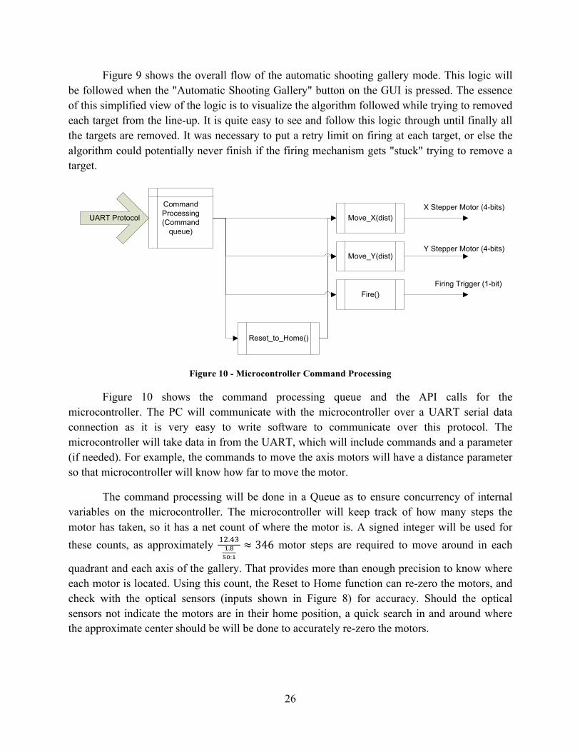
Figure 10 - Microcontroller Command Processing
Figure 10 shows the command processing queue and the API calls for the microcontroller. The PC will communicate with the microcontroller over a UART serial data connection as it is very easy to write software to communicate over this protocol. The microcontroller will take data in from the UART, which will include commands and a parameter (if needed). For example, the commands to move the axis motors will have a distance parameter so that microcontroller will know how far to move the motor.
The command processing will be done in a Queue as to ensure concurrency of internal variables on the microcontroller. The microcontroller will keep track of how many steps the motor has taken, so it has a net count of where the motor is. A signed integer will be used for these counts, as approximately !".!"!.!
!":!≈ 346 motor steps are required to move around in each
quadrant and each axis of the gallery. That provides more than enough precision to know where each motor is located. Using this count, the Reset to Home function can re-zero the motors, and check with the optical sensors (inputs shown in Figure 8) for accuracy. Should the optical sensors not indicate the motors are in their home position, a quick search in and around where the approximate center should be will be done to accurately re-zero the motors.

27
Calibration Start
Establish Area of Interest
Get Image
Find Laser
Raw Image
Center Motors
Find Center of Area of Interest
Center CoordinatesLaser Coordinates
Laser at center?
Manually move robot
No
Yes
Calibration Complete
Figure 11 - Calibration Process Flowchart
The calibration process found in Figure 11 is fairly straight forward. When the process is started the microcontroller will be instructed to center the motors. The user will then be required to set the area of interest for operation. This will allow the system to avoid any noise outside of the gallery being picked up during normal operation. After establishing the area of interest, the coordinates of the center of said area will be determined. An image will be taken from the camera. The image will be processed and the coordinates of the laser will be determined. The coordinates of the laser will be compared to the coordinates of the center. If the laser and center coordinates differ by 5 pixels in either axis the robot will need adjustment. When the laser and center coordinates differ by less than 5 pixels in either direction, calibration is complete and the robot is in an optimal position for standard operation.

28
The process is important to highlight because ideal operation of the system has the gun pointing at the middle of the gallery when the motors are centered. This allows easier distance calculations. The system will function when it is not centered but an offset factor is required.

29
GUI Mock-up (Marimon)
Form TitleForm Title
Stats
[Video image with targets identified/highlighted]
àà
à
à
Fire
Manual Controls
Automatic Shooting Gallery Mode
Figure 12 - GUI Mock-up
Figure 12 shows a quick mock-up of what the main GUI application will look like on the PC. The automatic button triggers the work flow in Figure 9, and the manual controls will allow manual movement of the motors. The video image will be included, with each target highlighted with a color overlay, as well as the current laser position. The stats area will include statistics such as number of targets, total movement, total time, etc. Various possibilities for stats are possible, but none are mandatory for the success of this project, but the area is provided for such findings, and possibly to help debug problems as they arise.

30
Targeting System (Eckhart, Jones, Marimon) The targeting system will serve as a bridge between the software and mechanical portions of the robot. This will include identifying target and laser positions, determining the distance between the current position and next target, and translating that distance into the number of steps each motor must take to acquire tracking on the desired target. The image of the gallery will be processed in a Cartesian coordinate system to create position vectors for the locations of the laser and targets. Within the software, these two position vectors will be used to determine the required change in position of the laser by simply calculating the change from one position to the other. Since the robot’s distance from the target will not change, it will be a constant in the software and will be defined accordingly during the initial setup procedure before autonomous operation, and only the “X” and “Y” components will be interpreted from the imaging portion of the software. The resulting Cartesian vector will then be translated into a spherical coordinate vector, of which the angular components, ! and !, will be quantized into steps required for each motor to take based on the step angle size of the stepper motors (1.8°/step) and the gearing ratio of the worm gear (50:1) by the equations
! = ! ∗ 50 1.8 and
! = ! ∗ 50 1.8, where n is the number of steps the X-axis motor must take and m is the number of steps the Y-axis motor must take. It is important to note that the radial component of this vector will be changing based on the location of the desired target, but there is no direct control of this component. A MATLAB simulation of the effective mapping of the targeting area is depicted in Figure 13. The software will then communicate the quantized number of steps to the microprocessor, which will command the stepper motors to move accordingly. Since the motors naturally move in a spherical way, the utilization of spherical coordinates will allow greater precision and accuracy when moving.

31
Figure 13 - MATLAB Simulation of Effective Targeting Area

32
Control System (Jones)
Motor Control
ImageProcessingSoftware
DPOS CPOSΔPOSTargeting
ProcessingFiringLogic
FiringCommand
ImageFrom
Camera
+-
Figure 14 - Control System Diagram
A control system to guide the laser pointer will be implemented to increase the success rate of the system. The control system will rely on an input signal ( ) from the target processing portion of the software that indicates the desired location for a projectile to be fired. The laser pointer position will be processed by the image processing software to generate a feedback signal representing the current position of the laser pointer ( ). These two signals will be compared to generate a signal that dictates the motion required make the laser point at the desired target ( ). Although the shooting gallery target area is a plane at a fixed distance, a spherical mapping of the gallery will be used to increase the precision of movement calculations. Additionally, the firing logic will receive the desired and current position signals, and a decision to shoot will be made based on the tolerances laid out in the firing logic.

33
Mechanical System (Jones) A lightweight and versatile mechanical system is needed to achieve a final product that fulfills the all engineering and marketing requirements. A three-dimensional representation of the intended mechanical system can be seen in Figure 15, and technical drawings from four perspectives are illustrated in Figure 16. While this mechanical system is very simple in design, it boasts many features that make it ideal for a competition-based environment. All parts of the structure and gearing system are low cost, making design changes and repairs feasible – even at the last minute, if necessary to adapt to the competition. The base, platform, and supports are made from wood, which will allow for easy and precise mounting of the stepper motors. The worm and worm gears are made of commercial grade acetal, which reduces the cost (as opposed to metal) while still providing ample durability to withstand the stress of the system. Additional structural and gearing components (i.e. nuts, bolts, drive shafts, etc.) will be made out of metal.
Figure 15 - 3-D Illustration of Mechanical System

34
Figure 16 - Technical Drawings
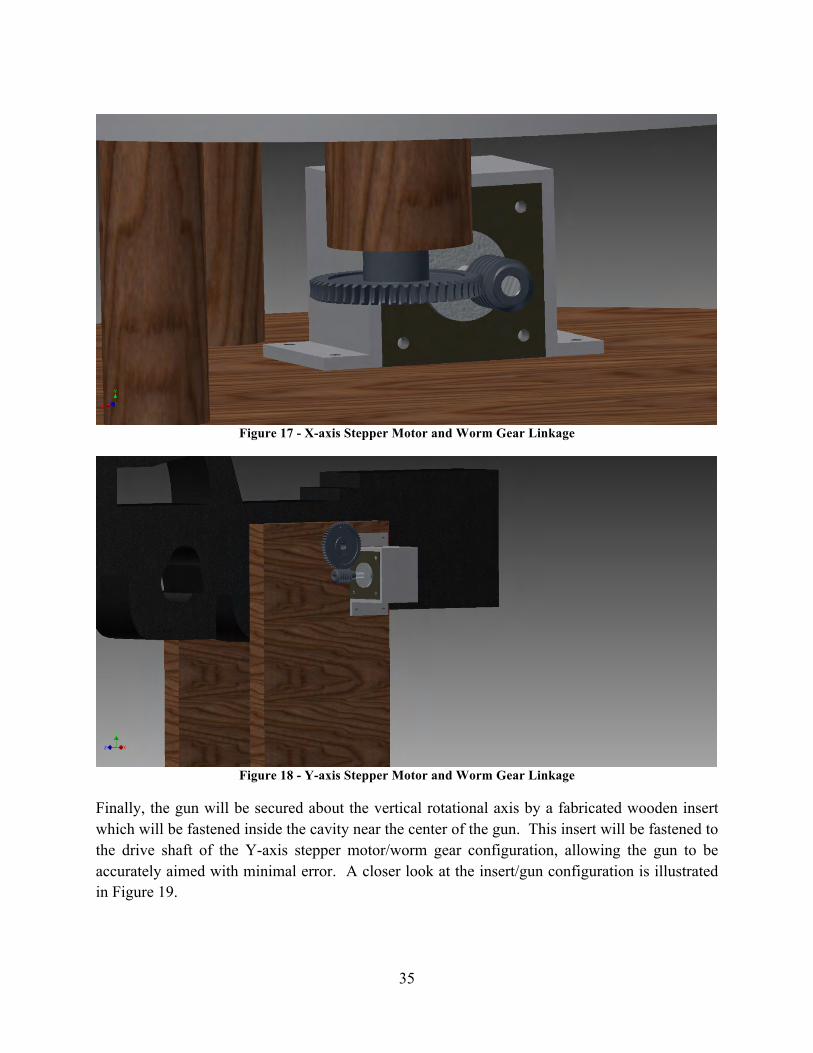
The mechanical system will rely heavily on the use of worm gears and matching worms, which will be driven by stepper motors to provide the aiming capabilities required. Examples of how the gearing linkage will be connected can be found in Figures 17 and 18. The stepper motors will be fastened to the wooden support structures with the use of metal brackets which wrap around the stepper motor, securing it in place. The X-axis worm gear (Figure 17) will be connected to a cylindrical shaft that extends from the bottom of the platform. The platform is connected to the base through wooden support shafts and a lazy-Susan style bearing, allowing for easy movement and rigid support. The Y-axis stepper motor and worm gear configuration (Figure 18) will control the movement of the gun itself via a drive shaft that will span the upright wooden support structures.
35
Figure 17 - X-axis Stepper Motor and Worm Gear Linkage
Figure 18 - Y-axis Stepper Motor and Worm Gear Linkage
Finally, the gun will be secured about the vertical rotational axis by a fabricated wooden insert which will be fastened inside the cavity near the center of the gun. This insert will be fastened to the drive shaft of the Y-axis stepper motor/worm gear configuration, allowing the gun to be accurately aimed with minimal error. A closer look at the insert/gun configuration is illustrated in Figure 19.

36
Figure 19 - Gun-Securing Wooden Insert

37
Design Considerations (Fuldauer, Jones)
In order for the system to accurately position onto targets in order to shoot them, it must be well defined the limits of distances and angles for which the gun will be positioned. The gun will be moving in two axis of motion from a fixed location. Therefore, various distances will be encountered as the gun is positioned away from the center of the gallery. Knowing that the dimensions of the gallery are 5 feet by 5 feet (1.524 meters by 1.524 meters) with the gun at a minimum distance of 10 feet (3.048 meters) from the gallery, the maximum distance of movement in the y-axis can be observed in Error! Not a valid bookmark self-reference.. This distance also includes the displacement from the front of the gun to the approximate mounting point, which we will assume to be 11 inches (0.3056 meters).
The maximum angle that will need to be moved from the center position to the extreme top or bottom points of the gallery in the y-axis can be found by
!! = tan!!0.762 m3.3536 m = 12.80131°
with a maximum distance of
!! = 3.3536 m
cos 12.80131° m = 3.4391 m.
Full range of movement within one single axis will then need to be 25.60262°, twice that of maximum movement from the center position. These calculations also apply to the extreme left and right points of the gallery. This is strictly x-axis movement. When combining movement within both the y-axis and x-axis, the furthest distance necessary to shoot a target will be found at the four corners of the gallery, seen in Figure 21.
H1
3.3536 m
0.762 m Θ1
Figure 20 - Maximum distance and angle for movement in the y-axis

38
The distance within the y-axis (0.762 meters) is already known from the size of the gallery and the distance within the x-axis (3.148 meters) was already found from previous calculation. Using the same process as before, we can find the angle to be
!! = tan!!0.762 m3.4391 m = 12.43917°
with a distance of
!! =3.4391 m
cos 12.43917° m = 3.5218 m.
In addition to knowing our movement limits for distance and angle, we will need to know the precision requirements of our movement angle. A worst-case scenario of aiming at a target on the corner of the gallery will be used. The smallest allowable target diameter size will be 0.5 inches (0.0127 meters). Although there will be no target set up on the direct edge of a gallery corner, this angle will give us an absolute lower bound. The precision of movement should include the ability to aim at one quarter of the diameter of each target. Therefore, the one half of the radius of the smallest allowable target will be used for precision determination as shown by Figure 22. If the system can meet or surpass this precision of angular movement, we can guarantee that the gun will be able to be positioned onto and aimed at all targets.
The angular precision required by the system can then be determined by
3.5218 m
0.003175 m Θ3
H2 0.762 m
Θ2 3.4391 m
Figure 21 - Maximum distance for any target
Figure 22 - Smallest angular movement required for targeting

39
!! = tan!!0.003175 m3.5218 m = 0.05165°.
The effect of gravity may also need to come into consideration, especially with smaller targets. With that in mind, velocity of our projectiles will need to be approximated. Airsoft guns can have a fairly wide range of muzzle velocities. According to the specifications of the airsoft gun intended for use, its muzzle velocity is 400 feet per second (121.6 meters per second). A slower rate typical to other airsoft guns, 250 feet per second (76 meters per second) will be used in determining the effects of gravity so that we do not have to rely on the specification from the airsoft gun manufacturer. With these known velocities, we can approximate the times the projectiles will take to reach gallery targets using our worst-case target distance. For our specification velocity, it will take
3.4391 m
121.6!! × cos (12.43917°)
= 0.02896 seconds
and with our slower velocity, it will take
3.4391 m
76!! × cos (12.43917°)
= 0.04634 seconds.
It is worth noting that these times are determined by assuming that the velocity of the projectiles when striking the targets is the same as the muzzle velocity. Although theoretically this will not be accurate, the final velocity would be difficult to predict. Given the short distances fired, the final velocity will only be a very small amount less than the muzzle velocity. With these times, we can predict the effect of gravity on the vertical position of the projectiles once again assuming constant velocity on coming from the gun and moving towards the gallery. For our specification velocity, the projectile will be vertically displaced by
!! = 121.6ms × sin 12.43917° × 0.02896 s +
12 × −9.8
ms!
× 0.02896 s! = 0.7544398 m
with a drop due to gravity of
!!! = 0.762 m− 0.7544398 m = 0.0075602 m.
With our slower velocity, a projectile will be vertically displaced by
!! = 76ms × sin 12.43917° × 0.04634 s +
12× −9.8
ms!
× 0.04634 s! = 0.7480926 m
with a drop due to gravity of

40
!!! = 0.762 m− 0.7480926 m = 0.0139074 m.
When the laser sight is calibrated, it will be calibrated to accurately hit a target directly where the laser dot is positioned. In other words, the effect of vertical displacement due to gravity will be accounted for. The distance used for calibration will be when the gun is aimed directly in the middle of the gallery. This distance, as stated previously, will be 3.3536 meters. If we can calculate the effects of gravity at this distance, we can then determine the difference of this displacement and the worst case displacement as previously calculated. At this distance, our trajectory angle will be 0 degrees. First, we will need to estimate projectile arrival times at the target once again.
For our specification velocity, it will take
3.3536 m121.6!
!
= 0.02758 seconds
and with our slower velocity, it will take
3.3536 m76!
!
= 0.04413 seconds.
For our specification velocity, the projectile will be vertically displaced by
!! =12 × −9.8
ms! × 0.02758 s! = −0.0037272 m
with a drop due to gravity of
!!! = 0 m− (−0.0037272 m) = 0.0037272 m.
With our slower velocity, a projectile will be vertically displaced by
!! = 12 × −9.8
ms! × 0.04413 s! = −0.0095425 m
with a drop due to gravity of
!!! = 0 m− (−0.0095425 m) = 0.0095425 m.
Therefore, the worst case drop due to gravity after calibrating at 3.3526 meters will be
!!,!! = 0.0075602 m − 0.0037272 = 0.003833 m
at our specification velocity and
!!,!! = 0.0139074 m − 0.0095425 = 0.0043649 m

41
with our slower velocity. With accurate calibration at 3.3536 meters, we can guarantee that a target will not be missed if aimed directly at the center of the target. This is because the worst case vertical displacement is no greater than the radius of the smallest target possible.
Typical stepper motor resolution, or degrees per step, does not fall within the design requirements of the system previously indicated. Therefore, the use of a gear system will need to be implemented. One system that will allow us to provide precise movement is a worm gear system. A visual representation of this type of gear system is shown in Figure 23.
Figure 23 - Worm gear system
The single-enveloping worm would be attached to the stepper motor shaft, with the worm gear attached to another shaft that would move our system. One advantage of this setup is that the single-enveloping worm can turn the worm gear, but not vice versa. This will allow easier control of keeping the system in one fixed position. The gear ratio of the system, or the ratio of turns of the worm gear for every turn of the single-enveloping worm, will reduce the speed and increase the precision of movement. This gear ratio for our system will depend on the precision of the stepper motors that we choose to use. Two possibilities of stepper motor resolution that we have researched are 7.5 degrees per step and 1.8 degrees per step. Because we need a resolution of at least 0.05165 degrees, our gear ratio will need to be at least
! = 7.5°
0.05165 ° = 145.208
for a resolution of 7.5 degrees per step and

42
! = 1.8°
0.05165 ° = 34.85.
The final gear ratios would be chosen by rounding to the nearest available integer greater than these calculated values.
Knowing that the airsoft gun will have a dedicated power supply using a 12 volt input, a laboratory power supply was used to power the gun to measure current. Using an oscilloscope and current probe, in-rush current was measured to peak up to nearly 8 amperes, which can be seen in Figure 24. Steady state current for continuous firing oscillates between 1 ampere and 3 amperes as the motor goes through firing motions.
Figure 24 - In-rush current waveform for gun power
The gun power supply will be based on the TPS54623 “Synchronous Step-Down SWIFT™ Converter” evaluation module, using a 480 kHz operating frequency, 0.6 volt voltage reference, and 12 volt input. The board will be modified to output at the voltage required by the gun motor. The board accepts an enable signal which will be used to disable power from the gun according to safety specification. The gun will be triggered by a signal from the microcontroller which turns on a MOSFET. This prevents gun firing from having to rely on a mechanical system for pulling the physical trigger on the gun. The board implements a hiccup current limit overcurrent protection of approximately 6 amperes. Previous results show that it is possible for the in-rush current to exceed this limit. To avoid a power supply board restart condition, experiments were performed with low resistance values put in series with the power supply wire. The first setup included a 1.2 Ohm resistor soldered onto the positive end of the power wire. This

43
resistance, combined with the resistance of the power wire and the overall impedance of the motor, did not allow enough current draw for the motor to successfully fire. Another setup was performed with two 1.2 Ohm resistors in parallel soldered to the power wire, effectively adding approximately 0.6 Ohms of resistance. This allowed sufficient current draw without exceeding the desirable maximum current of 6 amperes. Based on audible observation, the power supply voltage was increased to 8.0 volts to allow for what sounded like normal operation. Initial research with the airsoft gun indicated that it could be safely used with an 8.0 volt supply. This supply voltage was then decided for use because of the voltage drop across the resistance. A MOSFET with an appropriate resistance from drain to source would allow the system to implement this in-rush current limiting technique.
Estimates for power consumption were evaluated by obtaining current requirements for the microprocessor development board in addition to attaching devices to laboratory power supplies. The development board that we are most likely to use requires a 9 volt input with worst-case current requirements below 2 amperes. Therefore, a 9 volt supply with at least 2 amperes for safety margin should be designed for our microprocessor. A 12 volt supply will be used within the firing mechanism control for powering both stepper motors and the gun. Stepper motor current requirements are estimated to be less than 2 amperes per motor. Evaluation of gun operation while hooked up to a laboratory power supply showed initial current draw of up to 8 amperes, with average current draw between around 2 amperes. With these two major sources of current draw in mind, the 12 volt supply should be able to supply at least 12 amperes of current. The laser emitter we intend to use was also hooked up to a laboratory supply set to 3.3 volts, with no sign of initial current spikes and average current draw around 0.33 amperes. With safety margin, a 3.3 volt supply should be available with at least 0.5 amperes of current supply. A photo-detector circuit will be used for stepper motor positioning control. A 5 volt supply will be used for both circuits, one for each stepper motor. The current draw of a photo-detection circuit has not been evaluated but will likely not require much current, therefore the 5 volt supply should be able to supply at least 1 ampere of current. An estimate for peak power consumption would for this system is
!!"#$ = 9 V × 2 A + 12 V × 12 A + 3.3 V × 0.5 A + 5V × 1 A = 144.65 Watts.
All devices tested and researched will not likely require highly accurate voltage regulation, although a modest threshold of 10% regulation or better will be desirable.

44
4. Parts List (Fuldauer, Jones) Table 29- Parts List
Qty. Refdes Part Num. Description 3 SW1 SPSTNOSW SPST, NO off/on switch 2 P1 TPS54623EVM Gun voltage regulator PCB 3 M2,M3 STEPMTR12V 24V unipolar stepper motor
25 U2-U9 TIP122 Darlington pair transistor, TO-220 5 D1 LEDORANGE Bright orange LED 4 U10,U11 PHTSNSLOGIC Photosensor 4 D2,D3 PHTSNSLED Sidelooking LED 880nm 5 Q1 MOSFETVGS5V MOSFET, 5V Vgs, 400mOhm Rds ON 1 RS232CBL RS-232 cable
10 TO220HTSNK TO-220 Heatsink 1 LZ1 Lazy Susan Bearing 4 WG1,WG2 Worm Gear 4 WS1,WS2 Worm 1 GREAT STUFF Insulating Foam Sealant 1 3/4" Hardwood Plywood 2 1" x 6" Maple Board (Approx. 8' length @ $3.24/ft)
1 GigE UI-5120SE-M GigE camera with HDR CMOS sensor
1 DV164037 Explorer 16 Development Board

45
5. Material Budget Info (Eckhart) Table 30 - Budget Table
Qty. Part Num. Description Cost Cost 3 SPSTNOSW SPST, NO off/on switch $1.43 $4.29 2 TPS54623EVM Gun voltage regulator PCB 25.00 50.00 3 STEPMTR12V 24V unipolar stepper motor 45.33 135.99
25 TIP122 Darlington pair transistor, TO-220 0.53 13.24 5 LEDORANGE Bright orange LED 0.59 2.95 4 PHTSNSLOGIC Photosensor 1.07 4.28 4 PHTSNSLED Sidelooking LED 880nm 0.71 2.84 5 MOSFETVGS5V MOSFET, 5V Vgs, 400mOhm Rds ON 3.25 16.25 1 RS232CBL RS-232 cable 2.08 2.08
10 TO220HTSNK TO-220 Heatsink 0.44 4.43 1 Lazy Susan Bearing 8.50 8.50 4 Worm Gear 5.73 22.92 4 Worm 2.33 9.32 1 GREAT STUFF Insulating Foam Sealant 3.98 3.98 1 3/4" Hardwood Plywood 43.97 43.97 2 1" x 6" Maple Board (Approx. 8' length @ $3.24/ft) 25.92 51.84
1 GigE UI-5120SE-M GigE camera with HDR CMOS sensor
1 DV164037 Explorer 16 Development Board
Total $376.88

46
6. Project Schedules (Eckhart)

47

48
7. Design Team Information
Kyle Eckhart Computer Engineer – Project Leader
Don Fuldauer Computer Engineer – Hardware Manager
Kevin Jones Electrical Engineer – Archivist
Todd Marimon Computer Engineer – Software Manager

49
8. Conclusions and Recommendations (Eckhart)
The group now has a good concept of how the autonomous shooting gallery robot will function with a time frame outlined for successful completion of the robot design and construction. More details have been provided in key areas such as then targeting system, hardware construction, software operation, and the mechanical system. At this point the next steps are to order the necessary parts and start constructing the subsystems.

50
9. References
1. RoboGames, http://www.robogames.net/rules/shooting-gallery.php
2. AForge.NET imaging framework, http://www.aforgenet.com/framework/
3. Worm Gears, http://www.efunda.com/designstandards/gears/gears_introduction.cfm

51
10. Appendices