Embed Size (px)
Citation preview
Proceedings of the 8th International Pipeline ConferenceIPC2010
September 27 - October 1, 2010, Calgary, Alberta, Canada
IPC2010-31485
AUTONOMOUS UNDERWATER RISER INSPECTION TOOL
Claudio CameriniPetrobras SA
Rio de Janeiro, RJ, Brazil
Miguel FreitasCPTI/PUC-Rio
Rio de Janeiro, RJ, Brazil
Ricardo Artigas LangerEngeMOVI
Curitiba, PR, Brazil
Jean Pierre von der WeidCPTI/PUC-Rio
Rio de Janeiro, RJ, Brazil
Robson MarnetPetrobras SA
Macaé, RJ, Brazil
ABSTRACTThe inspection of the vertical section of an offshore
pipeline, known as the riser, plays a critical part of any integrity management program. This section connects the pipe that runs on the seabed to the production facility, be it a floating platform or a FPSO.
Hanging from the platform over deep waters, risers are subject to very extreme operating conditions such as high loads and underwater currents. Corrosion, fatigue, abrasion and damages caused by stray object collisions are factors that must be taken into account, so that oil and gas production are not compromised. A flexible pipeline, a well engineered solution used in most riser installations, provides high reliability while requiring little maintenance but, in spite of advances in project and installation, the inspection of riser pipelines is an immature field where technology has not yet met the user's demands .
In the search for better riser inspection techniques, a project was started to design a new inspection tool. The basic concept consists of an autonomous vehicle, the Autonomous Underwater Riser Inspection tool (AURI), that uses the riser itself for guidance. The AURI tool can control its own velocity and is suited to carry different types of inspection devices. The first AURI prototype is designed to perform visual inspection with an built-in camera system, covering 100% of the external riser surface.
The AURI can reach water depths up to a thousand meters. It was built with several embedded security mechanisms to ensure tool recovery in case of failure and also to minimize chances of damage to the pipeline or other equipment. It uses two electrical thrusters to push it along the riser. The mission is set to a maximum depth to be inspected and is considered complete when one of the following conditions is met: (1) maximum pressure on depth sensor is reached or (2) the length of the run is achieved or (3) maximum mission duration is exceeded or (4) maximum allowed tilt is detected by the inclinometer. Thanks to its positive buoyancy, the AURI will
always return to the surface even if the electronics fail or the batteries get exhausted. This paper presents the first AURI prototype as well as the preliminary test results.
1 INTRODUCTIONA riser is an oil and gas transporting pipeline composed of
polymeric cylindrical elements, reinforced by layers of helical steel wires. Its integrity is threatened by a number of processes, ranging from imperfections during manufacturing to damage during service. According to a 2001 report by MCS International, the single most frequently occurring failure is external sheath damage, which accounts for 25% of the incidents surveyed. When the polymeric sheath fails, the steel wires may suffer from a corrosion process which reduces the typical service life of the structure from 20 to just 2 years [1].
The main type of inspection which is presently carried out in service on this type of structure is visual examination of the outer sheath and of attachments. It allows detection of possible large damages to the riser. This type of inspection is carried out by Remotely Operated Vehicle (ROV) on deep but accessible segments and by divers on the shallow segments. As with any visual technique, it requires an experienced operator (diver) to faithfully report the status of the riser.
Current procedures for riser inspection include, but are not limited to, complete video recording of the entire visible length and registering of any non-conformity occurrences in detail, including precise positioning information [2]. Non-conformity items range from diameter variation, swelling and kinks to fully exposed and damaged armour steel layers. Figures 1 and 2, from Petrobras' Executive Procedure Report [3], present examples of such failure modes as recorded during routine ROV inspections.
1 Copyright © 2010 by ASME
Figure 1. Pipeline with anomalous diameter variation.
Figure 2. Pipeline with polymeric sheath damage and exposed armour steel layer.
The periodicity of such visual inspections depends on the criticality of operations of the pipeline and on the existence of potential threats to the structure, but can be no more than three years apart based on current established procedures [4]. The periodical inspections incur very high costs to the pipeline operators due to the expensive ROV and ROV Support Vessel rental costs.
In order to reduce inspection costs while improving the productivity, a new tool was conceived. The tool is meant to perform a complete inspection of the section between the water surface down to the TDP (Touch Down Point), the end of the catenary curve close to the seabed. Once the tool is launched, such inspection is to performed without any further human assistance, returning automatically to the surface when the mission is completed. To accomplish this the tool must be autonomous both in terms of power supply and control. Since there are no cables running to the surface, the vehicle can be operated in deep waters (1000 m) and, in the next version, ultra deep waters (3000 m). The riser itself is used as guidance making the tool mostly immune to water currents.
This AURI prototype is driven by a pair of electrical thrusters stabilized by a closed loop control system in order to
maintain its speed approximately constant. This prototype is equipped with several cameras that perform a visual inspection of the riser with a 100% coverage of the external surface.
The autonomous riser inspection vehicle concept is covered by BR Patent PI 0605010-7/2008 registered by Petrobras SA [5].
2 THE AURI PROJECTThe AURI tool is composed of several systems that must
operate in a coordinated and seamless way in order to ensure its mission success. It must also guarantee a safe operational environment for the human operators and the riser.
One of the primary concerns of an AURI mission is eliminating the possibility that the AURI gets trapped under the Touch Down Point (TDP) and gets crushed by the weight of the riser causing damage to the pipeline. The tool was designed to be intrinsically safe regarding this matter since, in case of severe electrical failure, it will return automatically to the surface thanks to its positive buoyancy. Mechanical fuses were also added to specific locations on the structure so that it will break in a predicted safe way without releasing sharp hard pieces.
The vehicle is a ring-like structure that is mounted around the riser by a single latching opening having just one degree of freedom. This ensures the easy mounting of the AURI by a diver. The opening mechanism also requires just a single handle which allows a ROV to release and rescue the AURI in case it gets stuck in deep waters.
Many sensor techniques can be adapted as payload for the AURI, such as ultrasound and x-ray technologies. The current prototype is equipped with a visual inspection system composed of a set of digital photographic cameras and high power white LEDs.
2.1 StructureThe first challenge of the project was designing a
mechanism with rollers that could guide the vehicle along the riser while adapting to the diameter variations, swelling and obstacles and that could be easily handled by a diver on deployment and recovery. The structure that acts as the chassis of the AURI must be rigid enough to support all the electromechanical parts during the mission, withstanding the intense water currents, while soft enough to not present any damage risk to the riser. Mechanical fuses were added in order to ensure a predictable mode of failure in case it gets trapped between the riser and the seabed.
To obtain the positive buoyancy of the AURI, special floaters were designed employing high density resin embedded with air-filled glass micro spheres. The floaters were molded on an aluminum structure and covered with thin fiberglass plates. That way, the floaters were incorporated in the structural elements of the vehicle while maintaining a density less than the water. These slim structural elements are very rigid carbon fiber bars that work to bind the floaters together without compromising the desired aggregate density.
2 Copyright © 2010 by ASME
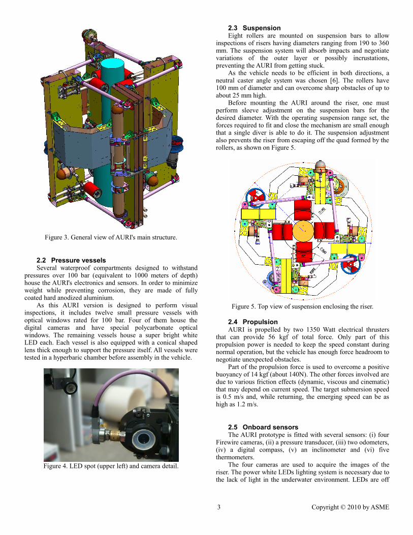
Figure 3. General view of AURI's main structure.
2.2 Pressure vesselsSeveral waterproof compartments designed to withstand
pressures over 100 bar (equivalent to 1000 meters of depth) house the AURI's electronics and sensors. In order to minimize weight while preventing corrosion, they are made of fully coated hard anodized aluminium.
As this AURI version is designed to perform visual inspections, it includes twelve small pressure vessels with optical windows rated for 100 bar. Four of them house the digital cameras and have special polycarbonate optical windows. The remaining vessels house a super bright white LED each. Each vessel is also equipped with a conical shaped lens thick enough to support the pressure itself. All vessels were tested in a hyperbaric chamber before assembly in the vehicle.
Figure 4. LED spot (upper left) and camera detail.
2.3 SuspensionEight rollers are mounted on suspension bars to allow
inspections of risers having diameters ranging from 190 to 360 mm. The suspension system will absorb impacts and negotiate variations of the outer layer or possibly incrustations, preventing the AURI from getting stuck.
As the vehicle needs to be efficient in both directions, a neutral caster angle system was chosen [6]. The rollers have 100 mm of diameter and can overcome sharp obstacles of up to about 25 mm high.
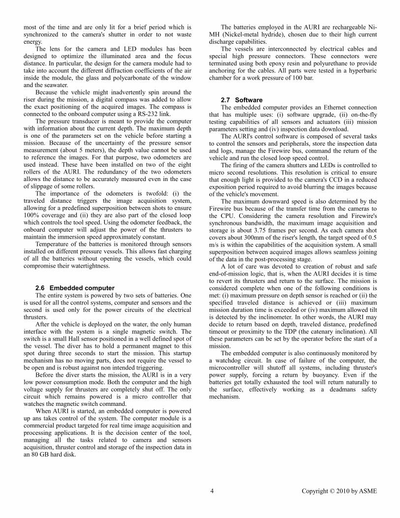
Before mounting the AURI around the riser, one must perform sleeve adjustment on the suspension bars for the desired diameter. With the operating suspension range set, the forces required to fit and close the mechanism are small enough that a single diver is able to do it. The suspension adjustment also prevents the riser from escaping off the quad formed by the rollers, as shown on Figure 5.
Figure 5. Top view of suspension enclosing the riser.
2.4 PropulsionAURI is propelled by two 1350 Watt electrical thrusters
that can provide 56 kgf of total force. Only part of this propulsion power is needed to keep the speed constant during normal operation, but the vehicle has enough force headroom to negotiate unexpected obstacles.
Part of the propulsion force is used to overcome a positive buoyancy of 14 kgf (about 140N). The other forces involved are due to various friction effects (dynamic, viscous and cinematic) that may depend on current speed. The target submersion speed is 0.5 m/s and, while returning, the emerging speed can be as high as 1.2 m/s.
2.5 Onboard sensorsThe AURI prototype is fitted with several sensors: (i) four
Firewire cameras, (ii) a pressure transducer, (iii) two odometers, (iv) a digital compass, (v) an inclinometer and (vi) five thermometers.
The four cameras are used to acquire the images of the riser. The power white LEDs lighting system is necessary due to the lack of light in the underwater environment. LEDs are off
3 Copyright © 2010 by ASME
most of the time and are only lit for a brief period which is synchronized to the camera's shutter in order to not waste energy.
The lens for the camera and LED modules has been designed to optimize the illuminated area and the focus distance. In particular, the design for the camera module had to take into account the different diffraction coefficients of the air inside the module, the glass and polycarbonate of the window and the seawater.
Because the vehicle might inadvertently spin around the riser during the mission, a digital compass was added to allow the exact positioning of the acquired images. The compass is connected to the onboard computer using a RS-232 link.
The pressure transducer is meant to provide the computer with information about the current depth. The maximum depth is one of the parameters set on the vehicle before starting a mission. Because of the uncertainty of the pressure sensor measurement (about 5 meters), the depth value cannot be used to reference the images. For that purpose, two odometers are used instead. These have been installed on two of the eight rollers of the AURI. The redundancy of the two odometers allows the distance to be accurately measured even in the case of slippage of some rollers.
The importance of the odometers is twofold: (i) the traveled distance triggers the image acquisition system, allowing for a predefined superposition between shots to ensure 100% coverage and (ii) they are also part of the closed loop which controls the tool speed. Using the odometer feedback, the onboard computer will adjust the power of the thrusters to maintain the immersion speed approximately constant.
Temperature of the batteries is monitored through sensors installed on different pressure vessels. This allows fast charging of all the batteries without opening the vessels, which could compromise their watertightness.
2.6 Embedded computerThe entire system is powered by two sets of batteries. One
is used for all the control systems, computer and sensors and the second is used only for the power circuits of the electrical thrusters.
After the vehicle is deployed on the water, the only human interface with the system is a single magnetic switch. The switch is a small Hall sensor positioned in a well defined spot of the vessel. The diver has to hold a permanent magnet to this spot during three seconds to start the mission. This startup mechanism has no moving parts, does not require the vessel to be open and is robust against non intended triggering.
Before the diver starts the mission, the AURI is in a very low power consumption mode. Both the computer and the high voltage supply for thrusters are completely shut off. The only circuit which remains powered is a micro controller that watches the magnetic switch command.
When AURI is started, an embedded computer is powered up ans takes control of the system. The computer module is a commercial product targeted for real time image acquisition and processing applications. It is the decision center of the tool, managing all the tasks related to camera and sensors acquisition, thruster control and storage of the inspection data in an 80 GB hard disk.
The batteries employed in the AURI are rechargeable Ni-MH (Nickel-metal hydride), chosen due to their high current discharge capabilities.
The vessels are interconnected by electrical cables and special high pressure connectors. These connectors were terminated using both epoxy resin and polyurethane to provide anchoring for the cables. All parts were tested in a hyperbaric chamber for a work pressure of 100 bar.
2.7 SoftwareThe embedded computer provides an Ethernet connection
that has multiple uses: (i) software upgrade, (ii) on-the-fly testing capabilities of all sensors and actuators (iii) mission parameters setting and (iv) inspection data download.
The AURI's control software is composed of several tasks to control the sensors and peripherals, store the inspection data and logs, manage the Firewire bus, command the return of the vehicle and run the closed loop speed control.
The firing of the camera shutters and LEDs is controlled to micro second resolutions. This resolution is critical to ensure that enough light is provided to the camera's CCD in a reduced exposition period required to avoid blurring the images because of the vehicle's movement.
The maximum downward speed is also determined by the Firewire bus because of the transfer time from the cameras to the CPU. Considering the camera resolution and Firewire's synchronous bandwidth, the maximum image acquisition and storage is about 3.75 frames per second. As each camera shot covers about 300mm of the riser's length, the target speed of 0.5 m/s is within the capabilities of the acquisition system. A small superposition between acquired images allows seamless joining of the data in the post-processing stage.
A lot of care was devoted to creation of robust and safe end-of-mission logic, that is, when the AURI decides it is time to revert its thrusters and return to the surface. The mission is considered complete when one of the following conditions is met: (i) maximum pressure on depth sensor is reached or (ii) the specified traveled distance is achieved or (iii) maximum mission duration time is exceeded or (iv) maximum allowed tilt is detected by the inclinometer. In other words, the AURI may decide to return based on depth, traveled distance, predefined timeout or proximity to the TDP (the catenary inclination). All these parameters can be set by the operator before the start of a mission.
The embedded computer is also continuously monitored by a watchdog circuit. In case of failure of the computer, the microcontroller will shutoff all systems, including thruster's power supply, forcing a return by buoyancy. Even if the batteries get totally exhausted the tool will return naturally to the surface, effectively working as a deadmans safety mechanism.
4 Copyright © 2010 by ASME
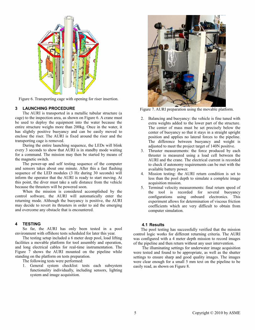
Figure 6. Transporting cage with opening for riser insertion.
3 LAUNCHING PROCEDUREThe AURI is transported in a metallic tubular structure (a
cage) to the inspection area, as shown on Figure 6. A crane must be used to deploy the equipment into the water because the entire structure weighs more than 200kg. Once in the water, it has slightly positive buoyancy and can be easily moved to enclose the riser. The AURI is fixed around the riser and the transporting cage is removed.
During the entire launching sequence, the LEDs will blink every 3 seconds to show that AURI is in standby mode waiting for a command. The mission may then be started by means of the magnetic switch.
The power-up and self testing sequence of the computer and sensors takes about one minute. After this a fast flashing sequence of the LED modules (3 Hz during 30 seconds) will inform the operator that the AURI is ready to start moving. At this point, the diver must take a safe distance from the vehicle because the thrusters will be powered soon.
When the mission is considered accomplished by the control software, the AURI will automatically enter the returning mode. Although the buoyancy is positive, the AURI may decide to revert its thrusters in order to aid the emerging and overcome any obstacle that is encountered.
4 TESTINGSo far, the AURI has only been tested in a pool
environment with offshore tests scheduled for later this year. The testing setup included a 6 meter deep pool, load lifting
facilities a movable platform for tool assembly and operation, and long electrical cables for real-time instrumentation. The Figure 7 shows the AURI mounted on the pipeline while standing on the platform on tests preparation.
The following tests were performed:1. General system checklist: tests each subsystem
functionality individually, including sensors, lighting system and image acquisition.
Figure 7. AURI preparation using the movable platform.
2. Balancing and buoyancy: the vehicle is fine tuned with extra weights added to the lower part of the structure. The center of mass must be set precisely below the center of buoyancy so that it stays in a straight upright position and applies no lateral forces to the pipeline. The difference between buoyancy and weight is adjusted to meet the project target of 140N positive.
3. Thruster measurements: the force produced by each thruster is measured using a load cell between the AURI and the crane. The electrical current is recorded to check if autonomy requirements can be met with the available battery power.
4. Mission testing: the AURI return condition is set to less than the pool depth to simulate a complete image acquisition mission.
5. Terminal velocity measurements: final return speed of the tool is recorded for several buoyancy configurations using onboard electronics. This experiment allows for determination of viscous friction coefficients which are very difficult to obtain from computer simulation.
4.1 ResultsThe pool testing has successfully verified that the mission
control logic works for different returning criteria. The AURI was configured with a 4 meter depth mission to record images of the pipeline and then return without any user intervention.
The illuminating settings for underwater image acquisition were tested and found to be appropriate, as well as the shutter settings to ensure sharp and good quality images. The images were clear enough for a small 5 mm text on the pipeline to be easily read, as shown on Figure 8.
5 Copyright © 2010 by ASME
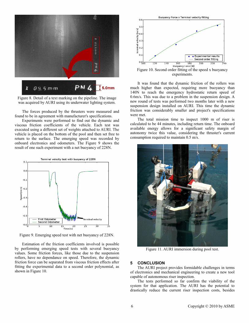
Figure 8. Detail of a text marking on the pipeline. The image was acquired by AURI using its underwater lighting system.
The forces produced by the thrusters were measured and found to be in agreement with manufacturer's specifications.
Experiments were performed to find out the dynamic and viscous friction coefficients of the vehicle. Each test was executed using a different set of weights attached to AURI. The vehicle is placed on the bottom of the pool and then set free to return to the surface. The emerging speed was recorded by onboard electronics and odometers. The Figure 9 shows the result of one such experiment with a net buoyancy of 228N.
Figure 9. Emerging speed test with net buoyancy of 228N.
Estimation of the friction coefficients involved is possible by performing emerging speed tests with several buoyancy values. Some friction forces, like those due to the suspension rollers, have no dependance on speed. Therefore, the dynamic friction force can be separated from viscous friction effects after fitting the experimental data to a second order polynomial, as shown in Figure 10.
Figure 10. Second order fitting of the speed x buoyancy experiments.
It was found that the dynamic friction of the rollers was much higher than expected, requiring more buoyancy than 140N to reach the emergency hydrostatic return speed of 0.6m/s. This was due to a problem in the suspension design. A new round of tests was performed two months later with a new suspension design installed on AURI. This time the dynamic friction was considerably smaller and project's specifications were met.
The total mission time to inspect 1000 m of riser is calculated to be 44 minutes, including return time. The onboard available energy allows for a significant safety margin of autonomy twice this value, considering the thruster's current consumption required to maintain 0.5 m/s.
Figure 11. AURI immersion during pool test.
5 CONCLUSIONThe AURI project provides formidable challenges in terms
of electronics and mechanical engineering to create a new tool capable of autonomous riser inspection.
The tests performed so far confirm the viability of the system for that application. The AURI has the potential to drastically reduce the current riser inspection costs, besides
6 Copyright © 2010 by ASME
being possible to be used as a platform for new types of inspections using other techniques that are currently unavailable in the field.
Offshore tests on riser pipelines are scheduled to take place later this year. A few adjustments are currently being performed on the equipment based on results obtained during pool tests to improve the hydrodynamics and the ease of operation of the tool.
ACKNOWLEDGMENTSThe development team would like to acknowledge our
Petrobras partners for the concept, motivation and funding. Our thanks to the LNDC/Coppe laboratory for providing the testing facilities.
REFERENCES[1] O'Brien, P. and Picksley, J., 2001, “State-of-the-Art
Flexible Riser Integrity Issues”, MCS International.
[2] American Petroleum Institute, 2008, “API RP 17B - Recommended Practice for Flexible Pipe”.
[3] Petroleo Brasileiro S.A., 2010, “PE-2ED-00836-A – Procedimento Executivo para Inspeção no Trecho Dinâmico de Dutos Flexíveis” (internal publication)
[4] Petroleo Brasileiro S.A., 2009, “PE-3ED-01182-G – Diretrizes para Inspeção Periódica em Dutos Flexíveis” (internal publication)
[5] Marnet, R. V. and Silveira Jr, E. L., 2008, “Equipamento para limpeza e inspeção de risers flexíveis em catenária livre”, Patent number PI0605010-7. Petroleo Brasileiro S.A.
[6] Gillespie, T. D., 1992, “Fundamentals of Vehicle Dynamics”, SAE International.
7 Copyright © 2010 by ASME