Embed Size (px)
Citation preview
Welcome to the Saxton Transportation Operations Laboratory
January 10, 2014
U.S. Department of TransportationFEDERAL HIGHWAY ADMINISTRATION
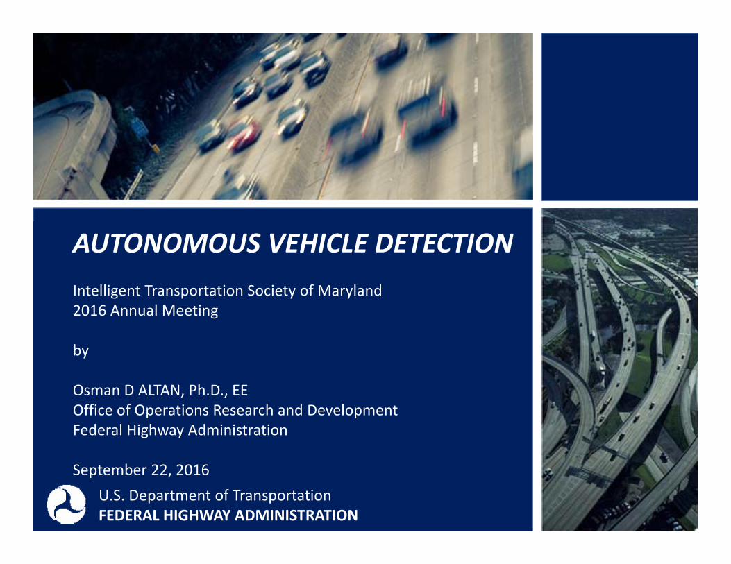
AUTONOMOUS VEHICLE DETECTIONIntelligent Transportation Society of Maryland2016 Annual Meeting
by
Osman D ALTAN, Ph.D., EEOffice of Operations Research and DevelopmentFederal Highway Administration
September 22, 2016
AUTONOMOUS VEHICLE DETECTIONIntelligent Transportation Society of Maryland2016 Annual Meeting
by
Osman D ALTAN, Ph.D., EEOffice of Operations Research and DevelopmentFederal Highway Administration
September 22, 2016U.S. Department of TransportationFEDERAL HIGHWAY ADMINISTRATION
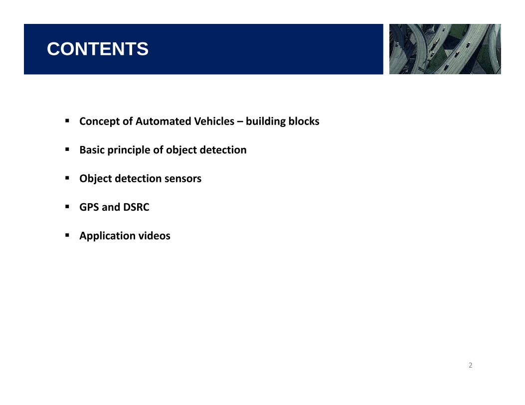
CONTENTS
2
Concept of Automated Vehicles – building blocks
Basic principle of object detection
Object detection sensors
GPS and DSRC
Application videos
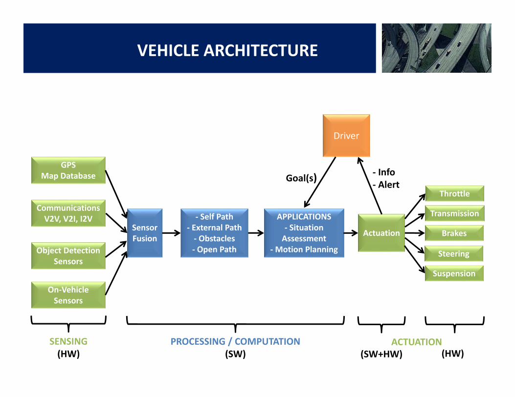
SensorFusion
‐ Self Path‐ External Path‐ Obstacles‐ Open Path
APPLICATIONS‐ Situation Assessment
‐Motion Planning
Actuation
GPSMap Database
CommunicationsV2V, V2I, I2V
Object Detection Sensors
On‐Vehicle Sensors
Driver
Throttle
Brakes
Steering
Suspension
Goal(s) ‐ Info‐ Alert
SENSING(HW) (HW)
PROCESSING / COMPUTATION(SW) (SW+HW)
ACTUATION
VEHICLE ARCHITECTURE
Transmission
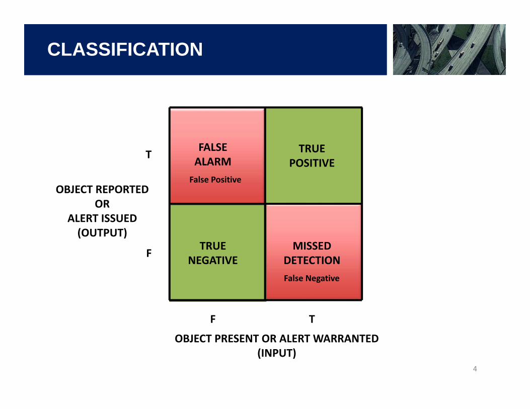
CLASSIFICATION
4
OBJECT REPORTEDOR
ALERT ISSUED(OUTPUT)
OBJECT PRESENT OR ALERT WARRANTED (INPUT)
T
T
F
F
TRUE POSITIVE
TRUE NEGATIVE
FALSE ALARM
MISSED DETECTION
False Positive
False Negative
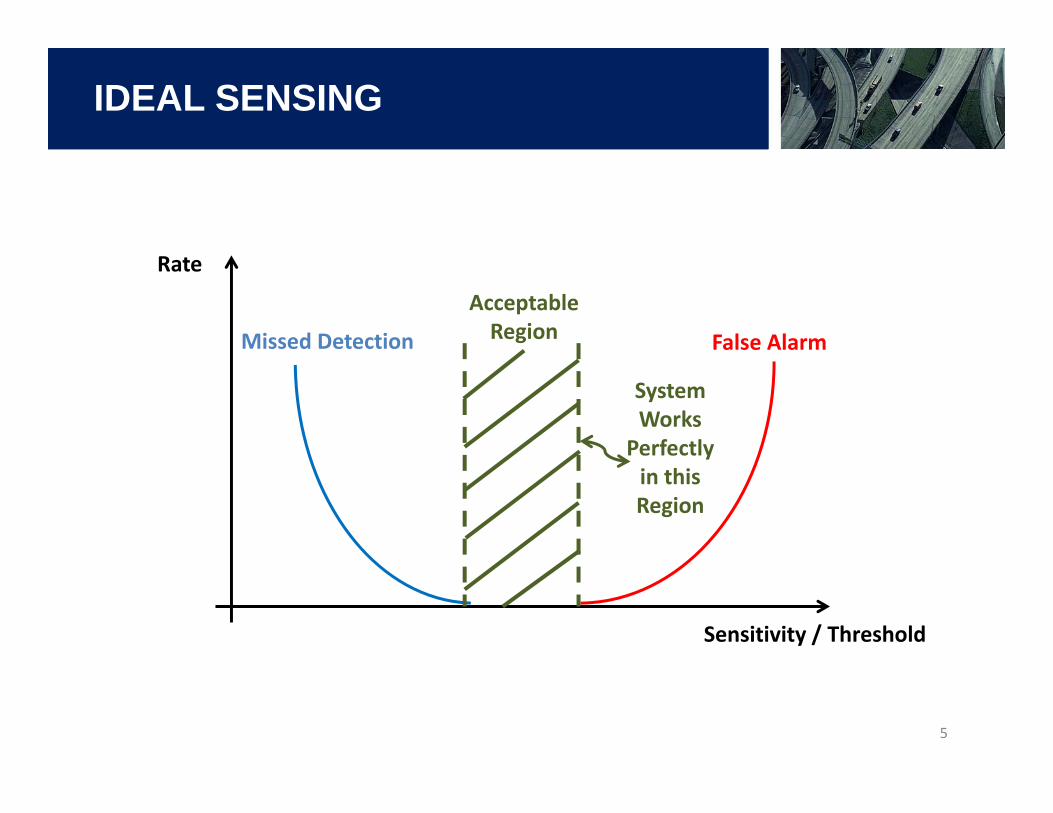
IDEAL SENSING
5
Sensitivity / Threshold
Rate
False AlarmMissed Detection
AcceptableRegion
System Works
Perfectly in this Region
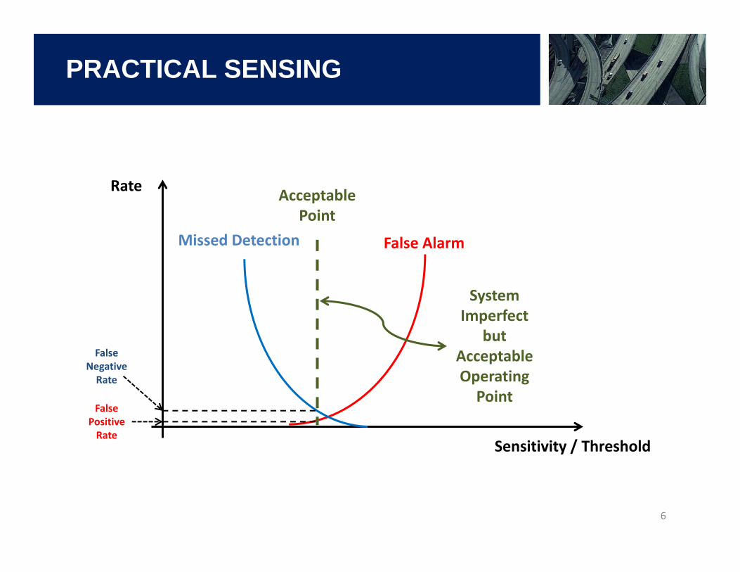
PRACTICAL SENSING
6
False AlarmMissed Detection
AcceptablePoint
System Imperfect
but Acceptable Operating Point
False Positive Rate
False Negative Rate
Rate
Sensitivity / Threshold
SENSORS
7
AUTONOMOUS SYSTEMSSensors based on different technologies are used:
‐ Radar‐ Lidar‐ Camera with image/machine processing
Sensor fusion utilized to improve robustness and reliability of object detection. Especially, (radar – camera) or (lidar – camera) combinations are common.
Each technology has its advantages and disadvantages. e.g., lidarcannot measure range rate, camera cannot measure range and range rate. These parameters need to be computed.
Sensors are capable of detecting objects within a specified ‘solid angle’ within a finite range (volume). Basically, the solid angle is defined in simpler terms as azimuth angle and elevation angle. e.g., radars have a fuzzy detection boundaries. Range and solid angle defines the detection volume.
RADAR
8
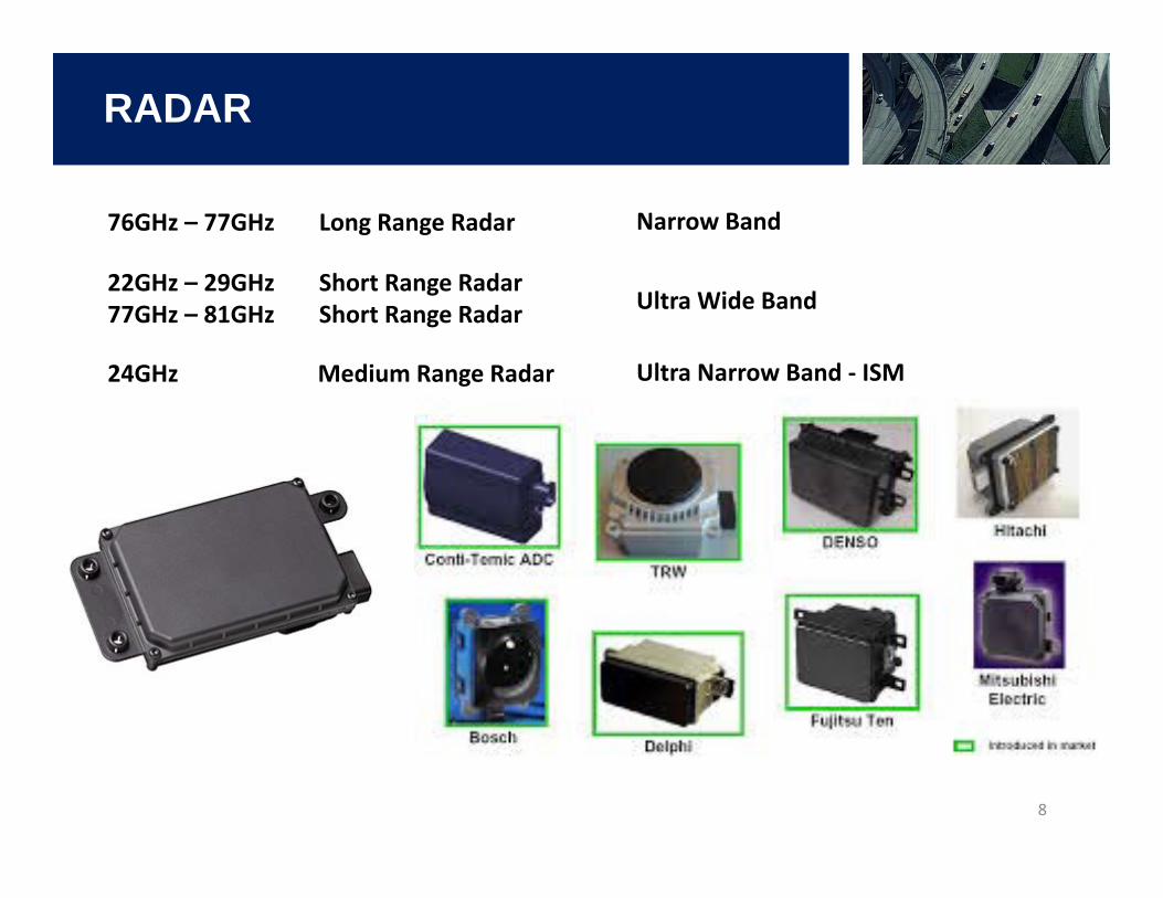
76GHz – 77GHz Long Range Radar
22GHz – 29GHz Short Range Radar77GHz – 81GHz Short Range Radar Ultra Wide Band
Narrow Band
24GHz Medium Range Radar Ultra Narrow Band ‐ ISM
RADAR
9
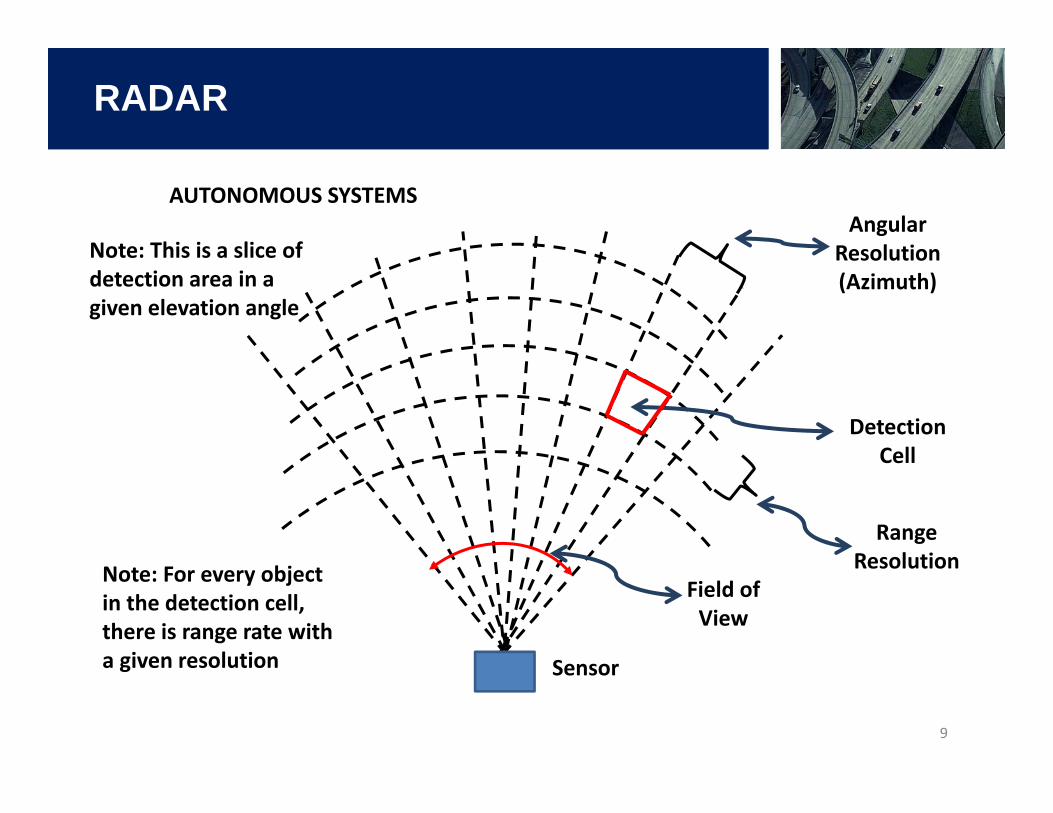
AUTONOMOUS SYSTEMS
DetectionCell
AngularResolution(Azimuth)
RangeResolution
Sensor
Field ofView
Note: This is a slice of detection area in a given elevation angle
Note: For every object in the detection cell, there is range rate with a given resolution
LIDAR
10
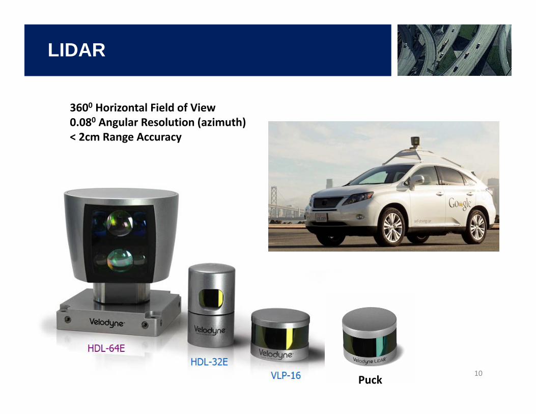
3600 Horizontal Field of View0.080 Angular Resolution (azimuth)< 2cm Range Accuracy
Puck
LIDAR
11
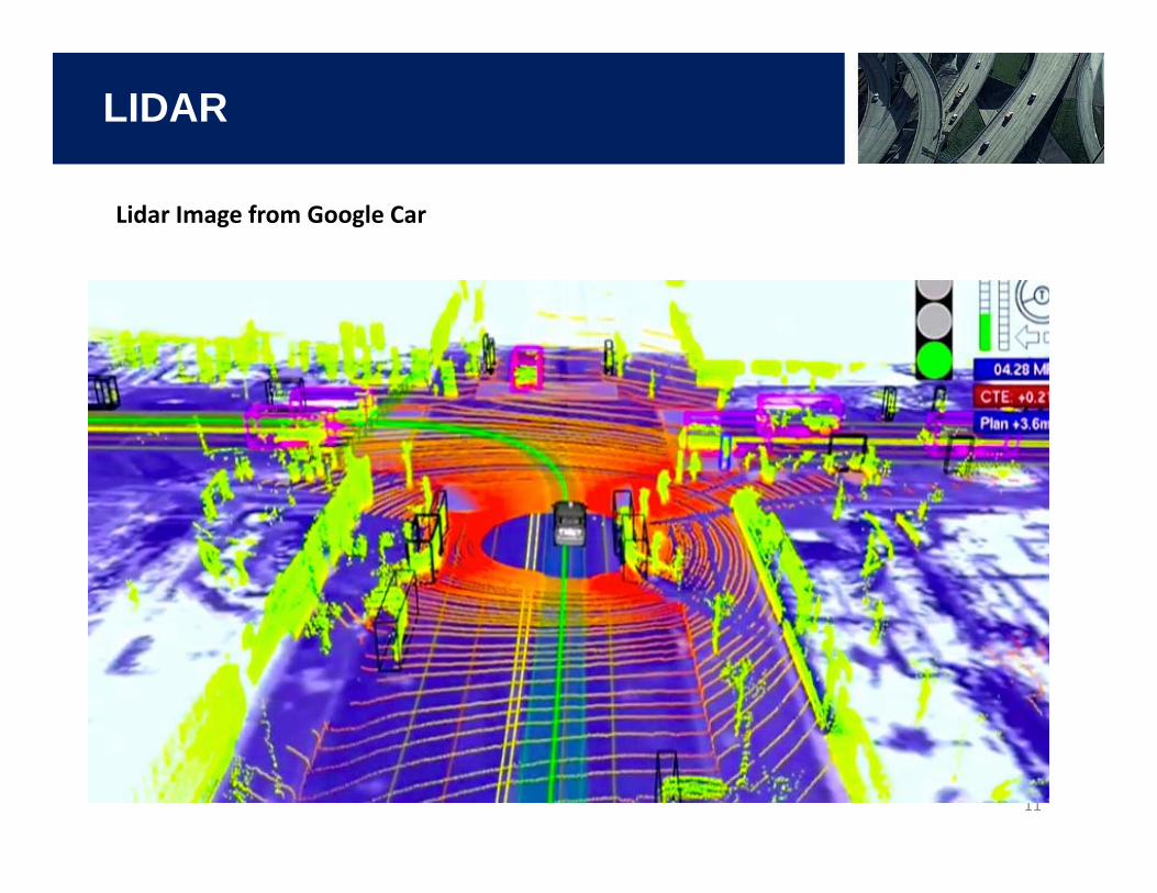
Lidar Image from Google Car
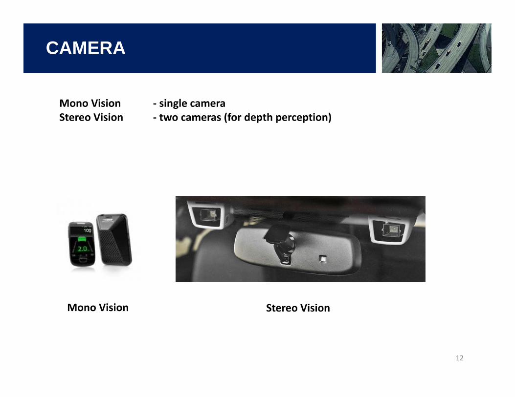
CAMERA
12
Mono Vision ‐ single cameraStereo Vision ‐ two cameras (for depth perception)
Mono Vision Stereo Vision
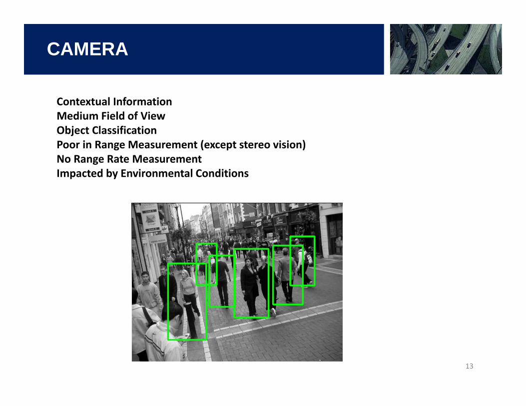
CAMERA
13
Contextual InformationMedium Field of ViewObject ClassificationPoor in Range Measurement (except stereo vision)No Range Rate MeasurementImpacted by Environmental Conditions
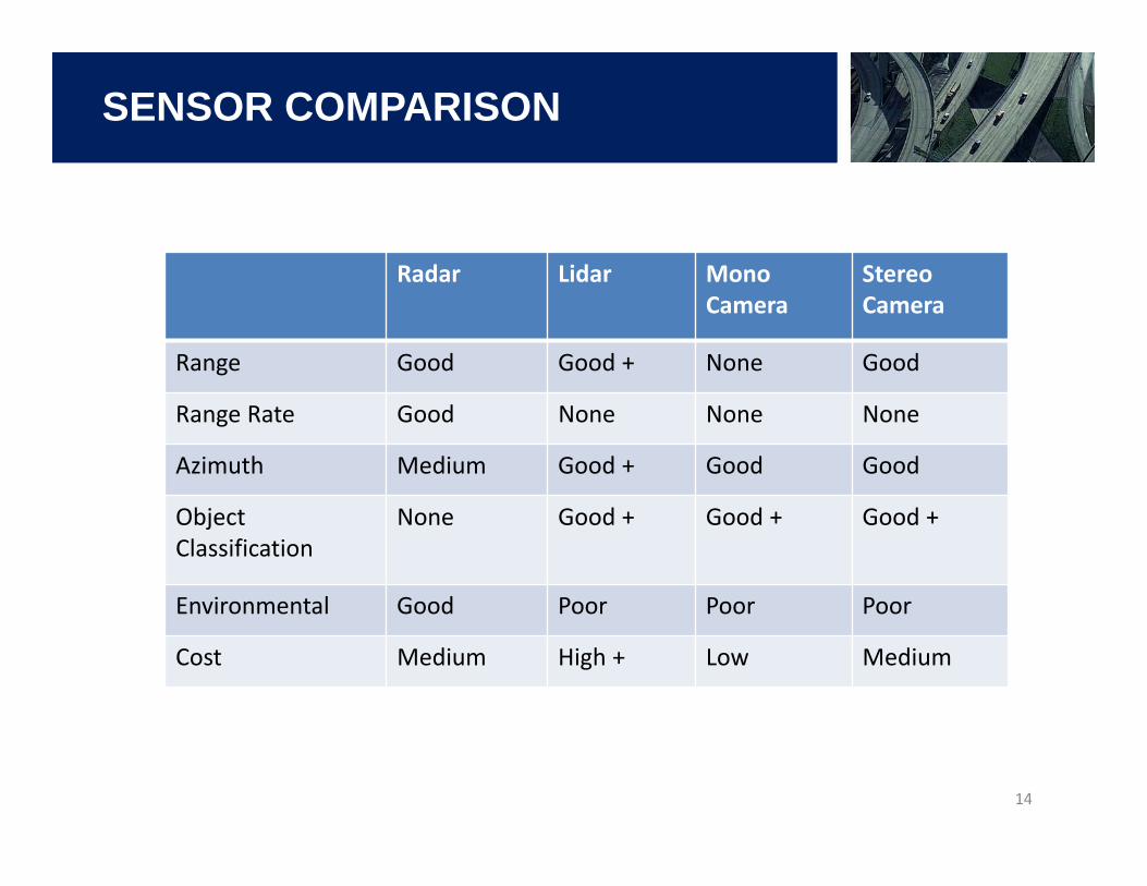
SENSOR COMPARISON
14
Radar Lidar Mono Camera
StereoCamera
Range Good Good + None Good
Range Rate Good None None None
Azimuth Medium Good + Good Good
Object Classification
None Good + Good + Good +
Environmental Good Poor Poor Poor
Cost Medium High + Low Medium
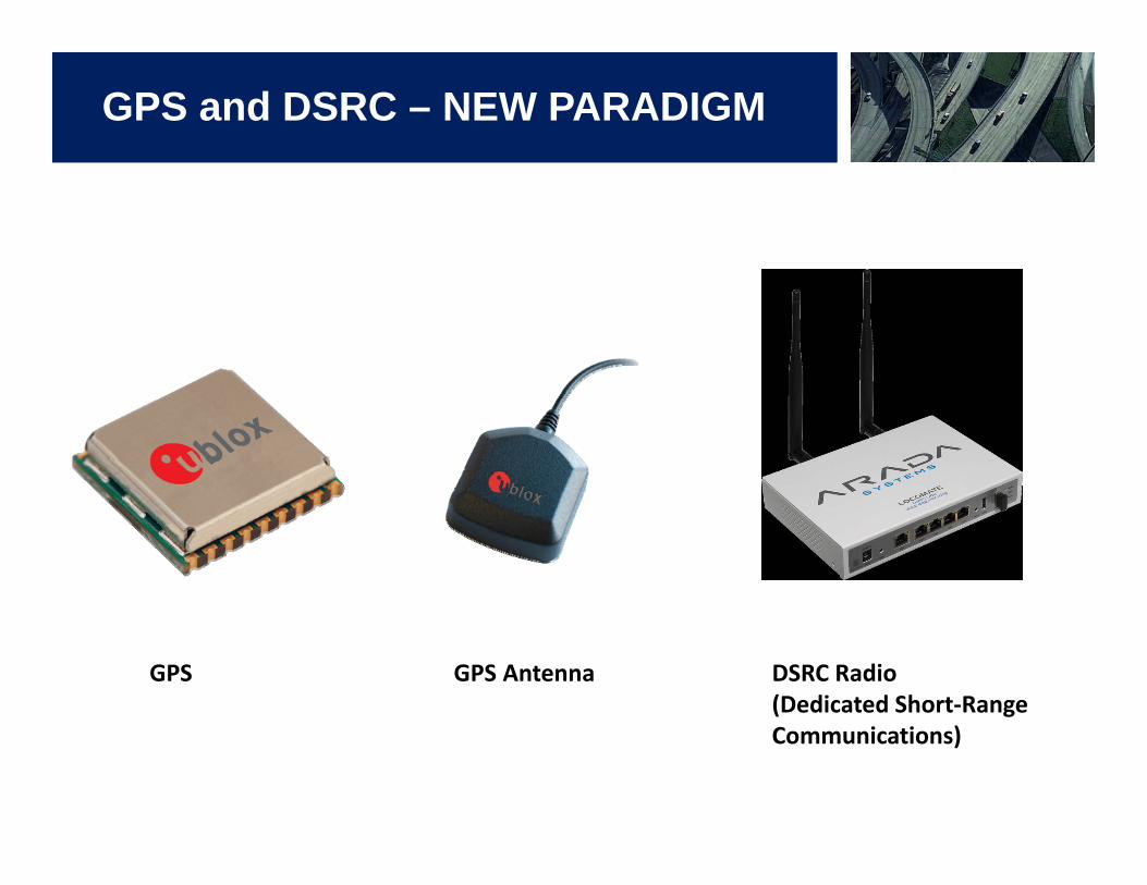
GPS and DSRC – NEW PARADIGM
GPS GPS Antenna DSRC Radio(Dedicated Short‐Range Communications)
DSRC
16
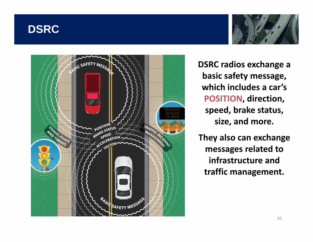
DSRC radios exchange a basic safety message, which includes a car’s POSITION, direction, speed, brake status, size, and more.
They also can exchange messages related to infrastructure and traffic management.
COMPARISON
17
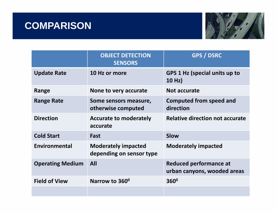
OBJECT DETECTION SENSORS
GPS / DSRC
Update Rate 10 Hz or more GPS 1 Hz (special units up to 10 Hz)
Range None to very accurate Not accurate
Range Rate Some sensors measure, otherwise computed
Computed from speed and direction
Direction Accurate to moderately accurate
Relative direction not accurate
Cold Start Fast Slow
Environmental Moderately impacted depending on sensor type
Moderately impacted
Operating Medium All Reduced performance at urban canyons, wooded areas
Field of View Narrow to 3600 3600
SENSOR PERFORMANCE
18
Currently GPS is not sufficiently accurate for many applications, especially real‐time control related apps.
On‐board sensors are much more accurate, especially ‘sensor fusion’ improves the performance significantly with only marginal cost impact.
GPS black‐outs are common in locations such as urban canyons, wooded areas, tunnels, long underpasses, etc.
On‐board sensors are functional under the above conditions, although some of them have limitations under certain environmental conditions.
Update rate of low‐cost GPS is not sufficient for real‐time applications. On‐board sensors have a minimum of 10Hz update rate.
Sensor fusion between GPS data and on‐board sensor data is not recommended, GPS data contaminates the accurate on‐board sensor data.
GPS still serves as very useful input in many applications, and even in real‐time control apps from a different perspective depending on the application.
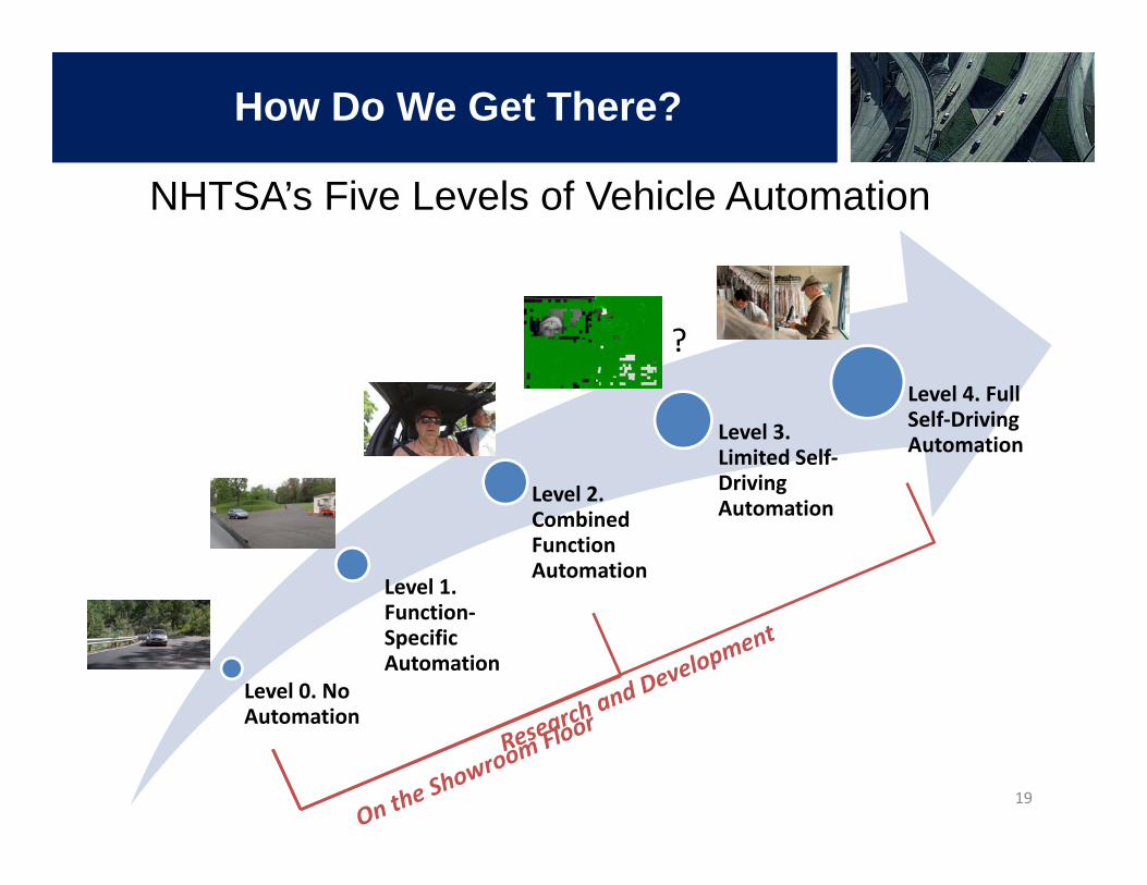
Level 0. No Automation
Level 1. Function‐Specific Automation
Level 2. Combined Function Automation
Level 3. Limited Self‐Driving Automation
Level 4. Full Self‐Driving Automation
How Do We Get There?
NHTSA’s Five Levels of Vehicle Automation
?
19
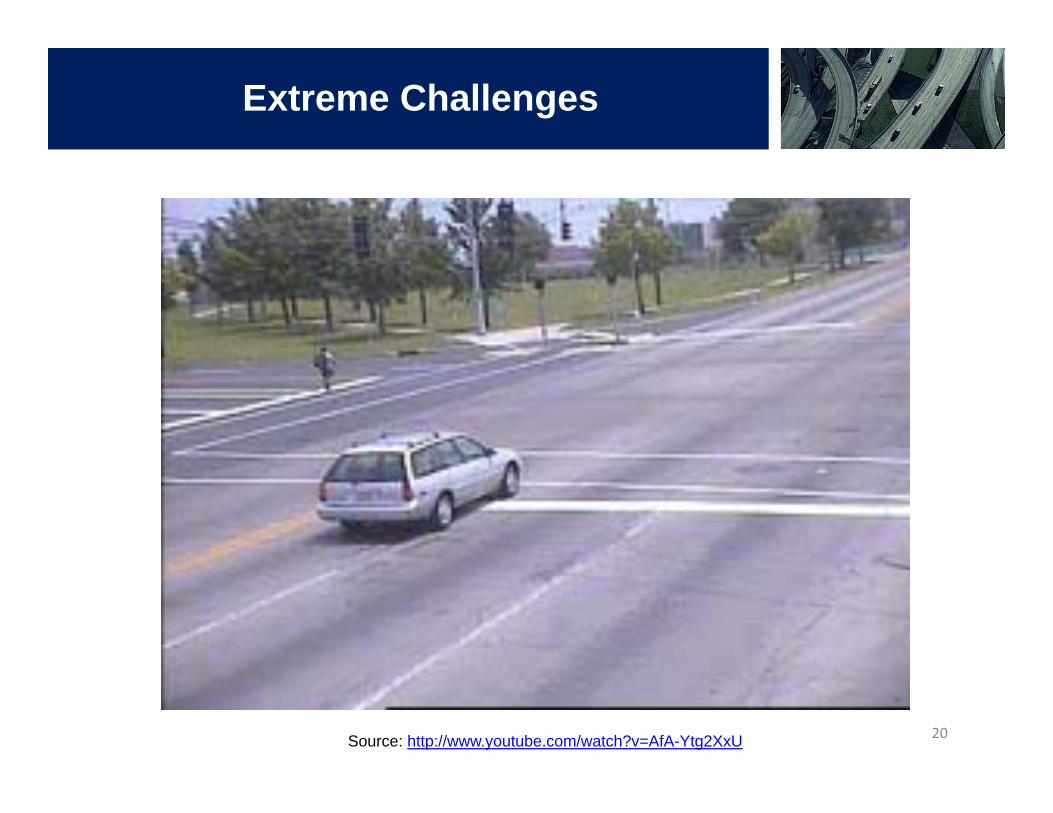
Extreme Challenges
Source: http://www.youtube.com/watch?v=AfA-Ytg2XxU 20
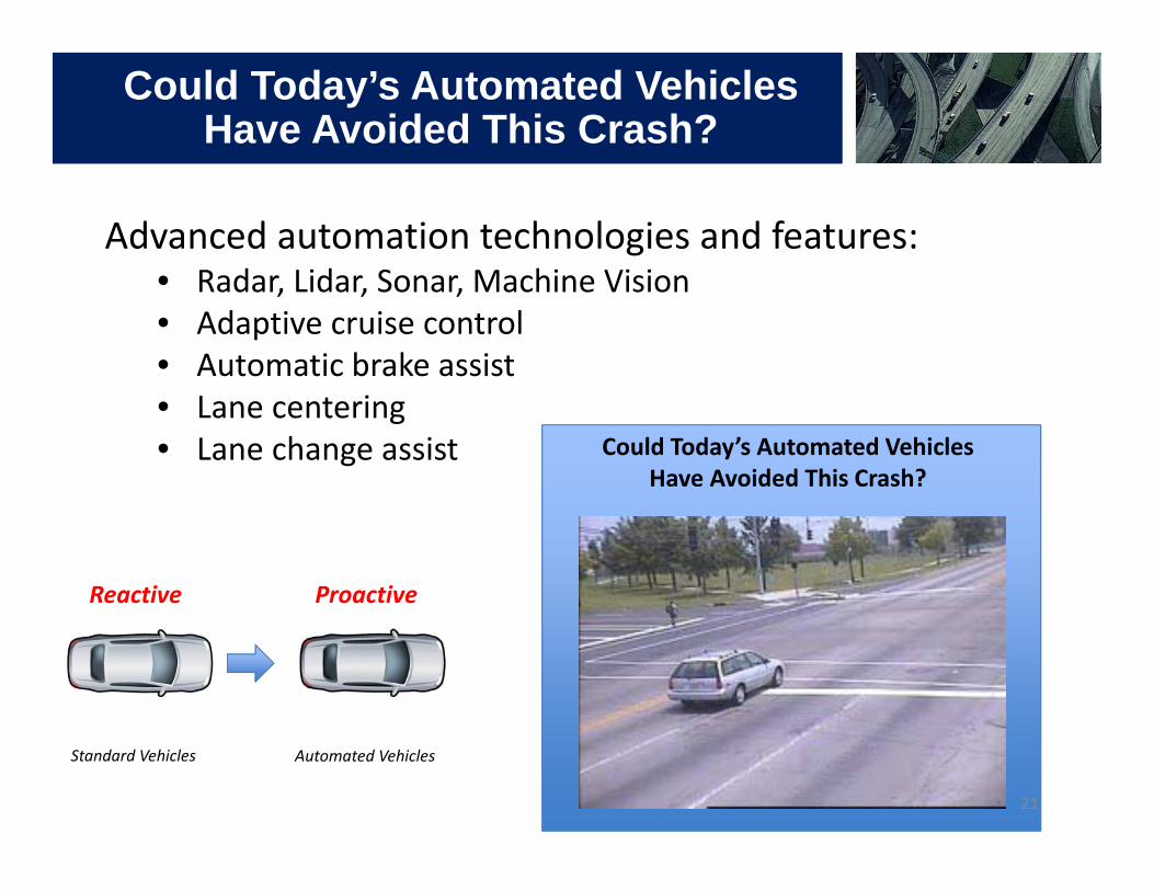
Could Today’s Automated Vehicles Have Avoided This Crash?
Standard Vehicles
Advanced automation technologies and features:• Radar, Lidar, Sonar, Machine Vision• Adaptive cruise control• Automatic brake assist• Lane centering• Lane change assist
Automated Vehicles
Proactive Reactive
Could Today’s Automated Vehicles Have Avoided This Crash?
21
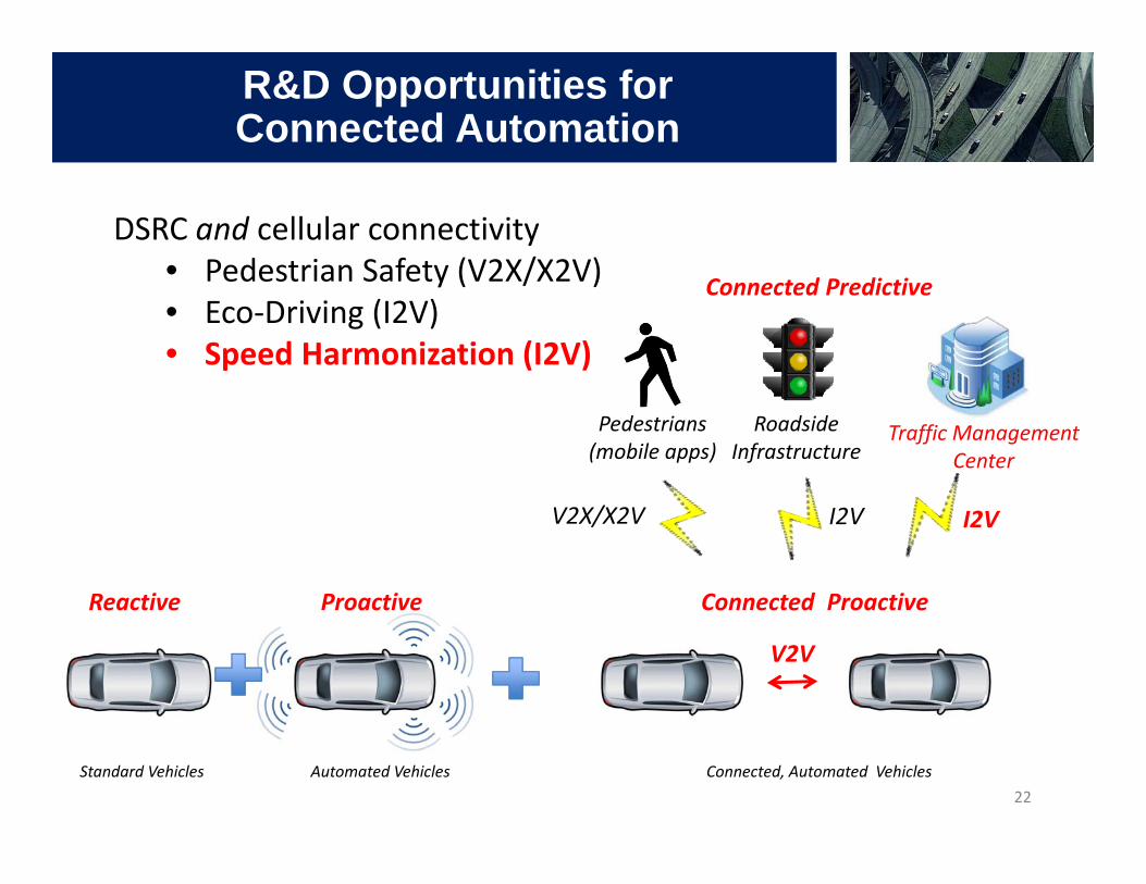
DSRC and cellular connectivity• Pedestrian Safety (V2X/X2V)• Eco‐Driving (I2V)• Speed Harmonization (I2V)
Standard Vehicles Automated Vehicles Connected, Automated Vehicles
Traffic Management Center
RoadsideInfrastructure
Connected Predictive
Reactive Proactive Connected Proactive
V2V
I2V I2V
Pedestrians (mobile apps)
R&D Opportunities for Connected Automation
V2X/X2V
22
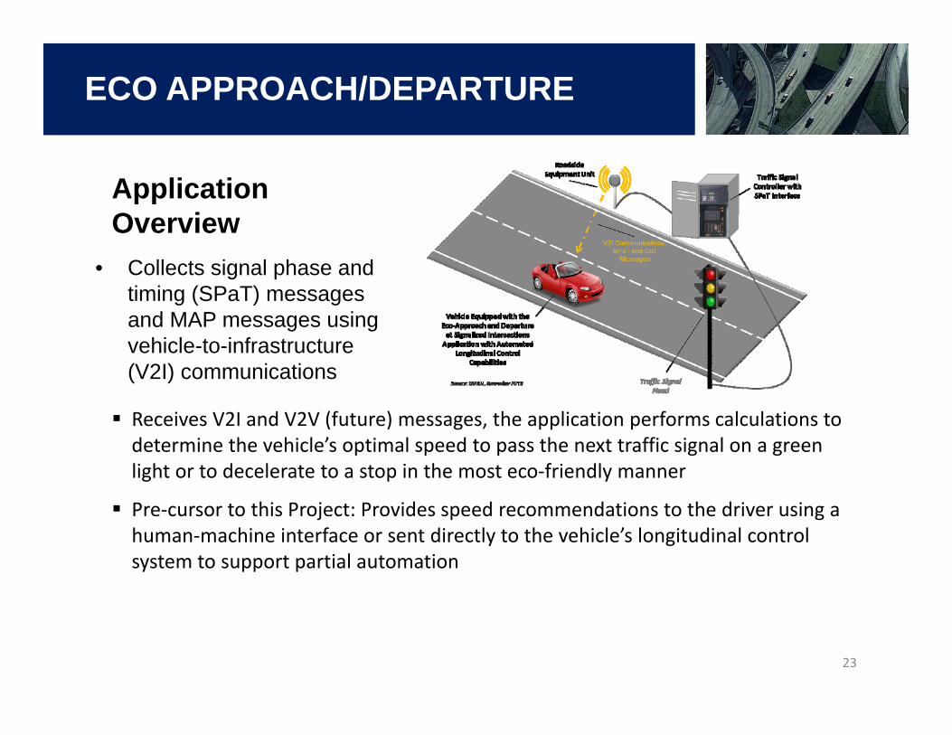
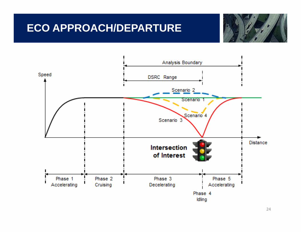
ECO APPROACH/DEPARTURE
23
Application Overview
• Collects signal phase and timing (SPaT) messages and MAP messages using vehicle-to-infrastructure (V2I) communications
Receives V2I and V2V (future) messages, the application performs calculations to determine the vehicle’s optimal speed to pass the next traffic signal on a green light or to decelerate to a stop in the most eco‐friendly manner
Pre‐cursor to this Project: Provides speed recommendations to the driver using a human‐machine interface or sent directly to the vehicle’s longitudinal control system to support partial automation
24
ECO APPROACH/DEPARTURE
VIDEO
25
SLOW DOWN SCENARIO
The Pathway Forward
Automated vehicle technologies are revolutionary
A connected, automated transportation system is the next revolution
26

We Want You: Be a Part of the Next Revolution!
Universities• Exploratory Advanced Research (EAR) Program• National Science Foundation
Researchers• National Research Council
(NRC) Fellowships• Eisenhower Research Fellows• FHWA Student Internships• Intergovernmental Personnel Act
Agreements (IPA)Industry• Connected Vehicle PlugFests• OEMs (Crash Avoidance Metrics Partners, LLC)
27
To Learn More
Visit• FHWA Office of Operations Website:
http://ops.fhwa.dot.gov/• Turner-Fairbank Highway Research Center
Website: http://www.fhwa.dot.gov/research/tfhrc/offices/operations/
• FHWA R&T Agenda: http://www.fhwa.dot.gov/research/fhwaresearch/agenda/challengeAreas.cfm?cid=2
Contact– [email protected] 28