Embed Size (px)
Citation preview
Test Report
Report No 247/ 7340511 This Report consists of 41 pages
Client Electrical Safety Council 18 Buckingham Gate London SW1E 6LB
Authority & date BSI Estimate Acceptance No 0000191154 dated 12 March 2009 Equipment Record No 10104656 dated 04 March 2009
Items tested
Eight samples of recess mounting luminaires, of types and designs as detailed within this Test Report
Specification BS EN 60598-2-2: 1997 + A1 and BS EN 60598-1: 2008 Limited tests as detailed on page 3 of this Test Report
Results As detailed within this Test Report
Prepared by P R Overington Project Leader
Authorized by C Stratford Laboratory Manager, Lighting Technology
Issue Date 27 May 2009
Conditions of issue This Test Report is issued subject to the conditions stated in current issue of PS082 'General conditions relating to acceptance of testing'. The results contained herein apply only to the particular sample/s tested and to the specific tests carried out, as detailed in this Test Report. The issuing of this Test Report does not indicate any measure of Approval, Certification, Supervision, Control or Surveillance by BSI of any product. No extract, abridgement or abstraction from a Test Report may be published or used to advertise a product without the written consent of the Managing Director, BSI Testing Services, who reserves the absolute right to agree or reject all or any of the details of any items or publicity for which consent may be sought.
BSI Maylands Avenue Hemel Hempstead Hertfordshire HP2 4SQ Telephone: (08450) 765600

Report Reference No 247/7340511
Page 2 of 41 Introduction The samples of recess mounted tungsten halogen lamp luminaires were commercially available products that were purchased for testing by the Electrical Safety Council. The samples were submitted on 04 March 2009 for a limited safety assessment according to an agreed test schedule. The samples were allocated the following type references for identification purposes:
RL-1: Recess mounting luminaire designed to operate one 12V 35W GX5.3 aluminium reflector tungsten halogen lamp from a remote mounting transformer. For the purpose of the tests, a commercially available lamp and transformer were purchased and used. RL-2: Recess mounting luminaire designed to operate one 12V 50W GU5.3 aluminium reflector tungsten halogen lamp from a remote mounting transformer. For the purpose of the tests, the lamp and transformer supplied with the product were used.
RL-3: Recess mounting luminaire designed to operate one 12V 50W MR16 tungsten halogen lamp from a remote mounting transformer. For the purpose of the tests, a commercially available lamp and transformer were purchased and used. RL-4: Recess mounting luminaire designed to operate one 12V 50W GU5.3 aluminium tungsten halogen lamp from a remote mounting transformer. For the purpose of the tests, a commercially available lamp and transformer were purchased and used. RL-5: Recess mounting luminaire designed to operate one 230V 50W GU10 tungsten halogen lamp. For the purpose of the tests, a commercially available lamp was purchased and used. RL-6: Recess mounting luminaire designed to operate one 240V 50W GU10 tungsten halogen lamp. For the purpose of the tests, a commercially available lamp was purchased and used. RL-7: Recess mounting luminaire designed to operate one 12V 50W MR16 tungsten halogen lamp from a remote mounting transformer. For the purpose of the tests, a commercially available lamp and transformer were purchased and used. RL-8: Recess mounting luminaire designed to operate one 12V 50W GX5.3 tungsten halogen lamp from a remote mounting transformer. For the purpose of the tests, a commercially available lamp and transformer were purchased and used.
For further details of the samples submitted, please refer to the photographic evidence contained within pages 34 to 41 of this Test Report. Relevant Specifications The Specifications used during the assessments performed were as follows. BS EN 60598-2-2: 1997 including Amendment 1 – Recess luminaires BS EN 60598-1: 2008 – Luminaires: General requirements and tests

Report No 247/7340511
Page 3 of 41 Test schedule The test schedules applied in the assessment of the lighting chains and transformers were as follows. BS EN 60598-2-2: 1997 including Amendment 1 Clause 2.5 Marking Clause 2.6 Construction: Limited to Sub-Clause 4.25 Sharp edges of BS EN 60598-1: 2008 Clause 2.10 External and internal wiring: Limited to Sub-Clause 5.3.2 Sharp edges of BS EN 60598-1: 2008 Clause 2.12 Endurance tests and thermal tests: Limited to Sub-Clauses 12.3 thermal endurance and 12.4 Thermal test (normal operation) of BS EN 60598-1: 2008 The Client also requested some additional tests to be performed, to assess the thermal properties of the luminaires under two separate test conditions:
1) Thermal endurance test: Test recess covered with two layers of insulation 2) Abnormal thermal test: Operation with a lamp that does not reflect the heat forwards
The applied tests were based upon the guidance provided in the following test Clauses:
BS EN 60598-2-2: 1997 including Amendment 1 Clause 2.12 Endurance tests and thermal tests: Limited to Sub-Clauses 12.3 thermal endurance and 12.4 Thermal test (normal operation) of BS EN 60598-1: 2008
Notes: Sample reference RL-4 was not subjected to the additional test with two layers of insulation, as the original test programme covered this mode of operation. The luminaire marking details and installation leaflet for this product allowed the luminaire to be covered in normal use. Sample references RL-5; RL-6; RL-7 & RL-8 were not subjected to the thermal test with a non-aluminium lamp as the original test programme covered this mode of performance. Results The results of the limited tests and inspections performed on the samples submitted are contained on the following pages of this Test Report.

Report No 247/7340511
Page 4 of 41 RESULTS SECTION
Sample RL-1 Part 1 – Test requirements according to Specification requirements
EN 60 598-1
Cl. Requirement – Test Result 3 MARKING 3.2 Mandatory markings See comments F Position of the marking P Format of symbols/text P 3.3 Additional information See comments P 3.4 Test with water P Test with hexane P Legible after test P Label attached P 4 CONSTRUCTION 4.25 No sharp point or edges P 5 EXTERNAL AND INTERNAL WIRING 5.3.2 Sharp edges etc. P 12 ENDURANCE TEST AND THERMAL TEST 12.3 Endurance test P 12.4 Thermal test (normal operation) See Table 1 Part 2 – Additional tests according to Clients own requirements 12 ENDURANCE TEST AND THERMAL TEST 12.3 Endurance test Covered with two layers of
insulation: See comments
- Thermal test (abnormal operation) Incorrect lamp fitted: See Table 1
Key: P = Pass F = Fail NT = Not tested

Report No 247/7340511
Page 5 of 41
Table 1: Temperature measurements, thermal tests of Section 12 Type reference ............................................. : RL-1
Lamp used.................................................... : 12V 35W
Lamp control gear used................................ : Electronic transformer rated 240V (11.6V 60VA output)
Mounting position of luminaire...................... : Test recess
Supply wattage (W) ...................................... : 37.9
Supply current (A) ........................................ : 0.151
Supply voltage (V) ........................................ : 255.5 Table: Measured temperatures corrected for ta = 25 °C:
Temperature (°C) of part Normal Abnormal
Test Limit Test Limit
Transformer case 68 85 80 85
Cord grip moulding 59 # 76 #
Terminal enclosure side 70 # 104 #
Terminal block 79 # 89 #
Glass fibre insulated cable at terminal block
77 200 98 200
Terminal block cover 76 # 97 #
Glass fibre insulated cable at entry to luminaire enclosure
94 200 120 200
Luminaire body – top (metal) 84 - 111 -
Glass fibre insulated cable at lampholder 160 200 194 200
Ceramic lampholder 158 - 188 -
Front bezel cover 67 # 93 #
Minimum distance from lighted objects: 0.5m
38 90 31 90
Test recess above luminaire 61 90 76 90
Notes
1) The sample was operated at 1.06 x the maximum rated input voltage of the transformer i.e. 1.06 x 240 = 254.4V~.
2) The voltage recorded above is the noted voltage at the time of measurement.
3) # - Plastic moulded component and therefore the material and applied thermal limit is
unknown
4) The abnormal test is with a non-aluminium reflector lamp fitted

Report No 247/7340511
Page 6 of 41 Sample RL-2 Part 1 – Test requirements according to Specification requirements
EN 60 598-1
Cl. Requirement – Test Result 3 MARKING 3.2 Mandatory markings P Position of the marking P Format of symbols/text See comments F 3.3 Additional information P 3.4 Test with water P Test with hexane P Legible after test P Label attached P 4 CONSTRUCTION 4.25 No sharp point or edges P 5 EXTERNAL AND INTERNAL WIRING 5.3.2 Sharp edges etc. P 12 ENDURANCE TEST AND THERMAL TEST 12.3 Endurance test P 12.4 Thermal test (normal operation) See Table 2 Part 2 – Additional tests according to Clients own requirements 12 ENDURANCE TEST AND THERMAL TEST 12.3 Endurance test Covered with two layers of
insulation P
- Thermal test (abnormal operation) Incorrect lamp fitted: See Table 2
Key: P = Pass F = Fail NT = Not tested

Report No 247/7340511
Page 7 of 41
Table 2: Temperature measurements, thermal tests of Section 12 Type reference ............................................. : RL-2
Lamp used.................................................... : 12V 50W
Lamp control gear used................................ : Electronic transformer rated 230-240V ( 11.6V 60VA output)
Mounting position of luminaire...................... : Test recess
Supply wattage (W) ...................................... : 54.4
Supply current (A) ........................................ : 0.215
Supply voltage (V) ........................................ : 254.7 Table: Measured temperatures corrected for ta = 25 °C:
Temperature (°C) of part Normal Abnormal
Test Limit Test Limit
Test recess: Mounting hole for luminaire 78 90 115 90
Ceramic lampholder 190 - 254 -
Glass fibre insulated cable at lampholder 153 200 203 200*
Luminaire body – top (metal) 107 - 148 -
Glass fibre insulated cable at luminaire 101 200 136 200
Glass fibre insulated cable at transformer plug and socket
52 200 65 200
Low voltage plug and socket 55 # 68 #
Transformer case 72 85 81 85
Mains voltage plug and socket body 45 # 57 #
Mains voltage plug and socket cover 47 # 62 #
Neutral supply wire insulation at mains voltage plug and socket terminal
45 90 58 90
Minimum distance from lighted objects: 0.5m
43 90 34 90
Test recess above luminaire 66 90 91 90
Notes
1) The sample was operated at 1.06 x the maximum rated input voltage of the transformer i.e. 1.06 x 240 = 254.4V~.
2) The voltage recorded above is the noted voltage at the time of measurement.
3) # - Plastic moulded component and therefore the material and applied thermal limit is
unknown
4) The abnormal test is with a non-aluminium reflector lamp fitted
5) * - The Specification states that the applied temperature limit shall be considered with regard to a +5°C tolerance
Report No 247/7340511
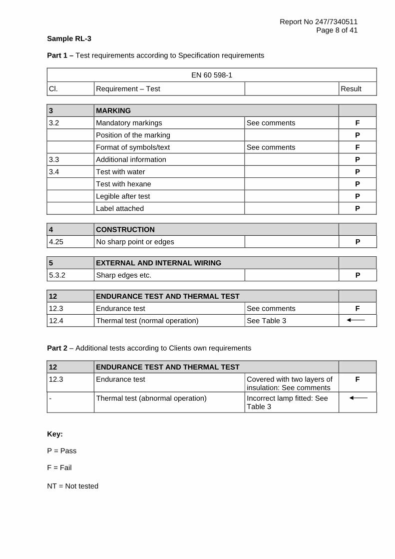
Page 8 of 41 Sample RL-3 Part 1 – Test requirements according to Specification requirements
EN 60 598-1
Cl. Requirement – Test Result 3 MARKING 3.2 Mandatory markings See comments F Position of the marking P Format of symbols/text See comments F 3.3 Additional information P 3.4 Test with water P Test with hexane P Legible after test P Label attached P 4 CONSTRUCTION 4.25 No sharp point or edges P 5 EXTERNAL AND INTERNAL WIRING 5.3.2 Sharp edges etc. P 12 ENDURANCE TEST AND THERMAL TEST 12.3 Endurance test See comments F 12.4 Thermal test (normal operation) See Table 3 Part 2 – Additional tests according to Clients own requirements 12 ENDURANCE TEST AND THERMAL TEST 12.3 Endurance test Covered with two layers of
insulation: See comments F
- Thermal test (abnormal operation) Incorrect lamp fitted: See Table 3
Key: P = Pass F = Fail NT = Not tested

Report No 247/7340511
Page 9 of 41
Table 3: Temperature measurements, thermal tests of Section 12 Type reference ............................................. : RL-3
Lamp used.................................................... : 12V 50W
Lamp control gear used................................ : Electronic transformer rated 240V (11.6V 60VA output)
Mounting position of luminaire...................... : Test recess
Supply wattage (W) ...................................... : 52.7
Supply current (A) ........................................ : 0.208
Supply voltage (V) ........................................ : 254.7 Table: Measured temperatures corrected for ta = 25 °C:
Temperature (°C) of part Normal Abnormal
Test Limit Test Limit
Transformer case 52 85 - -
PVC cable at transformer input terminals 34 90 - -
Glass fibre insulated cable at transformer output
38 200 - -
Glass fibre insulated cable at terminal block
89 200 - -
Terminal block 91 # - -
Terminal block enclosure base 98 # - -
Glass fibre insulated cable at luminaire entry
123 200 - -
Luminaire top (metal) 125 - - -
Glass fibre insulated cable at lampholder 190 200 - -
Ceramic lampholder 246 - - -
Minimum distance from lighted objects: 0.5m
28 90 - -
Test recess above luminaire 89 90 - -
Notes
1) The sample was operated at 1.06 x the maximum rated input voltage of the transformer i.e. 1.06 x 240 = 254.4V~.
2) The voltage recorded above is the noted voltage at the time of measurement.
3) # - Plastic moulded component and therefore the material and applied thermal limit is
unknown
4) The abnormal test was not conducted as a non-aluminium reflector lamp was fitted during the normal thermal test

Report No 247/7340511
Page 10 of 41 Sample RL- 4 Part 1 – Test requirements according to Specification requirements
EN 60 598-1
Cl. Requirement – Test Result 3 MARKING 3.2 Mandatory markings See comments F Position of the marking P Format of symbols/text P 3.3 Additional information P 3.4 Test with water See comments F Test with hexane See comments NT Legible after test See comments F Label attached P 4 CONSTRUCTION 4.25 No sharp point or edges P 5 EXTERNAL AND INTERNAL WIRING 5.3.2 Sharp edges etc. P 12 ENDURANCE TEST AND THERMAL TEST 12.3 Endurance test P 12.4 Thermal test (normal operation) See Table 4 Part 2 – Additional tests according to Clients own requirements 12 ENDURANCE TEST AND THERMAL TEST 12.3 Endurance test Covered with two layers of
insulation NT
- Thermal test (abnormal operation) Incorrect lamp fitted: See Table 4
Key: P = Pass F = Fail NT = Not tested

Report No 247/7340511
Page 11 of 41
Table 4: Temperature measurements, thermal tests of Section 12 Type reference ............................................. : RL-4
Lamp used.................................................... : 12V 50W
Lamp control gear used................................ : Electronic transformer rated 240V (11.5V 10-60W output)
Mounting position of luminaire...................... : Test recess
Supply wattage (W) ...................................... : 53.4
Supply current (A) ........................................ : 0.213
Supply voltage (V) ........................................ : 252.8 Table: Measured temperatures corrected for ta = 25 °C:
Temperature (°C) of part Normal Abnormal
Test Limit Test Limit
PVC cable at transformer input terminals 52 90 62 90
Transformer case 64 70 74 70*
Glass fibre insulated cable at transformer output
58 200 69 200
Plug and socket 61 # 74 #
Silicone insulated cable at luminaire entry
93 200 112 200
Rubber boot: Top 86 ** 110 **
Rubber boot: Base 88 ** 143 **
Silicone insulated wiring at lampholder 138 200 215 200
Ceramic lampholder 142 - 213 -
Minimum distance from lighted objects: 0.5m
45 90 32 90
Test recess above luminaire 67 90 90 90
Notes
1) The sample was operated at 1.06 x the maximum rated input voltage of the transformer i.e. 1.06 x 240 = 254.4V~.
2) The voltage recorded above is the noted voltage at the time of measurement.
3) # - Plastic moulded component and therefore the material and applied thermal limit is
unknown
4) The abnormal test is with a non-aluminium reflector lamp fitted
5) * - The Specification states that the applied temperature limit shall be considered with regard to a +5°C tolerance
6) ** - Type of rubber not known and therefore limit cannot be applied
7) The transformer supplied with the product for test failed after the completion of the
thermal endurance test. A commercially available transformer was therefore used to enable the tests to continue.

Report No 247/7340511
Page 12 of 41 Sample RL-5 Part 1 – Test requirements according to Specification requirements
EN 60 598-1
Cl. Requirement – Test Result 3 MARKING 3.2 Mandatory markings See comments Position of the marking P Format of symbols/text See comments F 3.3 Additional information See comments 3.4 Test with water P Test with hexane P Legible after test P Label attached P 4 CONSTRUCTION 4.25 No sharp point or edges P 5 EXTERNAL AND INTERNAL WIRING 5.3.2 Sharp edges etc. P 12 ENDURANCE TEST AND THERMAL TEST 12.3 Endurance test See comments F 12.4 Thermal test (normal operation) See Table 5 Part 2 – Additional tests according to Clients own requirements 12 ENDURANCE TEST AND THERMAL TEST 12.3 Endurance test Covered with two layers of
insulation P
- Thermal test (abnormal operation) Incorrect lamp fitted: See Table 5
Key: P = Pass F = Fail NT = Not tested

Report No 247/7340511
Page 13 of 41
Table 5: Temperature measurements, thermal tests of Section 12 Type reference ............................................. : RL-5
Lamp used.................................................... : 240V 50W
Lamp control gear used................................ : Not applicable
Mounting position of luminaire...................... : Test recess
Supply wattage (W) ...................................... : 52.5
Supply current (A) ........................................ : 0.224
Supply voltage (V) ........................................ : 237.3 Table: Measured temperatures corrected for ta = 25 °C:
Temperature (°C) of part Normal Abnormal
Test Limit Test Limit
Supply cable in cord restraint 77 75* - -
Neutral supply wire insulation at terminal block
84 90 - -
Terminal block 85 # - -
Terminal enclosure cover 75 # - -
Glass fibre insulated cable at entry into luminaire enclosure
106 200 - -
Top of luminaire enclosure 76 - - -
Internal wiring at lampholder 189 250 - -
Ceramic lampholder 230 - - -
Front bezel (metal) 114 - - -
Mounting surface: Luminaire hole 111 90 - -
Minimum distance form lighted objects: 0.5m
40 90 - -
Test recess above luminaire 78 90 - -
Notes
1) The sample was operated at 1.05 x the lamp rated wattage 2) The voltage recorded above is the noted voltage at the time of measurement.
3) # - Plastic moulded component and therefore the material and applied thermal limit is
unknown
4) The abnormal test was not applicable to this product type
5) * - The Specification states that the applied temperature limit shall be considered with regard to a +5°C tolerance

Report No 247/7340511
Page 14 of 41 Sample RL-6 Part 1 – Test requirements according to Specification requirements
EN 60 598-1
Cl. Requirement – Test Result 3 MARKING 3.2 Mandatory markings See comments F Position of the marking P Format of symbols/text See comments F 3.3 Additional information P 3.4 Test with water P Test with hexane P Legible after test P Label attached P 4 CONSTRUCTION 4.25 No sharp point or edges P 5 EXTERNAL AND INTERNAL WIRING 5.3.2 Sharp edges etc. P 12 ENDURANCE TEST AND THERMAL TEST 12.3 Endurance test P 12.4 Thermal test (normal operation) See Table 6 Part 2 – Additional tests according to Clients own requirements 12 ENDURANCE TEST AND THERMAL TEST 12.3 Endurance test Covered with two layers of
insulation P
- Thermal test (abnormal operation) Incorrect lamp fitted: See Table 6
Key: P = Pass F = Fail NT = Not tested
Report No 247/7340511
Page 15 of 41
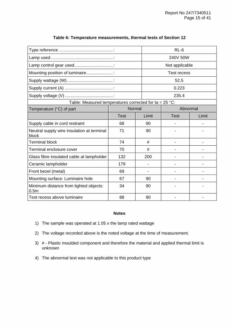
Table 6: Temperature measurements, thermal tests of Section 12 Type reference ............................................. : RL-6
Lamp used.................................................... : 240V 50W
Lamp control gear used................................ : Not applicable
Mounting position of luminaire...................... : Test recess
Supply wattage (W) ...................................... : 52.5
Supply current (A) ........................................ : 0.223
Supply voltage (V) ........................................ : 235.4 Table: Measured temperatures corrected for ta = 25 °C:
Temperature (°C) of part Normal Abnormal
Test Limit Test Limit
Supply cable in cord restraint 68 90 - -
Neutral supply wire insulation at terminal block
71 90 - -
Terminal block 74 # - -
Terminal enclosure cover 70 # - -
Glass fibre insulated cable at lampholder 132 200 - -
Ceramic lampholder 179 - - -
Front bezel (metal) 69 - - -
Mounting surface: Luminaire hole 67 90 - -
Minimum distance from lighted objects: 0.5m
34 90 - -
Test recess above luminaire 88 90 - -
Notes
1) The sample was operated at 1.05 x the lamp rated wattage 2) The voltage recorded above is the noted voltage at the time of measurement.
3) # - Plastic moulded component and therefore the material and applied thermal limit is
unknown
4) The abnormal test was not applicable to this product type

Report No 247/7340511
Page 16 of 41 Sample RL-7 Part 1 – Test requirements according to Specification requirements
EN 60 598-1
Cl. Requirement – Test Result 3 MARKING 3.2 Mandatory markings See comments F Position of the marking P Format of symbols/text P 3.3 Additional information P 3.4 Test with water P Test with hexane P Legible after test P Label attached P 4 CONSTRUCTION 4.25 No sharp point or edges P 5 EXTERNAL AND INTERNAL WIRING 5.3.2 Sharp edges etc. P 12 ENDURANCE TEST AND THERMAL TEST 12.3 Endurance test See comments F 12.4 Thermal test (normal operation) See Table 7 Part 2 – Additional tests according to Clients own requirements 12 ENDURANCE TEST AND THERMAL TEST 12.3 Endurance test Covered with two layers of
insulation: See comments F
- Thermal test (abnormal operation) Incorrect lamp fitted: See Table 7
Key: P = Pass F = Fail NT = Not tested
Report No 247/7340511
Page 17 of 41
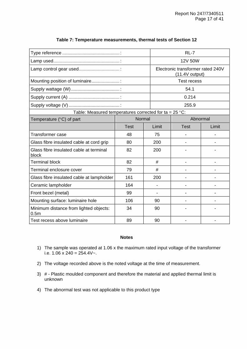
Table 7: Temperature measurements, thermal tests of Section 12 Type reference ............................................. : RL-7
Lamp used.................................................... : 12V 50W
Lamp control gear used................................ : Electronic transformer rated 240V (11.4V output)
Mounting position of luminaire...................... : Test recess
Supply wattage (W) ...................................... : 54.1
Supply current (A) ........................................ : 0.214
Supply voltage (V) ........................................ : 255.9 Table: Measured temperatures corrected for ta = 25 °C:
Temperature (°C) of part Normal Abnormal
Test Limit Test Limit
Transformer case 48 75 - -
Glass fibre insulated cable at cord grip 80 200 - -
Glass fibre insulated cable at terminal block
82 200 - -
Terminal block 82 # - -
Terminal enclosure cover 79 # - -
Glass fibre insulated cable at lampholder 161 200 - -
Ceramic lampholder 164 - - -
Front bezel (metal) 99 - - -
Mounting surface: luminaire hole 106 90 - -
Minimum distance from lighted objects: 0.5m
34 90 - -
Test recess above luminaire 89 90 - -
Notes
1) The sample was operated at 1.06 x the maximum rated input voltage of the transformer i.e. 1.06 x 240 = 254.4V~.
2) The voltage recorded above is the noted voltage at the time of measurement.
3) # - Plastic moulded component and therefore the material and applied thermal limit is
unknown
4) The abnormal test was not applicable to this product type

Report No 247/7340511
Page 18 of 41 Sample RL-8 Part 1 – Test requirements according to Specification requirements
EN 60 598-1
Cl. Requirement – Test Result 3 MARKING 3.2 Mandatory markings See comments F Position of the marking See comments F Format of symbols/text See comments F 3.3 Additional information P 3.4 Test with water NT Test with hexane NT Legible after test NT Label attached NT 4 CONSTRUCTION 4.25 No sharp point or edges P 5 EXTERNAL AND INTERNAL WIRING 5.3.2 Sharp edges etc. P 12 ENDURANCE TEST AND THERMAL TEST 12.3 Endurance test See comments F 12.4 Thermal test (normal operation) See Table 8 Part 2 – Additional tests according to Clients own requirements 12 ENDURANCE TEST AND THERMAL TEST 12.3 Endurance test Covered with two layers of
insulation: See comments F
- Thermal test (abnormal operation) Incorrect lamp fitted: See Table 8
Key: P = Pass F = Fail NT = Not tested
Report No 247/7340511
Page 19 of 41
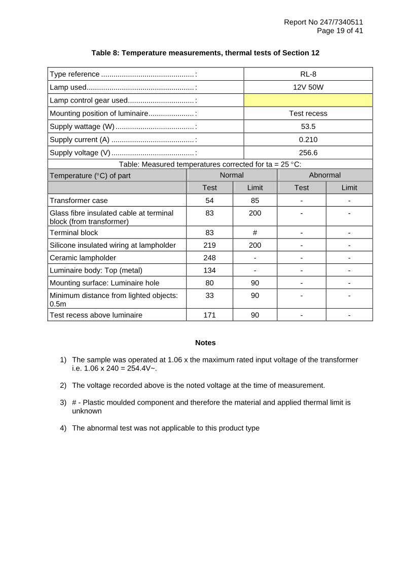
Table 8: Temperature measurements, thermal tests of Section 12 Type reference ............................................. : RL-8
Lamp used.................................................... : 12V 50W
Lamp control gear used................................ :
Mounting position of luminaire...................... : Test recess
Supply wattage (W) ...................................... : 53.5
Supply current (A) ........................................ : 0.210
Supply voltage (V) ........................................ : 256.6 Table: Measured temperatures corrected for ta = 25 °C:
Temperature (°C) of part Normal Abnormal
Test Limit Test Limit
Transformer case 54 85 - -
Glass fibre insulated cable at terminal block (from transformer)
83 200 - -
Terminal block 83 # - -
Silicone insulated wiring at lampholder 219 200 - -
Ceramic lampholder 248 - - -
Luminaire body: Top (metal) 134 - - -
Mounting surface: Luminaire hole 80 90 - -
Minimum distance from lighted objects: 0.5m
33 90 - -
Test recess above luminaire 171 90 - -
Notes
1) The sample was operated at 1.06 x the maximum rated input voltage of the transformer i.e. 1.06 x 240 = 254.4V~.
2) The voltage recorded above is the noted voltage at the time of measurement.
3) # - Plastic moulded component and therefore the material and applied thermal limit is
unknown
4) The abnormal test was not applicable to this product type

Report No 247/7340511
Page 20 of 41
COMMENTS SECTION
Sample No RL-1 Clause 3 .2 Marking on luminaires The assessment was made on the label attached to the luminaire body. However, this label was attached to the exterior surface of the body and would therefore not be seen once installed or during lamp replacement. Sub-Clause 3.2.1 Mark of origin The manufacturer’s name or trade mark was not shown on the label attached to the luminaire body. Sub-Clause 3.2.6 IP rating The product packaging indicated that the sample was an IP65 rated shower light. The main label did not contain this rating i.e. IP65, but had the old graphical symbols that related to the rating of IP55. The leaflet supplied with the product contained the symbol of a house and a symbol with an arrow pointing inside (indicating indoor use), with a rating of IP20 stated. This conflicts with the product packaging and marking. Sub-Clause 3.2.7 Model number or type reference The sample was not marked with the model number as shown on the product packaging. Sub-Clause 3.2.9 Luminaires not suitable for mounting on combustible surfaces The sample was not marked with the symbol that denotes that the symbol is unsuitable for mounting on combustible surfaces. However the leaflet provided with the product contained the previously used F Mark symbol with a top hat denoting that it could be mounted on combustible surfaces and covered with insulating material. Clause 3.3 Additional information Sub-Clause 3.3.10 Suitable for use indoors The Specification states that IP rated luminaires shall have a statement contained within the installation leaflet that they are suitable for use indoors and contain details of the ambient temperature of use. The leaflet supplied with the luminaire for test was relevant to a product rated IP20 ordinary and therefore contained no information relevant to an IP rated luminaire.

Report No 247/7340511
Page 21 of 41
COMMENTS SECTION
Sample No RL-1: Continued/… Additional thermal test – Luminaire covered with two layers of insulation In accordance with the Clients request, the sample was subjected to an additional thermal endurance test, when covered with two layers of insulation. This was deemed to be an abnormal mode of operation that ignored the installation instructions that advised that the luminaire should not be covered. The luminaire was operated in accordance with the guidance of Clause 12.3 of the Specification, in an ambient temperature of 35°C and when mounted in a test recess. The test recess was manufactured in accordance with the Specification requirements and taking into account the installation instructions. Under the conditions specified it was noted during the test that the sample cycled on and off, due to the thermal protection device fitted into the electronic transformer. However, the sample showed no signs of scorching or deterioration that would affect safety at the completion of the test period.
Report No 247/7340511
Page 22 of 41
COMMENTS SECTION
Sample No RL-2 Clause 3.2 Marking on luminaires The luminaire was noted to have been marked with the required Specification marking details. However, to ensure legibility all text, numerals and symbols shall be subjected to the minimum size requirements. The text and numerals of the main product label were noted to be less than the 2mm minimum limit, having been measured at 1.7mm. Sub-Clause 3.2.9 Luminaires not suitable for mounting on combustible surfaces The luminaire was marked with the previously used F Mark symbol to denote that it is suitable for use on normally flammable surfaces. This symbol is no longer required as the product only needs to be marked when the luminaire is not suitable for direct mounting on normally flammable surfaces. Sub-Clause 3.2.21 Luminaires not suitable for covering with insulating material The installation leaflet supplied with the luminaire submitted contained a warning notice that the luminaire shall not be covered with insulating material. The Specification requires the relevant symbol to be shown on the luminaire marking details with an explanation of the meaning stated within the leaflet and /or on the luminaire.
Additional thermal test with an abnormal lamp condition applied
The sample was subjected to a normal thermal test, but with a non-aluminium lamp fitted. Under this test condition the following was noted.
o The test recess mounting hole for the luminaire limit of 90°C was exceeded o The glass fibre sleeved wiring at the lampholder exceeded the 200°C limit specified, but
was within the 5°C tolerance allowed
o The test recess above the luminaire was recorded at 91°C with the Specification limit being 90°C, but was within the 5°C tolerance allowed

Report No 247/7340511
Page 23 of 41
COMMENTS SECTION
Sample No RL-3 Clause 3 .2 Marking on luminaires The assessment was made on the labels attached to the luminaire body, with one label on the outside and one on the inside. Sub-Clause 3.2.5 Class III symbol The sample was not marked with the Class III symbol as required for a 12V design of luminaire. Sub-Clause 3.2.9 Luminaires not suitable for mounting on combustible surfaces The luminaire was marked with the previously used F Mark symbol to denote that it is suitable for use on normally flammable surfaces. This symbol is no longer required as the product only needs to be marked when the luminaire is not suitable for direct mounting on normally flammable surfaces. Sub-Clause 3.2.21 Luminaires not suitable for covering with insulating material The installation leaflet supplied with the luminaire submitted contained a warning notice that the luminaire shall not be covered with insulating material. The Specification requires the relevant symbol to be shown on the luminaire marking details with an explanation of the meaning stated within the leaflet and /or on the luminaire. Clause 12.3 Thermal endurance test The luminaire was operated in accordance with the Specification requirements for a period of ten days, in an ambient temperature of 35°C and when mounted in a test recess. The test recess was manufactured in accordance with the Specification requirements and taking into account the installation instructions. The inspection after test revealed the following (see also photograph below):
o Discolouration / browning due to heat of the label o Curling of the label making the content unreadable
o Discoloration of the internal white painted surface of the luminaire enclosure
Report No 247/7340511
Page 24 of 41
COMMENTS SECTION
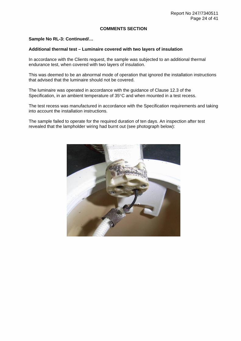
Sample No RL-3: Continued/… Additional thermal test – Luminaire covered with two layers of insulation In accordance with the Clients request, the sample was subjected to an additional thermal endurance test, when covered with two layers of insulation. This was deemed to be an abnormal mode of operation that ignored the installation instructions that advised that the luminaire should not be covered. The luminaire was operated in accordance with the guidance of Clause 12.3 of the Specification, in an ambient temperature of 35°C and when mounted in a test recess. The test recess was manufactured in accordance with the Specification requirements and taking into account the installation instructions. The sample failed to operate for the required duration of ten days. An inspection after test revealed that the lampholder wiring had burnt out (see photograph below):

Report No 247/7340511
Page 25 of 41
COMMENTS SECTION
Sample No RL-4 Clause 3 .2 Marking on luminaires The assessment was made on the labels attached to the luminaire, with one label on the lampholder wiring and one on the rubber boot. Sub-Clause 3.2.7 Model number or type reference The sample was not marked with the model number as shown on the product packaging. Sub-Clause 3.2.9 Luminaires not suitable for mounting on combustible surfaces The luminaire was marked with the previously used F Mark symbol to denote that it is suitable for use on normally flammable surfaces and being covered with insulating material. This symbol is no longer required as the product only needs to be marked when the luminaire is not suitable for direct mounting on normally flammable surfaces. Clause 3.4 Durability of marking The Specification requires all mandatory marking details to be shown in such a manner that it durable and shall be checked by the application of water and spirit soaked soft cloths for a duration of 15 seconds each. The water soaked cloth was applied for the required duration of 15 seconds and it was noted that the paper fibres had begun to break up rendering the marking unreadable. See photograph below. Due to the above stated failure the spirit soaked cloth was not applied.
Additional thermal test with an abnormal lamp condition applied
The sample was subjected to a normal thermal test, but with a non-aluminium lamp fitted. Under this test condition the following was noted.
o The silicone insulated wiring at the lampholder exceeded the 200°C limit specified
o The test recess above the luminaire was recorded at 90°C with the Specification limit
being 90°C

Report No 247/7340511
Page 26 of 41
COMMENTS SECTION
Sample No RL-5 Clause 3 .2 Marking on luminaires The assessment was made on the labels attached to the luminaire body, with one label on the outside and one on the inside. To ensure legibility all text, numerals and symbols shall be subjected to the minimum size requirements. The text and numerals of the main product label were noted to be 2mm with the Specification limit also being 2mm minimum. The Class II symbol i.e. square within a square was noted to have a outer edge dimension of 4.2mm with a limit of 5mm. Sub-Clause 3.2.2 Rated supply voltage The label attached to the outside of the luminaire stated the luminaire rated voltage as being 230V AC, whereas the label on the inner surface stated it as being 240V AC. The associated installation leaflet stated the rated voltage as being 230/240V 50Hz. Sub-Clause 3.2.3 Rated ambient temperature of use (ta) The sample submitted was not marked with a rated ambient temperature of use (ta) and as such all tests were applied based upon the normal rating of 25°C. However, the installation leaflet supplied with the luminaire submitted states the luminaire temperature range as being: -20° to +40°C. Sub-Clause 3.2.9 Luminaires not suitable for mounting on combustible surfaces The luminaire was marked with the previously used F Mark symbol to denote that it is suitable for use on normally flammable surfaces and being covered with insulating material. This symbol is no longer required as the product only needs to be marked when the luminaire is not suitable for direct mounting on normally flammable surfaces. Sub-Clause 3.2.21 Luminaires not suitable for covering with insulating material The installation leaflet supplied with the luminaire submitted contained a warning notice that the luminaire shall not be covered with insulating material. The Specification requires the relevant symbol to be shown on the luminaire marking details with an explanation of the meaning stated within the leaflet and /or on the luminaire.

Report No 247/7340511
Page 27 of 41
COMMENTS SECTION
Sample No RL-5: Continued/… Clause 12.3 Thermal endurance test The luminaire was operated in accordance with the Specification requirements for a period of ten days, in an ambient temperature of 35°C and when mounted in a test recess. The test recess was manufactured in accordance with the Specification requirements and taking into account the installation instructions. The inspection after test revealed the following (see also photograph below):
o Curling of the label making the content unreadable
Clause 12.4 Thermal test (normal operation) The PVC supply cable in the cord restraint was noted to have achieved a temperature of 77°C with an applied Specification limit of 75°C. However, the temperature recorded was within the +5°C tolerance allowed by the Specification. The temperature of the test recess surface hole through which the luminaire is mounted was noted to reach a temperature of 111°C, with an applied Specification limit of 90°C.

Report No 247/7340511
Page 28 of 41
COMMENTS SECTION
Sample No RL-6 Clause 3 .2 Marking on luminaires The assessment was made on the label attached to the luminaire arm to which the supply terminal block and enclosure are mounted. To ensure legibility all text, numerals and symbols shall be subjected to the minimum size requirements. The text and numerals of the main product label were noted to be 2.1/2.2mm with the Specification limit being 2mm minimum. The Class II symbol i.e. square within a square was noted to have a outer edge dimension of 3.7mm with a limit of 5mm. Sub-Clause 3.2.9 Luminaires not suitable for mounting on combustible surfaces The luminaire was marked with the previously used F Mark symbol to denote that it is suitable for use on normally flammable surfaces and being covered with insulating material. This symbol is no longer required as the product only needs to be marked when the luminaire is not suitable for direct mounting on normally flammable surfaces. Sub-Clause 3.2.21 Luminaires not suitable for covering with insulating material The installation leaflet supplied with the luminaire submitted contained a warning notice that the luminaire shall not be covered with insulating material. The Specification requires the relevant symbol to be shown on the luminaire marking details with an explanation of the meaning stated within the leaflet and /or on the luminaire.

Report No 247/7340511
Page 29 of 41
COMMENTS SECTION
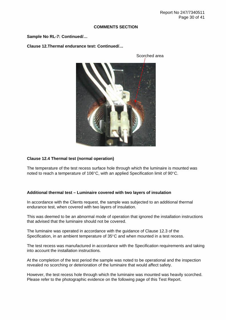
Sample No RL-7 Clause 3 .2 Marking on luminaires The assessment was made on the label attached to the luminaire body and to the luminaire arm to which the supply terminal block and enclosure are mounted. Sub-Clause 3.2.8 Rated wattage The luminaire was noted to have conflicting marking with regard to the rated wattage. The main product label was noted to show the wattage as being 50W with a second label showing the F Mark symbol with 35W being marked adjacent to this symbol. Attention is drawn to following comment on the use of the F Mark symbol. Sub-Clause 3.2.9 Luminaires not suitable for mounting on combustible surfaces The luminaire was marked with the previously used F Mark symbol to denote that it is suitable for use on normally flammable surfaces and being covered with insulating material. This symbol is no longer required as the product only needs to be marked when the luminaire is not suitable for direct mounting on normally flammable surfaces. Sub-Clause 3.2.21 Luminaires not suitable for covering with insulating material The installation leaflet supplied with the luminaire submitted contained a warning notice that the luminaire shall not be covered with insulating material. The Specification requires the relevant symbol to be shown on the luminaire marking details with an explanation of the meaning stated within the leaflet and /or on the luminaire. Clause 12.3 Thermal endurance test The luminaire was operated in accordance with the Specification requirements for a period of ten days, in an ambient temperature of 35°C and when mounted in a test recess. The test recess was manufactured in accordance with the Specification requirements and taking into account the installation instructions. The inspection after test revealed the following (see also photograph on following page):
o Overheating of the test recess hole through which the luminaire is mounted indicated by signs of scorching of the wood surface
Report No 247/7340511
Page 30 of 41
COMMENTS SECTION
Sample No RL-7: Continued/… Clause 12.Thermal endurance test: Continued/… Scorched area
Clause 12.4 Thermal test (normal operation) The temperature of the test recess surface hole through which the luminaire is mounted was noted to reach a temperature of 106°C, with an applied Specification limit of 90°C. Additional thermal test – Luminaire covered with two layers of insulation In accordance with the Clients request, the sample was subjected to an additional thermal endurance test, when covered with two layers of insulation. This was deemed to be an abnormal mode of operation that ignored the installation instructions that advised that the luminaire should not be covered. The luminaire was operated in accordance with the guidance of Clause 12.3 of the Specification, in an ambient temperature of 35°C and when mounted in a test recess. The test recess was manufactured in accordance with the Specification requirements and taking into account the installation instructions. At the completion of the test period the sample was noted to be operational and the inspection revealed no scorching or deterioration of the luminaire that would affect safety. However, the test recess hole through which the luminaire was mounted was heavily scorched. Please refer to the photographic evidence on the following page of this Test Report.

Report No 247/7340511
Page 31 of 41
COMMENTS SECTION
Sample No RL-7: Continued/… Additional thermal test – Luminaire covered with two layers of insulation: Continued/… Photographic evidence of test recess after test
Scorched area
Scorched area with luminaire removed

Report No 247/7340511
Page 32 of 41
COMMENTS SECTION
Sample No RL-8 Clause 3.2 Marking on luminaires The relevant Specification requirements could not be assessed on the sample submitted as no labels or other forms of marking had been provided. When marked, the following information is required to be shown:
o Sub-Clause 3.2.1 Mark of origin o Sub-Clause 3.2.2 Rated supply voltage o Sub-Clause 3.2.3 Rated ambient temperature of use (if other than 25°C) o Sub-Clause 3.2.5 Class III symbol o Sub-Clause 3.2.7 Model number or type reference o Sub-Clause 3.2.8 Rated lamp wattage o Sub-Clause 3.2.10 Special lamp information o Sub-Clause 3.2.13 Minimum distance from lighted objects symbol
Sub-Clause 3.2.21 Luminaires not suitable for covering with insulating material The installation leaflet supplied with the luminaire submitted contained a warning notice that the luminaire shall not be covered with insulating material. The Specification requires the relevant symbol to be shown on the luminaire marking details with an explanation of the meaning stated within the leaflet and /or on the luminaire. Clause 12.3 Thermal endurance test The luminaire was operated in accordance with the Specification requirements for a period of ten days, in an ambient temperature of 35°C and when mounted in a test recess. The test recess was manufactured in accordance with the Specification requirements and taking into account the installation instructions. The inspection after test revealed the following (see also photograph below):
o Overheating of the test recess above the luminaire indicated by signs of scorching of the wood surface

Report No 247/7340511
Page 33 of 41
COMMENTS SECTION
Sample No RL-8: Continued/… Clause 12.4 Thermal test (normal operation) The silicone insulated lampholder wiring was noted to have achieved a temperature of 219°C with an applied Specification limit of 200°C. The temperature of the test recess surface above the luminaire was noted to reach a temperature of 171°C, with an applied Specification limit of 90°C. Additional thermal test – Luminaire covered with two layers of insulation In accordance with the Clients request, the sample was subjected to an additional thermal endurance test, when covered with two layers of insulation. This was deemed to be an abnormal mode of operation that ignored the installation instructions that advised that the luminaire should not be covered. The luminaire was operated in accordance with the guidance of Clause 12.3 of the Specification, in an ambient temperature of 35°C and when mounted in a test recess. The test recess was manufactured in accordance with the Specification requirements and taking into account the installation instructions. During the test period the sample was noted to be non-operational. Further inspection revealed that the lamp had failed. The lamp was replaced and the test continued to the required period of operation. At the completion of the test the sample was noted to be operational and the inspection revealed no scorching or deterioration of the luminaire that would affect safety. However, the test recess above the luminaire was heavily scorched, as shown by the following photograph:

Report No 247/7340511
Page 34 of 41
PHOTOGRAPHIC EVIDENCE OF SAMPLES SUBMITTED
Sample No RL-1

Report No 247/7340511
Page 35 of 41
PHOTOGRAPHIC EVIDENCE OF SAMPLES SUBMITTED
Sample No RL-2

Report No 247/7340511
Page 36 of 41
PHOTOGRAPHIC EVIDENCE OF SAMPLES SUBMITTED
Sample No RL-3

Report No 247/7340511
Page 37 of 41
PHOTOGRAPHIC EVIDENCE OF SAMPLES SUBMITTED
Sample No RL-4

Report No 247/7340511
Page 38 of 41
PHOTOGRAPHIC EVIDENCE OF SAMPLES SUBMITTED
Sample No RL-5
Report No 247/7340511
Page 39 of 41
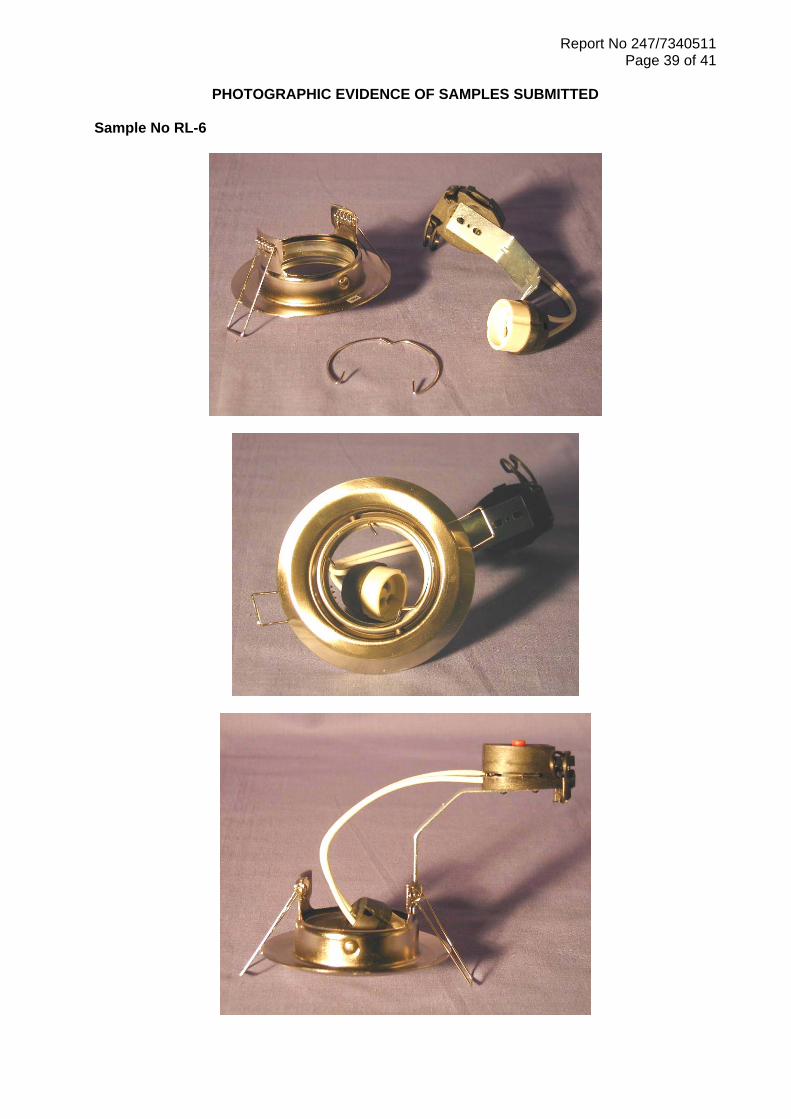
PHOTOGRAPHIC EVIDENCE OF SAMPLES SUBMITTED
Sample No RL-6

Report No 247/7340511
Page 40 of 41
PHOTOGRAPHIC EVIDENCE OF SAMPLES SUBMITTED
Sample No RL-7

Report No 247/7340511
Page 41 of 41
PHOTOGRAPHIC EVIDENCE OF SAMPLES SUBMITTED
Sample No RL-8