Embed Size (px)
Citation preview

(Autotronics)
BEE2922Engineering Lab IV

Basic Autotronic Teaching Outline
• The student will learn how to design an automatic controller using the combination of electronic circuit,switch ,relay, timer,sensor,ac/dc
Course Outcome For Autotronics
1. Recognize the function of electrical and electronic switches, relays and sensors
2. Identify the function and operate various types of relay, switches and transistors
3. Design and demonstrate applied electrical and electronic circuit.

Syllabus1.0 Introduction
1.1 Introduction to Autotronics1.1.1 course information 1.1.2 course description 1.1.3 safety- Discipline and attire
2.0 Power source 2.1 AC source2.2 DC source
2.2.1 Battery overview
3.0 Electrical Switches3.1 Switch selection –
3.1.1 contact3.1.2 rating
3.2 Operation method3.3 Symbols

Syllibus (cont….)4.0 Diode
4.1 Diode characteristics4.2 Diode type and applications
5.0 Transistor 5.1 transistor characteristics5.2 Transistor type and applications
6.0 Relays 6.1 basic concept of relay6.2 relay construction6.3 type of relay6.4 relay application-holding circuit, flip-flop, forward-reverse circuit

Syllibus (cont….)
7.0 Relay with timer7.1 basic concept7.2 construction7.3 application
8.0 Sensors8.1 type of sensors- NPN,PNP
9.0 Project

Course DescriptionIn this AUTOTRONICS course, the student will learn how to design an automatic controller using combination of electronic circuit, switches ,relays, timers, sensors, AC/DC motors, inverters and PLC.

What is Autotronic?
• generally- in modern engineering, word “autotronic”, is show the electronic concept in automobile technology.
• combination of electrical and electronic switches concept.
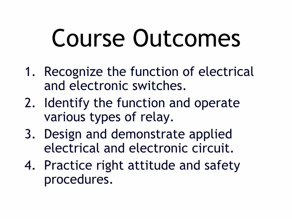
Course Outcomes1. Recognize the function of electrical
and electronic switches.2. Identify the function and operate
various types of relay.3. Design and demonstrate applied
electrical and electronic circuit.4. Practice right attitude and safety
procedures.

Mark Distribution• Practical reports (Exercises) = 5% • Quizzes = 5%• Practical Assessment I = 10%• Practical Assessment II = 10%• Practical Assessment III = 10%• Final Project + Report = 10%
Total (Finalised) = 50%! Other 50% is provided for Industrial Wiring

Course Syllabus• Introduction• Safety
- Discipline and attitude- General Safety
• Power Source - AC/DC Source• Battery
- type of Battery- Battery overview supply- Load Circuit- charging and overcharging- battery maintenance

• Electrical Switches- Switch selection –rating/ contact- type of switches – SPDT/DPDT- Contact –POLE, THROW, WAY,
MOMENTARY, OPEN, CLOSE, - NC, NO and etc.
• Rating-maximum voltage and current.

Teaching Outline

POWER SUPPLY

BASIC ELEC. LOOP

DC CURRENT
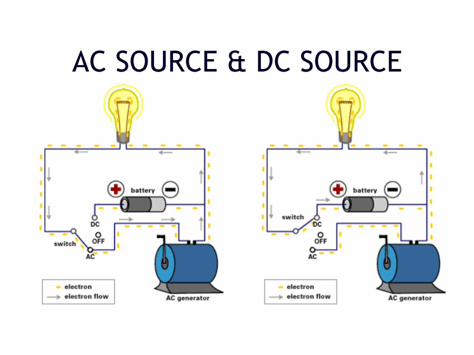
AC SOURCE & DC SOURCE

SWITCH
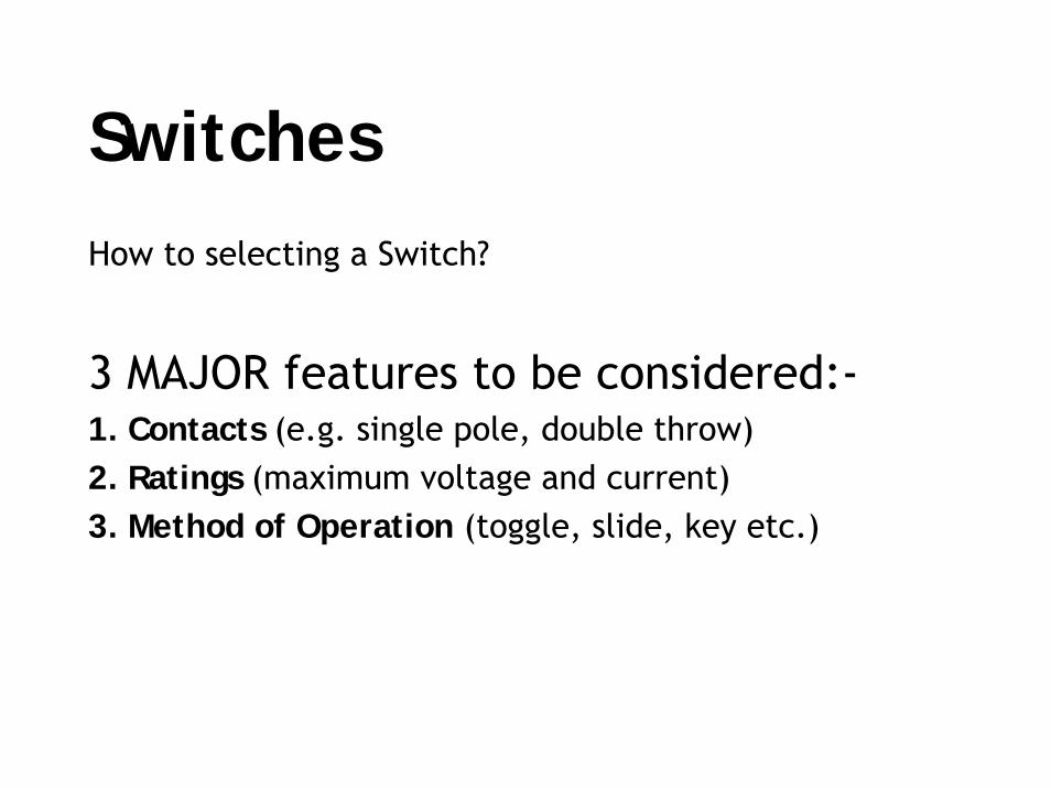
SwitchesHow to selecting a Switch?
3 MAJOR features to be considered:-1. Contacts (e.g. single pole, double throw) 2. Ratings (maximum voltage and current) 3. Method of Operation (toggle, slide, key etc.)

1. Switch Contacts
Several terms are used to describe switch contacts:
Pole - number of switch contact sets. Throw - number of conducting positions, single or double. Way - number of conducting positions, three or more. Momentary - switch returns to its normal position when released. Open - off position, contacts not conducting. Closed - on position, contacts conducting, there may be several on positions. N.O – (Normally Open) contacts open in normal conditionN.C - (Normally Close) contacts closed in normal condition

2. Switch RatingRated with a maximum voltage and currentAC value are higher – arc less likely to formLow voltage electronics-need to check current rating.The maximum current is less for inductive loads (coils and motors) because they cause more sparking at the contacts when switched off.

3. Method of operation
• Toggle switch
• Rotary switch
• Rocker switch
• Leaf switch
• Slide switch
• Push Button

Switch & symbols
Type of Switch SymbolsToggle switch,SPST, (N.O)
Toggle switch,SPST, (N.C)
Momentary switch/push button(ON)-OFF / Push-to-make, SPST
Momentary switch/push button(ON)-OFF / Push-to-break, SPST
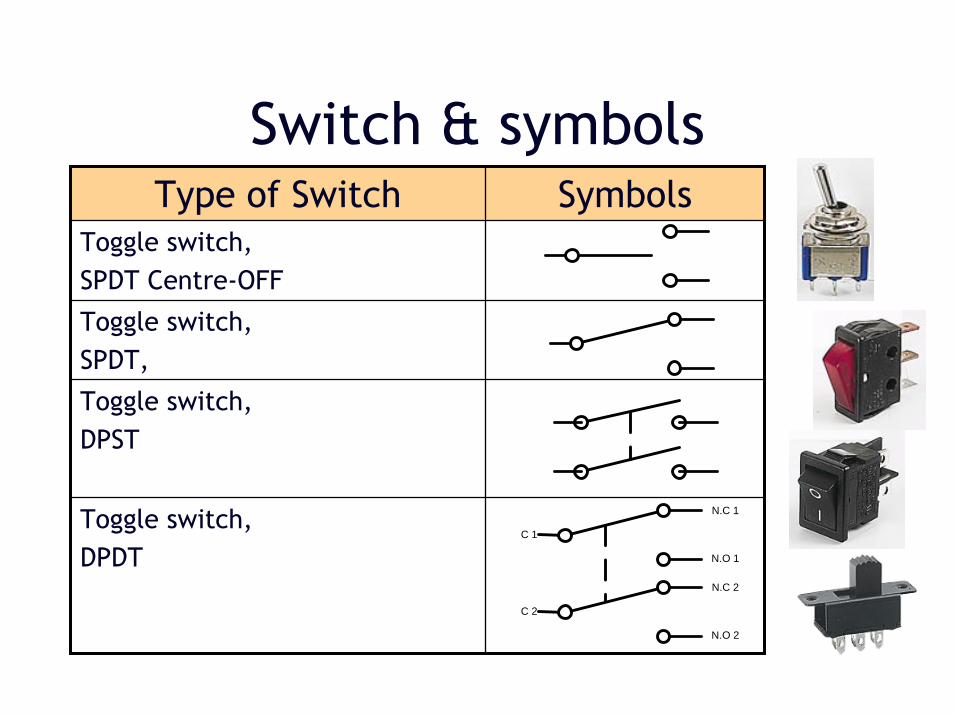
Switch & symbolsType of Switch Symbols
Toggle switch,SPDT Centre-OFF
Toggle switch,SPDT,
Toggle switch,DPST
Toggle switch,DPDT N.O 1
N.C 1
C 1
N.O 2
N.C 2
C 2
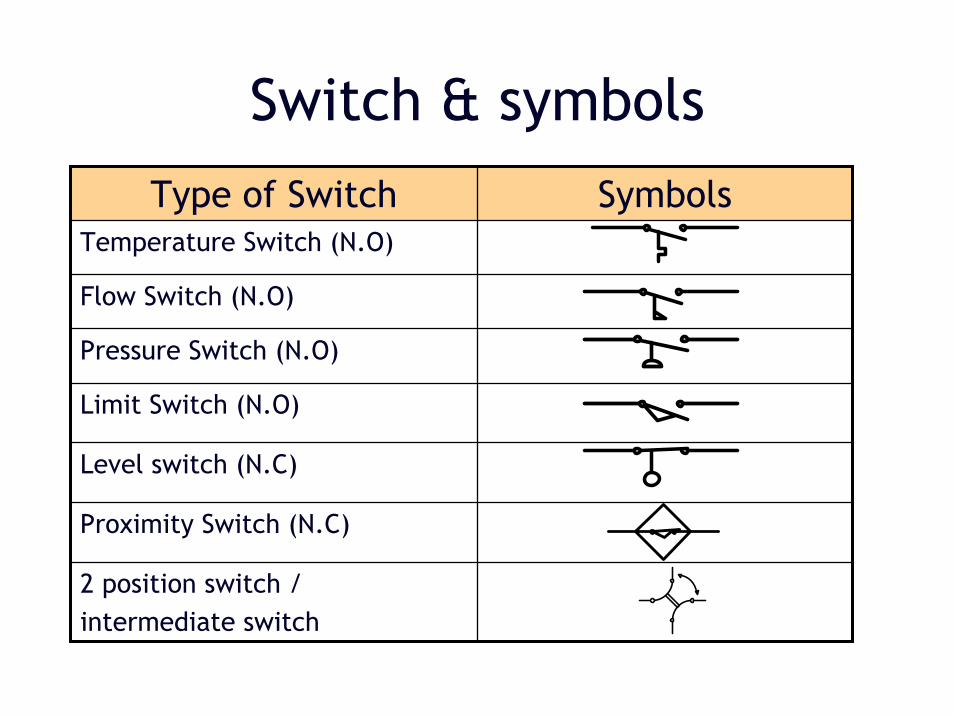
Switch & symbolsType of Switch Symbols
Temperature Switch (N.O)
Flow Switch (N.O)
Pressure Switch (N.O)
Limit Switch (N.O)
Level switch (N.C)
Proximity Switch (N.C)
2 position switch / intermediate switch

Switches in series• If several on-off switches are connected in series they must
all be closed (on) to complete the circuit.
• The diagram shows a simple circuit with two switches connected in series to control a lamp.
• Switch S1 AND Switch S2 must be closed to light the lamp.

Switches in Parallel• If several on-off switches are connected in parallel only one
needs to be closed (on) to complete the circuit.
• The diagram shows a simple circuit with two switches connected in parallel to control a lamp.
• Switch S1 OR Switch S2 (or both of them) must be closed to light the lamp.

Exercise
• 3 switches used to control (on/off) 1 set of lamp.– One walk-way corridor. – Switch at begin, middle & end of corridor. – On/Off a set of lamp with any of the
switch.

Solution 1a
S1S2
LAMP
ACL1 N
S3

Solution 2a
S1S2
LAMP
ACL1 N
S3

Homework
• 4 switches used to control (on/off) 1 set of lamp.– One hall has 4 doors. – Door located at each side. – Beside each door has a switch to control a
set of lamp. – On/Off a set of lamp with any of the
switch.

Solution Homework
S1S2
LAMP
ACL1 N
S3 S4

RELAY

RELAY
• A relay is an electrically operated switch.
• Consist 2 part:-– Coil– Contact
• Contact will activated when the coil is energize.
• Relays allow one circuit to switch a second circuit which can be completely separate from the first.

RELAY• The coil of a relay passes a relatively large current.
• But, can be as much as 100mA for relays designed to operate from lower voltages.
• Most ICs (chips) cannot provide this current and a transistor is usually used to amplify the small IC current to the larger value required for the relay coil.
• What is “COMM” , “NO” and “NC”???

Choosing Relay
• Physical size and pin arrangementMake sure the dimensions and pin arrangement are suitable for your project.
• Coil voltageThe relay's coil voltage rating and resistance must suit the circuit powering the relay coil. Many relay have a coil rated for a 12V supply but 5V and 24V relays are also readily available. Some relays operate perfectly well with a supply voltage which is a little lower than their rated value.

Choosing Relay
• Coil resistanceThe circuit must be able to supply the current required by the relay coil.
– Relay coil current = supply voltage/coil resistance
For example: A 12V supply relay with a coil resistance of 400Ω passes a current of 30mA. This is OK for a 555 timer IC (maximum output current 200mA), but it is too much for most ICs and they will require a transistor to amplify the current.
Choosing Relay
Switch/contact ratings (voltage and current)The relay's switch contacts must be suitable for the circuit they are to control. Note that the voltage rating is usually higher for AC, for example: "5A at 24V DC or 125V AC".
Switch contact arrangement (SPDT, DPDT etc)Most relays are SPDT or DPDT which are often described as "single pole changeover" (SPCO) or "double pole changeover" (DPCO).

Able to switch AC and DC, transistors can only switch DC.
Can switch high voltages, transistors cannot.
Better choice for switching large currents (> 5A).
Switch many contacts at once.
Advantages of relays
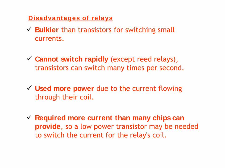
Bulkier than transistors for switching small currents.
Cannot switch rapidly (except reed relays), transistors can switch many times per second.
Used more power due to the current flowing through their coil.
Required more current than many chips can provide, so a low power transistor may be needed to switch the current for the relay's coil.
Disadvantages of relays

Relay operation
+ 24V
+ 24V
0V
0V
+ 24V
+ 24V
0V
0V
? ?
????
? ?
????
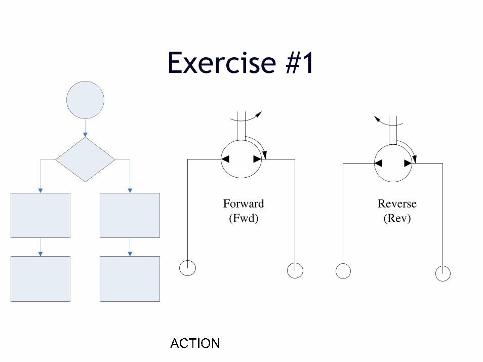
Exercise #1
Forward (Fwd)
Reverse (Rev)
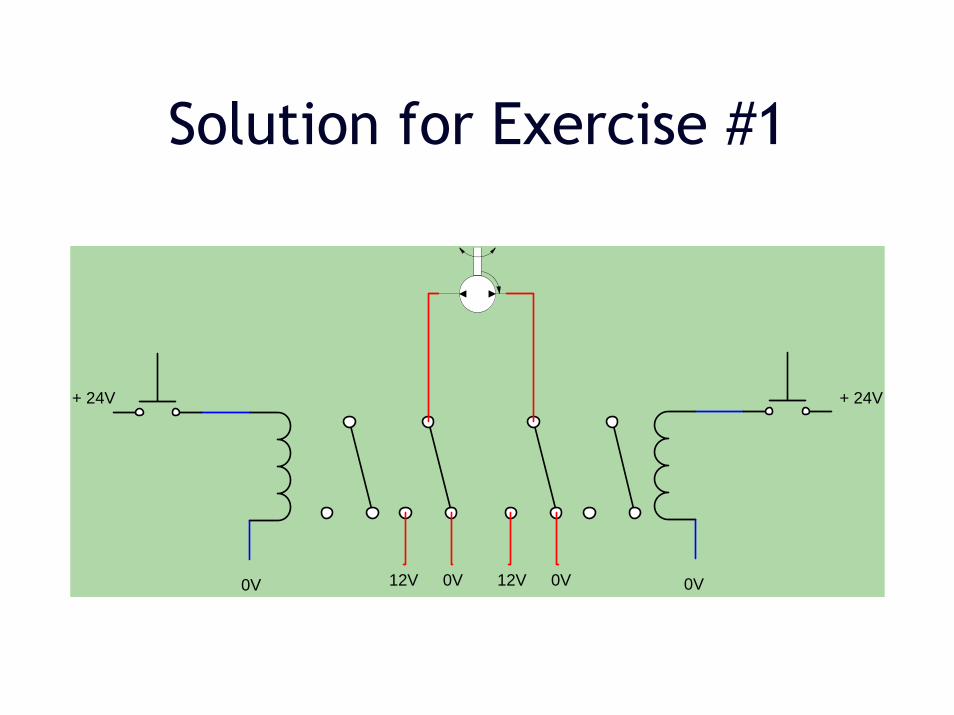
Solution for Exercise #1
+ 24V + 24V
0V 0V0V12V 0V12V

Relay - Holding circuit
+ 24V
+ 24V
0V
0V
+ 24V
+ 24V
0V
0V
+ 24V
+ 24V
0V
0V
1
2
Current can flows through these conductor
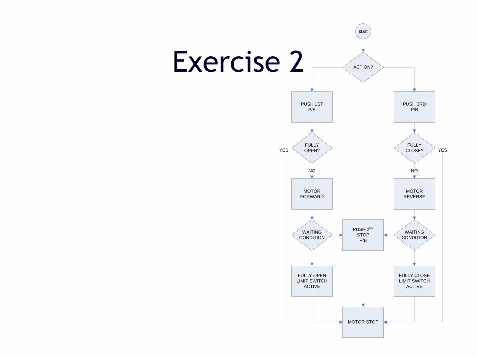
Exercise 2 ACTION?
start
PUSH 1ST P/B
PUSH 3RD P/B
MOTOR FORWARD
FULLY OPEN?
MOTOR REVERSE
FULLY CLOSE?
NONO
WAITING CONDITION
WAITING CONDITION
PUSH 2ND
STOP P/B
MOTOR STOP
FULLY CLOSE LIMIT SWITCH
ACTIVE
FULLY OPEN LIMIT SWITCH
ACTIVE
YESYES

Solution 2 – step 1 (stop by push button)
+ 24V+ 24V
0V 0V0V12V 0V12V
+ 24V

Solution 2 – step 2 (stop by limit switch)
+ 24V+ 24V
0V 0V0V12V 0V12V
+ 24V
FULLY CLOSEL/S
FULLY OPENL/S
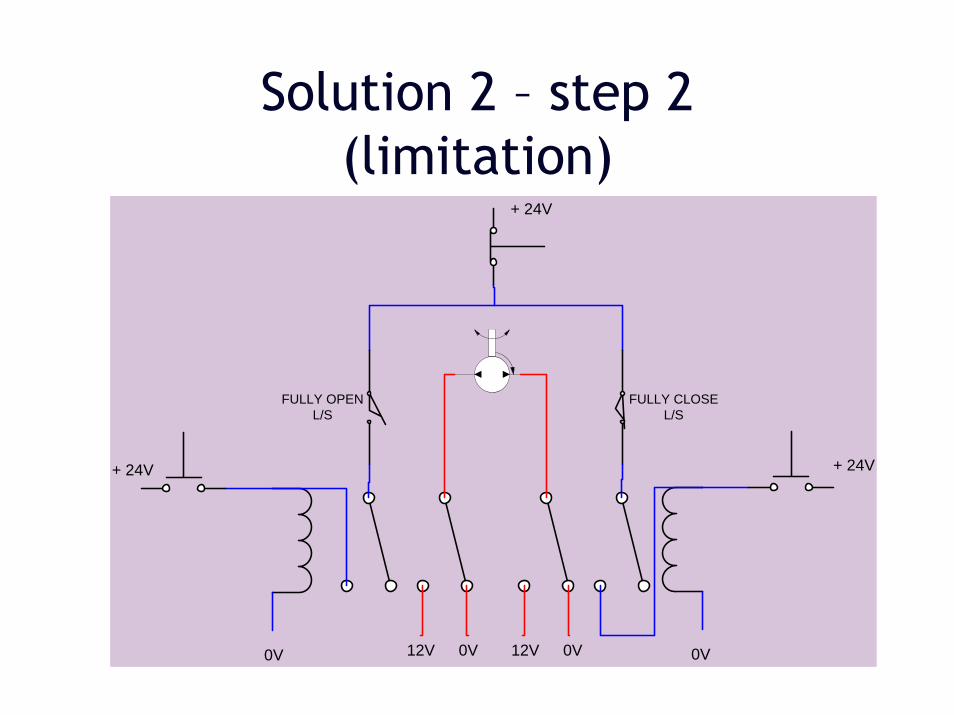
Solution 2 – step 2 (limitation)
0V 0V0V12V 0V12V
+ 24V
FULLY CLOSEL/S
FULLY OPENL/S
+ 24V+ 24V

Solution 2 – step 3 (Final touch up)
0V 0V0V12V 0V12V
+ 24V
FULLY CLOSEL/S
FULLY OPENL/S

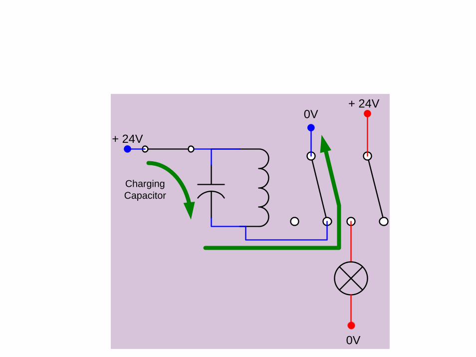
Relay – Flip-flop
• Need to added a capacitor to circuit.
• What that capacitor can do?– As a temporary battery.– Charge and discharge


Relay – Flip-flop
+ 24V
+ 24V
0V
0V
+ 24V
+ 24V
0V
0V
Charging Capacitor


+ 24V
+ 24V
0V
0V
CapacitorDischarging

Exercise 3start
System ON? <S/S 1>
Door open?<L/S 1>
Red Lamp BlinkBuzzer ON
Door Close?<L/S 1>
Reset by S/S 1
yes
Yes
Yes
No
No
No
Red Lamp STOP Blink
Buzzer OFF
Yes
No
S/S = Selector Switch
L/S = Limit Switch
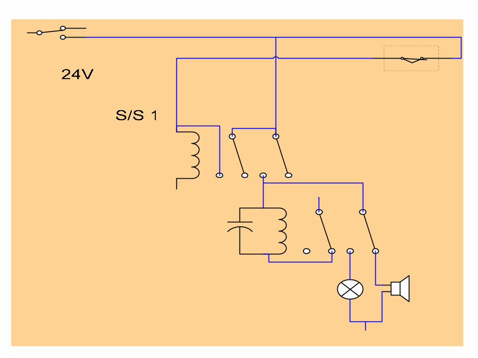
Solution of Ex. 3
How?
Design in your group and do testing on the testing board. Buzzer isn’t there, so please replace it with a green light.

TIMER RELAY
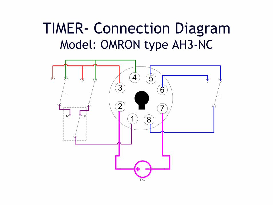
TIMER- Connection DiagramModel: OMRON type AH3-NC
DC
BA

Mode A Operation

Mode B Operation

DIODES
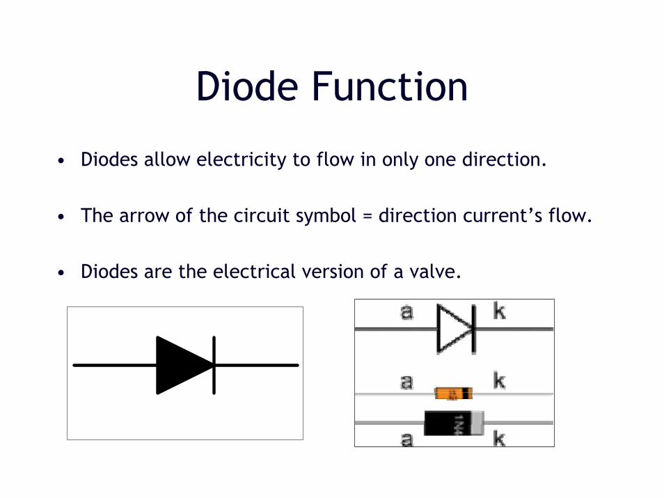
Diode Function
• Diodes allow electricity to flow in only one direction.
• The arrow of the circuit symbol = direction current’s flow.
• Diodes are the electrical version of a valve.
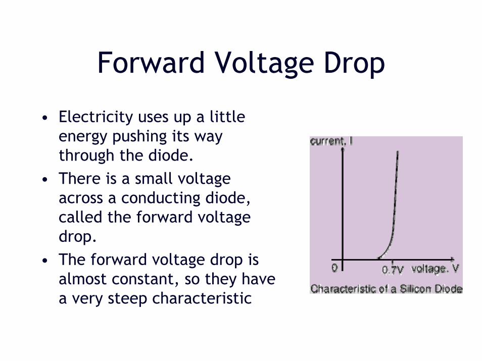
Forward Voltage Drop
• Electricity uses up a little energy pushing its way through the diode.
• There is a small voltage across a conducting diode, called the forward voltage drop.
• The forward voltage drop is almost constant, so they have a very steep characteristic

Reverse Voltage Drop
• In a reverse voltage, a perfect diode does not conduct, but all real diodes leak a very tiny current of a few µA or less.
• All diodes have a maximum reverse voltage (usually 50V or more)
• Breakdown when diode was fail and pass a large current in the reverse direction.

Testing a diode
• You can use a multimeter or a simple tester (battery, resistor and LED) to check that a diode conducts in one direction but not the other.
A lamp may be used to test a rectifier diode, but do NOT use a lamp to test a signal diode because the large current passed by the lamp will destroy the diode!
!