Embed Size (px)
Citation preview
AUXILIARY D.C. POWER SUPPLIES FOR PRIMARY & SECONDARY SUBSTATIONS
BATT-03-001 Issue No. 9
© SP Power Systems Limited Page 1 of 40
1. SCOPE
This Specification details the Company's requirements for 30V, 30/48V, 48V and 110V standby auxiliary D.C. supplies. The auxiliary D.C. supplies will be used for operation of switch tripping, protection tripping and other ancillary apparatus within primary or secondary substations.
2. ISSUE RECORD
This is a Reference document. The current version is held on the EN Document Library. It is your responsibility to ensure you work to the current version. Issue Date Issue No. Author Amendment Details June 2009 6 D Neilson 6th Issue, Update to Drawings Sept 2010 7 P Dolan 7th Issue, Major Amendments to Document. Addition
of load disconnection functionality for in line with Black Start Resilience Strategy
March 2014 8 P Dolan 8th Issue, Updates to System Types and Requirements
Dec 2016 9 P Dolan 9th Issue, Updates to Battery Fusing Arrangements, DC Inputs and addition of separate distribution board requirements
3. ISSUE AUTHORITY
Author Owner Issue Authority Patrick Dolan Lead Engineer
Alastair Ferguson Substations Manager
Martin Hill Head of Engineering Design and Standards
4. REVIEW
This is a Reference document which has a 5 year retention period after which a reminder will be issued to review and extend retention or archive.
5. DISTRIBUTION
This document is not part of a Manual maintained by Document Control and does not have a maintained distribution list.
AUXILIARY D.C. POWER SUPPLIES FOR PRIMARY & SECONDARY SUBSTATIONS
BATT-03-001 Issue No. 9
© SP Power Systems Limited Page 2 of 40
6. CONTENTS
1. SCOPE ........................................................................................................................................... 1 2. ISSUE RECORD ............................................................................................................................ 1 3. ISSUE AUTHORITY ....................................................................................................................... 1 4. REVIEW ......................................................................................................................................... 1 5. DISTRIBUTION .............................................................................................................................. 1 6. CONTENTS .................................................................................................................................... 2 7. DEFINITIONS AND STANDARDS ................................................................................................ 4
7.1 Definitions ................................................................................................................................. 4 7.2 International and British Standards .......................................................................................... 4 7.3 Equipment Components to be offered for Approval ................................................................. 4
8. REFERENCES ............................................................................................................................... 5
8.1 Statutory Legislation ................................................................................................................. 5 8.2 International Standards ............................................................................................................ 5 8.3 British Standards (BS) .............................................................................................................. 5 8.4 ENA Technical Specifications (TS) and Engineering Recommendations (ER) ....................... 5 8.5 SPEN Documents..................................................................................................................... 5 8.6 Drawings ................................................................................................................................... 5
9. REQUIREMENTS ........................................................................................................................... 6
9.1 General Requirements ............................................................................................................. 6 9.2 Equipment Standards ............................................................................................................... 7 9.3 Equipment Description ............................................................................................................. 7 9.4 Departures from Specification .................................................................................................. 7 9.5 Charger Requirements ............................................................................................................. 8
9.5.1 Input ................................................................................................................................... 8 9.5.2 Charger Output .................................................................................................................. 8 9.5.3 Environment ...................................................................................................................... 8 9.5.4 Charger Asset Life Expectancy ......................................................................................... 8 9.5.5 Terminals and Connectors ................................................................................................ 8 9.5.6 Small Wiring ...................................................................................................................... 9
9.6 Battery ...................................................................................................................................... 9 9.7 Charger Controls, Indications and Alarms ............................................................................. 10
9.7.1 Auto Test Facility ............................................................................................................. 10 9.7.2 Battery Deep Discharge Protection ................................................................................. 10 9.7.3 High Voltage Charger shutdown ..................................................................................... 10 9.7.4 Test Discharge Function ................................................................................................. 11 9.7.5 Local Indications and Remote Alarms ............................................................................. 11 9.7.6 Voltage Monitoring .......................................................................................................... 12
9.8 Enclosure and Distribution Board Requirements ................................................................... 12 9.8.1 Enclosure Requirements ................................................................................................. 12 9.8.2 Cable Entry ...................................................................................................................... 13 9.8.3 Labelling of Fittings ......................................................................................................... 13 9.8.4 A.C. Supply ...................................................................................................................... 14 9.8.5 D.C. Busbars and Distribution ......................................................................................... 14 9.8.6 Fuse and Links ................................................................................................................ 14 9.8.7 D.C. Temporary Connections Way.................................................................................. 14 9.8.8 D.C. Load Disconnection ................................................................................................. 15
9.9 Testing .................................................................................................................................... 16 9.9.1 Charger Transformer and Circuit Insulation .................................................................... 16 9.9.2 Environmental Testing Requirements ............................................................................. 16
AUXILIARY D.C. POWER SUPPLIES FOR PRIMARY & SECONDARY SUBSTATIONS
BATT-03-001 Issue No. 9
© SP Power Systems Limited Page 3 of 40
10. BATTERY SYSTEMS INDIVIDUAL REQUIREMENT SCHEDULES ......................................... 17 11. WORKS INSPECTION ................................................................................................................. 32 12. COMMISSIONING, OPERATION AND MAINTENANCE MANUAL ........................................... 32 13. APPROVAL .................................................................................................................................. 32 14. QUALITY REQUIREMENTS ........................................................................................................ 32
14.1 Quality Assurance .................................................................................................................. 32 14.2 Progress and Inspection Requirements ................................................................................. 32 14.3 Quality Plans/Inspection Checklists ....................................................................................... 32 14.4 Inspection and Witnessing of Tests ........................................................................................ 32 14.5 Retention of Quality Records ................................................................................................. 33 14.6 Certificate of Conformance ..................................................................................................... 33
15. PROTECTION AND PACKAGING .............................................................................................. 33 16. DELIVERY .................................................................................................................................... 33 17. INFORMATION REQUIRED FROM THE TENDERER ............................................................... 34 18. SCHEDULES TO BE COMPLETED BY TENDERER ................................................................. 35
18.1 TECHNICAL SCHEDULE B1: BATTERY .............................................................................. 35 18.2 TECHNICAL SCHEDULE B2: CHARGER ............................................................................. 37 18.3 TECHNICAL SCHEDULE B3: ENVIRONMENTAL TESTING COMPLIANCE STATEMENTS
................................................................................................................................................ 37 18.4 TECHNICAL SCHEDULE B4: DEPARTURES FROM SPECIFICATION .............................. 38 18.5 SCHEDULE B5: PRICES FOR BATTERY SYSTEMS TYPES ............................................. 39 18.6 SCHEDULE B6: PRICES FOR BATTERY SETS .................................................................. 40
AUXILIARY D.C. POWER SUPPLIES FOR PRIMARY & SECONDARY SUBSTATIONS
BATT-03-001 Issue No. 9
© SP Power Systems Limited Page 4 of 40
7. DEFINITIONS AND STANDARDS
7.1 Definitions
For the purpose of this specification, the following definitions shall apply: Approved: Equipment which is approved in accordance with SP Energy Networks
documents for use or installation on the Company network.
Company: Refers to SP Distribution plc, SP Transmission plc and SP Manweb plc.
Energisation: The application of Voltage to an item(s) of Equipment from the system.
Engineer: The Company’s representative having authority over technical matters contained in this Specification.
New: Approved Equipment which has not previously been connected to the system and which has been routine tested in a Manufacturing Facility with a Quality Management System in accordance with the relevant standard prior to delivery.
SPEN: SP Energy Networks, the brand name for the division of the ScottishPower group of Companies that encompasses SP Distribution plc, SP Manweb plc, SP Transmission plc, SP Power Systems Ltd and ScottishPower Energy Networks Holdings Ltd.
SP Distribution plc: The Distribution Licence Holder for the distribution service area formerly known as ScottishPower.
SP Transmission plc: The Transmission Licence Holder for the transmission service area formerly known as ScottishPower.
SP Manweb plc: The Distribution Licence Holder for the distribution service area formerly known as Manweb.
Tenderer: The supplier invited to tender in accordance with this Specification.
7.2 International and British Standards
Equipment must preferably comply with all specified requirements, including those in the British Standards or other primary standards listed in this Specification, and all ENA Technical Specifications to which this standard refers. Where equipment is designed to an associated or equivalent standard, the Tenderer shall state in the tender all variations from the listed primary standard in equipment design/performance, and shall state the title of any Associated or equivalent standard.
7.3 Equipment Components to be offered for Approval
Where components are specified in general terms, and specific types stated to be Approved items, equivalents may be offered for Approval. However, this must be made clear in the tender documents and sufficient information on the design and engineering performance of the equivalent components must be provided to enable a complete appraisal to be made. Unless otherwise specified or approved, all materials and equipment used in the contract works shall be in accordance with the latest revisions, at the time of tender of such Company Technical Specification, Electricity Networks Association Technical Specification, British Standards, ISO and IEC Standards as are applicable, and in that order of preference.
AUXILIARY D.C. POWER SUPPLIES FOR PRIMARY & SECONDARY SUBSTATIONS
BATT-03-001 Issue No. 9
© SP Power Systems Limited Page 5 of 40
8. REFERENCES
The following standards and other documents are referred to in this Specification:
8.1 Statutory Legislation
Health and Safety at Work Act 1974 Electricity at Work Regulations 1989 Provision and Use of Work Equipment Regulations 1992
8.2 International Standards
IEC 60297 Dimensions of mechanical structures of the 482.6mm (19in) series IEC 61000 Electromagnetic compatibility (EMC) IEC 60068 Environmental Testing IEC 62271-1 Marking and labelling of enclosures IEC 60269-1 Low Voltage Fuses
ETS 300 132-2 Environment Engineering (EE); Power supply interface at the input to telecommunications equipment; Part 2: Operated by direct current (dc)
8.3 British Standards (BS)
BS 88 D.C. Cartridge fuses for voltages up to and including 1 000V A.C. and 1 500V BS 923 Guide on high voltage testing techniques BS 5499 Safety Warning Labels BS 6121 Mechanical cable glands BS 6132 Safe operation of alkaline secondary cells and batteries BS 6133 Safe operation of lead-acid stationary batteries BS 6231 Specification for PVC-insulated cables for switchgear and control wiring BS 6290 - Part 4 Specification lead acid valve regulated sealed type batteries BS 7671 IEE Wiring Regulations Seventeenth Edition BS EN 61558 Safety of power transformers, power supplies reactors and similar products BS EN 60898 Circuit–breakers for over current protection BS EN 608696-21 Stationary lead-acid batteries: Value regulated types – Methods of test BS EN 608696-22 Stationary lead-acid batteries: Value regulated types – Requirements
8.4 ENA Technical Specifications (TS) and Engineering Recommendations (ER)
ENA TS 09-6 Auxiliary multi-core and multi pair cables ENA TS 50-18 Design and application of ancillary electrical equipment ENA TS 98-1 Surface preparation and paint finish of new plant and equipment ENA TS 50-19 Standard numbering for small wiring ENA TS 48-5 Environmental Testing for Protection Applications ER G5/ 4 Limits for harmonics in the UK electricity supply system
8.5 SPEN Documents
BATT-03-003 Substations D.C. Load Management Controller Requirements BATT-06-001 Approved Equipment Register BATTERIES
8.6 Drawings
The schematic drawings for requested Battery Systems are shown in Section 10, BATTERY SYSTEMS INDIVIDUAL REQUIREMENT SCHEDULES.
AUXILIARY D.C. POWER SUPPLIES FOR PRIMARY & SECONDARY SUBSTATIONS
BATT-03-001 Issue No. 9
© SP Power Systems Limited Page 6 of 40
9. REQUIREMENTS
9.1 General Requirements
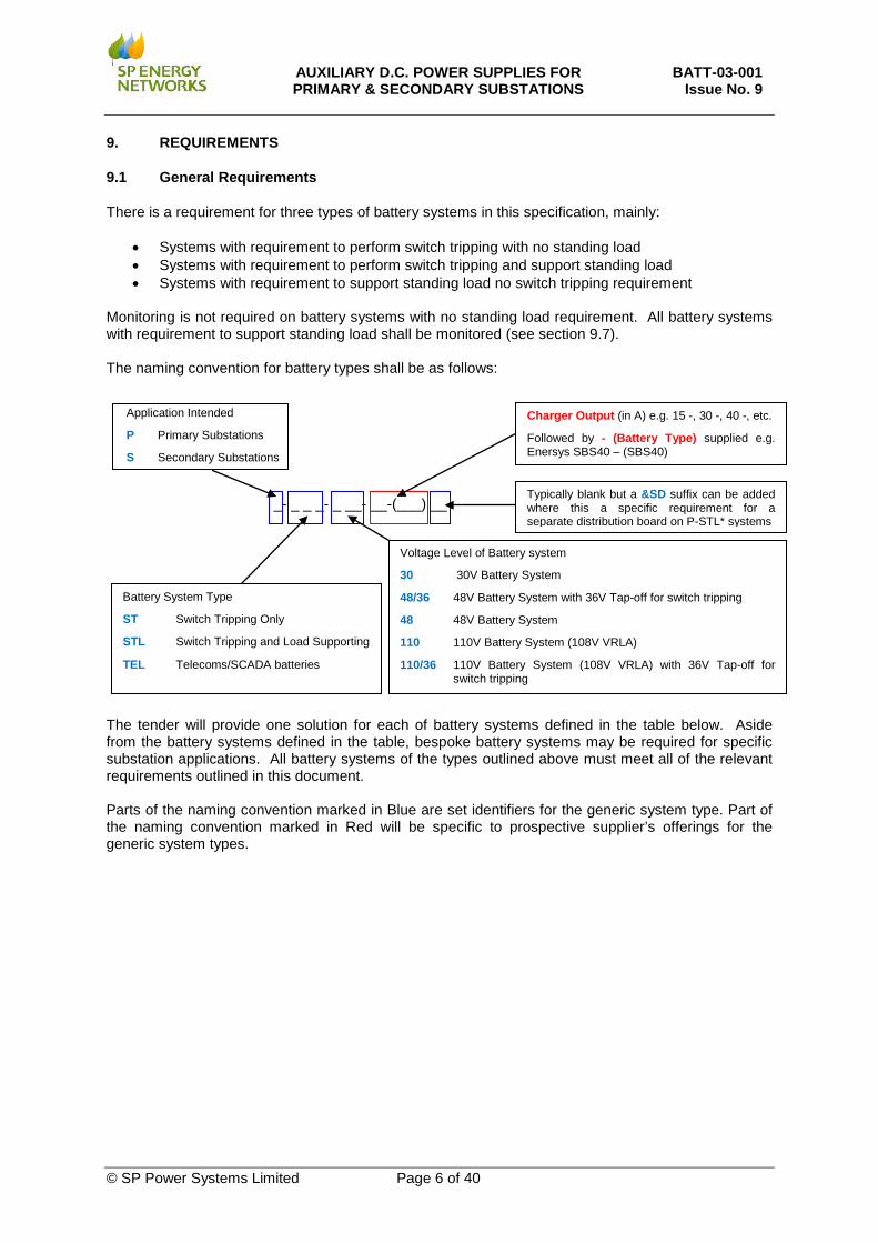
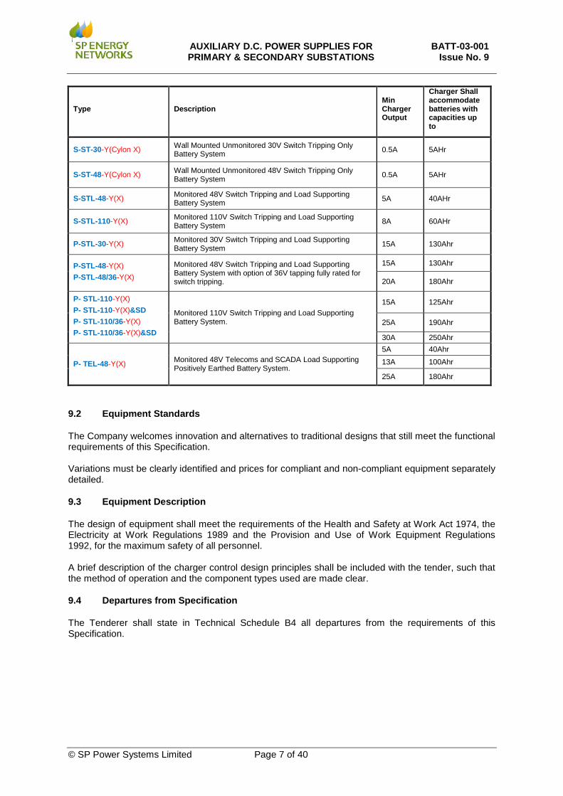
There is a requirement for three types of battery systems in this specification, mainly:
• Systems with requirement to perform switch tripping with no standing load • Systems with requirement to perform switch tripping and support standing load • Systems with requirement to support standing load no switch tripping requirement
Monitoring is not required on battery systems with no standing load requirement. All battery systems with requirement to support standing load shall be monitored (see section 9.7). The naming convention for battery types shall be as follows: _- _ _ _- _ __- __-(___) __ The tender will provide one solution for each of battery systems defined in the table below. Aside from the battery systems defined in the table, bespoke battery systems may be required for specific substation applications. All battery systems of the types outlined above must meet all of the relevant requirements outlined in this document. Parts of the naming convention marked in Blue are set identifiers for the generic system type. Part of the naming convention marked in Red will be specific to prospective supplier’s offerings for the generic system types.
Battery System Type
ST Switch Tripping Only
STL Switch Tripping and Load Supporting
TEL Telecoms/SCADA batteries
Voltage Level of Battery system
30 30V Battery System
48/36 48V Battery System with 36V Tap-off for switch tripping
48 48V Battery System
110 110V Battery System (108V VRLA)
110/36 110V Battery System (108V VRLA) with 36V Tap-off for switch tripping
Application Intended
P Primary Substations
S Secondary Substations
Charger Output (in A) e.g. 15 -, 30 -, 40 -, etc.
Followed by - (Battery Type) supplied e.g. Enersys SBS40 – (SBS40)
Typically blank but a &SD suffix can be added where this a specific requirement for a separate distribution board on P-STL* systems
AUXILIARY D.C. POWER SUPPLIES FOR PRIMARY & SECONDARY SUBSTATIONS
BATT-03-001 Issue No. 9
© SP Power Systems Limited Page 7 of 40
Type Description Min Charger Output
Charger Shall accommodate batteries with capacities up to
S-ST-30-Y(Cylon X) Wall Mounted Unmonitored 30V Switch Tripping Only Battery System 0.5A 5AHr
S-ST-48-Y(Cylon X) Wall Mounted Unmonitored 48V Switch Tripping Only Battery System 0.5A 5AHr
S-STL-48-Y(X) Monitored 48V Switch Tripping and Load Supporting Battery System 5A 40AHr
S-STL-110-Y(X) Monitored 110V Switch Tripping and Load Supporting Battery System 8A 60AHr
P-STL-30-Y(X) Monitored 30V Switch Tripping and Load Supporting Battery System 15A 130Ahr
P-STL-48-Y(X) P-STL-48/36-Y(X)
Monitored 48V Switch Tripping and Load Supporting Battery System with option of 36V tapping fully rated for switch tripping.
15A 130Ahr
20A 180Ahr
P- STL-110-Y(X) P- STL-110-Y(X)&SD P- STL-110/36-Y(X) P- STL-110/36-Y(X)&SD
Monitored 110V Switch Tripping and Load Supporting Battery System.
15A 125Ahr
25A 190Ahr
30A 250Ahr
P- TEL-48-Y(X) Monitored 48V Telecoms and SCADA Load Supporting Positively Earthed Battery System.
5A 40Ahr
13A 100Ahr
25A 180Ahr
9.2 Equipment Standards
The Company welcomes innovation and alternatives to traditional designs that still meet the functional requirements of this Specification. Variations must be clearly identified and prices for compliant and non-compliant equipment separately detailed.
9.3 Equipment Description
The design of equipment shall meet the requirements of the Health and Safety at Work Act 1974, the Electricity at Work Regulations 1989 and the Provision and Use of Work Equipment Regulations 1992, for the maximum safety of all personnel. A brief description of the charger control design principles shall be included with the tender, such that the method of operation and the component types used are made clear.
9.4 Departures from Specification
The Tenderer shall state in Technical Schedule B4 all departures from the requirements of this Specification.
AUXILIARY D.C. POWER SUPPLIES FOR PRIMARY & SECONDARY SUBSTATIONS
BATT-03-001 Issue No. 9
© SP Power Systems Limited Page 8 of 40
9.5 Charger Requirements
Inputs and Outputs to the charger shall be easily accessible for testing purposes. The Tenderer will be required to complete the Technical Schedule B2.
9.5.1 Input
The charger will be operated from a 230V A.C. 50 Hz single-phase supply. The variations of supply will be between +10/-10% of the voltage and +/-1% of the frequency. Isolation between input and output shall be provided by a double wound transformer having its windings separated by an earth screen in accordance with BS EN 61558, and further detailed in BS 7671: IEE Wiring Regulations: Protective measure: extra low voltage 414.3 & 414.4.
9.5.2 Charger Output
All battery chargers shall include temperature compensated charging capability. The voltage output setting range of the charger shall be quoted in the tender so that all compatible batteries can be identified by the Company. Charger output settings shall be adjusted in line with the battery manufacturer’s guidelines for all batteries supplied with the associated chargers. Where batteries are not supplied with the charger a default setting of 2.30V charge per cell at 20°C shall be applied and temperature compensated charging shall be enabled. Output from the charger shall be constant D.C. with a ripple content that shall not exceed +/-3%, without the battery connected. The value of any internal discharge on loss of A.C. supply via the charger with no load connected shall be stated in the tender. Internal discharge shall not exceed 0.25mA for all battery systems not designed to support standing load (ST Systems). Internal discharge shall not exceed 25mA for (STL) load supporting battery systems and telecoms (TEL) battery systems.
9.5.3 Environment
The charger shall not produce interference on the A.C. input more than that specified in EA Engineering Recommendation G5/4. The equipment offered shall be tolerant of temperatures (-10C – +55C) and humidity levels 5% – 93%). Reference should be made to the IEC 60068-2. Systems will be installed in some environments where dust is present; therefore systems which are not reliant on forced air-cooling will be considered favourably in the enquiry.
9.5.4 Charger Asset Life Expectancy
Chargers offered for Tripping applications shall have evidence to support a minimum expectancy life of 25 years and Chargers offered for “TEL” supporting applications shall have evidence to support a minimum expectancy life of 20 years within the environments quoted. Switch Mode Rectifiers shall not be are offered for ST or STL systems. For TEL systems, Switch Mode Rectifiers shall be only considered if applied as part of a dual rectifier system.
9.5.5 Terminals and Connectors
All terminations shall be to EATS 50-18. The main connections between the charger unit, battery and D.C. distribution board shall be provided by PVC or XLPE insulated cable of adequate mechanical strength and current carrying capacity, and terminating in two ring type terminations on the battery.
AUXILIARY D.C. POWER SUPPLIES FOR PRIMARY & SECONDARY SUBSTATIONS
BATT-03-001 Issue No. 9
© SP Power Systems Limited Page 9 of 40
Terminals & connectors shall be protected against inadvertent contact by an operator. Battery terminal shrouding shall allow access for maintenance and measurement. The P-STL-48/36 and P-STL-48/36 battery systems shall have a reduced tapping point at 36V that shall be fully rated.
9.5.6 Small Wiring
Small wiring shall be suitably rated stranded conductor, Type B, in accordance with BS 6231. Wires shall be coloured in accordance with the following code: ENATS 50-18 ‘small wiring shall be coloured white, except for earth cables, which shall be Green/Yellow. End marking shall be in accordance with clause 4.8. All wires at the equipment interface point shall have numbered ferrules at both ends in accordance with ENATS 50-19.
9.6 Battery
Chargers will normally be required with batteries. The type of battery offered with the chargers will be at the choice of the Tenderer. SP will consider favourably solutions which represent the lowest lifetime asset cost. Currently the lowest cost solution is perceived to be based on VRLA batteries technology however; SP will consider battery systems that the manufacturer considers to better the performance and lifetime cost of a VRLA battery system. The required life expectancy of the battery shall be 10 years or greater at environmental conditions (-10°C – +25°C). A statement to that effect shall be included in the tender. Where nominal 110V VRLA Battery sets are requested, 108V made up of 54 Cells (9X12V Blocks) are required. The Battery System (Charger, Fittings, Wiring, D.C. distribution board) shall be capable of withstanding the D.C. short circuit current of any batteries (sets) offered as per BS EN 608696-22:2004, Clause 6.3. VRLA batteries submitted in the Tenderer’s proposal shall be tested in accordance with BS EN 608696-21:2004 and meet all requirements identified in BS EN 60896-22:2004. Test data for all tests performed on the VRLA batteries proposed shall be made available upon request. The tender will need to complete Schedule B1 for any batteries offered for consideration for all products not currently approved as per BATT-06-001 (for the application identified), this requests information relating to a number of the tests specified in BS EN 60896-22. Further information required from the Tenderer regarding battery selection shall be completed in Technical Schedule B1 - Battery. All batteries shall be clearly marked to identify the manufacturer, the type reference and the date of manufacture, which shall not be a code. This marking shall be clearly visible from the front of the unit without dismantling the batteries. The +ve and -ve, and all reduced voltage terminals shall be clearly labelled. All batteries shall be supplied in a fully charged condition and within 3 months from date of manufacture. Approval in writing shall be obtained from the Engineer for batteries offered in this contract; any deviations for new solutions should be referenced against BATT-06-001 - Approved Equipment Register, Batteries.
AUXILIARY D.C. POWER SUPPLIES FOR PRIMARY & SECONDARY SUBSTATIONS
BATT-03-001 Issue No. 9
© SP Power Systems Limited Page 10 of 40
9.7 Charger Controls, Indications and Alarms
The charger fittings required will be specific to the individual battery systems required and are detailed in the individual system schedules outlined in section 10. Voltmeters and Ammeters may be by means of analogue instruments or via LCD displays. The Voltage Across each battery set shall be monitored and displayed locally and transmitted remotely. All Battery Systems shall have Test switches of the self re-set type controlling a battery test load. Where specified D.C. charger input fuse holders shall be fitted with appropriately rated HRC fuses, to allow the D.C. supply to be maintained from an alternative source while maintenance/ replacement of the main battery cells is undertaken. Where specified, battery monitoring shall have the following features:
• Periodic battery asymmetry monitoring and alarm; • Periodic battery impedance monitoring and alarm (preferred, not essential); • Configurable High and Low voltage detection and alarm:
o These must be set to manufacturer’s recommendation for specific cells used where cells are supplied with the charger
o Where chargers are supplied without cells the following default settings must be applied:
Low Alarm – 2.1V / cell (Default) Low Alarm Reset – 2.25V / cell, 30 sec alarms reset required High Alarm – 2.4V / cell (Default), 2.5 Seconds reset required High Voltage Charger shutdown and alarm– 2.53V/Cell (Default)
• High Volts shutdown shall be manual reset (and reconnection via a push button switch).
• An earth fault alarm shall be configured for STL battery systems; this is not required for positive earthed TEL battery systems:
o This shall detect Earth faults on either pole of the associated D.C. system • Supply fail and charger failure alarm; • Fuse Fail Alarms (TEL Systems Only).
9.7.1 Auto Test Facility
The facility to automatically test the battery sets by switching charger output down and supply the standing load (only) shall be provided with all STL and TEL D.C. systems. The regularity and duration of the test should be adjustable and be executed in a manner where there is no risk to the continuity of supply to the load and such that there is no appreciable degradation of the battery asset life.
9.7.2 Battery Deep Discharge Protection
Consideration will be given to all solutions available to prevent deep discharge on TEL battery systems and STL systems intended for use in secondary substations. Details of all solutions offered and option costs where applicable should be included in the enquiry. Where offered, associated systems shall have the facility to enable or disable deep discharge protection as required.
9.7.3 High Voltage Charger shutdown
The high voltage and charger shutdown facility should, alarm and cut-off respectively when the charger output goes beyond a pre-set threshold (default 2.53V/Cell). Reconnection of the charger supplies should be manually initiated by a dedicated push button.
AUXILIARY D.C. POWER SUPPLIES FOR PRIMARY & SECONDARY SUBSTATIONS
BATT-03-001 Issue No. 9
© SP Power Systems Limited Page 11 of 40
9.7.4 Test Discharge Function
All systems shall include a dedicated Push Button; Self Reset Type which when pressed imposes a battery test load in addition to all connected D.C. loads. Safeguards must be provided to ensure that the load is not applied for a period exceeding 10 seconds. When connected, the test load shall draw a current equal or greater than the charger output capability / C10 Current Rate of associated battery. This switch shall either disconnect the charger or lower the charger output when pressed and shall either initiate an alarm if battery problem is detected or give a visual indication of battery output voltage for the duration of the test (for unmonitored systems). The test load resistor shall be located within the battery and charger system and shall be placed in manner as to reduce risk of fire and risk of personal contact.
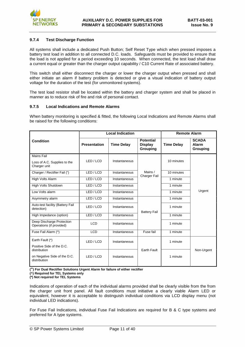
9.7.5 Local Indications and Remote Alarms
When battery monitoring is specified & fitted, the following Local Indications and Remote Alarms shall be raised for the following conditions:
Condition
Local Indication Remote Alarm
Presentation Time Delay Potential Display Grouping
Time Delay SCADA Alarm Grouping
Mains Fail
Loss of A.C. Supplies to the Charger unit
LED / LCD Instantaneous
Mains / Charger Fail
10 minutes
Urgent
Charger / Rectifier Fail (“) LED / LCD Instantaneous 10 minutes
High Volts Alarm LED / LCD Instantaneous 1 minute
High Volts Shutdown LED / LCD Instantaneous 1 minute
Low Volts alarm LED / LCD Instantaneous 1 minute
Asymmetry alarm LED / LCD Instantaneous
Battery Fail
1 minute
Auto-test facility (Battery Fail detection) LED / LCD Instantaneous 1 minute
High Impedance (option) LED / LCD Instantaneous 1 minute
Deep Discharge Protection Operations (if provided) LCD Instantaneous 1 minute
Fuse Fail Alarm (^) LCD Instantaneous Fuse fail 1 minute
Earth Fault (*)
Positive Side of the D.C. distribution
on Negative Side of the D.C. distribution
LED / LCD Instantaneous
Earth Fault
1 minute
Non-Urgent
LED / LCD Instantaneous 1 minute
(“) For Dual Rectifier Solutions Urgent Alarm for failure of either rectifier (^) Required for TEL Systems only (*) Not required for TEL Systems Indications of operation of each of the individual alarms provided shall be clearly visible from the from the charger unit front panel. All fault conditions must initiative a clearly viable Alarm LED or equivalent, however it is acceptable to distinguish individual conditions via LCD display menu (not individual LED indications). For Fuse Fail Indications, individual Fuse Fail Indications are required for B & C type systems and preferred for A type systems.
AUXILIARY D.C. POWER SUPPLIES FOR PRIMARY & SECONDARY SUBSTATIONS
BATT-03-001 Issue No. 9
© SP Power Systems Limited Page 12 of 40
Remote alarms shall only be raised after a specified time delay and shall be cancelled in the condition which has initiated the condition is not sustained to stop nuisance alarms caused by transients. When battery monitoring is specified & fitted, alarm contacts should be of the normally closed in the de-energised state and shall be held open under normal conditions. Any failure in the relays from which the alarms are derived shall result in the issue of the associated alarm(s). All alarms should be non-latching (or "self-resetting") in nature and shall be presented as volt-free contacts (wetting current 5-20mA). In addition to generic requirements alarm output requirements, TEL (B & C)Type Systems shall be remote managed by IP using HPOV or similar, this functionality is preferred for TEL (A) Type Systems but not essential. The supplier shall ensure that all MIBS used are pre-determined and agreed with the Company. A RJ45 connection shall be made available for the remote management.
9.7.6 Voltage Monitoring
The Voltage Across each battery set shall be monitored and transmitted remotely for selected Primary Substation STL Systems confirmed in schedules, Section 10 BATTERY SYSTEMS INDIVIDUAL REQUIREMENT SCHEDULES. The minimum of accuracy of all measured analogue values shall be +/- 1%. Outputs should be presented in either of the following formats as required:
• 0 – 10mA • 4 – 20mA
If offered, options for serial communications will be considered on an individual application basis.
9.8 Enclosure and Distribution Board Requirements
9.8.1 Enclosure Requirements
All Cabinets shall have a minimum rating of IP31, BS EN 60529. All cabinets provided shall be of sheet steel construction throughout. Where a cubicle has been specified to house a full D.C. system associated sub-elements of the system should be grouped together within the same panel. Charger components, distribution ways and batteries should be segregated and clearly labelled on both the front and rear of the cubicle. Provision should be made to accommodate a future load disconnection device within the charger cabinet (a minimum rack space of 4u height) for all systems where this requirement is identified, Section 10. Considerations shall be given to the future maintenance and repair of all battery system components contained within cubicles at the time of the design. All Cabinets which house batteries shall have adequate ventilation at the highest point to prevent the potential build-up of gases should overcharging occur. Cabinet ventilation shall be designed to safely handle gas emissions as would be expected for batteries declared as compatible with the system as per clause 6.1, BS EN 608696-21:2004 (or otherwise applicable standards where an alternative technology to Lead Acid Batteries is offered). Arrangement of the cabinets for housing batteries should take into consideration the codes of practice set out in BS 6133 for lead acid or BS 6132 for alkaline depending on the chosen battery. Each cabinet shall be acid and alkali resistant.
AUXILIARY D.C. POWER SUPPLIES FOR PRIMARY & SECONDARY SUBSTATIONS
BATT-03-001 Issue No. 9
© SP Power Systems Limited Page 13 of 40
All cabinets housing batteries shall be arranged such that all cells/battery blocks can be visually inspected in situ. Where applicable, the cabinets shall be adequately sized to allow topping up of cells in situ and arranged so that cell levels can be viewed with all cells in position. Battery inspection, maintenance and cell replacement should be able to be carried out by accessing the batteries through doors of the cabinet which do not require tools for access. The charger components and alarm relay should be sufficiently accessible for test purposes, and for replacement, without compromising the safety of the personnel. All cabinets shall be fitted with removable M12 high tensile brass earth studs at the bottom of both sides of the cabinet for connecting the substation earth bar to the cabinet for earthing all metalwork. Lifting eyes shall be provided on all free-standing cabinets. Wall mounted Cabinets which weight more than 50kg shall also be provided with lifting eyes. Cabinets shall be adequately packed to avoid damage in transit. Where reasonably practical a robust pocket, suitable for accommodating the “Commissioning, Operation and Maintenance Manual” and the Battery Logbook, shall be provided on the inside of the cubicle. In addition to the generic cabinet requirements, individual battery systems have the specific requirements detailed in the individual battery system requirements schedules section 10. A drawing of the cabinet(s) layout shall be provided at the time of tender. The available space for the accommodation of the battery shall be clearly stated in the tender. The Engineer shall agree cabinet(s) design and layout before the award of the contract.
9.8.2 Cable Entry
Cable entry requirements will be specific to individual systems / distribution boards and as such are defined in battery systems requirements schedules, section 10. Where Cable Glands are provided they shall be to BS 6121. There should be adequate access internal to the cabinet enable wiring to internal terminals from each respective cable entry point. There shall be no requirement to modify or dismantle any internal panels to terminate cables of continuous current carrying capacity equal to or greater that the fuses designated for associated D.C. ways. Sufficient space shall be available in the enclosure such that associated cables are able to be terminated without exceeded the manufacturers recommended bend radii and without impinging on any surface or apparatus within the enclosure.
9.8.3 Labelling of Fittings
All enclosures shall be marked in accordance with Clause 5-10 of IEC 62271-1 as referred to in ENA TS 50-18. A label showing black letters on a white background shall be affixed adjacent to each fitting and terminal, to indicate the function. In the case of a relay, if there is a visible internal label, no additional label is required. Each Cabinet shall be identified by a non-corroding indelibly marked data plate giving the following information, and marked in accordance with ENA TS 50-18.
• Manufacturer’s Name • Year of Manufacture • Serial Number • Diagram of Connections, Drawing Number • The Company’s Order Number
Safety-warning labels shall comply with BS 5499 referenced in ENA TS 50-18.
AUXILIARY D.C. POWER SUPPLIES FOR PRIMARY & SECONDARY SUBSTATIONS
BATT-03-001 Issue No. 9
© SP Power Systems Limited Page 14 of 40
9.8.4 A.C. Supply
Each charger’s input supply shall be fitted with appropriately rated 2 pole MCB which comply with ENA TS 50-18 and BS EN 60898 -1 and accommodate the maximum inrush of the transformer associated with the charger system.
9.8.5 D.C. Busbars and Distribution
The Fusing/Linking and D.C. distribution arrangements of the battery and battery system controller / Instrumentation and distribution ways shall be at the adequate for the systems where they are provided including safely requirements listed in BS EN 50272-1 and BS EN 50272-2. It shall be possible to fully isolate charger unit from D.C. Busbars and Battery. Each ring and spare way shall be supplied with suitable labelling of output fuse holders. Suggested distribution configurations are listed in charger schedules, Section 10 which includes options for batteries and chargers with integrated distribution boards and external distribution boards. Variations from these nominal distribution arrangements will be requested as required for individual site requirements. Battery Systems with an integrated D.C. Distribution board where the charger can be replaced without disturbing the D.C. Distribution board shall be looked upon favourably in the tender. In Systems with a separate D.C. distribution board, it shall be possible to locally isolate the distribution board from the battery and charger unit with the aid of a lockable isolation switch. Termination for outgoing distribution cables shall be provided on a terminal block that will then be wired to a fuse way fitted with locknuts and washers.
9.8.6 Fuse and Links
Battery connections and all distribution ways shall be fitted with Fuse Holders and protected with appropriately rated HRC fuses. Fuses and Links, shall be cartridge type, BS88 and comply with EATS 50-18 Clause 6, IEC 60269-1. Fuse bases and associated carriers intended to accommodate a fuse link shall be of clearly distinguishable colour. Fuse bases and associated fuse carriers intended to accommodate a solid –link (non-fusible link) shall be coloured white. Each battery string shall be fused on both the positive and negative poles for all applications. Systems offered shall be adequately protected as to withstand the maximum battery short circuit current appropriate to the battery (set) offered BS EN 60896-22: Clause 6.3. All STL Chargers shall be provided with a spare set of Battery Fuses secured to the internal side of the charger front panel door.
9.8.7 D.C. Temporary Connections Way
Anderson SB175 or equivalent Sockets for connection of temporary supplies or test loads shall be provided for Battery Systems Distributions where this requirement is identified as per section 10. These D.C. Sockets shall be 2 Connector Multi-pole Type, D.C. socket of a size and rating appropriate to the associated D.C. System mounded such that associated plugs cannot be fitted incorrectly. Full details of the proposed make and type should be included in tender for approval. Sockets shall be provided on the distribution board busbars and shall have labels affixed stating “Connections shall only be made to the input socket where there is adequate source protection on the incoming supply and the supply is equal in voltage to the battery and charger system to which it is being connected”.
AUXILIARY D.C. POWER SUPPLIES FOR PRIMARY & SECONDARY SUBSTATIONS
BATT-03-001 Issue No. 9
© SP Power Systems Limited Page 15 of 40
Sockets shall be provided feeder side of the outgoing tripping supplied derived from a tap off from a higher voltage battery where this arrangement is provided. Associated sockets shall have labels affixed stating “Connections shall only be made to the input socket where there is adequate source protection on the incoming supply and after the outgoing way has been isolated from the battery and charger system”. Additionally sockets may be supplied downstream of battery fuseways for battery testing purposes at the option of the tenderer.
9.8.8 D.C. Load Disconnection
All primary substations STL battery systems which support a standing D.C. load shall be constructed such that controllers for disconnecting selected D.C. loads can be easily integrated into the battery and charger system as required. The requirements of Load disconnection control systems that may be added are specified in BATT-03-003. The minimum requirement within associated battery charger systems shall be the provision of a removable bolted link on the Positive D.C. Busbar with terminals provided such that suitably rated wiring can be installed in parallel with a device capable of making/break load the when the linking bar is removed. Systems shall be provided such that fuse ways (D.C. loads) can be selectively disconnected on applications where the distributions board is integrated with battery charger system and provided as a separate board. On separate D.C distributions boards, linking and isolation shall be arranged such that it is possible to completely back feed the D.C distribution board from a single connection and fully isolation it from the battery and charger Further detail can be found in equipment schedules, section 10.
AUXILIARY D.C. POWER SUPPLIES FOR PRIMARY & SECONDARY SUBSTATIONS
BATT-03-001 Issue No. 9
© SP Power Systems Limited Page 16 of 40
9.9 Testing
9.9.1 Charger Transformer and Circuit Insulation
The insulation between windings, screen, core and frame of the transformer and circuits directly connected to the 230V A.C. shall withstand 2 kV A.C. rms, 50 Hz for one minute. Immediately afterwards the insulation resistance measured at 500 volts D.C. shall not be less than 20 MΩ. All circuits intended to be connected to the 230 V A.C. supply shall withstand 2 kV A.C. rms., 50 Hz for one minute. Immediately afterwards the insulation resistance measured at 500 V D.C. shall not be less than 20 MΩ.
9.9.2 Environmental Testing Requirements
Reference should be made to IEC 61000-4 EMC compatibility testing. The vendor shall also demonstrate that Charger Control and Alarm Modules offered as part of the overall solution meet adequate Electrical Environment and EMC Requirements by completing Tables in Schedule B3. The list of the tests to be completed are taken from ENA TS 48-5 however it is acceptable that Vendor equipment offered is tested to equivalent test procedures. The procedure used for each test must be confirmed, along with specified and actual test levels, compliance statements and acceptance criteria where appropriate. Specifically, electronic circuitry shall be type tested by application of 5 kV full standard lightning impulse with 1.2/50 µS characteristics as defined in BS 923 (or equivalent). Three positive and three negative impulses shall be applied as follows:
• Between the output terminals with the battery connected; • Between the output terminals connected together and earth, with the input terminals earthed;
and • Between the input terminals connected together and earth, with the output terminals earthed.
After the above tests, there shall be no indication of failure and the charger shall still provide the required performance. The insulation resistance between the electronic circuitry and earth when measured at 500 V D.C. shall not be less than 20 MΩ. The psophometric noise level of the complete TEL systems shall not exceed the equivalent emf of 2 mV rms at a frequency of 800 Hz after weighting as specified by ITU-T, and shall not exceed an emf of 10 mV in the frequency range 25 Hz to 5 kHz as specified in ETS 300 132-2.
AUXILIARY D.C. POWER SUPPLIES FOR PRIMARY & SECONDARY SUBSTATIONS
BATT-03-001 Issue No. 9
© SP Power Systems Limited Page 17 of 40
10. BATTERY SYSTEMS INDIVIDUAL REQUIREMENT SCHEDULES
Battery System Type(s) S-ST-30 S-ST-48 Voltage 30V 48V
Description Unmonitored 30V Switch Tripping Only Battery System
Unmonitored 48V Switch Tripping Only Battery System
Charger Output ~0.5A ~0.5A Capacity Requirements 5Ahr Capacity 5Ahr Capacity
Charger Setting Range
Charge setting range shall be adjustable such to enable all currently available batteries of the required capacity to be installed with the charger at batteries manufacturers advised settings ranges. Where temperature compensated chargers are offered ambient temperatures range shall be -10oC – 25oC.
Internal Discharge Requirements
The value of Internal Discharge on loss of A.C. supply via the charger with no load connected shall not exceed 0.25mA
Cabinet Requirements
Type Wall Mounted Maximum Dimensions Guidance 400W/300D/500H
Cable Entry Requirements 2 x 20mm with Gland plate (2 each top left and right sides) pre-drilled and covered
Charger Fittings Item Description
Meters (Section 9.7)
Voltmeter Shall give indications of voltage across charger/battery output terminals (On Push Button Acceptable)
Ammeter Shall Indicate Charge and Discharge Currents Manual Switches (Section 9.7.4)
Test Switch Dedicated Push Button Self Reset Type Controlling a battery test load which disconnects or lower charger output when pressed
Alarm Requirements No Alarms Required A.C. Input Shall be fitted with appropriately rated 2 pole MCB
D.C. Ways Requirements Fused only at Battery with 20A fuseways for single outgoing way
AUXILIARY D.C. POWER SUPPLIES FOR PRIMARY & SECONDARY SUBSTATIONS
BATT-03-001 Issue No. 9
© SP Power Systems Limited Page 18 of 40
Charger & Test Switch
+-
A
+ve
-ve
TrippingBatteries
+-
*
* May be Analogue Instrument or via Digital Display
30V for S-ST-3048V for S-ST-48
*V
230V AC50Hz
Double Pole M.C.B
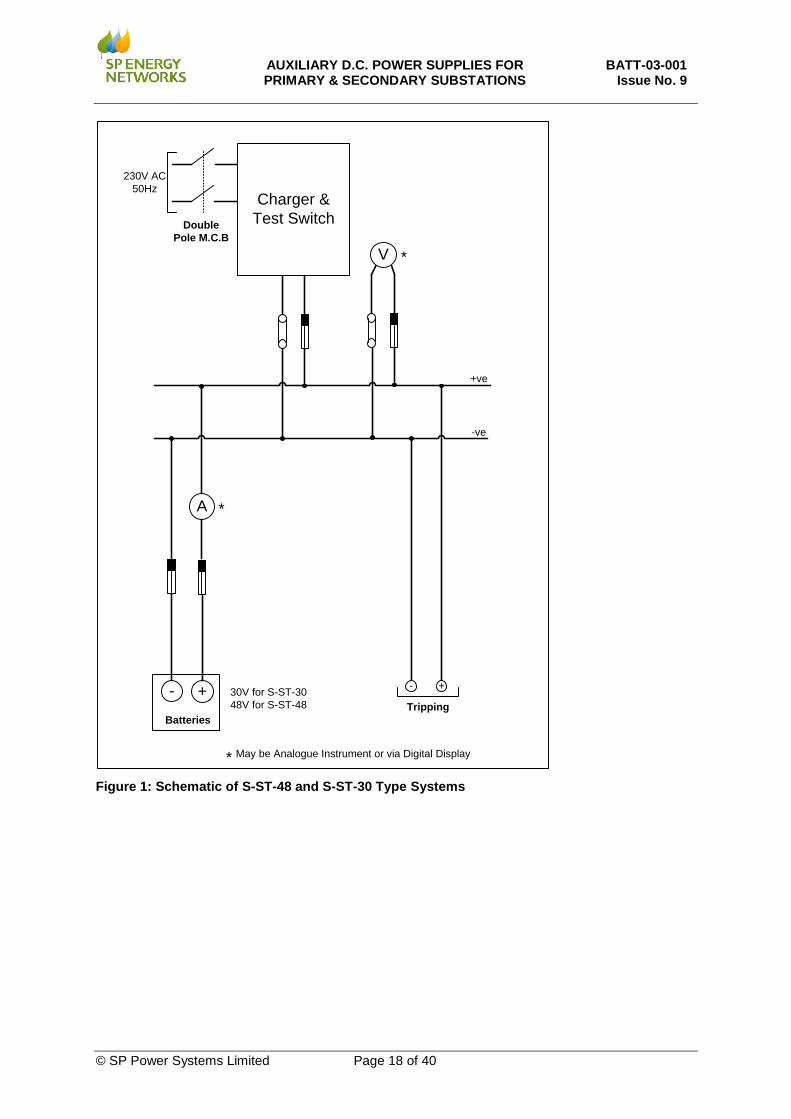
Figure 1: Schematic of S-ST-48 and S-ST-30 Type Systems
AUXILIARY D.C. POWER SUPPLIES FOR PRIMARY & SECONDARY SUBSTATIONS
BATT-03-001 Issue No. 9
© SP Power Systems Limited Page 19 of 40
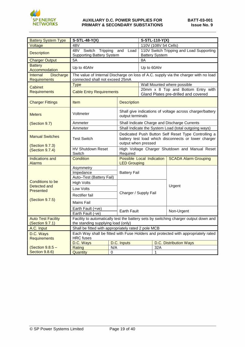
Battery System Type S-STL-48-Y(X) S-STL-110-Y(X) Voltage 48V 110V (108V 54 Cells)
Description 48V Switch Tripping and Load Supporting Battery System
110V Switch Tripping and Load Supporting Battery System
Charger Output 5A 8A Battery Accommodation Up to 40Ahr Up to 60Ahr
Internal Discharge Requirements
The value of Internal Discharge on loss of A.C. supply via the charger with no load connected shall not exceed 25mA
Cabinet Requirements
Type Wall Mounted where possible
Cable Entry Requirements 20mm x 8 Top and Bottom Entry with Gland Plates pre-drilled and covered
Charger Fittings Item Description
Meters (Section 9.7)
Voltmeter Shall give indications of voltage across charger/battery output terminals
Ammeter Shall Indicate Charge and Discharge Currents Ammeter Shall Indicate the System Load (total outgoing ways)
Manual Switches (Section 9.7.3) (Section 9.7.4)
Test Switch Dedicated Push Button Self Reset Type Controlling a battery test load which disconnects or lower charger output when pressed
HV Shutdown Reset Switch
High Voltage Charger Shutdown and Manual Reset Required
Indications and Alarms
Condition Possible Local Indication LED Grouping
SCADA Alarm Grouping
Conditions to be Detected and Presented (Section 9.7.5)
Asymmetry Battery Fail
Urgent
Impedance Auto–Test (Battery Fail) High Volts
Charger / Supply Fail Low Volts Rectifier fail
Mains Fail Earth Fault (+ve) Earth Fault Non-Urgent Earth Fault (-ve)
Auto Test Facility (Section 9.7.1)
Facility to automatically test the battery sets by switching charger output down and the standing supplying load (only)
A.C. Input Shall be fitted with appropriately rated 2 pole MCB D.C. Ways Requirements (Section 9.8.5 – Section 9.8.6)
Each Way shall be fitted with Fuse Holders and protected with appropriately rated HRC fuses D.C. Ways D.C. Inputs D.C. Distribution Ways Rating N/A 32A Quantity 0 1
AUXILIARY D.C. POWER SUPPLIES FOR PRIMARY & SECONDARY SUBSTATIONS
BATT-03-001 Issue No. 9
© SP Power Systems Limited Page 20 of 40
Charger, Control and Alarm Unit,
and Test Switch
+- 48V for S-STL-48 108V or S-STL-110
A
+ve
-ve
Tripping and Standing LoadBatteries
+-
32A
*
* May be Analogue Instrument or via Digital Display
V *
Alarm Indications may presented by LEDs or via LCD display^
A*
Urgent AlarmCommonNon-urgent Alarm230V AC
50Hz
Double Pole M.C.B
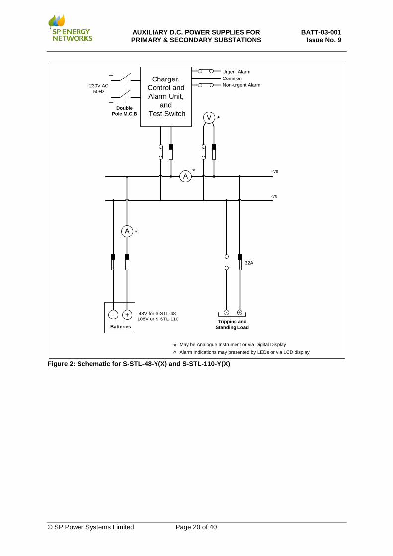
Figure 2: Schematic for S-STL-48-Y(X) and S-STL-110-Y(X)
AUXILIARY D.C. POWER SUPPLIES FOR PRIMARY & SECONDARY SUBSTATIONS
BATT-03-001 Issue No. 9
© SP Power Systems Limited Page 21 of 40
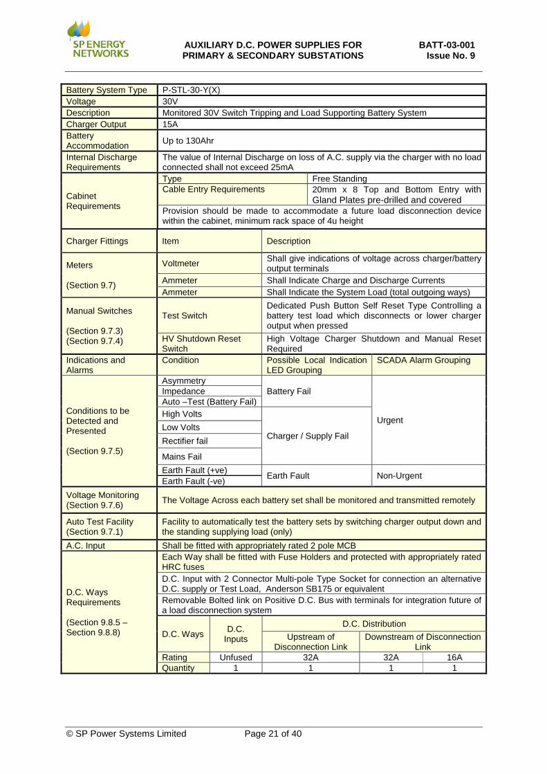
Battery System Type P-STL-30-Y(X) Voltage 30V Description Monitored 30V Switch Tripping and Load Supporting Battery System Charger Output 15A Battery Accommodation Up to 130Ahr
Internal Discharge Requirements
The value of Internal Discharge on loss of A.C. supply via the charger with no load connected shall not exceed 25mA
Cabinet Requirements
Type Free Standing Cable Entry Requirements 20mm x 8 Top and Bottom Entry with
Gland Plates pre-drilled and covered Provision should be made to accommodate a future load disconnection device within the cabinet, minimum rack space of 4u height
Charger Fittings Item Description
Meters (Section 9.7)
Voltmeter Shall give indications of voltage across charger/battery output terminals
Ammeter Shall Indicate Charge and Discharge Currents Ammeter Shall Indicate the System Load (total outgoing ways)
Manual Switches (Section 9.7.3) (Section 9.7.4)
Test Switch Dedicated Push Button Self Reset Type Controlling a battery test load which disconnects or lower charger output when pressed
HV Shutdown Reset Switch
High Voltage Charger Shutdown and Manual Reset Required
Indications and Alarms
Condition Possible Local Indication LED Grouping
SCADA Alarm Grouping
Conditions to be Detected and Presented (Section 9.7.5)
Asymmetry Battery Fail
Urgent
Impedance Auto –Test (Battery Fail) High Volts
Charger / Supply Fail Low Volts Rectifier fail
Mains Fail Earth Fault (+ve) Earth Fault Non-Urgent Earth Fault (-ve)
Voltage Monitoring (Section 9.7.6) The Voltage Across each battery set shall be monitored and transmitted remotely
Auto Test Facility (Section 9.7.1)
Facility to automatically test the battery sets by switching charger output down and the standing supplying load (only)
A.C. Input Shall be fitted with appropriately rated 2 pole MCB
D.C. Ways Requirements (Section 9.8.5 – Section 9.8.8)
Each Way shall be fitted with Fuse Holders and protected with appropriately rated HRC fuses D.C. Input with 2 Connector Multi-pole Type Socket for connection an alternative D.C. supply or Test Load, Anderson SB175 or equivalent Removable Bolted link on Positive D.C. Bus with terminals for integration future of a load disconnection system
D.C. Ways D.C. Inputs
D.C. Distribution Upstream of
Disconnection Link Downstream of Disconnection
Link Rating Unfused 32A 32A 16A Quantity 1 1 1 1
AUXILIARY D.C. POWER SUPPLIES FOR PRIMARY & SECONDARY SUBSTATIONS
BATT-03-001 Issue No. 9
© SP Power Systems Limited Page 22 of 40
Charger, Control and Alarm Unit & Test Switch
+ve
-ve
Tripping and Standing Load
+-
32A
* May be Analogue Instrument or via Digital Display
V *
Alarm Indications may presented by LEDs or via LCD display
^
^
Urgent AlarmCommonNon-urgent Alarm
+-
32AD.C. Input / Temporary
Connections Fuseway
+-
Tripping and Standing Load
+-
32A
Tripping and Standing Load
A*
Disconnection Bolted Link
230V AC50Hz
Double Pole M.C.B
To D.C. Load Disconnection System
-
A
Batteries
*
+30V
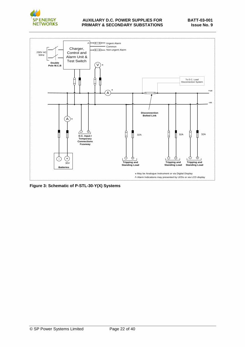
Figure 3: Schematic of P-STL-30-Y(X) Systems
AUXILIARY D.C. POWER SUPPLIES FOR PRIMARY & SECONDARY SUBSTATIONS
BATT-03-001 Issue No. 9
© SP Power Systems Limited Page 23 of 40
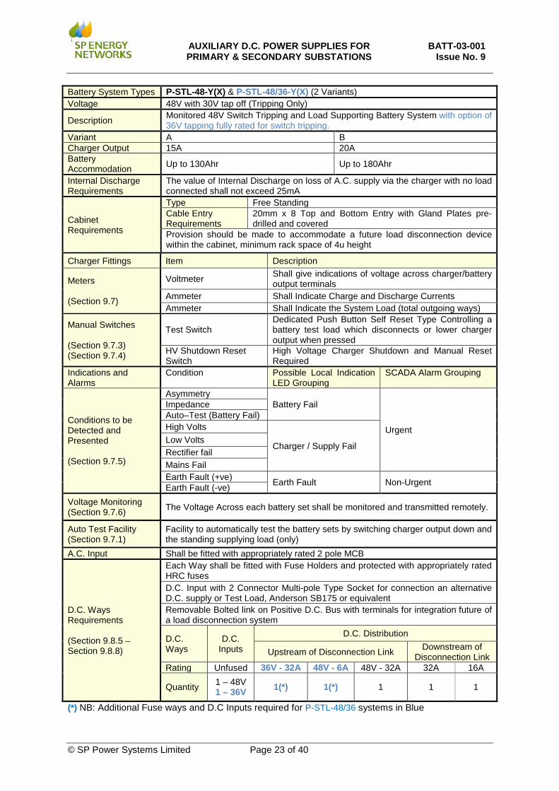
Battery System Types P-STL-48-Y(X) & P-STL-48/36-Y(X) (2 Variants) Voltage 48V with 30V tap off (Tripping Only)
Description Monitored 48V Switch Tripping and Load Supporting Battery System with option of 36V tapping fully rated for switch tripping.
Variant A B Charger Output 15A 20A Battery Accommodation Up to 130Ahr Up to 180Ahr
Internal Discharge Requirements
The value of Internal Discharge on loss of A.C. supply via the charger with no load connected shall not exceed 25mA
Cabinet Requirements
Type Free Standing Cable Entry Requirements
20mm x 8 Top and Bottom Entry with Gland Plates pre-drilled and covered
Provision should be made to accommodate a future load disconnection device within the cabinet, minimum rack space of 4u height
Charger Fittings Item Description
Meters (Section 9.7)
Voltmeter Shall give indications of voltage across charger/battery output terminals
Ammeter Shall Indicate Charge and Discharge Currents Ammeter Shall Indicate the System Load (total outgoing ways)
Manual Switches (Section 9.7.3) (Section 9.7.4)
Test Switch Dedicated Push Button Self Reset Type Controlling a battery test load which disconnects or lower charger output when pressed
HV Shutdown Reset Switch
High Voltage Charger Shutdown and Manual Reset Required
Indications and Alarms
Condition Possible Local Indication LED Grouping
SCADA Alarm Grouping
Conditions to be Detected and Presented (Section 9.7.5)
Asymmetry Battery Fail
Urgent
Impedance Auto–Test (Battery Fail) High Volts
Charger / Supply Fail Low Volts Rectifier fail Mains Fail Earth Fault (+ve) Earth Fault Non-Urgent Earth Fault (-ve)
Voltage Monitoring (Section 9.7.6) The Voltage Across each battery set shall be monitored and transmitted remotely.
Auto Test Facility (Section 9.7.1)
Facility to automatically test the battery sets by switching charger output down and the standing supplying load (only)
A.C. Input Shall be fitted with appropriately rated 2 pole MCB
D.C. Ways Requirements (Section 9.8.5 – Section 9.8.8)
Each Way shall be fitted with Fuse Holders and protected with appropriately rated HRC fuses D.C. Input with 2 Connector Multi-pole Type Socket for connection an alternative D.C. supply or Test Load, Anderson SB175 or equivalent Removable Bolted link on Positive D.C. Bus with terminals for integration future of a load disconnection system
D.C. Ways
D.C. Inputs
D.C. Distribution
Upstream of Disconnection Link Downstream of Disconnection Link
Rating Unfused 36V - 32A 48V - 6A 48V - 32A 32A 16A
Quantity 1 – 48V 1 – 36V 1(*) 1(*) 1 1 1
(*) NB: Additional Fuse ways and D.C Inputs required for P-STL-48/36 systems in Blue
AUXILIARY D.C. POWER SUPPLIES FOR PRIMARY & SECONDARY SUBSTATIONS
BATT-03-001 Issue No. 9
© SP Power Systems Limited Page 24 of 40
Charger, Control and Alarm Unit & Test Switch
+ve
-ve
Tripping and Standing Load
+-
32A
* May be Analogue Instrument or via Digital Display
V *
Alarm Indications may presented by LEDs or via LCD display
^
^
Urgent AlarmCommonNon-urgent Alarm
+-
32AD.C. Input / Temporary
Connections Fuseway
+-
Tripping and Standing Load
+-
16A
Tripping and Standing Load
A*
Disconnection Bolted Link
230V AC50Hz
Double Pole M.C.B
To D.C. Load Disconnection System
+-36V
A
Batteries
*
+48V36V
Tripping
+-
32A
+-
Essential Services
6A
Additional Requirements for the P-STL-48/36 System in Blue
D.C. Input / Temporary
Connections Fuseway
+-
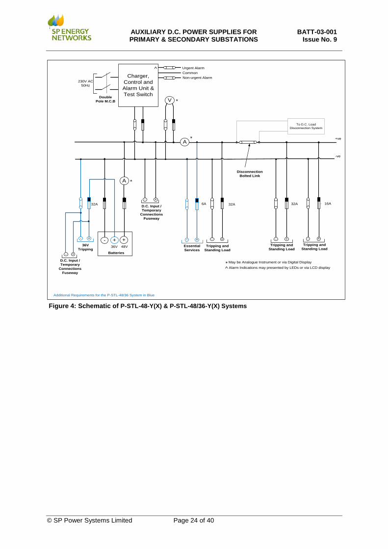
Figure 4: Schematic of P-STL-48-Y(X) & P-STL-48/36-Y(X) Systems
AUXILIARY D.C. POWER SUPPLIES FOR PRIMARY & SECONDARY SUBSTATIONS
BATT-03-001 Issue No. 9
© SP Power Systems Limited Page 25 of 40
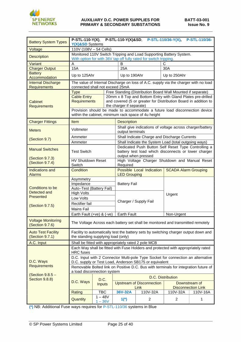
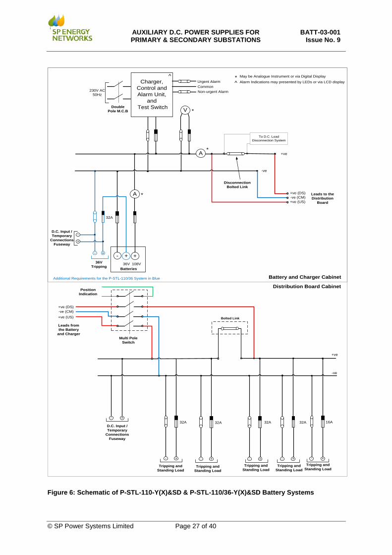
Battery System Types P-STL-110-Y(X), P-STL-110-Y(X)&SD, P-STL-110/36-Y(X), P-STL-110/36-Y(X)&SD Systems
Voltage 110V (108V – 54 Cells)
Description Monitored 110V Switch Tripping and Load Supporting Battery System. With option for with 36V tap off fully rated for switch tripping.
Variant A B C Charger Output 15A 25A 30A Battery Accommodation Up to 125Ahr Up to 190Ahr Up to 250Ahr
Internal Discharge Requirements
The value of Internal Discharge on loss of A.C. supply via the charger with no load connected shall not exceed 25mA
Cabinet Requirements
Type Free Standing (Distribution Board Wall Mounted if separate) Cable Entry Requirements
20mm x 8 Top and Bottom Entry with Gland Plates pre-drilled and covered (5 or greater for Distribution Board in addition to the charger if separate)
Provision should be made to accommodate a future load disconnection device within the cabinet, minimum rack space of 4u height
Charger Fittings Item Description
Meters (Section 9.7)
Voltmeter Shall give indications of voltage across charger/battery output terminals
Ammeter Shall Indicate Charge and Discharge Currents Ammeter Shall Indicate the System Load (total outgoing ways)
Manual Switches (Section 9.7.3) (Section 9.7.4)
Test Switch Dedicated Push Button Self Reset Type Controlling a battery test load which disconnects or lower charger output when pressed
HV Shutdown Reset Switch
High Voltage Charger Shutdown and Manual Reset Required
Indications and Alarms
Condition Possible Local Indication LED Grouping
SCADA Alarm Grouping
Conditions to be Detected and Presented (Section 9.7.5)
Asymmetry Battery Fail
Urgent
Impedance Auto–Test (Battery Fail) High Volts
Charger / Supply Fail Low Volts Rectifier fail Mains Fail Earth Fault (+ve) & (-ve) Earth Fault Non-Urgent
Voltage Monitoring (Section 9.7.6) The Voltage Across each battery set shall be monitored and transmitted remotely
Auto Test Facility (Section 9.7.1)
Facility to automatically test the battery sets by switching charger output down and the standing supplying load (only)
A.C. Input Shall be fitted with appropriately rated 2 pole MCB
D.C. Ways Requirements (Section 9.8.5 – Section 9.8.8)
Each Way shall be fitted with Fuse Holders and protected with appropriately rated HRC fuses D.C. Input with 2 Connector Multi-pole Type Socket for connection an alternative D.C. supply or Test Load, Anderson SB175 or equivalent Removable Bolted link on Positive D.C. Bus with terminals for integration future of a load disconnection system
D.C. Ways D.C. Inputs
D.C. Distribution Upstream of Disconnection
Link Downstream of
Disconnection Link Rating TBC 36V-32A 110V-32A 110V-32A 110V-16A
Quantity 1 – 48V 1 – 36V 1(*) 2 2 1
(*) NB: Additional Fuse ways requires for P-STL-110/36 systems in Blue
AUXILIARY D.C. POWER SUPPLIES FOR PRIMARY & SECONDARY SUBSTATIONS
BATT-03-001 Issue No. 9
© SP Power Systems Limited Page 26 of 40
Charger, Control and Alarm Unit,
and Test Switch
+-
A
+ve
-ve
Batteries
+-
*
* May be Analogue Instrument or via Digital Display
V *
Alarm Indications may presented by LEDs or via LCD display^
Urgent AlarmCommonNon-urgent Alarm
+-
32AD.C. Input / Temporary
Connections Fuseway
+-
Tripping and Standing Load
+-
16A
Tripping and Standing Load
A*
Disconnection Bolted Link
230V AC50Hz
Double Pole M.C.B
To D.C. Load Disconnection System
+-
^
Tripping and Standing Load
Tripping and Standing Load
32A32A
36V Tripping
+- +
32A
Additional Requirements for the P-STL-110/36 System in Blue
108V36V
+-
Tripping and Standing Load
32A
D.C. Input / Temporary
Connections Fuseway
+-
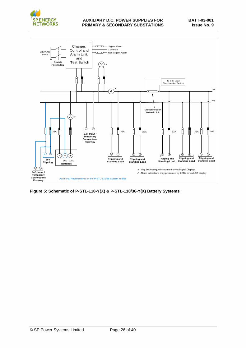
Figure 5: Schematic of P-STL-110-Y(X) & P-STL-110/36-Y(X) Battery Systems
AUXILIARY D.C. POWER SUPPLIES FOR PRIMARY & SECONDARY SUBSTATIONS
BATT-03-001 Issue No. 9
© SP Power Systems Limited Page 27 of 40
Charger, Control and Alarm Unit,
and Test Switch
+-
A
+ve
-ve
Batteries
*
* May be Analogue Instrument or via Digital Display
V *
Alarm Indications may presented by LEDs or via LCD display^Urgent AlarmCommonNon-urgent Alarm
A*
Disconnection Bolted Link
230V AC50Hz
Double Pole M.C.B
To D.C. Load Disconnection System
^
36V Tripping
+- +
32A
Additional Requirements for the P-STL-110/36 System in Blue
108V36V
D.C. Input / Temporary
Connections Fuseway
+-
Leads to the Distribution
Board
+ve (DS)
+ve (US)-ve (CM)
+ve
-ve
+- +-
32AD.C. Input / Temporary
Connections Fuseway
+-
Tripping and Standing Load
+-
16A
Tripping and Standing Load
+-
Tripping and Standing Load
Tripping and Standing Load
32A32A
+-
Tripping and Standing Load
32A
Bolted Link
Multi Pole Switch
+ve (DS)
+ve (US)-ve (CM)
Leads from the Battery
and Charger
Position Indication
Battery and Charger Cabinet
Distribution Board Cabinet
Figure 6: Schematic of P-STL-110-Y(X)&SD & P-STL-110/36-Y(X)&SD Battery Systems
AUXILIARY D.C. POWER SUPPLIES FOR PRIMARY & SECONDARY SUBSTATIONS
BATT-03-001 Issue No. 9
© SP Power Systems Limited Page 28 of 40
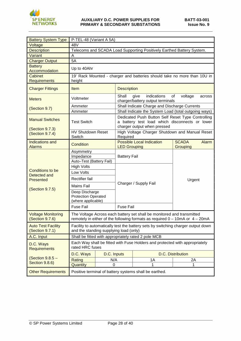
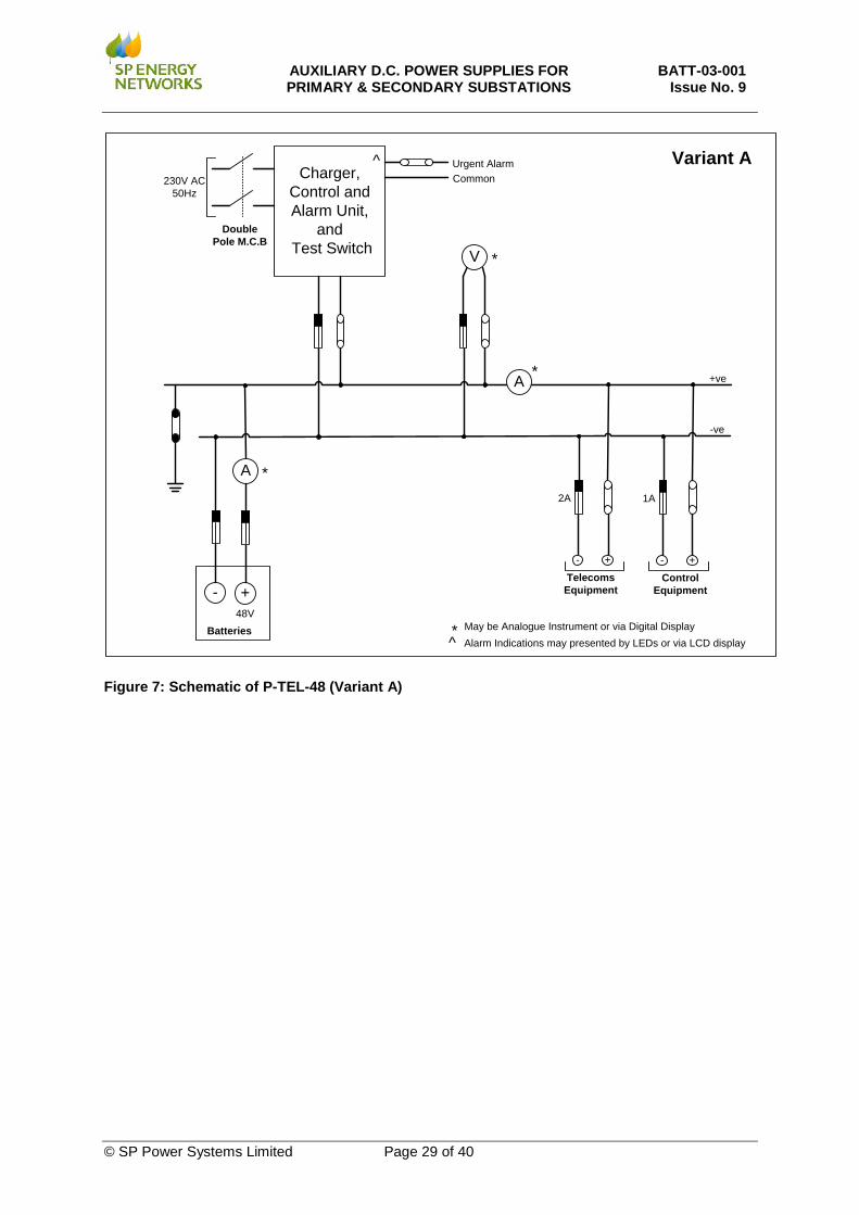
Battery System Type P-TEL-48 (Variant A 5A) Voltage 48V Description Telecoms and SCADA Load Supporting Positively Earthed Battery System. Variant A Charger Output 5A Battery Accommodation Up to 40Ahr
Cabinet Requirements
19’ Rack Mounted - charger and batteries should take no more than 10U in height
Charger Fittings Item Description
Meters (Section 9.7)
Voltmeter Shall give indications of voltage across charger/battery output terminals
Ammeter Shall Indicate Charge and Discharge Currents Ammeter Shall Indicate the System Load (total outgoing ways)
Manual Switches (Section 9.7.3) (Section 9.7.4)
Test Switch Dedicated Push Button Self Reset Type Controlling a battery test load which disconnects or lower charger output when pressed
HV Shutdown Reset Switch
High Voltage Charger Shutdown and Manual Reset Required
Indications and Alarms Condition Possible Local Indication
LED Grouping SCADA Alarm Grouping
Conditions to be Detected and Presented (Section 9.7.5)
Asymmetry Battery Fail
Urgent
Impedance Auto–Test (Battery Fail) High Volts
Charger / Supply Fail
Low Volts Rectifier fail
Mains Fail Deep Discharge Protection Operated (where applicable) Fuse Fail Fuse Fail
Voltage Monitoring (Section 9.7.6)
The Voltage Across each battery set shall be monitored and transmitted remotely in either of the following formats as required 0 – 10mA or 4 – 20mA
Auto Test Facility (Section 9.7.1)
Facility to automatically test the battery sets by switching charger output down and the standing supplying load (only)
A.C. Input Shall be fitted with appropriately rated 2 pole MCB
D.C. Ways Requirements (Section 9.8.5 – Section 9.8.6)
Each Way shall be fitted with Fuse Holders and protected with appropriately rated HRC fuses D.C. Ways D.C. Inputs D.C. Distribution Rating N/A 1A 2A Quantity 0 1 1
Other Requirements Positive terminal of battery systems shall be earthed.
AUXILIARY D.C. POWER SUPPLIES FOR PRIMARY & SECONDARY SUBSTATIONS
BATT-03-001 Issue No. 9
© SP Power Systems Limited Page 29 of 40
Charger, Control and Alarm Unit,
and Test Switch
+-48V
A
+ve
-ve
Batteries
*
May be Analogue Instrument or via Digital Display
*
Alarm Indications may presented by LEDs or via LCD display
^
+-
1A
Control Equipment
V
A *
230V AC50Hz
Double Pole M.C.B
Urgent AlarmCommon
^*
Variant A
+-
2A
Telecoms Equipment
Figure 7: Schematic of P-TEL-48 (Variant A)
AUXILIARY D.C. POWER SUPPLIES FOR PRIMARY & SECONDARY SUBSTATIONS
BATT-03-001 Issue No. 9
© SP Power Systems Limited Page 30 of 40
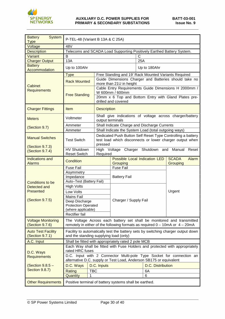
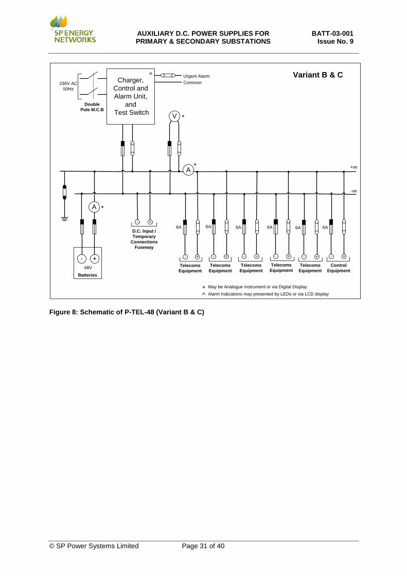
Battery System Type P-TEL-48 (Variant B 13A & C 25A)
Voltage 48V Description Telecoms and SCADA Load Supporting Positively Earthed Battery System. Variant B C Charger Output 13A 25A Battery Accommodation Up to 100Ahr Up to 180Ahr
Cabinet Requirements
Type Free Standing and 19’ Rack Mounted Variants Required
Rack Mounted Guide Dimensions Charger and Batteries should take no more than 21U in height
Free Standing
Cable Entry Requirements Guide Dimensions H 2000mm / W 600mm / 600mm 20mm x 6 Top and Bottom Entry with Gland Plates pre-drilled and covered
Charger Fittings Item Description
Meters (Section 9.7)
Voltmeter Shall give indications of voltage across charger/battery output terminals
Ammeter Shall Indicate Charge and Discharge Currents Ammeter Shall Indicate the System Load (total outgoing ways)
Manual Switches (Section 9.7.3) (Section 9.7.4)
Test Switch Dedicated Push Button Self Reset Type Controlling a battery test load which disconnects or lower charger output when pressed
HV Shutdown Reset Switch
High Voltage Charger Shutdown and Manual Reset Required
Indications and Alarms Condition Possible Local Indication LED
Grouping SCADA Alarm Grouping
Conditions to be Detected and Presented (Section 9.7.5)
Fuse Fail Fuse Fail
Urgent
Asymmetry Battery Fail Impedance
Auto–Test (Battery Fail) High Volts
Charger / Supply Fail
Low Volts Mains Fail Deep Discharge Protection Operated (where applicable) Rectifier fail
Voltage Monitoring (Section 9.7.6)
The Voltage Across each battery set shall be monitored and transmitted remotely in either of the following formats as required 0 – 10mA or 4 – 20mA
Auto Test Facility (Section 9.7.1)
Facility to automatically test the battery sets by switching charger output down and the standing supplying load (only)
A.C. Input Shall be fitted with appropriately rated 2 pole MCB
D.C. Ways Requirements (Section 9.8.5 – Section 9.8.7)
Each Way shall be fitted with Fuse Holders and protected with appropriately rated HRC fuses D.C. Input with 2 Connector Multi-pole Type Socket for connection an alternative D.C. supply or Test Load, Anderson SB175 or equivalent D.C. Ways D.C. Inputs D.C. Distribution Rating TBC 6A Quantity 1 6
Other Requirements Positive terminal of battery systems shall be earthed.
AUXILIARY D.C. POWER SUPPLIES FOR PRIMARY & SECONDARY SUBSTATIONS
BATT-03-001 Issue No. 9
© SP Power Systems Limited Page 31 of 40
Charger, Control and Alarm Unit,
and Test Switch
+-48V
A
+ve
-ve
Telecoms Equipment
Batteries
+-
6A
*
* May be Analogue Instrument or via Digital Display
*
Alarm Indications may presented by LEDs or via LCD display
^
^
Telecoms Equipment
+-
6A
+-
6A
Telecoms Equipment
D.C. Input / Temporary
Connections Fuseway
+-
V
A *
230V AC50Hz
Double Pole M.C.B
Urgent AlarmCommon
+-
Telecoms Equipment
6A
Variant B & C
+-
6A
+-
6A
Telecoms Equipment
Control Equipment
Figure 8: Schematic of P-TEL-48 (Variant B & C)

AUXILIARY D.C. POWER SUPPLIES FOR PRIMARY & SECONDARY SUBSTATIONS
BATT-03-001 Issue No. 9
© SP Power Systems Limited Page 32 of 40
11. WORKS INSPECTION
On receipt of the order, the Tenderer shall immediately agree with the Company a provisional dated programme for witnessing of the works testing and inspection. The Company require a minimum of three weeks’ notice to confirm the test and inspection programme date.
12. COMMISSIONING, OPERATION AND MAINTENANCE MANUAL
A Commissioning, Operation and Maintenance Manual shall be provided with each charger. The manual shall include a copy of the following drawings:
• Wiring diagram for the complete equipment; • Circuit diagram for the charger chassis, detailing the value and types of the electronic
components. Such components may alternatively be detailed on a separate component list; • Circuit diagram for the high/low voltage relay; • Full test instructions for provision all required alarm function on site at time of commissioning
and any future maintenance / fault faulting; • A general fault finding guide.
The manuals/drawings shall be approved by the Engineer
13. APPROVAL
Following approval of any item, no change shall be made by the manufacturer without the written agreement of the Engineer.
14. QUALITY REQUIREMENTS
Analysis of defective items on receipt and in use will be used to assist in subsequent tender analysis.
14.1 Quality Assurance
Manufacturers shall operate a fully documented quality assurance system, and should indicate with their tenders the QA Approvals granted to the manufacturer.
14.2 Progress and Inspection Requirements
Access to the supplier's or Sub-Contractor's works shall be granted, at any reasonable time, to allow the engineering staff to verify the progress status of the work.
14.3 Quality Plans/Inspection Checklists
The supplier shall submit to the Company, before the commencement of design/manufacture, quality plans/inspection checklists for "mark-up" of the Company's requirements with respect to document approval and quality control activities. Two copies of all approved documents shall be supplied to the Company.
14.4 Inspection and Witnessing of Tests
The Engineer shall carry out, where appropriate, inspections and witness routine tests in accordance with the "mark-up" on the approved quality plans/inspection checklists and agreed test programme. The supplier shall give seven days’ notice of his intention to carry out any witness points referenced on the quality plans/inspection checklists.
AUXILIARY D.C. POWER SUPPLIES FOR PRIMARY & SECONDARY SUBSTATIONS
BATT-03-001 Issue No. 9
© SP Power Systems Limited Page 33 of 40
14.5 Retention of Quality Records
The supplier shall maintain the quality records in an area of safe deposit for a minimum period of 10 years and not dispose of these records without prior agreement of the Company. During the retention period, copies of the quality records shall be made available to the Company on request.
14.6 Certificate of Conformance
The supplier shall provide a certificate of conformance for each item that required a quality plan/inspection checklist and will be signed by the supplier's nominated representative. This document shall reference the quality plan/inspection checklist, the quality records being retained, the supplier's unique identification and the Company's order number. In addition, any certification required to meet the statutory requirements for pressure parts/lifting equipment shall be issued with the certificate of conformance. One copy of the certificate of conformance and, where relevant, the statutory certification shall be despatched with the item and a second copy issued to the Company. A certificate of conformance shall be provided upon completion of each order placed with the successful Tenderer(s), identifying the appropriate technical specifications with which the items comply. The Tenderer shall submit the following documents with the tender:
• Overall quality policy statement; • Copies of any formal quality approvals; and • Quality plans for each item offered (these must identify the control stages during manufacture
and test).
15. PROTECTION AND PACKAGING
The Supplier shall ensure that each item is suitably protected and packaged to maintain it “fit for service” before installation.
16. DELIVERY
Tenderers shall state on the Price Schedule the lead times offered on all items.
AUXILIARY D.C. POWER SUPPLIES FOR PRIMARY & SECONDARY SUBSTATIONS
BATT-03-001 Issue No. 9
© SP Power Systems Limited Page 34 of 40
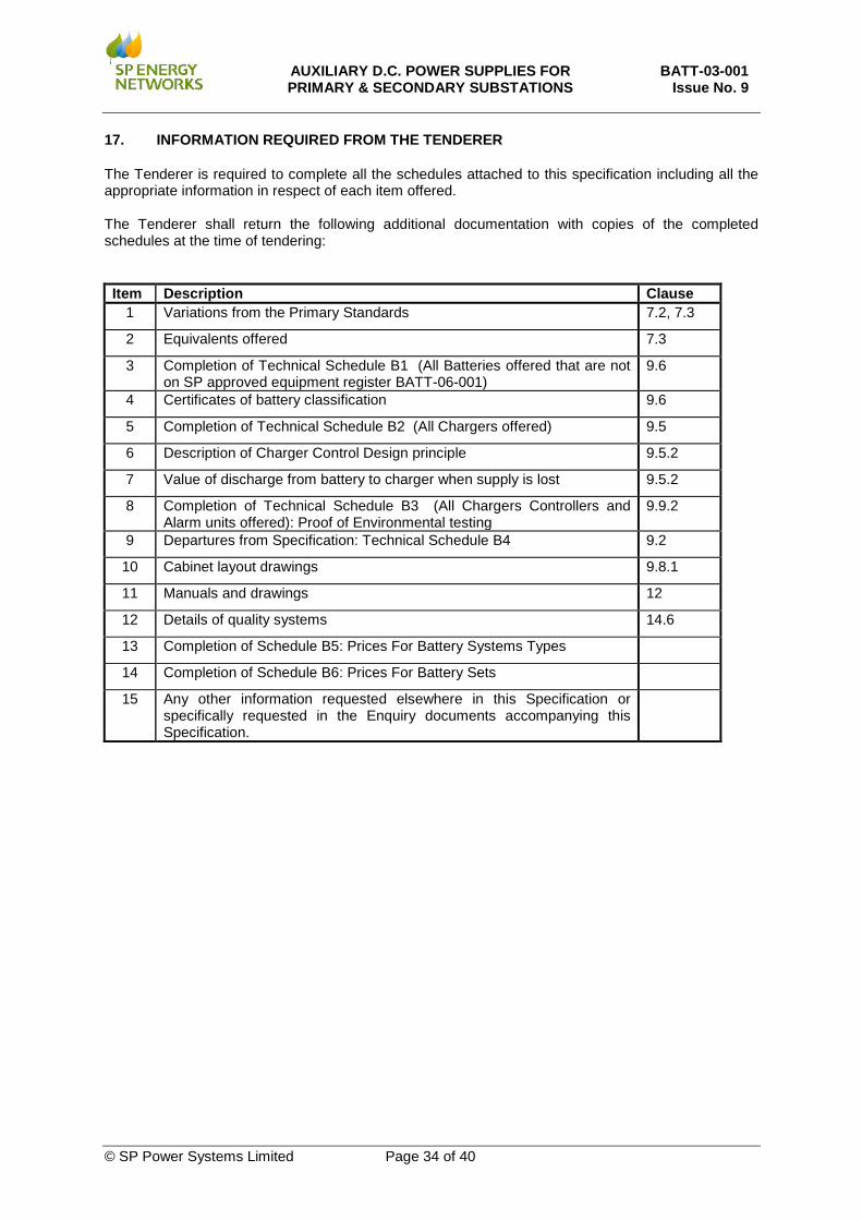
17. INFORMATION REQUIRED FROM THE TENDERER
The Tenderer is required to complete all the schedules attached to this specification including all the appropriate information in respect of each item offered. The Tenderer shall return the following additional documentation with copies of the completed schedules at the time of tendering:
Item Description Clause 1 Variations from the Primary Standards 7.2, 7.3
2 Equivalents offered 7.3
3 Completion of Technical Schedule B1 (All Batteries offered that are not on SP approved equipment register BATT-06-001)
9.6
4 Certificates of battery classification 9.6
5 Completion of Technical Schedule B2 (All Chargers offered) 9.5
6 Description of Charger Control Design principle 9.5.2
7 Value of discharge from battery to charger when supply is lost 9.5.2
8 Completion of Technical Schedule B3 (All Chargers Controllers and Alarm units offered): Proof of Environmental testing
9.9.2
9 Departures from Specification: Technical Schedule B4 9.2
10 Cabinet layout drawings 9.8.1
11 Manuals and drawings 12
12 Details of quality systems 14.6
13 Completion of Schedule B5: Prices For Battery Systems Types
14 Completion of Schedule B6: Prices For Battery Sets
15 Any other information requested elsewhere in this Specification or specifically requested in the Enquiry documents accompanying this Specification.
AUXILIARY D.C. POWER SUPPLIES FOR PRIMARY & SECONDARY SUBSTATIONS
BATT-03-001 Issue No. 9
© SP Power Systems Limited Page 35 of 40
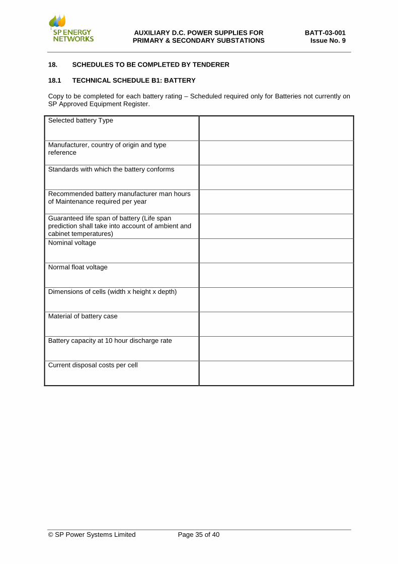
18. SCHEDULES TO BE COMPLETED BY TENDERER
18.1 TECHNICAL SCHEDULE B1: BATTERY
Copy to be completed for each battery rating – Scheduled required only for Batteries not currently on SP Approved Equipment Register. Selected battery Type
Manufacturer, country of origin and type reference
Standards with which the battery conforms
Recommended battery manufacturer man hours of Maintenance required per year
Guaranteed life span of battery (Life span prediction shall take into account of ambient and cabinet temperatures)
Nominal voltage
Normal float voltage
Dimensions of cells (width x height x depth)
Material of battery case
Battery capacity at 10 hour discharge rate
Current disposal costs per cell
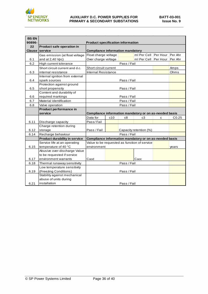
AUXILIARY D.C. POWER SUPPLIES FOR PRIMARY & SECONDARY SUBSTATIONS
BATT-03-001 Issue No. 9
© SP Power Systems Limited Page 36 of 40
Product safe operation in service
ml Per Cell Per Hour Per Ahrml Per Cell Per Hour Per Ahr
6.2 High current toleranceAmpsOhms
6.4Internal ignition from external spark sources
6.5Protection against ground short propensity
6.6Content and durability of required markings
6.7 Material identification6.8 Valve operation
Product performance in service
Data for c10 c8 c3 c C0.25Pass/ Fail
6.12Charge retention during storage Pass / Fail
6.14 Recharge behaviourProduct durability in service
6.15Service life at an operating temperature of 40 °C years
6.17
Abusive over-discharge Value to be requested if service environment warrants Caod Caoc
6.18 Thermal runaway sensitivity
6.19Low temperature sensitivity (Freezing Conditions)
6.21
Stability against mechanical abuse of units during installation
6.11 Discharge capacity
Pass / Fail
Pass / Fail
Pass / FailPass / FailPass / Fail
Pass / Fail
Value to be requested as function of service environment
Compliance information mandatory or on as-needed basis
Float charge voltageOver charge voltage
Pass / Fail
Pass / Fail
Compliance information mandatory or on as-needed basisPass / FailCapacity retention (%)
BS EN 90896-
22 Clause
6.1
6.3
Product specification information
Compliance information mandatoryGas emission (at float voltage and at 2,40 Vpc)
Short circuit current and d.c. internal resistance
Short circuit currentInternal Resistance
Pass / Fail
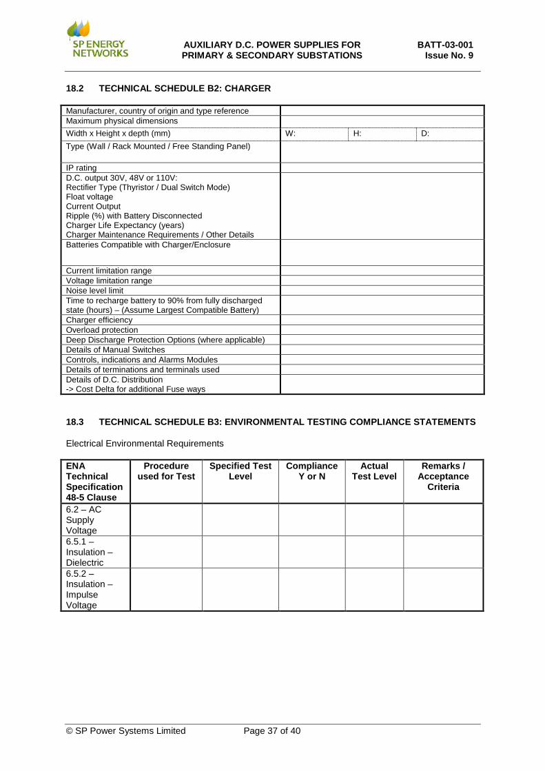
AUXILIARY D.C. POWER SUPPLIES FOR PRIMARY & SECONDARY SUBSTATIONS
BATT-03-001 Issue No. 9
© SP Power Systems Limited Page 37 of 40
18.2 TECHNICAL SCHEDULE B2: CHARGER
Manufacturer, country of origin and type reference Maximum physical dimensions Width x Height x depth (mm) W: H: D: Type (Wall / Rack Mounted / Free Standing Panel)
IP rating D.C. output 30V, 48V or 110V: Rectifier Type (Thyristor / Dual Switch Mode) Float voltage Current Output Ripple (%) with Battery Disconnected Charger Life Expectancy (years) Charger Maintenance Requirements / Other Details
Batteries Compatible with Charger/Enclosure
Current limitation range Voltage limitation range Noise level limit Time to recharge battery to 90% from fully discharged state (hours) – (Assume Largest Compatible Battery)
Charger efficiency Overload protection Deep Discharge Protection Options (where applicable) Details of Manual Switches Controls, indications and Alarms Modules Details of terminations and terminals used Details of D.C. Distribution -> Cost Delta for additional Fuse ways
18.3 TECHNICAL SCHEDULE B3: ENVIRONMENTAL TESTING COMPLIANCE STATEMENTS
Electrical Environmental Requirements ENA Technical Specification 48-5 Clause
Procedure used for Test
Specified Test Level
Compliance Y or N
Actual Test Level
Remarks / Acceptance
Criteria
6.2 – AC Supply Voltage
6.5.1 –Insulation –Dielectric
6.5.2 –Insulation –Impulse Voltage
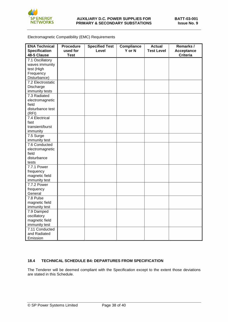
AUXILIARY D.C. POWER SUPPLIES FOR PRIMARY & SECONDARY SUBSTATIONS
BATT-03-001 Issue No. 9
© SP Power Systems Limited Page 38 of 40
Electromagnetic Compatibility (EMC) Requirements ENA Technical Specification 48-5 Clause
Procedure used for
Test
Specified Test Level
Compliance Y or N
Actual Test Level
Remarks / Acceptance
Criteria 7.1 Oscillatory waves immunity test (High Frequency Disturbance)
7.2 Electrostatic Discharge immunity tests
7.3 Radiated electromagnetic field disturbance test (RFI)
7.4 Electrical fast transient/burst immunity
7.5 Surge immunity test
7.6 Conducted electromagnetic field disturbance tests
7.7.1 Power frequency magnetic field immunity test
7.7.2 Power frequency General
7.8 Pulse magnetic field immunity test
7.9 Damped oscillatory magnetic field immunity test
7.11 Conducted and Radiated Emission
18.4 TECHNICAL SCHEDULE B4: DEPARTURES FROM SPECIFICATION
The Tenderer will be deemed compliant with the Specification except to the extent those deviations are stated in this Schedule.
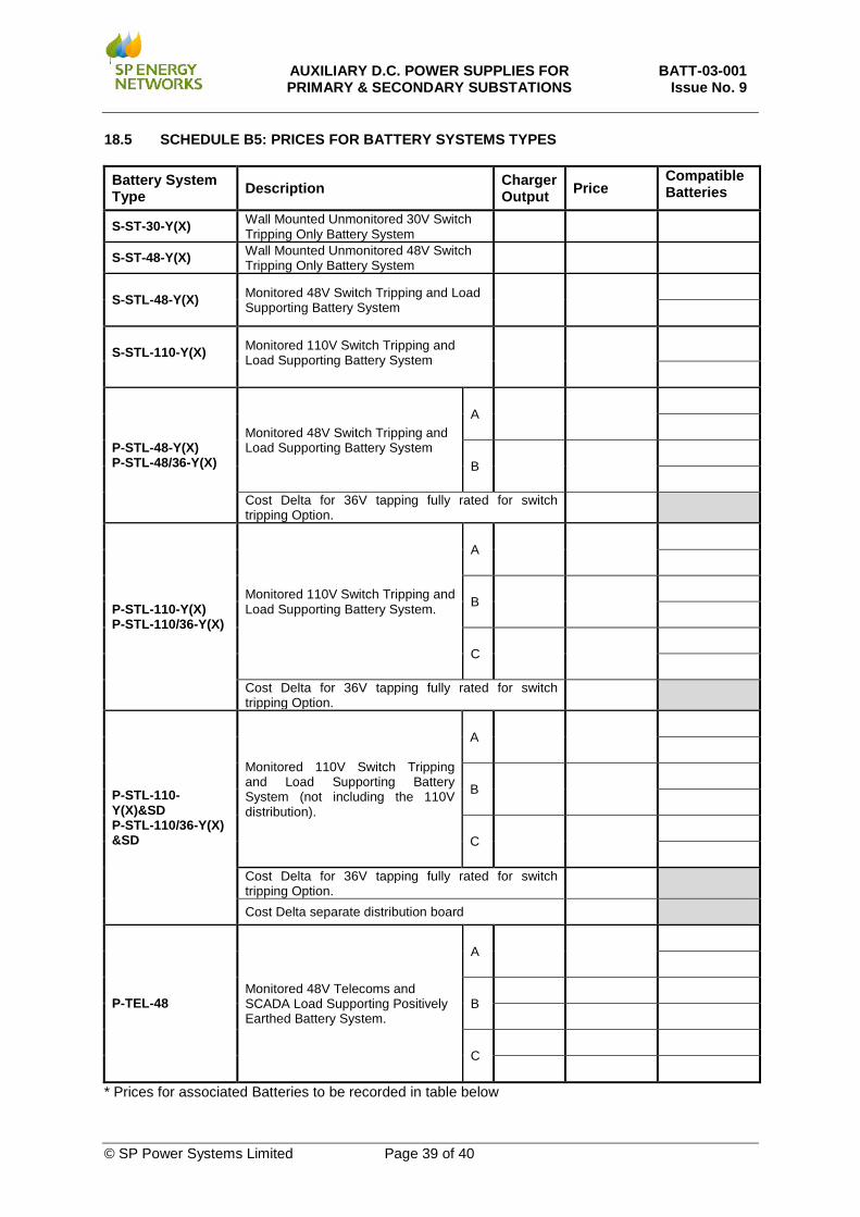
AUXILIARY D.C. POWER SUPPLIES FOR PRIMARY & SECONDARY SUBSTATIONS
BATT-03-001 Issue No. 9
© SP Power Systems Limited Page 39 of 40
18.5 SCHEDULE B5: PRICES FOR BATTERY SYSTEMS TYPES
Battery System Type Description Charger
Output Price Compatible Batteries
S-ST-30-Y(X) Wall Mounted Unmonitored 30V Switch Tripping Only Battery System
S-ST-48-Y(X) Wall Mounted Unmonitored 48V Switch Tripping Only Battery System
S-STL-48-Y(X) Monitored 48V Switch Tripping and Load Supporting Battery System
S-STL-110-Y(X) Monitored 110V Switch Tripping and Load Supporting Battery System
P-STL-48-Y(X) P-STL-48/36-Y(X)
Monitored 48V Switch Tripping and Load Supporting Battery System
A
B
Cost Delta for 36V tapping fully rated for switch tripping Option.
P-STL-110-Y(X) P-STL-110/36-Y(X)
Monitored 110V Switch Tripping and Load Supporting Battery System.
A
B
C
Cost Delta for 36V tapping fully rated for switch tripping Option.
P-STL-110-Y(X)&SD P-STL-110/36-Y(X) &SD
Monitored 110V Switch Tripping and Load Supporting Battery System (not including the 110V distribution).
A
B
C
Cost Delta for 36V tapping fully rated for switch tripping Option.
Cost Delta separate distribution board
P-TEL-48 Monitored 48V Telecoms and SCADA Load Supporting Positively Earthed Battery System.
A
B
C
* Prices for associated Batteries to be recorded in table below
AUXILIARY D.C. POWER SUPPLIES FOR PRIMARY & SECONDARY SUBSTATIONS
BATT-03-001 Issue No. 9
© SP Power Systems Limited Page 40 of 40
18.6 SCHEDULE B6: PRICES FOR BATTERY SETS
Battery Price
Compatible Battery Systems (Battery/Charger System Reference) Manufacturer Series Model Voltage
(per Block) Voltage (of Set)