Embed Size (px)
Citation preview

[AK4708]
MS0618-E-01 2009/09 - 1 -
GENERAL DESCRIPTION The AK4708 is an IIC controlled audio and video switch matrix designed for digital TV and set-top-box applications. The AK4708 offers the ideal features for digital set-top-box systems. The AK4708 includes the audio switches, video switches, video filters. The AK4708 provides high performance audio and video routings to meet dual SCART connections. The AK4708 is supplied in a small 48-pin LQFP package to contribute space saving in PCB.
FEATURES Analog Switches for SCART
Audio section THD+N: −86dB (@2Vrms) Dynamic Range: 96dB (@2Vrms) Analog Inputs Two Full Differential Stereo Inputs or Single-ended input for Decoder DAC Two Stereo Inputs (TV & VCR SCART) Analog Outputs Two Stereo Outputs (TV & VCR SCART) Stereo Analog Volume with Pop-noise Free Circuit (+6dB to –60dB & Mute) Pop Noise Free Circuit for Power on/off
Video section VCR SCART supports RGB mode Integrated LPF: −40dB@27MHz 75Ω driver 6dB Gain for Outputs Four CVBS/Y inputs (ENCx2, TV, VCR), Two CVBS/Y outputs (TV, VCR) Three R/C inputs (ENCx2, VCR), Two R/C outputs (TV, VCR) Two G and B inputs (ENC, VCR), Two G and B outputs (TV, VCR)
TV/VCR input monitor Loop-through Mode for standby Auto-Startup Mode for power saving SCART pin#16 (Fast Blanking), pin#8 (Slow Blanking) Control
Power supply 5V+/−5% and 12V+/−10% Small current consumption in Standby Mode
(VD=10μA typ., VVD1+VVD2=10μA typ., VP=10μA typ.) Package
48-pin LQFP
AV SCART Switch with Two RGB OutputsAK4708

[AK4708]
MS0618-E-01 2009/09 - 2 -
Block Diagram
TVOUTL
TVOUTR
VCROUTL
VCROUTR
TVINL
TVINR
VCRINL
VCRINR
AINL+
AINL-
AINR-
AINR+
Bias
TV1-0
MONO
SCL
SDA
Register
Control
PDN
PVCOM
VD
VCR1-0
VMONO
DVCOM
VP
AMP
VSS
-6dB to +12dB
(3dB/step)
Volume #0
+6 to -60dB
(2dB/step)
Volume #1
Audio Block

[AK4708]
MS0618-E-01 2009/09 - 3 -
ENC C TVRC
ENC G/CVBS
VCR G TVG
ENC B/Pb
VCR B/Pb TVB
ENC Y TVVOUT
6dB
ENC R/C/Pr
VCRVOUT
VCRC
VCR CVBS/Y
TV CVBS
VCR R/C/Pr
ENC CVBS/Y
ENCC
ENCG
VCRG
ENCB
VCRB
ENCY
ENCRC
VCRVIN
TVVIN
VCRRC
ENCV
( Typical connection )
TV SCART
VCR SCART
( Typical connection )
VVD2
VVSS
VVD1Monitor
6dB
6dB
VCRGO
VCRBO
6dB
6dB
6dB
6dB
6dB
Video Block

[AK4708]
MS0618-E-01 2009/09 - 4 -
Monitor
VCR FB
TVFB 6dB
0V
2V
TVSB
VCRSB
0/ 6/ 12V
0/ 6/ 12V
VCRFB
( Typical connection )
TV SCART
VCR SCART
( Typical connection )
INT
6dB
0V
2V VCRFBO
Video Blanking Block

[AK4708]
MS0618-E-01 2009/09 - 5 -
Ordering Guide
AK4708EQ -10 ∼ +70°C 48pin LQFP (0.5mm pitch) AKD4708 Evaluation board for AK4708
Pin Layout
VD
37
VCRBO
36
38 AINR+
39 AINL-
40 AINL+
41 SCL
42
43
SDA
44
PDN
45 VCRGO
46 VCRFBO
47
VSS
35 34 33 32 31 30 29 28 27 26
VCR
C1
VVS
S2
TVVO
UT
3
VVD
24
TVR
C5
TVG
6
TVB
7
VVD
18
ENC
B9
EN
CG
10
ENC
RC
11
23
22
21
20
19
18
17
16
15
14
13
TVVIN
ENCY
ENCV
Top View
VCRVOUT
48
EN
CC
12
24
25
TVFB
AINR-
AK4708
VCRFB
VCRVIN
VCRG
VCRRC
INT
VCRB
VCRSB
TVSB
VCRINR
TVO
UTL
TVO
UTR
VCR
OU
TL
VC
RO
UTR
TVIN
L
TVIN
R
VCR
INL
PV
CO
M
DVC
OM
VP
[AK4708]
MS0618-E-01 2009/09 - 6 -
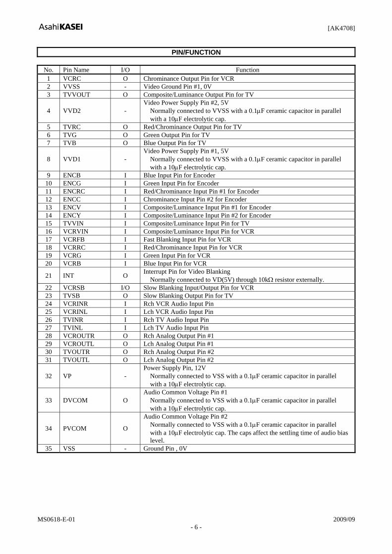
PIN/FUNCTION
No. Pin Name I/O Function 1 VCRC O Chrominance Output Pin for VCR 2 VVSS - Video Ground Pin #1, 0V 3 TVVOUT O Composite/Luminance Output Pin for TV
4 VVD2 - Video Power Supply Pin #2, 5V
Normally connected to VVSS with a 0.1μF ceramic capacitor in parallel with a 10μF electrolytic cap.
5 TVRC O Red/Chrominance Output Pin for TV 6 TVG O Green Output Pin for TV 7 TVB O Blue Output Pin for TV
8 VVD1 - Video Power Supply Pin #1, 5V
Normally connected to VVSS with a 0.1μF ceramic capacitor in parallel with a 10μF electrolytic cap.
9 ENCB I Blue Input Pin for Encoder 10 ENCG I Green Input Pin for Encoder 11 ENCRC I Red/Chrominance Input Pin #1 for Encoder 12 ENCC I Chrominance Input Pin #2 for Encoder 13 ENCV I Composite/Luminance Input Pin #1 for Encoder 14 ENCY I Composite/Luminance Input Pin #2 for Encoder 15 TVVIN I Composite/Luminance Input Pin for TV 16 VCRVIN I Composite/Luminance Input Pin for VCR 17 VCRFB I Fast Blanking Input Pin for VCR 18 VCRRC I Red/Chrominance Input Pin for VCR 19 VCRG I Green Input Pin for VCR 20 VCRB I Blue Input Pin for VCR
21 INT O Interrupt Pin for Video Blanking Normally connected to VD(5V) through 10kΩ resistor externally.
22 VCRSB I/O Slow Blanking Input/Output Pin for VCR 23 TVSB O Slow Blanking Output Pin for TV 24 VCRINR I Rch VCR Audio Input Pin 25 VCRINL I Lch VCR Audio Input Pin 26 TVINR I Rch TV Audio Input Pin 27 TVINL I Lch TV Audio Input Pin 28 VCROUTR O Rch Analog Output Pin #1 29 VCROUTL O Lch Analog Output Pin #1 30 TVOUTR O Rch Analog Output Pin #2 31 TVOUTL O Lch Analog Output Pin #2
32 VP - Power Supply Pin, 12V
Normally connected to VSS with a 0.1μF ceramic capacitor in parallel with a 10μF electrolytic cap.
33 DVCOM O Audio Common Voltage Pin #1
Normally connected to VSS with a 0.1μF ceramic capacitor in parallel with a 10μF electrolytic cap.
34 PVCOM O
Audio Common Voltage Pin #2 Normally connected to VSS with a 0.1μF ceramic capacitor in parallel with a 10μF electrolytic cap. The caps affect the settling time of audio bias level.
35 VSS - Ground Pin , 0V

[AK4708]
MS0618-E-01 2009/09 - 7 -
PIN/FUNCTION (Continued)
No. Pin Name I/O Function
36 VD - Power Supply Pin, 5V
Normally connected to VSS with a 0.1μF ceramic capacitor in parallel with a 10μF electrolytic cap.
37 AINR− I Rch Negative Analog Input Pin 38 AINR+ I Rch Positive Analog Input Pin 39 AINL− I Lch Negative Analog Input Pin 40 AINL+ I Lch Positive Analog Input Pin 41 SCL I Control Data Clock Pin 42 SDA I/O Control Data Pin
43 PDN I Power-Down Mode Pin
When at “L”, the AK4708 is in the power-down mode and is held in reset. The AK4708 should always be reset upon power-up.
44 VCRBO O Blue Output Pin for VCR 45 VCRGO O Green Output Pin for VCR 46 VCRFBO O Fast Blanking Output Pin for VCR 47 VCRVOUT O Composite/Luminance Output Pin for VCR 48 TVFB O Fast Blanking Output Pin for TV
Note: All digital input pins should not be left floating.

[AK4708]
MS0618-E-01 2009/09 - 8 -
INTERNAL EQUIVALENT CIRCUIT Pin No. Pin Name Type Equivalent Circuit Description
41 43
SCL PDN
Digital IN
VD
200
VSS
38 37 39 40
AINR+ AINR− AINL− AINL+
Audio IN
VD
150K
VSS
42 SDA Digital I/O
VD
VSS
200
I2C Bus voltage must not exceed VD.
21 INT Digital OUT
VSS
VVD1
Normally connected to VD(5V) through 10kΩ resister externally.
47 48 3 5 6 7 1
44 45 46
VCRVOUT
TVFB TVVOUT
TVRC TVG TVB
VCRC VCRGO VCRBO
VCRFBO
Video OUT
VVD2
VVSS1
VVD2
VVSS2

[AK4708]
MS0618-E-01 2009/09 - 9 -
Pin No. Pin Name Type Equivalent Circuit Description
9 10 11 12 13 14 15 16 17 18 19 20
ENCB ENCG
ENCRC ENCC ENCV ENCY TVVIN
VCRVIN VCRFB VCRRC VCRG VCRB
Video IN
VVD1
200
VVSS
(60K)
The 60kΩ is attached for Chrominance input.
22 23
VCRSB TVSB Video SB
VP
VVSS
VP
VVSS VVSS
200
(120k)
The 120kΩ is not attached for TVSB.
24 25 26 27
VCRINR VCRINL TVINR TVINL
Audio IN
VP
150k
VSS
28 29 30 31
VCROUTR VCROUTL TVOUTR TVOUTL
Audio OUT
VP
VSS
VP
VSS
100
33 34
DVCOM PVCOM VCOM OUT
VD
VSS
VD
VSS
100
VD
VSS

[AK4708]
MS0618-E-01 2009/09 - 10 -
ABSOLUTE MAXIMUM RATINGS (VSS =VVSS = 0V; Note 1) Parameter Symbol min max UnitsPower Supply (Note 2) VD
VVD1 VVD2
VP
−0.3 −0.3 −0.3 −0.3
6.0 6.0 6.0 15
V V V V
Input Current (any pins except for supplies) IIN - ±10 mA Input Voltage VIND −0.3 VD+0.3 V Video Input Voltage VINV −0.3 VVD1+0.3 V Audio Input Voltage (except AINL+/−, AINR+/− pins) VINA1 −0.3 VP+0.3 V
Audio Input Voltage (AINL+/−, AINR+/− pins) VINA2 −0.3 VD+0.3 V
Ambient Operating Temperature Ta −10 70 °C Storage Temperature Tstg −65 150 °C
Note 1.All voltages with respect to ground. Note 2.VSS and VVSS must be connected to the same analog ground plane. WARNING: Operation at or beyond these limits may result in permanent damage to the device.
Normal operation is not guaranteed at these extremes.

[AK4708]
MS0618-E-01 2009/09 - 11 -
RECOMMENDED OPERATING CONDITIONS (VSS = VVSS = 0V; Note 1) Parameter Symbol min typ max Units Power Supply (Note 2) VD
VVD1 VVD2
VP
4.75 4.75 4.75 10.8
5.0 5.0 5.0 12
5.25 5.25
VVD1 13.2
V V V V
Note 1. All voltages with respect to ground. Note 2. VVD1 and VVD2 must be connected to the same voltage. *AKM assumes no responsibility for the usage beyond the conditions in this datasheet.
ELECTRICAL CHARACTERISTICS (Ta = 25°C; VP = 12V, VD = 5V; VVD1 = VVD2 = 5V) Power Supplies min typ max Units Power Supply Current
Normal Operation (PDN = “H”) (Note 3) VD+VVD1+VVD2 VP
Power-Down Mode (PDN = “L”) (Note 4) VD VVD1+VVD2 VP
5
10 10 10
120 10
100 100 100
mA mA
μA μA μA
Note 3. STBY bit = “0”, All video outputs active. No signal, no load for A/V switches. Note 4. All digital inputs are held at VD or VSS.
DIGITAL CHARACTERISTICS (Ta = 25°C; VD = 4.75 ∼ 5.25V) Parameter Symbol min typ max UnitsHigh-Level Input Voltage Low-Level Input Voltage
VIH VIL
2.0 -
- -
- 0.8
V V
Low-Level Output Voltage (SDA pin: Iout= 3mA, INT pin: Iout= 1mA) VOL - - 0.4 V
Input Leakage Current (Except VCRSB pin) Iin - - ±10 µA

[AK4708]
MS0618-E-01 2009/09 - 12 -
ANALOG CHARACTERISTICS (AUDIO) (Ta = 25°C; VP = 12V, VD = 5V; VVD1 = VVD2 = 5V; Signal Frequency = 1kHz; Measurement frequency = 20Hz ∼ 20kHz; RL ≥4.5kΩ; 0dB=2Vrms output; unless otherwise specified) Parameter min typ max Units Analog Input: (TVINL/TVINR/VCRINL/VCRINR pins)
Analog Input Characteristics Input Voltage 2.0 Vrms
Input Resistance 100 150 - kΩ Analog Input: (AINL+/AINL-/AINR-/AINR+ pins)
Analog Input Characteristics Input Voltage (AIN+) − (AIN−) (Note 6) 2.0 Vrms Input Resistance (AINL+, AINR+ pins) (Note 7) 140 210 kΩ
Input Resistance (AINL-, AINR- pins) (Note 7) 75 115 - kΩ Stereo/Mono Output: (TVOUTL/TVOUTR/VCROUTL/VCROUTR pins) (Note 5)
Analog Output Characteristics Volume#0 Step Width (Note 8) 2.3 3.0 3.7 dB Volume#1 Step Width (+6dB to –12dB) (-12dB to –40dB) (-40dB to –60dB)
1.6 0.5 0.1
2 2 2
2.4 3.5 3.9
dB dB dB
THD+N (at 2Vrms output, Note 9)(at 3Vrms output, Note 9, Note 10) −86
-60 -80
dB dB
Dynamic Range (−60dB Output, A-weighted, Note 9) 92 96 dB S/N (A-weighted, Note 9) 92 96 dB Interchannel Isolation (Note 9, Note 11) 80 90 dB Interchannel Gain Mismatch (Note 9, Note 11) - 0.3 - dB Gain Drift - 200 - ppm/°CLoad Resistance (AC-Lord)
TVOUTL/R, VCROUTL/R
4.5
kΩ
Load Capacitance TVOUTL/R, VCROUTL/R
20
pF
Output Voltage (Note 13) 1.85 2 2.15 Vrms Power Supply Rejection (PSR) (Note 12) - 50 dB
Note 5. Measured by Audio Precision System Two Cascade. Note 6. If input is single ended, maximum input voltage is 1Vrms. Note 7. Differential signal is input to AIN- and AIN+. volume #0 = 0dB. Note 8. The output level of the internal AMP with volume #0 should be less than 2Vrms..
The output level must be adjusted by the volume #1 when output level of the AK4708 exceeds 2Vrms. Note 9. Analog In to TVOUT. Path : AINL+/− → TVOUTL, AINR+/− → TVOUTR Note 10. Except VCROUTL/VCROUTR pins. Note 11. Between TVOUTL and TVOUTR with analog inputs AINL+/−, AINL/R+/−, 1kHz/0dB. Note 12. The PSR is applied to VD with 1kHz, 100mV. Note 13. The audio output must not exceed 3Vrms at VP±5%. The audio output must not exceed 2.15Vrms at VP±10%.

[AK4708]
MS0618-E-01 2009/09 - 13 -
ANALOG CHARACTERISTICS (VIDEO) (Ta = 25°C; VP = 12V, VD= 5V; VVD1 = VVD2 = 5V; unless otherwise specified.) Parameter Conditions min typ max UnitsSync Tip Clamp Voltage at output pin. 0.7 V R/G/B Clamp Voltage at output pin. 0.7 V Pb/Pr Clamp Voltage at output pin. 2.2 V Chrominance Bias Voltage at output pin. 2.2 V Gain Input = 0.3Vp-p, 100kHz 5.5 6 6.5 dB Interchannel Gain Mismatch1 TVRC, TVG, TVB. Input = 0.3Vp-p, 100kHz. -0.5 - 0.5 dB
Interchannel Gain Mismatch2 VCRC, VCRGO, VCRBO. Input = 0.3Vp-p, 100kHz. -0.5 - 0.5 dB
Frequency Response Input=0.3Vp-p, C1=C2=0pF. 100kHz to 6MHz. at 10MHz. at 27MHz.
-1.0 -3
-40
0.5
-25
dB dB dB
Group Delay Distortion At 4.43MHz with respect to 1MHz. 15 ns Input Impedance Chrominance input (internally biased) 40 60 - kΩ Input Signal f = 100kHz, maximum with distortion < 1.0%,
gain = 6dB. - - 1.5 Vpp
Load Resistance (Figure 1) 150 - - Ω Load Capacitance C1 (Figure 1)
C2 (Figure 1)
400 15
pF pF
Dynamic Output Signal f = 100kHz, maximum with distortion < 1.0% - - 3 Vpp Y/C Crosstalk f = 4.43MHz, 1Vp-p input. Among TVVOUT,
TVRC and VCRVOUT outputs. - −50 - dB
S/N Reference Level = 0.7Vp-p, CCIR 567 weighting.BW = 15kHz to 5MHz. - 74 - dB
Differential Gain 0.7Vpp 5steps modulated staircase. chrominance &burst are 280mVpp, 4.43MHz. - 0.6 - %
Differential Phase 0.7Vpp 5steps modulated staircase. chrominance &burst are 280mVpp, 4.43MHz. - 0.8 - Degree
Video Signal Output75 ohm
75 ohm
max: 400pF
C1
R1
R2
max: 15pF
C2
Figure 1. Load Resistance R1+R2 and Load Capacitance C1/C2.
[AK4708]
MS0618-E-01 2009/09 - 14 -
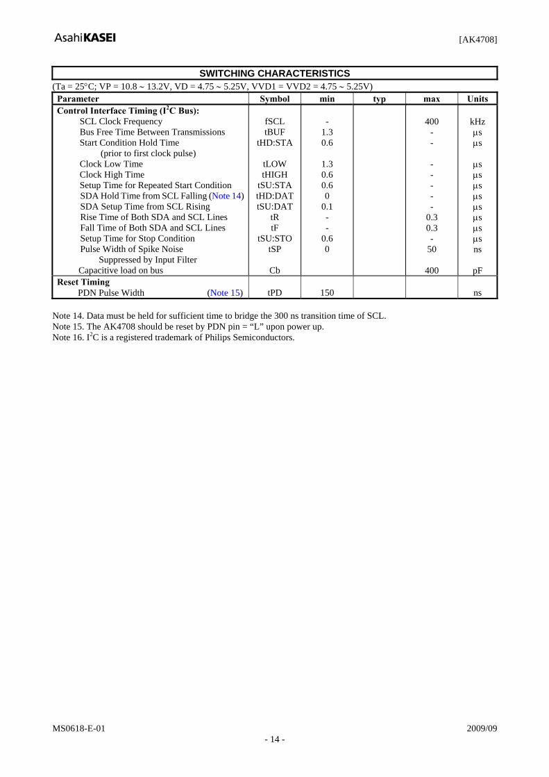
SWITCHING CHARACTERISTICS (Ta = 25°C; VP = 10.8 ∼ 13.2V, VD = 4.75 ∼ 5.25V, VVD1 = VVD2 = 4.75 ∼ 5.25V) Parameter Symbol min typ max Units Control Interface Timing (I2C Bus): SCL Clock Frequency Bus Free Time Between Transmissions Start Condition Hold Time (prior to first clock pulse) Clock Low Time Clock High Time Setup Time for Repeated Start Condition
SDA Hold Time from SCL Falling (Note 14) SDA Setup Time from SCL Rising Rise Time of Both SDA and SCL Lines Fall Time of Both SDA and SCL Lines Setup Time for Stop Condition Pulse Width of Spike Noise Suppressed by Input Filter
Capacitive load on bus
fSCL tBUF
tHD:STA
tLOW tHIGH
tSU:STA tHD:DATtSU:DAT
tR tF
tSU:STO tSP
Cb
-
1.3 0.6
1.3 0.6 0.6 0
0.1 - -
0.6 0
400
- - - - - - -
0.3 0.3 -
50
400
kHz μs μs
μs μs μs μs μs μs μs μs ns
pF Reset Timing PDN Pulse Width (Note 15)
tPD
150
ns
Note 14. Data must be held for sufficient time to bridge the 300 ns transition time of SCL. Note 15. The AK4708 should be reset by PDN pin = “L” upon power up. Note 16. I2C is a registered trademark of Philips Semiconductors.
[AK4708]
MS0618-E-01 2009/09 - 15 -
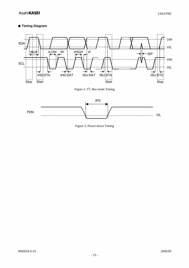
Timing Diagram
tHIGH
SCL
SDA VIH
tLOWtBUF
tHD:STA
tR tF
tHD:DAT tSU:DAT tSU:STA
Stop Start Start Stop
tSU:STO
VIL
VIH
VIL
tSP
Figure 2. I2C Bus mode Timing
tPD
VILPDN
Figure 3. Power-down Timing

[AK4708]
MS0618-E-01 2009/09 - 16 -
OPERATION OVERVIEW 1. System Reset and Power-down options The AK4708 should be reset once by bringing PDN pin = “L” upon power-up. The AK4708 has several operation modes. The PDN pin, AUTO bit, BIAS bit, STBY bit and AMP bit control operation modes as shown in Table 1 and Table 2.
Mode PDN pin AUTO bit STBY bit BIAS bit Mode 0 “L” x x x Full Power-down
1 “H” 1 x x Auto Startup mode (Power-on default)
2 “H” 0 1 1 Standby & Mute 3 “H” 0 1 0 Standby
4 “H” 0 0 1 Mute (AMP power down)
5 “H” 0 0 0 Normal operation (AMP operation)
Table 1. Operation Mode Settings (x: Don’t Care)
Mode Register Control
Audio Bias Level
Video Output
TVFB TVSB
VCRFBO VCRSB
0 Full Power-down NOT available
1 No video input
Power down Hi-Z Hi-Z
Pull -down
(Note 17)
Auto Startup mode (Power-on default) Video input
(Note 18) Active Active (Note 25)
2 Standby & mute Power down
3 Standby Active
4 Mute (AMP power down)
Power down
5 Normal operation (AMP operation)
Available
Active (Note 19)
Hi-Z/ Active
Active Active
Note 17. Internally pulled down by 120kΩ (typ) resistor. Note 18. Video input to TVVIN or VCRVIN. Note 19. TVOUTL/R are muted by Mute bit in the default state. Note 20. VCRC, VCRGO, VCRBO output 0V for termination.
Table 2. Status of each operation modes

[AK4708]
MS0618-E-01 2009/09 - 17 -
System Reset and Full Power-down Mode The AK4708 should be reset once by bringing PDN pin = “L” upon power-up. PDN pin: Power down pin
L: Device power down & reset H: Normal operation.
Auto Startup Mode After when the PDN pin is set to “H”, the AK4708 is in the auto startup mode. In this mode, all blocks except for the video detection circuit are powered down. Once the video detection circuit detects video signal from TVVIN pin or VCRVIN pin, the AK4708 goes to the stand-by mode automatically and sends “H” pulse via INT pin. The sources of TVOUTL/R are fixed to VCRINL/R, the sources of VCROUTL/R are fixed to TVINL/R respectively. The source of DC- restore circuit is VCRVIN pin. To exit the auto startup mode, set the AUTO bit to “0”. AUTO bit (00H D3): Auto startup bit
0: Auto startup disable. (Manual startup) 1: Auto startup enable. (default)
Bias Mode When the BIAS bit = “1”, the bias voltage on the audio output goes to GND level. Bringing BIAS bit to “0” changes this bias voltage smoothly from GND to VP/2 by 2sec (typ.). This removes the huge click noise related the sudden change of bias voltage at power-on. The change of BIAS bit from “1” to “0” also makes smooth transient from VP/2 to GND by 2sec (typ). This removes the huge click noise related the sudden change of bias voltage at power-off. BIAS bit (00H D1): Bias-off bit
0: Normal operation. 1: Set the audio bias to GND. (default)
Standby Mode When the AUTO bit = BIAS bit = “0” and the STBY bit = “1”, the AK4708 is forced into TV-VCR loop through mode. In this mode, the sources of TVOUTL/R pins are fixed to VCRINL/R pins; the sources of VCROUTL/R are fixed to TVINL/R pins respectively. All register values themselves are NOT changed by STBY bit = “1”.
STBY bit (00H D0): Standby bit 0: Normal operation. 1: Standby mode. (default)

[AK4708]
MS0618-E-01 2009/09 - 18 -
Normal Operation Mode To change analog switches, set the AUTO bit, BIAS bit and STBY bit to “0”. The AK4708 is in power-down mode until PDN pin = “H”. The Figure 4 shows an example of the system timing at the power-down and power-up by PDN pin. Typical Operation Sequence (auto setup mode) The Figure 4 shows an example of the system timing at auto startup mode.
Auto startup enable PDN pin
Audio out (DC)
TVVOUT, VCRVOUT
Active (loop-through)
TVVIN Signal in No Signal don’t care Signal in No Signal don’t care
VCRVIN Signal in No Signal don’t care don’t care
Active (loop-through) Hi-Z Hi-Z Active (loop-through)
(GND) Active (loop-through)
No Signal
No Signal
Hi-Z
Low Power Mode Low Power Mode Low Power Mode
AUTO bit “1”(defaoult)
Figure 4.Auto startup mode sequence
Typical Operation Sequence (except auto setup mode) Figure 5 shows an example of the system timing at normal operation mode.
PDN pin
“1” (default) STBY bit “0” “1”
“1” (default) BIAS bit “0”
“Stand-by“
“1” “0”
“Stand-by“ “Mute”
TV out
AMP TV-Source select
VCR in
VCR inVCR in
(Note 21)
VCR in
fixed to VCR in(Loop-through)
(default)
“1” (default)AUTO bit “0”
AMP AMP
fixed to VCR in(Loop-through)
“1”
(Note 22)
Note 21. Set the STBY bit = “0” to pass for 20.2ms after set the VMUTE bit = “0”, to prevent the click noise. Note 22. Mute the analog outputs externally if click noise affects the system.
Figure 5. Typical operating sequence

[AK4708]
MS0618-E-01 2009/09 - 19 -
2. Audio Block Switch Control The AK4708 has switch matrixes designed primarily for SCART routing. Those are controlled via the control register as shown in Table 3 and Table 4 (Please refer to the Block Diagram). (01H: D1-D0)
TV1 TV0 Source of TVOUTL/R 0 0 AMP 0 1 VCRIN (default) 1 0 Mute 1 1 (Reserved)
Table 3. TVOUT Switch Configuration (01H: D5-D4)
VCR1 VCR0 Source of VCROUTL/R 0 0 AMP 0 1 TVIN (default) 1 0 Mute 1 1 Volume#1 output
Table 4. VCROUT Switch Configuration Volume Control #0 (7-Level Volume) The AK4708 has a 7-level volume control (Volume #0) as shown in Table 5. The volume reflects the change of register value immediately.
Figure 6. Volume #0(Volume Gain=0dB:default), Full Differential Stereo Input
(0DH: D5-D3)
VOL2 VOL1 VOL0 Volume #0 Gain Output Level (Typ)
1 1 1 +12dB 2Vrms (with 0.5Vrms differential input) 1 1 0 +9dB - 1 0 1 +6dB 2Vrms (with 1Vrms differential input) 1 0 0 +3dB - 0 1 1 0dB 2Vrms (with 2Vrms differential input) (default) 0 1 0 -3dB - 0 0 1 -6dB 1Vrms (with 2Vrms differential input) 0 0 0 Mute -
Note: Volume #1=0dB Table 5. Volume #0, Full Differential Stereo Input
2Vrms differential input
TVOUTL/R
(VCROUTL/R)
AINL/R+
AINL/R-
Volume Gain 0dB
Volume #0
1Vrms
1Vrms
2Vrms
0.47μ
0.47μ

[AK4708]
MS0618-E-01 2009/09 - 20 -
Figure 7. Volume #0(Volume Gain=0dB:default), Single-ended Input
(0DH: D5-D3)
VOL2 VOL1
VOL0 Volume #0 Gain Output Level (Typ)
1 1 1 +12dB 2Vrms (with 0.5Vrms input) 1 1 0 +9dB - 1 0 1 +6dB 2Vrms (with 1Vrms input) 1 0 0 +3dB - 0 1 1 0dB 1Vrms (with 1Vrms input) (default) 0 1 0 -3dB - 0 0 1 -6dB 0.5Vrms (with 1Vrms input) 0 0 0 Mute -
Note: Volume #1=0dB Table 6. Volume #0, Single-ended Input
Volume Control #1 (Main Volume) The AK4708 has main volume control (Volume #1) as shown in Table 7. (02H: D5-D0)
L5 L4 L3 L2 L1 L0 Gain 1 0 0 0 1 0 +6dB 1 0 0 0 0 1 +4dB 1 0 0 0 0 0 +2dB 0 1 1 1 1 1 0dB (default) … … … … … … … 0 0 0 0 0 1 -60dB 0 0 0 0 0 0 Mute
Note: The output must not exceed 3Vrms. Table 7. Volume #1
When the MOD bit = “1”(default), changing levels don’t have pop noise. MDT1-0 bits select the transition time (Table 8). When the new gain value 1EH(-2dB) is written to gain resistor while the actual (stable) gain is 1FH(0dB), the gain changes to 1EH(-2dB) within the transition time selected by MDT1-0 bits. The AK4708 compares the actual gain to the value of gain register after finishing the transition time, and re-changes the actual gain to new resister value within the transition time if the register value is different from the actual gain when compared. When the MOD bit = “0” then there is no transition time and the gain changes immediately. This change may cause a click noise.
AINL/R+
AINL/R- TVOUTL/R
(VCROUTL/R)
Volume Gain 0dB
Volume #0
1Vrms 1Vrms
0.47μ
0.47μ

[AK4708]
MS0618-E-01 2009/09 - 21 -
Actual Gain
Gain Register
Transition Time (5.3ms to 42.7ms pop free.)
1FH 1EH
1DH
1EH1FH 1DH
WR [Gain=1EH]
WR [Gain=1CH]
WR [Gain=1DH]
1CH
1CH
compare compare compare (to 1EH) (to 1DH) (to 1CH)
Figure 8. Volume Change Operation (MOD bit = “1”)
MDT1 MDT0 Transition Time
0 0 5.3ms 0 1 10.7ms 1 0 21.3ms 1 1 42.7ms (default)
Table 8. Volume Transition Time (typ.)

[AK4708]
MS0618-E-01 2009/09 - 22 -
3. Video Block Video Switch Control The AK4708 has switches for TV and VCR. Each switch can be controlled via registers independently. When AUTO bit = “1” or STBY bit = “1”, these switches setting is ignored and set to fixed configuration (loop-through mode). Please refer the auto startup mode and standby mode.
(04H: D2-D0)
Mode VTV2-0 bit Source of TVVOUT pin
Source of TVRC pin
Source of TVG pin
Source of TVB pin
Shutdown 000 (Hi-Z) (Hi-Z) (Hi-Z) (Hi-Z) Encoder
CVBS+RGB or Encoder YPbPr
001 ENCV pin
(Encoder CVBS or Y)
ENCRC pin (Encoder Red,C
or Pb)
ENCG pin (Encoder Green
or Y)
ENCB pin (Encoder Blue
or Pr)
Encoder Y/C 1 010 ENCV pin (Encoder Y)
ENCRC pin (Encoder C) (Hi-Z) (Hi-Z)
Encoder Y/C 2 011 ENCY pin (Encoder Y)
ENCC pin (Encoder C) (Hi-Z) (Hi-Z)
VCR (default) 100 VCRVIN pin (VCR CVBS
or Y)
VCRRC pin (VCR Red,C
or Pb)
VCRG pin (VCR Green
or Y)
VCRB pin (VCR Blue
or Pr)
TV CVBS 101 TVVIN pin (TV CVBS) (Hi-Z) (Hi-Z) (Hi-Z)
(Reserved) 110 - - - - (Reserved) 111 - - - -
Table 9. TV video output (Note 23)
(04H: D5-D3)
Mode VVCR2-0 bit Source of VCRVOUT pin
Source of VCRC pin
Source of VCRGO pin
Source of VCRBO pin
Shutdown 000 (Hi-Z) (Hi-Z) (Hi-Z) (Hi-Z)
Encoder CVBS or Y/C 1 001 ENCV pin
(Encoder CVBSor Y)
ENCRC pin (Encoder C) (Hi-Z) (Hi-Z)
Encoder CVBS or Y/C 2 010 ENCY pin
(Encoder CVBSor Y)
ENCC pin (Encoder C) (Hi-Z) (Hi-Z)
TV CVBS (default) 011 TVVIN pin (TV CVBS) (Hi-Z) (Hi-Z) (Hi-Z)
VCR 100 VCRVIN pin (VCR CVBS)
VCRRC pin (VCR Red, C)
VCRG pin (VCR Green)
VCRB pin (VCR Blue)
Encoder CVBS /RGB 101 ENCV pin
(Encoder CVBSor Y)
ENCRC pin (Encoder Red,C
or Pb)
ENCG pin (Encoder Green
or Y)
ENCB pin (Encoder Blue
or Pr) (Reserved) 110 - - - - (Reserved) 111 - - - -
Table 10. VCR video output (Note 23)
Note 23. When input the video signal via ENCRC pin or VCRRC pin, set CLAMP1-0 bits respectively.

[AK4708]
MS0618-E-01 2009/09 - 23 -
Video Output Control (05H: D6-D0, 0CH:D2-D0) Each video output can be set to Hi-Z individually via control registers. These settings are ignored when the AUTO bit = “1”.
TVV: TVVOUT output control TVR: TVRCOUT output control TVG: TVGOUT output control TVB: TVBOUT output control VCRV: VCRVOUT output control VCRC: VCRC output control VCRG: VCRGO output control VCRB: VCRBO output control TVFB: TVFB output control VCRFB: VCRFBO output control
0: Hi-Z. (default) 1: Active. RGB/Chroma Bi-directional Control for VCR SCART (05H: D7, D5) The AK4708 supports the bi-directional RGB/Chroma signal on the VCR SCART.
(AK4708)
VCRRCpin
VCRCpin
VCR SCART
75
0.1u
(CIO bit &VCRC bit) #15 pin
Figure 9. VCR Red/Chroma Bi-directional Control
CIO VCRC State of VCRC pin
0 0 Hi-z (default)
0 1 Active 1 0 Connected to GND 1 1 Connected to GND
Table 11 VCR Red/Chroma Bi-directional Control

[AK4708]
MS0618-E-01 2009/09 - 24 -
(AK4708)
VCRGpin
VCRGOpin
VCR SCART
75
0.1u
(CIO bit &VCRG bit) #11 pin
Figure 10. VCR Green Bi-directional Control
CIO VCRG State of VCRGO pin 0 0 Hi-z (default) 0 1 Active 1 0 Connected to GND 1 1 Connected to GND
Table 12 VCR Green Bi-directional Control
(AK4708)
VCRBpin
VCRBOpin
VCR SCART
75
0.1u
(CIO bit &VCRB bit) #7 pin
Figure 11. VCR Blue Bi-directional Control
CIO VCRB State of VCRC pin
0 0 Hi-z (default) 0 1 Active 1 0 Connected to GND 1 1 Connected to GND
Table 13 VCR Blue Bi-directional Control

[AK4708]
MS0618-E-01 2009/09 - 25 -
Clamp and DC-restore circuit control (06H: D7-D2) Each CVBS and Y input has the sync tip clamp circuit. The DC-restore circuit has two clamp voltages 0.7V(typ) and 2.2V(typ) to support both RGB and YPbPr signal. They correspond to 0.35V(typ) and 1.1V(typ) at the SCART connector when matched by 75Ω resistors. The CLAMP1, CLAMP0 and CLAMPB bits select the input circuit for ENCRC pin (Encoder Red/Chroma), ENCB pin (Encoder Blue), VCRRC pin (VCR Red/Chroma) and VCRB pin (VCR Blue) respectively. VCLP2-0 bits select the sync source of DC- restore circuit.
CLAMPB CLAMP0 VCRRC Input Circuit VCRB Input Circuit note
0 0 DC restore clamp active (0.7V at sync timing/output pin)
DC restore clamp active (0.7V at sync timing/output pin) for RGB
0 1 Biased (2.2V at sync timing/output pin)
(DC restore clamp active) (0.7V at sync timing output pin) for Y/C (default)
1 0 DC restore clamp active (2.2V at sync timing/output pin)
DC restore clamp active (2.2V at sync timing/output pin) for Y/Pb/Pr
1 1 (reserved) (reserved) Table 14. DC-restore control for VCR Input
CLAMPB CLAMP1 ENCRC Input Circuit ENCB Input Circuit note
0 0 DC restore clamp active (0.7V at sync timing/output pin)
DC restore clamp active (0.7V at sync timing/output pin) for RGB (default)
0 1 Biased (2.2V at sync timing/output pin)
DC restore clamp active (0.7V at sync timing output pin) for Y/C
1 0 DC restore clamp active (2.2V at sync timing/output pin)
DC restore clamp active (2.2V at sync timing/output pin) for Y/Pb/Pr
1 1 (reserved) (reserved) Table 15. DC-restore control for Encoder Input
CLAMP2 ENCG Input Circuit note
0 DC restore clamp active (0.7V at sync timing/output pin) for RGB (default)
1 Sync tip clamp active (0.7V at sync timing/output pin) for Y/Pb/Pr
Note: When the VTV2-0 bits = “001”(source for TV = Encoder CVBS /RGB), TVG bit = “1” (TVG = active) and VCLP1-0 bits = “11”(DC restore source = ENCG), the sync tip is selected even if the CLAMP2 bit = “0”.
Table 16. DC-restore control for Encoder Green/Y Input
VCLP2-0: DC restore source control
VCLP2 VCLP1 VCLP0 Sync Source of DC Restore 0 0 0 ENCV (default) 0 0 1 ENCY 0 1 0 VCRVIN 0 1 1 ENCG 1 0 0 VCRG 1 0 1 (reserved) 1 1 0 (reserved) 1 1 1 (reserved)
Note: When the AUTO bit = “1”, the source is fixed to VCRVIN. Table 17. DC-restore source control

[AK4708]
MS0618-E-01 2009/09 - 26 -
4. Blanking Control The AK4708 supports Fast Blanking signals and Slow Blanking (Function Switching) signals for TV/VCR SCART. Input/Output Control for Fast/Slow Blanking
FB1-0: TV Fast Blanking output control (07H: D1-D0)
FB1 bit FB0 bit TVFB pin Output Level 0 0 0V (default) 0 1 2V<, 4V(typ) at 150Ω load 1 0 Same as VCR FB input (4V/0V) 1 1 (Reserved)
Table 18. TV Fast Blanking output (Note: minimum load is 150Ω)
SBT1-0: TV Slow Blanking output control (07H: D3-D2)
SBT1 bit SBT0 bit TVSB pin Output Level 0 0 < 2V (default) 0 1 5V <, < 7V 1 0 (Reserved) 1 1 10V <
Table 19. TV Slow Blanking output (Note: minimum load is 10kΩ) FBV: VCR Fast Blanking output control (0CH: D7)
FBV bit VCRFBO pin Output Level
0 0V (default) 1 2V<, 4V(typ) at 150Ω load
Table 20. VCR Fast Blanking output (Note: minimum load is 150Ω)
SBV1-0: VCR Slow Blanking output control (07H: D5-D4)
SBV1 bit SBV0 bit VCRSB pin Output Level 0 0 < 2V (default) 0 1 5V <, < 7V 1 0 (Reserved) 1 1 10V <
Table 21. VCR Slow Blanking output (Note: minimum load is 10kΩ)
SBIO1-0: TV/VCR Slow Blanking I/O control (07H: D7-D6)
SBIO1 bit SBIO0 bit VCRSB pin Direction TVSB pin Direction
0 0 Output (Controlled by SBV1-0 bits)
Output (Controlled by SBT1-0 bits)
(default)
0 1 (Reserved) (Reserved)
1 0 Input (Stored in SVCR1-0 bits)
Output (Controlled by SBT1-0 bits)
1 1 Input (Stored in SVCR1-0 bits)
Output (Same output as VCR SB)
Table 22. TV/VCR Slow Blanking I/O control

[AK4708]
MS0618-E-01 2009/09 - 27 -
VCR Fast Blanking for VCR SCART (0CH: D7, D2) The AK4708 supports the bi-directional VCR Fast Blanking signal on the VCR SCART.
(AK4708)
VCRFBpin
VCRFBOpin
VCR SCART
75
(VCRFB bit) #16 pin
6dB
0V
2V
(FBV bit)
Figure 12. VCR Fast Blanking Bi-directional Control
FBV VCRFB State of VCRFBO pin 0 0 Hi-Z (default) 0 1 Active / 0V(typ) 1 0 Hi-Z 1 1 Active / 2V<, 4V(typ) at 150Ω load
Table 23 VCR Fast Blanking Bi-directional Control

[AK4708]
MS0618-E-01 2009/09 - 28 -
5. Monitor Options and INT function Monitor Options (08H: D4-D0) The AK4708 has several detection functions. SVCR1-0 bits, FVCR bit, VCMON bit and TVMON bit reflect the input DC level of VCR slow blanking, the input DC level of VCR fast blanking and signals input to TVVIN or VCRVIN pins.
SVCR1-0: VCR Slow blanking status monitor SVCR1-0 bits reflect the voltage at VCRSB pin only when the VCRSB is in the input mode. When the VCRSB is in the output mode, SVCR1-0 bits hold previous value.
VCRSB pin input level SVCR1 bit SVCR0 bit < 2V 0 0
4.5 to 7V 0 1 (Reserved) 1 0
9.5 < 1 1 Table 24. VCR Slow Blanking monitor
FVCR: VCR Fast blanking input level monitor
This bit is enabled when TVFB bit = “1”.
VCRFB pin input level FVCR bit < 0.4V 0 1V < 1
Table 25. VCR Fast Blanking monitor (Typical threshold is 0.7V)
VCMON: VCRVIN pin video input monitor (MCOMN bit = “1”), TVVIN pin or VCRVIN pin video input monitor (MCOMN bit = “0”) 0: No video signal detected.
1: Detects video signal. TVMON: TVVIN pin video input monitor (active when MCOMN bit = “1”)
0: No video signal detected. 1: Detects video signal.
AUTO
(00H D3) MCOMN (09H D7) TVVIN signal VCRVIN signal TVMON
(08H D4) VCMON (08H D3)
0 0 0 0 0 0 0 0 0 1 0 1 0 0 1 0 0 1 0 0 1 1 0 1 0 1 0 0 0 0 0 1 0 1 0 1 0 1 1 0 1 0 0 1 1 1 1 1 1 x 0 0 0 0 1 x 0 1 0 1 1 x 1 0 0 1 1 x 1 1 0 1
(x: don’t care) Note 24. TVVIN/VCRVIN signal: signal 0 = No signal applied, signal 1 = signal applied
Table 26. TV/VCR Monitor Function

[AK4708]
MS0618-E-01 2009/09 - 29 -
INT Function and Mask Options (09H: D3-D1) Changes of the 08H status can be monitored via the INT pin. The INT pin is the open drain output and goes “L” for 2μs (typ.) when the status of 08H is changed. This pin should be connected to VD (typ. 5V) through 10kΩ resistor or lower voltage through 10kΩ resistor. MTV bit, MVC bit, MCOMN bit, MFVCR bit and MSVCR bit control the reflection of the status change of these monitors onto the INT pin from report to prevent to masks each monitor.
AK4708
R=10kΩ
INT
5V
uP
Figure 13. INT pin
MVC: VCMON Mask. Refer Table 28. MTV: TVMON Mask. Refer Table 27. MCOMN: Refer Table 26
AUTO (00H D3)
TVMON (08H D4)
MTV (09H D4) INT
0 No Change 0 Hi-Z 0 No Change 1 Hi-Z 0 Change 0 Generates “L” Pulse 0 Change 1 Hi-Z 1 No Change 0 Hi-Z 1 No Change 1 Hi-Z
Note 25. When the STBY bit = “0”, the TV Monitor Mask function is enabled. Note 26. When AUTO bit = “1”, TVMON does not change
Table 27. TV Monitor Mask
AUTO (00H D3)
VCMON (08H D3)
MVC (09H D3) INT
0 No Change 0 Hi-Z 0 No Change 1 Hi-Z 0 Change 0 Generates “L” Pulse 0 Change 1 Hi-Z 1 No Change 0 Hi-Z 1 No Change 1 Hi-Z 1 Change 0 Generates “L” Pulse 1 Change 1 Generates “L” Pulse
Note 27. When the STBY bit = “0”, the VCR Monitor Mask function is enabled. Table 28. VCR Monitor Mask
MFVCR: FVCR Monitor mask.
0: Change of FVCR is reflected to INT pin. (default) 1: Change of FVCR is NOT reflected to INT pin. MSVCR: SVCR1-0 Monitor mask
0: Change of SVCR1-0 is reflected to INT pin. (default) 1: Change of SVCR1-0 is NOT reflected to INT pin.

[AK4708]
MS0618-E-01 2009/09 - 30 -
6. Control Interface I2C-bus Control Mode 1. WRITE Operations Figure 14 shows the data transfer sequence in I2C-bus mode. All commands are preceded by a START condition. A HIGH to LOW transition on the SDA line while SCL is HIGH indicates a START condition (Figure 20). After the START condition, a slave address is sent. This address is 7bits long followed by the eighth bit that is a data direction bit (R/W). The most significant seven bits of the slave address are fixed as “0010001”. If the slave address match that of the AK4708, the AK4708 generates the acknowledge and the operation is executed. The master must generate the acknowledge-related clock pulse and release the SDA line (HIGH) during the acknowledge clock pulse (Figure 22). A “1” for R/W bit indicates that the read operation is to be executed. A “0” indicates that the write operation is to be executed. The second byte consists of the address for control registers of the AK4708. The format is MSB first, and those most significant 3-bits are fixed to zeros (Figure 16). The data after the second byte contain control data. The format is MSB first, 8bits (Figure 17). The AK4708 generates an acknowledge after each byte has been received. A data transfer is always terminated by a STOP condition generated by the master. A LOW to HIGH transition on the SDA line while SCL is HIGH defines a STOP condition (Figure 20). The AK4708 can execute multiple one byte write operations in a sequence. After receipt of the third byte, the AK4708 generates an acknowledge, and awaits the next data again. The master can transmit more than one byte instead of terminating the write cycle after the first data byte is transferred. After the receipt of each data, the internal address counter is incremented by one, and the next data is taken into next address automatically. If the address exceeds 0DH prior to generating the stop condition, the address counter will “roll over” to 00H and the previous data will be overwritten. The data on the SDA line must be stable during the HIGH period of the clock. The HIGH or LOW state of the data line can only change when the clock signal on the SCL line is LOW (Figure 22) except for the START and the STOP condition.
SDA
START
ACK
ACK
S SlaveAddress
ACK
SubAddress(n) Data(n) P
STOP
Data(n+x)
ACK
Data(n+1)
ACK
R/W= “0”
ACK
Figure 14. Data transfer sequence at the I2C-bus mode
0 0 1 0 0 0 1 R/W
Figure 15. The first byte
0 0 0 A4 A3 A2 A1 A0
Figure 16. The second byte
D7 D6 D5 D4 D3 D2 D1 D0
Figure 17. Byte structure after the second byte

[AK4708]
MS0618-E-01 2009/09 - 31 -
2. READ Operations Set R/W bit = “1” for READ operations. After transmission of data, the master can read the next address’s data by generating an acknowledge instead of terminating the write cycle after the receipt the first data word. After the receipt of each data, the internal address counter is incremented by one, and the next data is taken into next address automatically. If the address exceeds 09H prior to generating the stop condition, the address counter will “roll over” to 00H and the previous data will be overwritten. The AK4708 supports two basic read operations: CURRENT ADDRESS READ and RANDOM READ. 2-1. CURRENT ADDRESS READ The AK4708 contains an internal address counter that maintains the address of the last word accessed, incremented by one. Therefore, if the last access (either a read or write) was to address n, the next CURRENT READ operation would access data from the address n+1. After receipt of the slave address with R/W bit set to “1”, the AK4708 generates an acknowledge, transmits 1byte data which address is set by the internal address counter and increments the internal address counter by 1. If the master does not generate an acknowledge to the data but generate the stop condition, the AK4708 discontinues transmission.
SDA
START
ACK
ACK
S SlaveAddress
ACK
Data(n+1) P
STOP
Data(n+x)
ACK
Data(n+2)
ACK
R/W= “1”
ACK
Data(n)
Figure 18. CURRENT ADDRESS READ
2-2. RANDOM READ Random read operation allows the master to access any memory location at random. Prior to issuing the slave address with the R/W bit set to “1”, the master must first perform a “dummy” write operation. The master issues a start condition, slave address (R/W bit = “0”) and then the register address to read. After the register address is acknowledge, the master immediately reissues the start condition and the slave address with the R/W bit set to “1”. Then the AK4708 generates an acknowledge, 1-byte data and increments the internal address counter by 1. If the master does not generate an acknowledge to the data but generate the stop condition, the AK4708 discontinues transmission.
SDA
START
ACK
ACK
S SlaveAddress
ACK
Data(n) P
STOP
Data(n+x)
ACK
Data(n+1)
ACK
R/W= “0”
ACK
SubAddress(n)
START
ACK
S SlaveAddress
R/W= “1”
Figure 19. RANDOM ADDRESS READ

[AK4708]
MS0618-E-01 2009/09 - 32 -
SCL
SDA
stop conditionstart condition
S P
Figure 20. START and STOP conditions
SCL FROMMASTER
acknowledge
DATAOUTPUT BYTRANSMITTER
DATAOUTPUT BYRECEIVER
1 98
STARTCONDITION
not acknowledge
clock pulse foracknowledgement
S
2
Figure 21. Acknowledge on the I2C-bus
SCL
SDA
data linestable;
data valid
changeof dataallowed
Figure 22. Bit transfer on the I2C-bus
[AK4708]
MS0618-E-01 2009/09 - 33 -
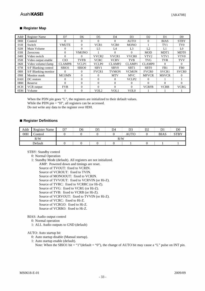
Register Map
Addr Register Name D7 D6 D5 D4 D3 D2 D1 D0 00H Control 0 0 0 0 AUTO 0 BIAS STBY 01H Switch VMUTE 0 VCR1 VCR0 MONO 1 TV1 TV0 02H Main Volume 0 0 L5 L4 L3 L2 L1 L0 03H Zerocross 0 VMONO 1 0 0 MOD MDT1 MDT0 04H Video switch 0 0 VVCR2 VVCR1 VVCR0 VTV2 VTV1 VTV0 05H Video output enable CIO TVFB VCRC VCRV TVB TVG TVR TVV 06H Video volume/clamp CLAMPB VCLP1 VCLP0 CLAMP2 CLAMP1 CLAMP0 0 0 07H S/F Blanking control SBIO1 SBIO0 SBV1 SBV0 SBT1 SBT0 FB1 FB0 08H S/F Blanking monitor 0 0 FVCR1 TVMON VCMON FVCR0 SVCR1 SVCR0 09H Monitor mask MCOMN 0 0 MTV MVC MFVCR MSVCR 0 0AH DC restore 0 0 0 0 VCLP2 0 1 1 0BH Reserve 0 0 0 0 0 0 0 0 0CH VCR output FVB 0 0 0 0 VCRFB VCRB VCRG 0DH Volume 0 0 VOL2 VOL1 VOL0 1 1 1
When the PDN pin goes “L”, the registers are initialized to their default values. While the PDN pin = “H”, all registers can be accessed. Do not write any data to the register over 0DH.
Register Definitions
Addr Register Name D7 D6 D5 D4 D3 D2 D1 D0 00H Control 0 0 0 0 AUTO 0 BIAS STBY
R/W R/W Default 0 0 0 0 1 0 1 1
STBY: Standby control
0: Normal Operation 1: Standby Mode (default). All registers are not initialized.
AMP: Powered down and timings are reset. Source of TVOUT: fixed to VCRIN. Source of VCROUT: fixed to TVIN. Source of MONOOUT: fixed to VCRIN. Source of TVVOUT: fixed to VCRVIN (or Hi-Z). Source of TVRC: fixed to VCRRC (or Hi-Z). Source of TVG: fixed to VCRG (or Hi-Z). Source of TVB: fixed to VCRB (or Hi-Z). Source of VCRVOUT: fixed to TVVIN (or Hi-Z). Source of VCRC: fixed to Hi-Z. Source of VCRGO: fixed to Hi-Z. Source of VCRBO: fixed to Hi-Z.
BIAS: Audio output control
0: Normal operation 1: ALL Audio outputs to GND (default)
AUTO: Auto startup bit
0: Auto startup disable (Manual startup). 1: Auto startup enable (default).
Note: When the SBIO1 bit = “1”(default = “0”), the change of AUTO bit may cause a “L” pulse on INT pin.

[AK4708]
MS0618-E-01 2009/09 - 34 -
Addr Register Name D7 D6 D5 D4 D3 D2 D1 D0 01H Switch VMUTE 0 VCR1 VCR0 MONO 1 TV1 TV0
R/W R/W Default 1 0 0 1 0 1 0 1
TV1-0: TVOUTL/R pins source switch
00: AMP 01: VCRINL/R pins (default) 10: MUTE 11: Reserved
MONO: Mono select for TVOUTL/R pins
0: Stereo. (default) 1: Mono. (L+R)/2
VCR1-0: VCROUTL/R pins source switch
00: AMP 01: TVINL/R pins (default) 10: MUTE 11: Volume#1 output
VMUTE: Mute switch for volume #1
0: Normal operation 1: Mute the volume #1 (default)
Addr Register Name D7 D6 D5 D4 D3 D2 D1 D0
02H Main volume 0 0 L5 L4 L3 L2 L1 L0 R/W R/W
Default 0 0 0 1 1 1 1 1
L5-0: Volume #1 control Those registers control both Lch and Rch of Volume #1.
111111 to 100011: (Reserved)
100010: Volume gain = +6dB 100001: Volume gain = +4dB 100000: Volume gain = +2dB 011111: Volume gain = +0dB (default) 011110: Volume gain = -2dB ...
000011: Volume gain = -56dB 000010: Volume gain = -58dB
000001: Volume gain = -60dB 000000: Volume gain = Mute

[AK4708]
MS0618-E-01 2009/09 - 35 -
Addr Register Name D7 D6 D5 D4 D3 D2 D1 D0 03H Volume Control 0 VMONO 1 0 0 MOD MDT1 MDT0
R/W R/W Default 0 0 1 0 0 1 1 1
MDT1-0: The time length control of volume transition time 00: typ. 5.3 ms 01: typ. 10.7 ms 10: typ. 21.3 ms 11: typ. 42.7 ms (default) MOD: Soft transition enable for volume #1 control 0: Disable The volume value changes immediately without soft transition. 1: Enable (default) The volume value changes with soft transition. This function is disabled when STBY bit = “1”.
VMONO: Mono select for VCROUTL/R pins
0: Stereo. (default) 1: Mono. (L+R)/2

[AK4708]
MS0618-E-01 2009/09 - 36 -
Addr Register Name D7 D6 D5 D4 D3 D2 D1 D0 04H Video switch 0 0 VVCR2 VVCR1 VVCR0 VTV2 VTV1 VTV0
R/W R/W Default 0 0 0 1 1 1 0 0
VTV2-0: Selector for TV video output
Refer Table 9.
VVCR2-0: Selector for VCR video output Refer Table 10.
Addr Register Name D7 D6 D5 D4 D3 D2 D1 D0 05H Output Enable CIO TVFB VCRC VCRV TVB TVG TVR TVV
R/W R/W Default 0 0 0 0 0 0 0 0
TVV: TVVOUT output control TVR: TVRCOUT output control TVG: TVGOUT output control TVB: TVBOUT output control VCRV: VCRVOUT output control VCRC: VCRC output control TVFB: TVFB output control
0: Hi-Z (default) 1: Active.
CIO: VCR RGB I/O control for VCR SCART
Refer Table 11, Table 12 and Table 13.

[AK4708]
MS0618-E-01 2009/09 - 37 -
Addr Register Name D7 D6 D5 D4 D3 D2 D1 D0
06H Video volume CLAMPB VCLP1 VCLP0 CLAMP2 CLAMP1 CLAMP0 0 0
R/W R/W Default 0 0 0 0 0 1 0 0
CLAMPB, CLAMP2-0: Clamp control. Refer Table 14, Table 15 and Table 16.
VCLP1-0: DC restore source control
00: ENCV pin (default) 01: ENCY pin 10: VCRVIN pin 11: (Reserved)
When the AUTO bit = “1”, the source is fixed to VCRVIN pin.
Addr Register Name D7 D6 D5 D4 D3 D2 D1 D0 07H S/F Blanking SBIO1 SBIO0 SBV1 SBV0 SBT1 SBT0 FB1 FB0
R/W R/W Default 0 0 0 0 0 0 0 0
FB1-0: TV Fast Blanking output control (for TVFB pin)
00: 0V (default) 01: 2V<, 4V(typ) at 150Ω load 10: follow VCR FB input (4V/0V) 11: (Reserved)
SBT1-0: TV Slow Blanking output control (for TVSB pin. minimum load is 10kΩ.)
00: < 2V (default) 01: 5V <, < 7V 10: (Reserved) 11: 10V <
SBV1-0: VCR Slow Blanking output control (for VCRSB pin. minimum load is 10kΩ.)
00: < 2V (default) 01: 5V <, < 7V 10: (Reserved) 11: 10V <
SBIO1-0: TV/VCR Slow Blanking I/O control
Refer Table 22.
Addr Register Name D7 D6 D5 D4 D3 D2 D1 D0
08H Monitor 0 0 FVCR1 TVMON VCMON FVCR0 SVCR1 SVCR0R/W READ
Default 0 0 0 0 0 0 0 0
SVCR1-0, FVCR1-0: VCR fast blanking/slow blanking monitor Refer Table 24, Table 25. VCMON, TVMON: VCR/TV video input monitor
Refer Table 26.

[AK4708]
MS0618-E-01 2009/09 - 38 -
Addr Register Name D7 D6 D5 D4 D3 D2 D1 D0 09H Monitor mask MCOMN 0 0 MTV MVC MFVCR MSVCR 0
R/W R/W Default 0 0 0 0 1 0 0 0
MSVCR: SVCR1-0 bits Monitor mask
0: The INT pin reflects the change of SVCR1-0 bit. (default) 1: The INT pin does not reflect the change of SVCR1-0 bits.
MFVCR: FVCR Monitor mask
0: The INT pin reflects the change of MFVCR bit. (default) 1: The INT pin does not reflect the change of MFVCR bit.
MVC: VCR input monitor mask
Refer Table 28.
MTV: TV input monitor mask Refer Table 27.
MCOMN: Monitor mask option
Refer Table 26.
Addr Register Name D7 D6 D5 D4 D3 D2 D1 D0
0AH DC restore 0 0 0 0 VCLP2 0 1 1 R/W R/W
Default 0 0 0 0 0 0 1 1 VCLP2: DC restore source control
Refer Table 17
Addr Register Name D7 D6 D5 D4 D3 D2 D1 D0 0CH VCR output FBV 0 0 0 0 VCRFB VCRB VCRG
R/W R/W Default 0 0 0 0 0 0 0 0
VCRG: VCRGO output control VCRB: VCRBO output control VCRFB: VCRFBO output control
0: Hi-Z (default) 1: Active.
FBV: VCR Fast Blanking output control (for VCRFBO pin)
0: 0V (default) 0: 2V<, 4V(typ) at 150Ω load

[AK4708]
MS0618-E-01 2009/09 - 39 -
Addr Register Name D7 D6 D5 D4 D3 D2 D1 D0
0DH Main volume 0 0 VOL2 VOL1 VOL0 1 1 1 R/W R/W
Default 0 0 0 1 1 1 1 1
VOL2-0: Volume #0 control Those registers control both Lch and Rch of Volume #0.
111: Volume gain = +12dB 110: Volume gain = +9dB 101: Volume gain = +6dB 100: Volume gain = +3dB 011: Volume gain = +0dB (default)
010: Volume gain = -3dB 001: Volume gain = -6dB
000: MUTE

[AK4708]
MS0618-E-01 2009/09 - 40 -
SYSTEM DESIGN Figure 23 shows the system connection diagram example. The evaluation board AKD4708 demonstrates application circuits, the optimum layout, power supply arrangements and measurement results.
TVFB
1
VVD1
2 VVSS
3 TVVOUT
4 VVD2
5 TVRC
6
7
TVG
8
TVB
9 ENCB
10 ENCG
11
VC
RV
OU
T
PD
N
SD
A
SC
L
AIN
L+
AIN
L-
AIN
R+
AIN
R-
13
14
15
16
17
18
19
20
21
22
23
AK4708EQ
ENCRC
12
EN
CV
EN
CY
TVVI
N
VC
RV
IN
VC
RFB
VC
RR
C
VC
RG
VC
RB
INT
VC
RS
B
TVSB
V
CR
INR
24
35
34
33
32
31
30
29
28
27
26
25
36
DVCOM
VP
VCROUTL
VCROUTR
TVINL
TVOUTL
TVOUTR
TVINRVCRINL
PVCOM48 47 46 45 44 43 42 41 40 39 38 37
ENCC
75
75
75
Video 5V 0.1u
0.1u
0.1u
0.1u
VID
EO
enco
der 0.
1u
75
10u 0.1u
+ +
MP
EG
M
icro
cont
rolle
r
10u 0.1u Audio 5V
0.47
u
0.47
u
0.47
u
0.47
u
deco
der
DA
CL
DA
CR
75
75
+
+
Analog 12V
+
10u+ 10u 220k
+ 10u+ 10u
TV S
CA
RT
220k
220k 220k
300
300
300
300
0.47u 300
0.47u 300
0.47u 300
0.1u
0.1u
0.1u
0.1u
0.1u
0.1u
VC
R S
CA
RT
300
0.47
u 40
0 40
0
75
75
75
75
10u
10u 0.1u
75
75
75
75
Analog GroundDigital Ground
+
VSS
VD10u
10u 0.1u
0.1u
0.1u
VCRC 75
75
75
75
VC
RFB
O
VC
RG
O
VC
RB
O
+
Figure 23. Typical Connection Diagram

[AK4708]
MS0618-E-01 2009/09 - 41 -
Grounding and Power Supply Decoupling VD, VP, VVD1, VVD2, VSS and VVSS should be supplied from analog supply unit with low impedance and be separated from system digital supply. An electrolytic capacitor 10μF parallel with a 0.1μF ceramic capacitor should be attached to these pins to eliminate the effects of high frequency noise. The 0.1μF ceramic capacitor should be placed as near to VD (VP, VVD1, VVD2) as possible. Voltage Reference Each DVCOM/PVCOM are common voltage of this chip. An electrolytic capacitor 10μF parallel with a 0.1μF ceramic capacitor should be attached to these VCOM pins to eliminate the effects of high frequency noise. No load current should be drawn from these VCOM pins. All signals, especially clocks, should be kept away from these VCOM pins in order to avoid unwanted coupling into the AK4708. Analog Audio Outputs The analog outputs are also single-ended and centered on 5.6V(typ.). The output signal range is typically 2Vrms .

[AK4708]
MS0618-E-01 2009/09 - 42 -
External Circuit Example
Analog Audio Input pin
TVINL/R VCRINL/R 0.47μF
300Ω
(Cable)
Analog Audio Input pin
AINR+ AINR- AINL+ AINL-
0.47μF
Analog Audio Output pin
TVOUTL/R VCROUTL/R
10μF 300Ω
Total > 4.5kΩ
(Cable)
Analog Video Input pin
ENCV, ENCY, VCRVIN, TVVIN, ENCRC, ENCC, VCRRC, ENCG, VCRG, ENCB, VCRB
0.1μF
75Ω
(Cable) 75Ω
Analog Video Output pin
TVVOUT, TVRC TVG, TVR, TVB, VCRVOUT,VCRC, VCRBO,VCRGO
max 400pF
75Ω
75Ω max 15pF
(Cable)

[AK4708]
MS0618-E-01 2009/09 - 43 -
Slow Blanking pin
TVSB VCRSB
max 3nF (with 400Ω)
400Ω (max 500Ω)
min: 10kΩ
(Cable)
Fast Blanking Input pin
VCRFB
75Ω
(Cable) 75Ω
Fast Blanking Output pin
TVFB, VCRFBO
75Ω
75Ω
(Cable)

[AK4708]
MS0618-E-01 2009/09 - 44 -
PACKAGE
1 12
48 13
7.0
9.0 ± 0.2
7.0
9.0
± 0.
2
0.22 ± 0.08
48pin LQFP (Unit: mm)
0.10
37 24
25 36
0.09 ∼ 0.20
1.40 ± 0.05
0.13 ± 0.13
1.70Max
0° ∼ 10°
0.10 M
0.3 ∼ 0.75
0.5
Package & Lead frame material Package molding compound: Epoxy Lead frame material: Cu Lead frame surface treatment: Solder (Pb free) plate

[AK4708]
MS0618-E-01 2009/09 - 45 -
MARKING
AK4708EQ XXXXXXX
1
XXXXXXXX: Date code identifier
REVISION HISTORY
Date (YY/MM/DD) Revision Reason Page Contents 07/04/25 00 First Edition
09/09/16 01 Specification Change
44 PACKAGE Package dimensions were changed.

[AK4708]
MS0618-E-01 2009/09 - 46 -
IMPORTANT NOTICE
These products and their specifications are subject to change without notice. When you consider any use or application of these products, please make inquiries the sales office of Asahi Kasei Microdevices Corporation (AKM) or authorized distributors as to current status of the products.
AKM assumes no liability for infringement of any patent, intellectual property, or other rights in the application or use of any information contained herein.
Any export of these products, or devices or systems containing them, may require an export license or other official approval under the law and regulations of the country of export pertaining to customs and tariffs, currency exchange, or strategic materials.
AKM products are neither intended nor authorized for use as critical componentsNote1) in any safety, life support, or other hazard related device or systemNote2), and AKM assumes no responsibility for such use, except for the use approved with the express written consent by Representative Director of AKM. As used here:
Note1) A critical component is one whose failure to function or perform may reasonably be expected to result, whether directly or indirectly, in the loss of the safety or effectiveness of the device or system containing it, and which must therefore meet very high standards of performance and reliability. Note2) A hazard related device or system is one designed or intended for life support or maintenance of safety or for applications in medicine, aerospace, nuclear energy, or other fields, in which its failure to function or perform may reasonably be expected to result in loss of life or in significant injury or damage to person or property.
It is the responsibility of the buyer or distributor of AKM products, who distributes, disposes of, or otherwise places the product with a third party, to notify such third party in advance of the above content and conditions, and the buyer or distributor agrees to assume any and all responsibility and liability for and hold AKM harmless from any and all claims arising from the use of said product in the absence of such notification.