Embed Size (px)
Citation preview
Avaya Call Management SystemSun Netra 210 ComputerHardware Installation, Maintenance, and Troubleshooting
May 2009
© 2009 Avaya Inc. All Rights Reserved.
NoticeWhile reasonable efforts were made to ensure that the information in this document was complete and accurate at the time of printing, Avaya Inc. can assume no liability for any errors. Changes and corrections to the information in this document might be incorporated in future releases.
Documentation disclaimerAvaya Inc. is not responsible for any modifications, additions, or deletions to the original published version of this documentation unless such modifications, additions, or deletions were performed by Avaya. Customer and/or End User agree to indemnify and hold harmless Avaya, Avaya's agents, servants and employees against all claims, lawsuits, demands and judgments arising out of, or in connection with, subsequent modifications, additions or deletions to this documentation to the extent made by the Customer or End User.
Link disclaimerAvaya Inc. is not responsible for the contents or reliability of any linked Web sites referenced elsewhere within this documentation, and Avaya does not necessarily endorse the products, services, or information described or offered within them. We cannot guarantee that these links will work all the time and we have no control over the availability of the linked pages.
WarrantyAvaya Inc. provides a limited warranty on this product. Refer to your sales agreement to establish the terms of the limited warranty. In addition, Avaya’s standard warranty language, as well as information regarding support for this product, while under warranty, is available through the Avaya Support Web site:http://www.avaya.com/support
LicenseUSE OR INSTALLATION OF THE PRODUCT INDICATES THE END USER'S ACCEPTANCE OF THE TERMS SET FORTH HEREIN AND THE GENERAL LICENSE TERMS AVAILABLE ON THE AVAYA WEB SITE http://support.avaya.com/LicenseInfo/ ("GENERAL LICENSE TERMS"). IF YOU DO NOT WISH TO BE BOUND BY THESE TERMS, YOU MUST RETURN THE PRODUCT(S) TO THE POINT OF PURCHASE WITHIN TEN (10) DAYS OF DELIVERY FOR A REFUND OR CREDIT.Avaya grants End User a license within the scope of the license types described below. The applicable number of licenses and units of capacity for which the license is granted will be one (1), unless a different number of licenses or units of capacity is specified in the Documentation or other materials available to End User. "Designated Processor" means a single stand-alone computing device. "Server" means a Designated Processor that hosts a software application to be accessed by multiple users. "Software" means the computer programs in object code, originally licensed by Avaya and ultimately utilized by End User, whether as stand-alone Products or pre-installed on Hardware. "Hardware" means the standard hardware Products, originally sold by Avaya and ultimately utilized by End User.
License type(s)Designated System(s) License (DS). End User may install and use each copy of the Software on only one Designated Processor, unless a different number of Designated Processors is indicated in the Documentation or other materials available to End User. Avaya may require the Designated Processor(s) to be identified by type, serial number, feature key, location or other specific designation, or to be provided by End User to Avaya through electronic means established by Avaya specifically for this purpose.Concurrent User License (CU). End User may install and use the Software on multiple Designated Processors or one or more Servers, so long as only the licensed number of Units are accessing and using the Software at any given time. A "Unit" means the unit on which Avaya, at its sole discretion, bases the pricing of its licenses and can be, without limitation, an agent, port or user, an e-mail or voice mail account in the name of a person or corporate function (e.g., webmaster or helpdesk), or a directory entry in the administrative database utilized by the Product that permits one user to interface with the Software. Units may be linked to a specific, identified Server.
Copyright Except where expressly stated otherwise, the Product is protected by copyright and other laws respecting proprietary rights. Unauthorized reproduction, transfer, and or use can be a criminal, as well as a civil, offense under the applicable law.
Third-party componentsCertain software programs or portions thereof included in the Product may contain software distributed under third party agreements ("Third Party Components"), which may contain terms that expand or limit rights to use certain portions of the Product ("Third Party Terms"). Information identifying Third Party Components and the Third Party Terms that apply to them is available on the Avaya Support Web site:http://support.avaya.com/ThirdPartyLicense/
Preventing toll fraud"Toll fraud" is the unauthorized use of your telecommunications system by an unauthorized party (for example, a person who is not a corporate employee, agent, subcontractor, or is not working on your company's behalf). Be aware that there can be a risk of toll fraud associated with your system and that, if toll fraud occurs, it can result in substantial additional charges for your telecommunications services.
Avaya fraud interventionIf you suspect that you are being victimized by toll fraud and you need technical assistance or support, call Technical Service Center Toll Fraud Intervention Hotline at +1-800-643-2353 for the United States and Canada. For additional support telephone numbers, see the Avaya Support Web site:http://www.avaya.com/support
TrademarksAvaya and the Avaya logo are either registered trademarks or trademarks of Avaya Inc. in the United States of America and/or other jurisdictions.All other trademarks are the property of their respective owners.
Downloading documentsFor the most current versions of documentation, see the Avaya Support Web site:http://www.avaya.com/support
Avaya supportAvaya provides a telephone number for you to use to report problems or to ask questions about your product. The support telephone number is 1-800-242-2121 in the United States. For additional support telephone numbers, see the Avaya Support Web site:http://www.avaya.com/support
Avaya CMS Sun Netra 210 Installation, Maintenance, and Troubleshooting May 2009 3
Preface . . . . . . . . . . . . . . . . . . . . . . . . . . . . . . . . . . . . . . . . . . . 7Purpose. . . . . . . . . . . . . . . . . . . . . . . . . . . . . . . . . . . . . . . . . . . . 7Intended users . . . . . . . . . . . . . . . . . . . . . . . . . . . . . . . . . . . . . . . . 8Overview . . . . . . . . . . . . . . . . . . . . . . . . . . . . . . . . . . . . . . . . . . . 8Conventions and terminology . . . . . . . . . . . . . . . . . . . . . . . . . . . . . . . 9Reasons for reissue . . . . . . . . . . . . . . . . . . . . . . . . . . . . . . . . . . . . . 9Documentation Web sites . . . . . . . . . . . . . . . . . . . . . . . . . . . . . . . . . . 9Support . . . . . . . . . . . . . . . . . . . . . . . . . . . . . . . . . . . . . . . . . . . . 10
Installation . . . . . . . . . . . . . . . . . . . . . . . . . . . . . . . . . . . . . . . . . . . 11Preparing for installation . . . . . . . . . . . . . . . . . . . . . . . . . . . . . . . . . . 12
Safety precautions. . . . . . . . . . . . . . . . . . . . . . . . . . . . . . . . . . . . 12System precautions . . . . . . . . . . . . . . . . . . . . . . . . . . . . . . . . . . . 13Required tools . . . . . . . . . . . . . . . . . . . . . . . . . . . . . . . . . . . . . . 14Electrical specifications . . . . . . . . . . . . . . . . . . . . . . . . . . . . . . . . . 14Physical specifications . . . . . . . . . . . . . . . . . . . . . . . . . . . . . . . . . 14Environmental specifications . . . . . . . . . . . . . . . . . . . . . . . . . . . . . . 15Noise specifications . . . . . . . . . . . . . . . . . . . . . . . . . . . . . . . . . . . 15
Unpacking and inventorying the equipment . . . . . . . . . . . . . . . . . . . . . . . . 16Parts list . . . . . . . . . . . . . . . . . . . . . . . . . . . . . . . . . . . . . . . . . 17Determining the computer model. . . . . . . . . . . . . . . . . . . . . . . . . . . . 18
Features . . . . . . . . . . . . . . . . . . . . . . . . . . . . . . . . . . . . . . . 18Software check. . . . . . . . . . . . . . . . . . . . . . . . . . . . . . . . . . . . 18
Computer layout . . . . . . . . . . . . . . . . . . . . . . . . . . . . . . . . . . . . . 19Front panel . . . . . . . . . . . . . . . . . . . . . . . . . . . . . . . . . . . . . . 19Rear panel . . . . . . . . . . . . . . . . . . . . . . . . . . . . . . . . . . . . . . 19
Setting up power. . . . . . . . . . . . . . . . . . . . . . . . . . . . . . . . . . . . . . . 20Peripheral connectivity . . . . . . . . . . . . . . . . . . . . . . . . . . . . . . . . . . . 21Parts list . . . . . . . . . . . . . . . . . . . . . . . . . . . . . . . . . . . . . . . . . . . 22Connecting the monitor, keyboard, and mouse . . . . . . . . . . . . . . . . . . . . . . 23Connecting the remote console modem . . . . . . . . . . . . . . . . . . . . . . . . . . 24Connecting to external interfaces . . . . . . . . . . . . . . . . . . . . . . . . . . . . . 25
Connecting the switch link . . . . . . . . . . . . . . . . . . . . . . . . . . . . . . . 25Connecting to the customer network . . . . . . . . . . . . . . . . . . . . . . . . . 25Connecting the tape drive. . . . . . . . . . . . . . . . . . . . . . . . . . . . . . . . 26
Turning on the system and verifying POST . . . . . . . . . . . . . . . . . . . . . . . . 27Setting the remote console modem options . . . . . . . . . . . . . . . . . . . . . . . . 30Turning the system over for provisioning . . . . . . . . . . . . . . . . . . . . . . . . . 32
Contents
Contents
4 Avaya CMS Sun Netra 210 Installation, Maintenance, and Troubleshooting May 2009
Maintenance . . . . . . . . . . . . . . . . . . . . . . . . . . . . . . . . . . . . . . . . . . . 33Precautions . . . . . . . . . . . . . . . . . . . . . . . . . . . . . . . . . . . . . . . . . 34Computer layout . . . . . . . . . . . . . . . . . . . . . . . . . . . . . . . . . . . . . . . 35
Front panel . . . . . . . . . . . . . . . . . . . . . . . . . . . . . . . . . . . . . . . . 35Rear panel . . . . . . . . . . . . . . . . . . . . . . . . . . . . . . . . . . . . . . . . 36
Turning the computer off and on . . . . . . . . . . . . . . . . . . . . . . . . . . . . . . 37Using an ESD wrist strap . . . . . . . . . . . . . . . . . . . . . . . . . . . . . . . . . . 38Replacing the video card . . . . . . . . . . . . . . . . . . . . . . . . . . . . . . . . . . 38Maintaining disk drives . . . . . . . . . . . . . . . . . . . . . . . . . . . . . . . . . . . 39
Prerequisites . . . . . . . . . . . . . . . . . . . . . . . . . . . . . . . . . . . . . . . 39Disk drive compatibility with CMS loads . . . . . . . . . . . . . . . . . . . . . . . . 39Required references . . . . . . . . . . . . . . . . . . . . . . . . . . . . . . . . . . . 39Replacing the primary disk drive . . . . . . . . . . . . . . . . . . . . . . . . . . . . 40
Removing the primary disk drive . . . . . . . . . . . . . . . . . . . . . . . . . . 40Installing the new primary disk drive . . . . . . . . . . . . . . . . . . . . . . . . 40Turning on the system. . . . . . . . . . . . . . . . . . . . . . . . . . . . . . . . 41
Adding or replacing the secondary disk drive. . . . . . . . . . . . . . . . . . . . . 42Removing the secondary disk drive . . . . . . . . . . . . . . . . . . . . . . . . 42Installing the new secondary disk drive . . . . . . . . . . . . . . . . . . . . . . 42Turning on the system. . . . . . . . . . . . . . . . . . . . . . . . . . . . . . . . 43
Setting up the disk drives . . . . . . . . . . . . . . . . . . . . . . . . . . . . . . . . 44Partitioning and formatting a disk . . . . . . . . . . . . . . . . . . . . . . . . . . . 44
Replacing the DVD-RW drive . . . . . . . . . . . . . . . . . . . . . . . . . . . . . . . . 48Maintaining tape drives . . . . . . . . . . . . . . . . . . . . . . . . . . . . . . . . . . . 49
Tape drive compatibility. . . . . . . . . . . . . . . . . . . . . . . . . . . . . . . . . 49Ordering tapes . . . . . . . . . . . . . . . . . . . . . . . . . . . . . . . . . . . . . . 49Cleaning the tape drive . . . . . . . . . . . . . . . . . . . . . . . . . . . . . . . . . 50Adding, removing, or replacing tape drives . . . . . . . . . . . . . . . . . . . . . . 51
Adding or replacing a tape drive . . . . . . . . . . . . . . . . . . . . . . . . . . 51Connecting tape drives . . . . . . . . . . . . . . . . . . . . . . . . . . . . . . . 52Turning on the system. . . . . . . . . . . . . . . . . . . . . . . . . . . . . . . . 53Removing the tape drive . . . . . . . . . . . . . . . . . . . . . . . . . . . . . . 54
Adding memory and replacing the CPU . . . . . . . . . . . . . . . . . . . . . . . . . . 55Using the System Configuration Card (SCC) . . . . . . . . . . . . . . . . . . . . . . . 55
Troubleshooting . . . . . . . . . . . . . . . . . . . . . . . . . . . . . . . . . . . . . . . . . 57Using the remote console . . . . . . . . . . . . . . . . . . . . . . . . . . . . . . . . . . 58
Redirecting the console using Solaris . . . . . . . . . . . . . . . . . . . . . . . . . 58Redirecting the local console to the remote console . . . . . . . . . . . . . . . 58
Contents
Avaya CMS Sun Netra 210 Installation, Maintenance, and Troubleshooting May 2009 5
Redirecting the remote console back to the local console . . . . . . . . . . . . 60Redirecting the console using OpenBoot mode. . . . . . . . . . . . . . . . . . . . 61
Redirecting the local console to the remote console . . . . . . . . . . . . . . . 61Redirecting the remote console back to the local console . . . . . . . . . . . . 62
Tools . . . . . . . . . . . . . . . . . . . . . . . . . . . . . . . . . . . . . . . . . . . . . 65Using the prtdiag command . . . . . . . . . . . . . . . . . . . . . . . . . . . . . . 66System messages . . . . . . . . . . . . . . . . . . . . . . . . . . . . . . . . . . . . 70OpenBoot PROM firmware tests . . . . . . . . . . . . . . . . . . . . . . . . . . . . 71
Using the OpenBoot PROM tests . . . . . . . . . . . . . . . . . . . . . . . . . . 71Test descriptions . . . . . . . . . . . . . . . . . . . . . . . . . . . . . . . . . . 72Probing IDE devices . . . . . . . . . . . . . . . . . . . . . . . . . . . . . . . . . 73Probing SCSI devices . . . . . . . . . . . . . . . . . . . . . . . . . . . . . . . . 74
OpenBoot diagnostic tests . . . . . . . . . . . . . . . . . . . . . . . . . . . . . . . 77Test descriptions . . . . . . . . . . . . . . . . . . . . . . . . . . . . . . . . . . 78
POST diagnostic messages. . . . . . . . . . . . . . . . . . . . . . . . . . . . . . . 80Memory failure . . . . . . . . . . . . . . . . . . . . . . . . . . . . . . . . . . . . 80
OpenBoot initialization commands. . . . . . . . . . . . . . . . . . . . . . . . . . . 81Diagnosing status indicators . . . . . . . . . . . . . . . . . . . . . . . . . . . . . . 82
Front cover status indicators . . . . . . . . . . . . . . . . . . . . . . . . . . . . 82Alarm status indicators . . . . . . . . . . . . . . . . . . . . . . . . . . . . . . . 83Hard disk drive status indicators . . . . . . . . . . . . . . . . . . . . . . . . . . 84Ethernet ports status indicators . . . . . . . . . . . . . . . . . . . . . . . . . . 84Power supply status indicators . . . . . . . . . . . . . . . . . . . . . . . . . . . 85Rear panel status indicators . . . . . . . . . . . . . . . . . . . . . . . . . . . . 85Tape drive status indicators . . . . . . . . . . . . . . . . . . . . . . . . . . . . 86
Sun Validation Test Suite (VTS) . . . . . . . . . . . . . . . . . . . . . . . . . . . . 87Prerequisites . . . . . . . . . . . . . . . . . . . . . . . . . . . . . . . . . . . . . 87Using SunVTS . . . . . . . . . . . . . . . . . . . . . . . . . . . . . . . . . . . . 87
Troubleshooting disk drives and the DVD-RW drive . . . . . . . . . . . . . . . . . . . 88Troubleshooting tape drives . . . . . . . . . . . . . . . . . . . . . . . . . . . . . . . . 90
Checking tape status . . . . . . . . . . . . . . . . . . . . . . . . . . . . . . . . . . 90Reassigning device instance numbers for tape devices . . . . . . . . . . . . . . . 92
Recovery procedures . . . . . . . . . . . . . . . . . . . . . . . . . . . . . . . . . . . . 93Preserving data after a system failure . . . . . . . . . . . . . . . . . . . . . . . . . 93Loss of power . . . . . . . . . . . . . . . . . . . . . . . . . . . . . . . . . . . . . . 94Probe command warnings . . . . . . . . . . . . . . . . . . . . . . . . . . . . . . . 95Remote console port problems . . . . . . . . . . . . . . . . . . . . . . . . . . . . . 96
Glossary . . . . . . . . . . . . . . . . . . . . . . . . . . . . . . . . . . . . . . . . . . . 101
Index . . . . . . . . . . . . . . . . . . . . . . . . . . . . . . . . . . . . . . . . . . . 103
Contents
6 Avaya CMS Sun Netra 210 Installation, Maintenance, and Troubleshooting May 2009
Avaya CMS Sun Netra 210 Installation, Maintenance, and Troubleshooting May 2009 7
Preface
Avaya Call Management System (CMS) is an application for businesses and organizations that use Avaya communication servers to process large volumes of telephone calls using the Automatic Call Distribution (ACD) feature. Avaya CMS supports solutions for routing and agent selection, multi-site contact centers, remote agents, reporting, interfaces to other systems, workforce management, desktop applications, system recovery, and quality monitoring.
Avaya CMS is part of the Operational Effectiveness solution of the Avaya Customer Interaction Suite.
This section includes the following topics:
● Purpose on page 7
● Intended users on page 8
● Overview on page 8
● Conventions and terminology on page 9
● Reasons for reissue on page 9
● Documentation Web sites on page 9
● Support on page 10
PurposeAvaya Call Management System Sun Netra 210 Computer Hardware Installation, Maintenance, and Troubleshooting is written for technicians who install and maintain call center applications such as Avaya CMS.
Note:Note: The Sun Netra 210 is compatible with CMS R13.1, loads r13.1cb and r13.1auxcb,
and all later loads.
Preface
8 Avaya CMS Sun Netra 210 Installation, Maintenance, and Troubleshooting May 2009
Intended usersThis document is written for:
● Avaya support personnel
● Customer maintainers and self-installers
Users of this document must be familiar with Avaya CMS and the Solaris operating system.
OverviewThis document includes the following topics:
● Installation on page 11 - Describes how to assemble the computer, connect external devices, and turn on power.
● Maintenance on page 33 - Describes how to maintain the computer.
● Troubleshooting on page 57 - Describes how to troubleshoot the computer.
● Glossary on page 101
● Index on page 103
Conventions and terminology
Avaya CMS Sun Netra 210 Installation, Maintenance, and Troubleshooting May 2009 9
Conventions and terminologyIf you see any of the following safety labels in this document, take careful note of the information presented.
CAUTION:!
CAUTION: Caution statements call attention to situations that can result in harm to software, loss of data, or an interruption in service.
! WARNING:!
WARNING: Warning statements call attention to situations that can result in harm to hardware or equipment.
! DANGER:!
DANGER: Danger statements call attention to situations that can result in harm to personnel.
! SECURITY ALERT:!
SECURITY ALERT: Security alert statements call attention to situations that can increase the potential for unauthorized use of a telecommunications system.
Reasons for reissueThis document includes the following update:
● To update the peripheral connectivity diagram and ethernet port usage rules.
Documentation Web sitesAll CMS documentation can be found at http://support.avaya.com/. New issues of CMS documentation will be placed on this Web site when available.
Use the following Web sites to view related support documentation:
● Information about Avaya products and service
http://www.avaya.com
Preface
10 Avaya CMS Sun Netra 210 Installation, Maintenance, and Troubleshooting May 2009
● Sun hardware documentation
http://docs.sun.com
Support
Contacting Avaya technical supportAvaya provides support telephone numbers for you to report problems or ask questions about your product.
For United States support:
1- 800- 242-2121
For international support:
See the 1-800 Support Directory listings on the Avaya Web site.
Escalating a technical support issueAvaya Global Services Escalation Management provides the means to escalate urgent service issues. For more information, see the Escalation Management listings on the Avaya Web site.
Avaya CMS Sun Netra 210 Installation, Maintenance, and Troubleshooting May 2009 11
Installation
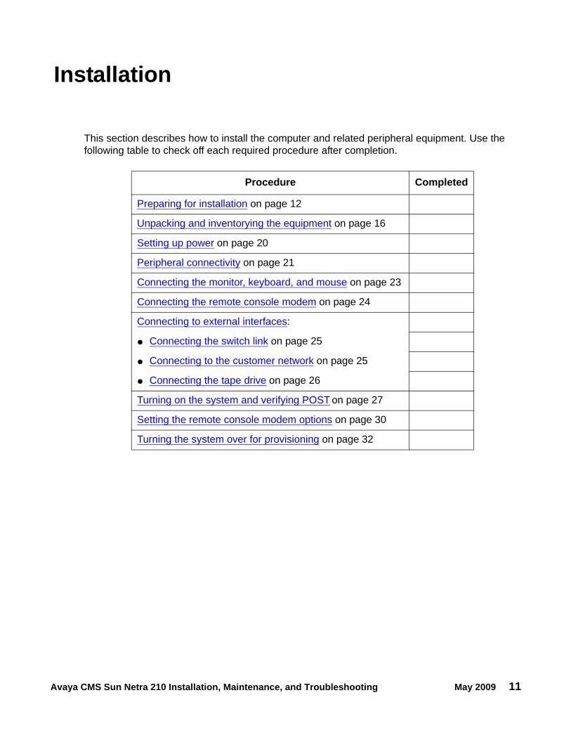
This section describes how to install the computer and related peripheral equipment. Use the following table to check off each required procedure after completion.
Procedure Completed
Preparing for installation on page 12
Unpacking and inventorying the equipment on page 16
Setting up power on page 20
Peripheral connectivity on page 21
Connecting the monitor, keyboard, and mouse on page 23
Connecting the remote console modem on page 24
Connecting to external interfaces:
● Connecting the switch link on page 25
● Connecting to the customer network on page 25
● Connecting the tape drive on page 26
Turning on the system and verifying POST on page 27
Setting the remote console modem options on page 30
Turning the system over for provisioning on page 32
Installation
12 Avaya CMS Sun Netra 210 Installation, Maintenance, and Troubleshooting May 2009
Preparing for installationThis section contains the following information that will help you prepare for the computer installation:
● Safety precautions on page 12
● System precautions on page 13
● Required tools on page 14
● Electrical specifications on page 14
● Physical specifications on page 14
● Environmental specifications on page 15
● Noise specifications on page 15
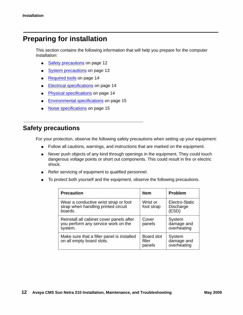
Safety precautionsFor your protection, observe the following safety precautions when setting up your equipment:
● Follow all cautions, warnings, and instructions that are marked on the equipment.
● Never push objects of any kind through openings in the equipment. They could touch dangerous voltage points or short out components. This could result in fire or electric shock.
● Refer servicing of equipment to qualified personnel.
● To protect both yourself and the equipment, observe the following precautions.
Precaution Item Problem
Wear a conductive wrist strap or foot strap when handling printed circuit boards.
Wrist or foot strap
Electro-Static Discharge (ESD)
Reinstall all cabinet cover panels after you perform any service work on the system.
Cover panels
System damage and overheating
Make sure that a filler panel is installed on all empty board slots.
Board slot filler panels
System damage and overheating
Preparing for installation
Avaya CMS Sun Netra 210 Installation, Maintenance, and Troubleshooting May 2009 13
System precautions
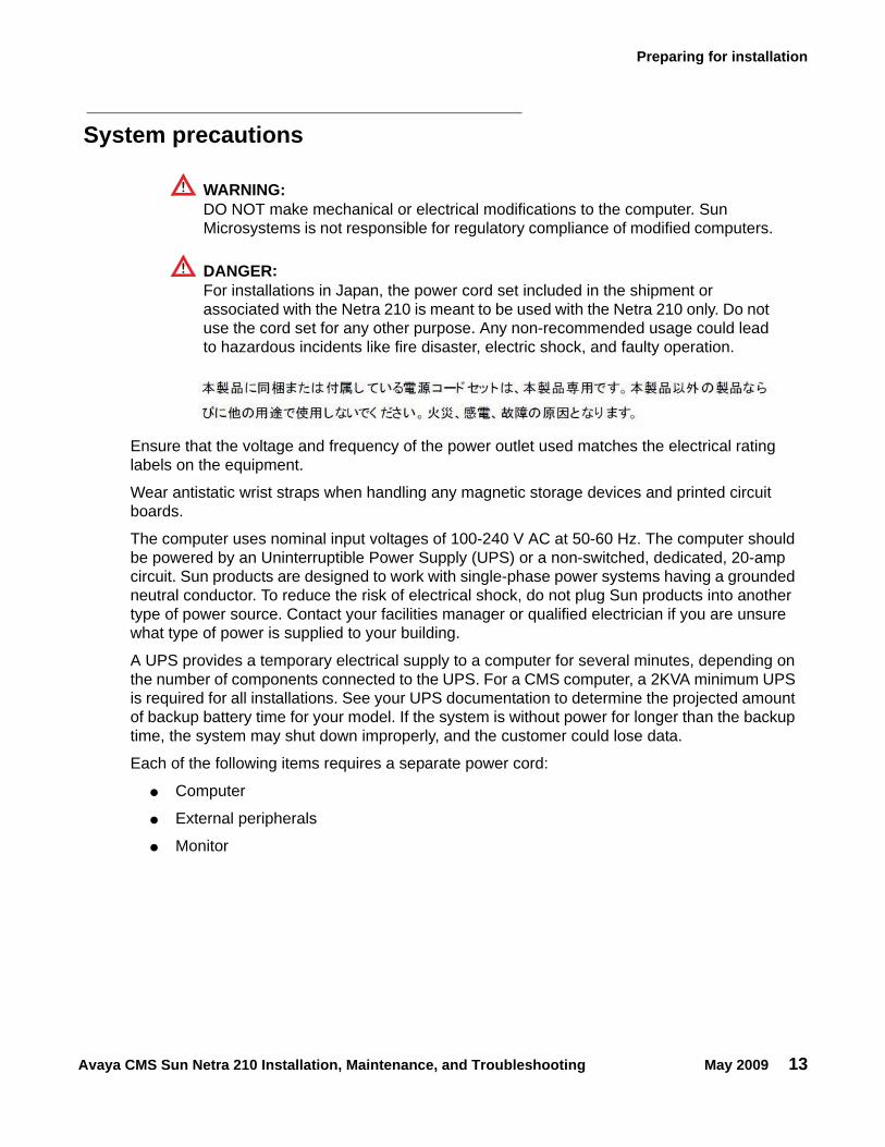
! WARNING:!
WARNING: DO NOT make mechanical or electrical modifications to the computer. Sun Microsystems is not responsible for regulatory compliance of modified computers.
! DANGER:!
DANGER: For installations in Japan, the power cord set included in the shipment or associated with the Netra 210 is meant to be used with the Netra 210 only. Do not use the cord set for any other purpose. Any non-recommended usage could lead to hazardous incidents like fire disaster, electric shock, and faulty operation.
Ensure that the voltage and frequency of the power outlet used matches the electrical rating labels on the equipment.
Wear antistatic wrist straps when handling any magnetic storage devices and printed circuit boards.
The computer uses nominal input voltages of 100-240 V AC at 50-60 Hz. The computer should be powered by an Uninterruptible Power Supply (UPS) or a non-switched, dedicated, 20-amp circuit. Sun products are designed to work with single-phase power systems having a grounded neutral conductor. To reduce the risk of electrical shock, do not plug Sun products into another type of power source. Contact your facilities manager or qualified electrician if you are unsure what type of power is supplied to your building.
A UPS provides a temporary electrical supply to a computer for several minutes, depending on the number of components connected to the UPS. For a CMS computer, a 2KVA minimum UPS is required for all installations. See your UPS documentation to determine the projected amount of backup battery time for your model. If the system is without power for longer than the backup time, the system may shut down improperly, and the customer could lose data.
Each of the following items requires a separate power cord:
● Computer
● External peripherals
● Monitor
Installation
14 Avaya CMS Sun Netra 210 Installation, Maintenance, and Troubleshooting May 2009
Required toolsYou need the following tools to do the installation:
● Phillips #2 screwdriver
● ESD grounding wrist strap
● Antistatic mat
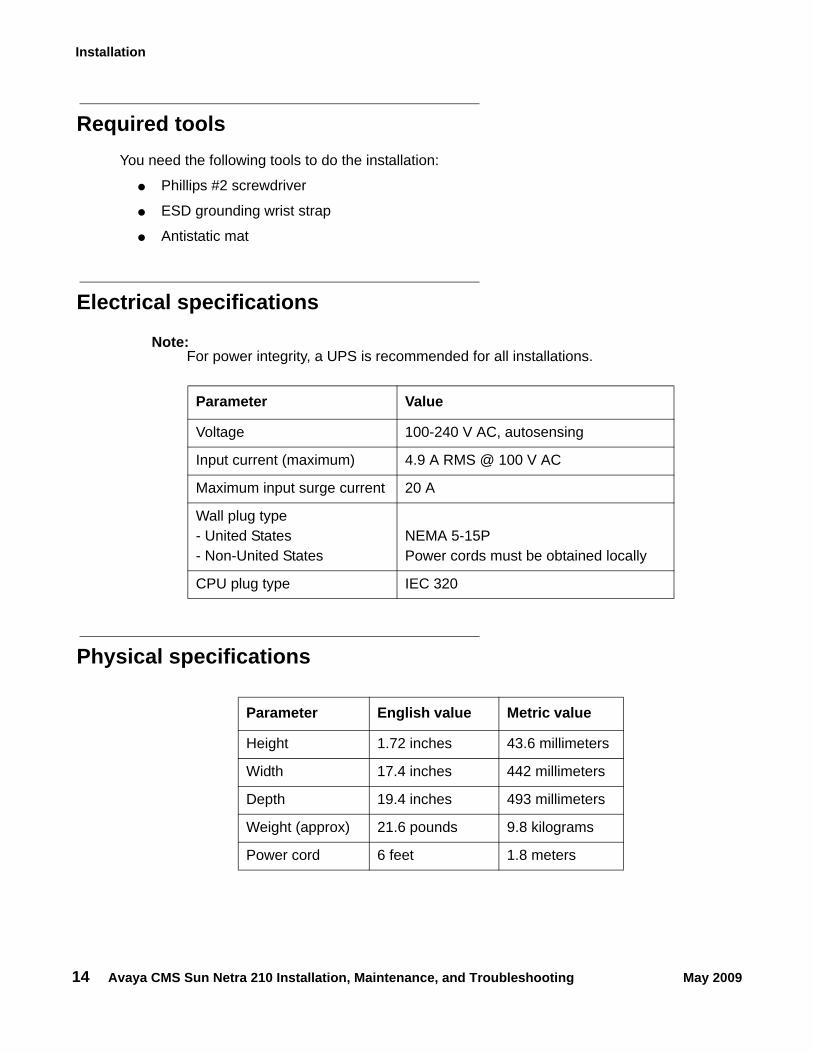
Electrical specifications
Note:Note: For power integrity, a UPS is recommended for all installations.
Physical specifications
Parameter Value
Voltage 100-240 V AC, autosensing
Input current (maximum) 4.9 A RMS @ 100 V AC
Maximum input surge current 20 A
Wall plug type- United States- Non-United States
NEMA 5-15PPower cords must be obtained locally
CPU plug type IEC 320
Parameter English value Metric value
Height 1.72 inches 43.6 millimeters
Width 17.4 inches 442 millimeters
Depth 19.4 inches 493 millimeters
Weight (approx) 21.6 pounds 9.8 kilograms
Power cord 6 feet 1.8 meters
Preparing for installation
Avaya CMS Sun Netra 210 Installation, Maintenance, and Troubleshooting May 2009 15
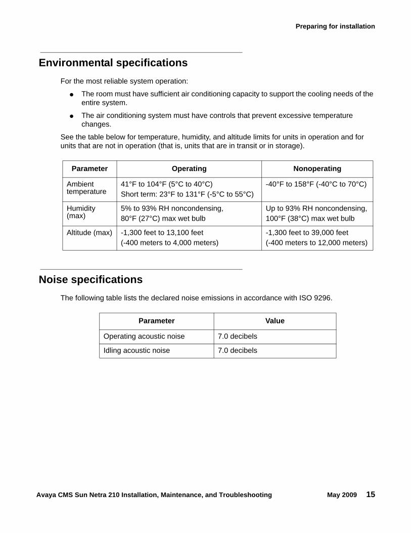
Environmental specificationsFor the most reliable system operation:
● The room must have sufficient air conditioning capacity to support the cooling needs of the entire system.
● The air conditioning system must have controls that prevent excessive temperature changes.
See the table below for temperature, humidity, and altitude limits for units in operation and for units that are not in operation (that is, units that are in transit or in storage).
Noise specificationsThe following table lists the declared noise emissions in accordance with ISO 9296.
Parameter Operating Nonoperating
Ambient temperature
41°F to 104°F (5°C to 40°C)Short term: 23°F to 131°F (-5°C to 55°C)
-40°F to 158°F (-40°C to 70°C)
Humidity (max)
5% to 93% RH noncondensing, 80°F (27°C) max wet bulb
Up to 93% RH noncondensing,100°F (38°C) max wet bulb
Altitude (max) -1,300 feet to 13,100 feet (-400 meters to 4,000 meters)
-1,300 feet to 39,000 feet(-400 meters to 12,000 meters)
Parameter Value
Operating acoustic noise 7.0 decibels
Idling acoustic noise 7.0 decibels
Installation
16 Avaya CMS Sun Netra 210 Installation, Maintenance, and Troubleshooting May 2009
Unpacking and inventorying the equipment
! WARNING:!
WARNING: Never move the computer when the power is on. Excessive movement can cause catastrophic disk drive failure. Always power the system off before moving the computer.
! WARNING:!
WARNING: Always wear an electrostatic discharge (ESD) strap when handling internal components.
CAUTION:!
CAUTION: Always have up-to-date system backups before turning off and moving the computer.
Inspect all shipping cartons for evidence of physical damage. If a shipping carton is damaged, request that the carrier representative be present before the carton is opened.
Unpack the computer and associated peripheral equipment. Compare the contents of the carton to the shipping inventory list to verify that all equipment was delivered.
In the United States, contact Avaya technical support if any parts are defective on arrival. Contact Avaya customer service if any parts are missing.
Outside of the United States, contact your Avaya representative or distributor if any parts are missing or defective.
This section includes the following topics:
● Parts list on page 17
● Determining the computer model on page 18
● Computer layout on page 19
Unpacking and inventorying the equipment
Avaya CMS Sun Netra 210 Installation, Maintenance, and Troubleshooting May 2009 17
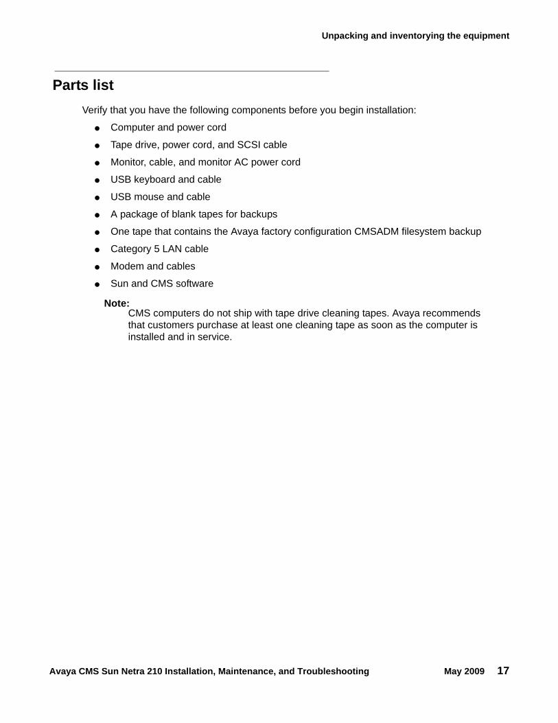
Parts listVerify that you have the following components before you begin installation:
● Computer and power cord
● Tape drive, power cord, and SCSI cable
● Monitor, cable, and monitor AC power cord
● USB keyboard and cable
● USB mouse and cable
● A package of blank tapes for backups
● One tape that contains the Avaya factory configuration CMSADM filesystem backup
● Category 5 LAN cable
● Modem and cables
● Sun and CMS software
Note:Note: CMS computers do not ship with tape drive cleaning tapes. Avaya recommends
that customers purchase at least one cleaning tape as soon as the computer is installed and in service.
Installation
18 Avaya CMS Sun Netra 210 Installation, Maintenance, and Troubleshooting May 2009
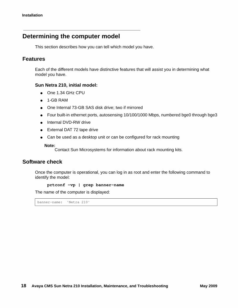
Determining the computer modelThis section describes how you can tell which model you have.
Features
Each of the different models have distinctive features that will assist you in determining what model you have.
Sun Netra 210, initial model:● One 1.34 GHz CPU
● 1-GB RAM
● One Internal 73-GB SAS disk drive; two if mirrored
● Four built-in ethernet ports, autosensing 10/100/1000 Mbps, numbered bge0 through bge3
● Internal DVD-RW drive
● External DAT 72 tape drive
● Can be used as a desktop unit or can be configured for rack mounting
Note:Note: Contact Sun Microsystems for information about rack mounting kits.
Software check
Once the computer is operational, you can log in as root and enter the following command to identify the model:
prtconf -vp | grep banner-name
The name of the computer is displayed:
banner-name: 'Netra 210'
Unpacking and inventorying the equipment
Avaya CMS Sun Netra 210 Installation, Maintenance, and Troubleshooting May 2009 19
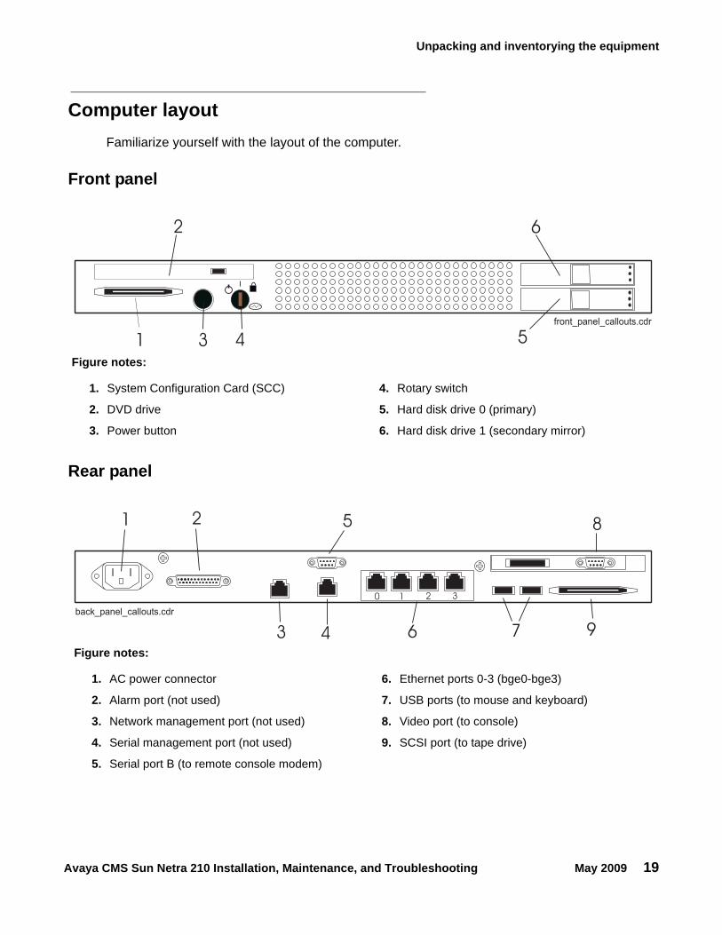
Computer layoutFamiliarize yourself with the layout of the computer.
Front panel
Rear panel
1
2
3 4 5
6
cpcxsub2 LJK 071101front_panel_callouts.cdr
Figure notes:
1. System Configuration Card (SCC) 4. Rotary switch
2. DVD drive 5. Hard disk drive 0 (primary)
3. Power button 6. Hard disk drive 1 (secondary mirror)
1 2
3 4
5
6 7
8
9
cpcxsub2 LJK 071101back_panel_callouts.cdr
0 1 2 3
Figure notes:
1. AC power connector 6. Ethernet ports 0-3 (bge0-bge3)
2. Alarm port (not used) 7. USB ports (to mouse and keyboard)
3. Network management port (not used) 8. Video port (to console)
4. Serial management port (not used) 9. SCSI port (to tape drive)
5. Serial port B (to remote console modem)
Installation
20 Avaya CMS Sun Netra 210 Installation, Maintenance, and Troubleshooting May 2009
Setting up powerTo set up the AC power:
1. Plug the IEC 320 end of the power cord into the AC connector.
For installations outside of the United States and Canada, obtain a power cord for your local configuration.
2. Plug the power cord from the computer into an outlet on the UPS.
A UPS provides a temporary electrical supply to a computer for several minutes, depending on the number of components connected to the UPS. For a CMS computer, a 2KVA minimum UPS is required for all installations. See your UPS documentation to determine the projected amount of backup battery time for your model. If the system is without power for longer than the backup time, the system may shut down improperly, and the customer could lose data.
If a UPS is not being used, you must use a grounded outlet on a dedicated 20-amp circuit.
! Important:Important: Do not turn on power at this time.
Peripheral connectivity
Avaya CMS Sun Netra 210 Installation, Maintenance, and Troubleshooting May 2009 21
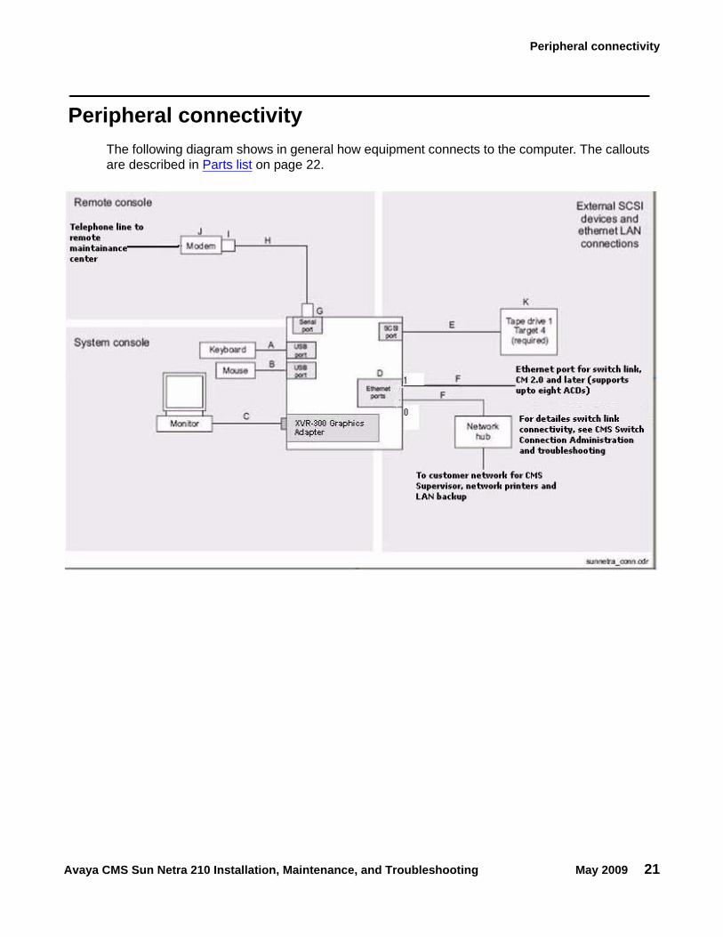
Peripheral connectivityThe following diagram shows in general how equipment connects to the computer. The callouts are described in Parts list on page 22.
Installation
22 Avaya CMS Sun Netra 210 Installation, Maintenance, and Troubleshooting May 2009
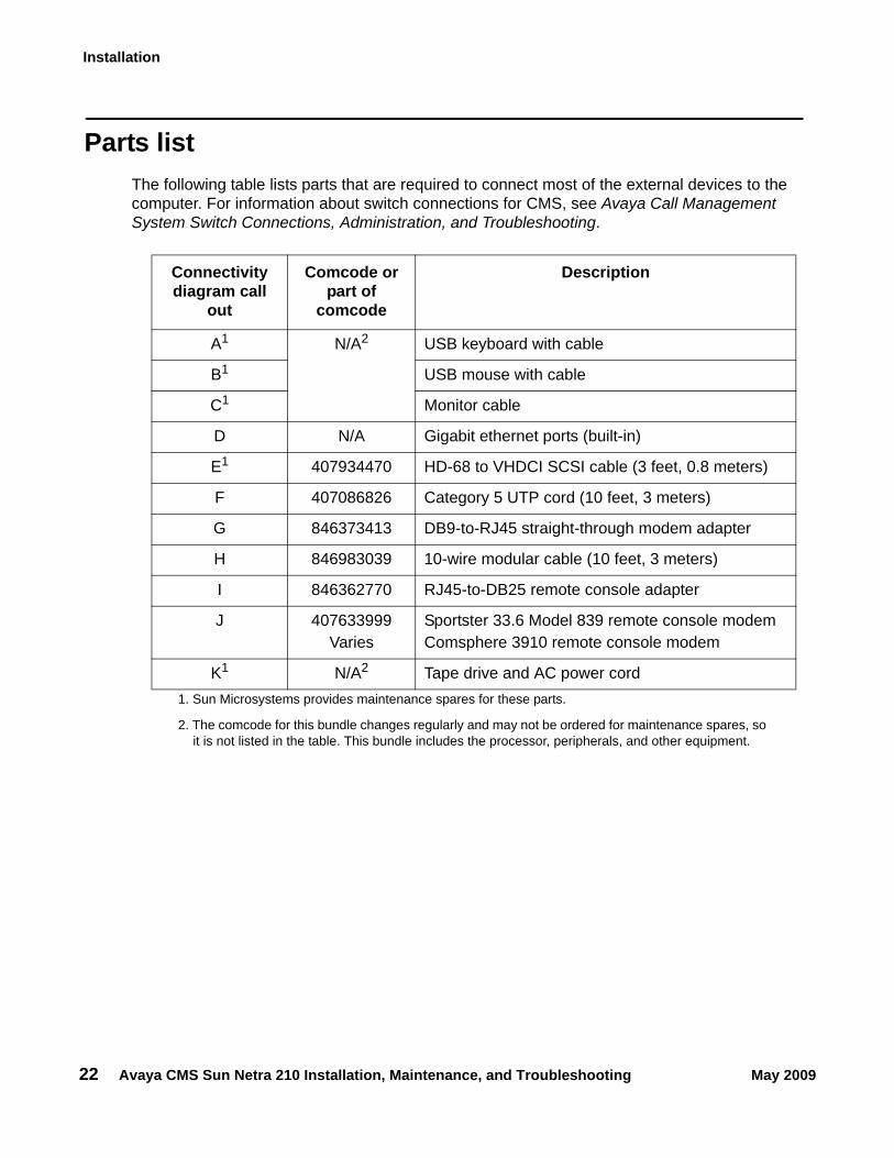
Parts listThe following table lists parts that are required to connect most of the external devices to the computer. For information about switch connections for CMS, see Avaya Call Management System Switch Connections, Administration, and Troubleshooting.
Connectivity diagram call
out
Comcode or part of
comcode
Description
A1
1. Sun Microsystems provides maintenance spares for these parts.
N/A2
2. The comcode for this bundle changes regularly and may not be ordered for maintenance spares, so it is not listed in the table. This bundle includes the processor, peripherals, and other equipment.
USB keyboard with cable
B1 USB mouse with cable
C1 Monitor cable
D N/A Gigabit ethernet ports (built-in)
E1 407934470 HD-68 to VHDCI SCSI cable (3 feet, 0.8 meters)
F 407086826 Category 5 UTP cord (10 feet, 3 meters)
G 846373413 DB9-to-RJ45 straight-through modem adapter
H 846983039 10-wire modular cable (10 feet, 3 meters)
I 846362770 RJ45-to-DB25 remote console adapter
J 407633999Varies
Sportster 33.6 Model 839 remote console modemComsphere 3910 remote console modem
K1 N/A2 Tape drive and AC power cord
Connecting the monitor, keyboard, and mouse
Avaya CMS Sun Netra 210 Installation, Maintenance, and Troubleshooting May 2009 23
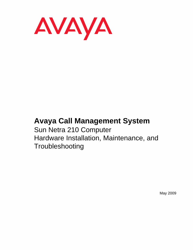
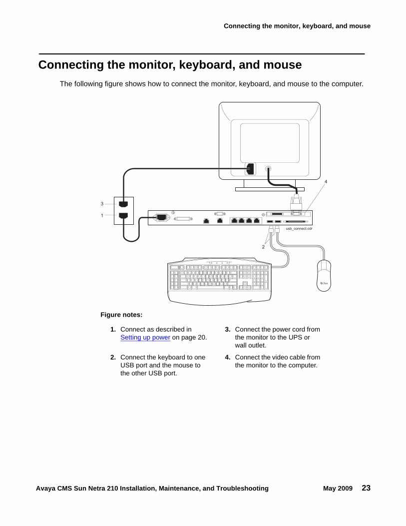
Connecting the monitor, keyboard, and mouseThe following figure shows how to connect the monitor, keyboard, and mouse to the computer.
usb_connect.cdr
1
3
2
4
Figure notes:
1. Connect as described in Setting up power on page 20.
3. Connect the power cord from the monitor to the UPS or wall outlet.
2. Connect the keyboard to one USB port and the mouse to the other USB port.
4. Connect the video cable from the monitor to the computer.
Installation
24 Avaya CMS Sun Netra 210 Installation, Maintenance, and Troubleshooting May 2009
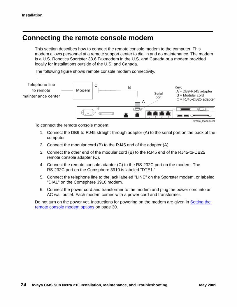
Connecting the remote console modemThis section describes how to connect the remote console modem to the computer. This modem allows personnel at a remote support center to dial in and do maintenance. The modem is a U.S. Robotics Sportster 33.6 Faxmodem in the U.S. and Canada or a modem provided locally for installations outside of the U.S. and Canada.
The following figure shows remote console modem connectivity..
To connect the remote console modem:
1. Connect the DB9-to-RJ45 straight-through adapter (A) to the serial port on the back of the computer.
2. Connect the modular cord (B) to the RJ45 end of the adapter (A).
3. Connect the other end of the modular cord (B) to the RJ45 end of the RJ45-to-DB25 remote console adapter (C).
4. Connect the remote console adapter (C) to the RS-232C port on the modem. The RS-232C port on the Comsphere 3910 is labeled "DTE1."
5. Connect the telephone line to the jack labeled "LINE" on the Sportster modem, or labeled "DIAL" on the Comsphere 3910 modem.
6. Connect the power cord and transformer to the modem and plug the power cord into an AC wall outlet. Each modem comes with a power cord and transformer.
Do not turn on the power yet. Instructions for powering on the modem are given in Setting the remote console modem options on page 30.
Modem
Telephone line
to remote
maintenance center
BC
ModemKey:A = DB9-RJ45 adapterB = Modular cordC = RJ45-DB25 adapter
Serialport
A
remote_modem.cdr
0 1 2 3
Connecting to external interfaces
Avaya CMS Sun Netra 210 Installation, Maintenance, and Troubleshooting May 2009 25
Connecting to external interfacesThis section describes the external interfaces connected to the computer. This section includes the following topics:
● Connecting the switch link on page 25
● Connecting to the customer network on page 25
● Connecting the tape drive on page 26
Connecting the switch linkThe CMS computer uses TCP/IP over a local area network (LAN) at 10/100 Mbps for a connection to the switch. One CMS computer can collect data from several switches. To the CMS computer, each switch represents one ACD.
Avaya recommends that you use ethernet port 1 for this connection.
For detailed information about how to connect and administer the switch link, see Avaya Call Management System Switch Connections, Administration, and Troubleshooting.
Connecting to the customer networkThe computer supports built-in ethernet ports that support network speeds of 10/100/1000 Mbps. However, for CMS installations, Avaya recommends that you only use speeds at the 10/100 Mbps speed range. This ethernet connection is used for CMS Supervisor, network printers, and LAN backup.
Avaya recommends that you use ethernet port 0 for this connection.
Installation
26 Avaya CMS Sun Netra 210 Installation, Maintenance, and Troubleshooting May 2009
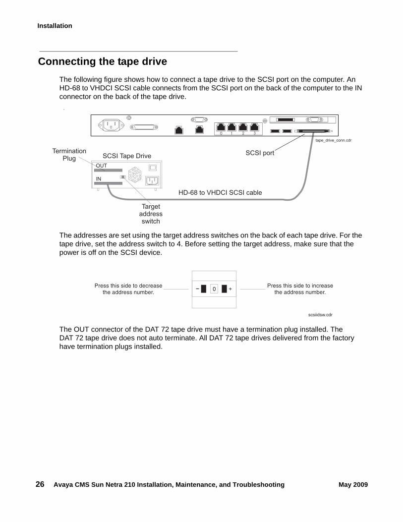
Connecting the tape driveThe following figure shows how to connect a tape drive to the SCSI port on the computer. An HD-68 to VHDCI SCSI cable connects from the SCSI port on the back of the computer to the IN connector on the back of the tape drive.
.
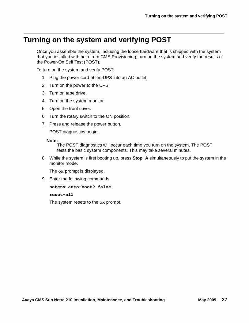
The addresses are set using the target address switches on the back of each tape drive. For the tape drive, set the address switch to 4. Before setting the target address, make sure that the power is off on the SCSI device.
The OUT connector of the DAT 72 tape drive must have a termination plug installed. The DAT 72 tape drive does not auto terminate. All DAT 72 tape drives delivered from the factory have termination plugs installed.
SCSI port
Targetaddressswitch
tape_drive_conn.cdr
HD-68 to VHDCI SCSI cable
SCSI Tape Drive
IN
OUT
TerminationPlug
0 1 2 3
Press this side to increasethe address number.
Press this side to decreasethe address number.
+
0
scsiidsw.cdr
Turning on the system and verifying POST
Avaya CMS Sun Netra 210 Installation, Maintenance, and Troubleshooting May 2009 27
Turning on the system and verifying POSTOnce you assemble the system, including the loose hardware that is shipped with the system that you installed with help from CMS Provisioning, turn on the system and verify the results of the Power-On Self Test (POST).
To turn on the system and verify POST:
1. Plug the power cord of the UPS into an AC outlet.
2. Turn on the power to the UPS.
3. Turn on tape drive.
4. Turn on the system monitor.
5. Open the front cover.
6. Turn the rotary switch to the ON position.
7. Press and release the power button.
POST diagnostics begin.
Note:Note: The POST diagnostics will occur each time you turn on the system. The POST
tests the basic system components. This may take several minutes.
8. While the system is first booting up, press Stop+A simultaneously to put the system in the monitor mode.
The ok prompt is displayed.
9. Enter the following commands:
setenv auto-boot? false
reset-all
The system resets to the ok prompt.
Installation
28 Avaya CMS Sun Netra 210 Installation, Maintenance, and Troubleshooting May 2009
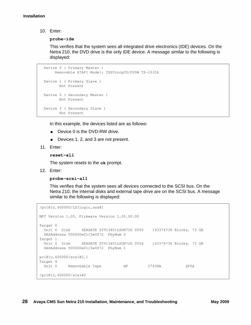
10. Enter:
probe-ide
This verifies that the system sees all integrated drive electronics (IDE) devices. On the Netra 210, the DVD drive is the only IDE device. A message similar to the following is displayed:
In this example, the devices listed are as follows:
● Device 0 is the DVD-RW drive.
● Devices 1, 2, and 3 are not present.
11. Enter:
reset-all
The system resets to the ok prompt.
12. Enter:
probe-scsi-all
This verifies that the system sees all devices connected to the SCSI bus. On the Netra 210, the internal disks and external tape drive are on the SCSI bus. A message similar to the following is displayed:
Device 0 ( Primary Master )Removable ATAPI Model: TSSTcorpCD/DVDW TS-L532A
Device 1 ( Primary Slave )Not Present
Device 2 ( Secondary Master )Not Present
Device 3 ( Secondary Slave )Not Present
/pci@1c,600000/LSILogic,sas@1
MPT Version 1.05, Firmware Version 1.05.00.00
Target 0Unit 0 Disk SEAGATE ST913401LSUN72G 0556 143374738 Blocks, 73 GBSASAddress 500000e0115e0072 PhyNum 0
Target 1Unit 0 Disk SEAGATE ST913401LSUN72G 0556 143374738 Blocks, 73 GBSASAddress 500000e0115e0072 PhyNum 1
pci@1c,600000/scsi@2,1Target 4
Unit 0 Removeable Tape HP C7438A ZP5A
/pci@1c,600000/scsi@2
Turning on the system and verifying POST
Avaya CMS Sun Netra 210 Installation, Maintenance, and Troubleshooting May 2009 29
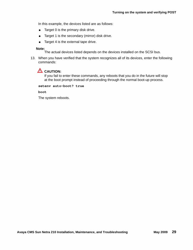
In this example, the devices listed are as follows:
● Target 0 is the primary disk drive.
● Target 1 is the secondary (mirror) disk drive.
● Target 4 is the external tape drive.
Note:Note: The actual devices listed depends on the devices installed on the SCSI bus.
13. When you have verified that the system recognizes all of its devices, enter the following commands:
CAUTION:!
CAUTION: If you fail to enter these commands, any reboots that you do in the future will stop at the boot prompt instead of proceeding through the normal boot-up process.
setenv auto-boot? true
boot
The system reboots.
Installation
30 Avaya CMS Sun Netra 210 Installation, Maintenance, and Troubleshooting May 2009
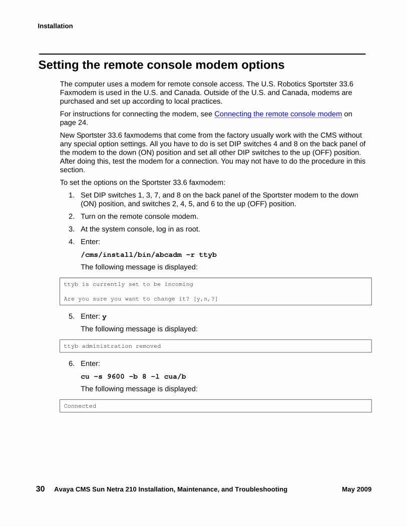
Setting the remote console modem optionsThe computer uses a modem for remote console access. The U.S. Robotics Sportster 33.6 Faxmodem is used in the U.S. and Canada. Outside of the U.S. and Canada, modems are purchased and set up according to local practices.
For instructions for connecting the modem, see Connecting the remote console modem on page 24.
New Sportster 33.6 faxmodems that come from the factory usually work with the CMS without any special option settings. All you have to do is set DIP switches 4 and 8 on the back panel of the modem to the down (ON) position and set all other DIP switches to the up (OFF) position. After doing this, test the modem for a connection. You may not have to do the procedure in this section.
To set the options on the Sportster 33.6 faxmodem:
1. Set DIP switches 1, 3, 7, and 8 on the back panel of the Sportster modem to the down (ON) position, and switches 2, 4, 5, and 6 to the up (OFF) position.
2. Turn on the remote console modem.
3. At the system console, log in as root.
4. Enter:
/cms/install/bin/abcadm -r ttyb
The following message is displayed:
5. Enter: y
The following message is displayed:
6. Enter:
cu -s 9600 -b 8 -l cua/b
The following message is displayed:
ttyb is currently set to be incoming
Are you sure you want to change it? [y,n,?]
ttyb administration removed
Connected
Setting the remote console modem options
Avaya CMS Sun Netra 210 Installation, Maintenance, and Troubleshooting May 2009 31
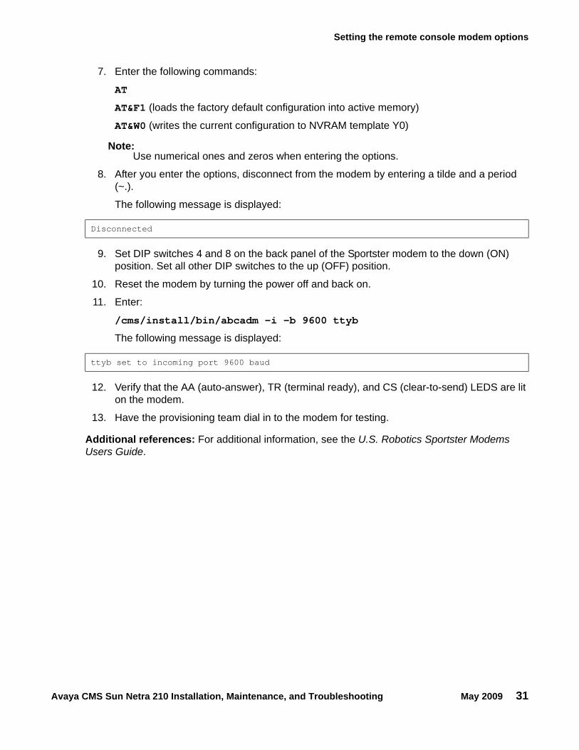
7. Enter the following commands:
AT
AT&F1 (loads the factory default configuration into active memory)
AT&W0 (writes the current configuration to NVRAM template Y0)
Note:Note: Use numerical ones and zeros when entering the options.
8. After you enter the options, disconnect from the modem by entering a tilde and a period (~.).
The following message is displayed:
9. Set DIP switches 4 and 8 on the back panel of the Sportster modem to the down (ON) position. Set all other DIP switches to the up (OFF) position.
10. Reset the modem by turning the power off and back on.
11. Enter:
/cms/install/bin/abcadm -i -b 9600 ttyb
The following message is displayed:
12. Verify that the AA (auto-answer), TR (terminal ready), and CS (clear-to-send) LEDS are lit on the modem.
13. Have the provisioning team dial in to the modem for testing.
Additional references: For additional information, see the U.S. Robotics Sportster Modems Users Guide.
Disconnected
ttyb set to incoming port 9600 baud
Installation
32 Avaya CMS Sun Netra 210 Installation, Maintenance, and Troubleshooting May 2009
Turning the system over for provisioningAfter completing the physical installation of the system, the installation continues with software provisioning. This is often done with the support of the Avaya CMS Provisioning group. Provisioning the system consists of the following:
● Setting up CMS
● Authorizing features
● Adding logins and passwords
● Testing the software
To continue with provisioning, see the chapter "Turning the system over to the customer" in the CMS software installation, maintenance, and troubleshooting document for your CMS release.
Avaya CMS Sun Netra 210 Installation, Maintenance, and Troubleshooting May 2009 33
Maintenance
This section describes the following maintenance procedures:
● Precautions on page 34
● Computer layout on page 35
● Turning the computer off and on on page 37
● Using an ESD wrist strap on page 38
● Replacing the video card on page 38
● Maintaining disk drives on page 39
● Replacing the DVD-RW drive on page 48
● Maintaining tape drives on page 49
● Adding memory and replacing the CPU on page 55
● Using the System Configuration Card (SCC) on page 55
Maintenance
34 Avaya CMS Sun Netra 210 Installation, Maintenance, and Troubleshooting May 2009
Precautions
! DANGER:!
DANGER: Hazardous energy levels are present inside the system when the system remains connected to a power source. Be sure to follow the safety procedures in the owner's guide or service manual.
! WARNING:!
WARNING: Before replacing any component in the system, you must turn off the computer and disconnect the AC power cord.
CAUTION:!
CAUTION: Printed circuit boards and hard disk drives contain electronic components that are extremely sensitive to static electricity. Ordinary amounts of static from your clothes or the work environment can destroy components. Do not touch the components or any metal parts without taking proper antistatic precautions. See Using an ESD wrist strap on page 38 for more information.
CAUTION:!
CAUTION: Avoid keeping the cover off for extended periods of time while the system is operating. The cover must be installed to prevent automatic thermal shutdown.
Computer layout
Avaya CMS Sun Netra 210 Installation, Maintenance, and Troubleshooting May 2009 35
Computer layoutThe following figures identify the basic hardware components of the computer:
● Front panel on page 35
● Rear panel on page 36
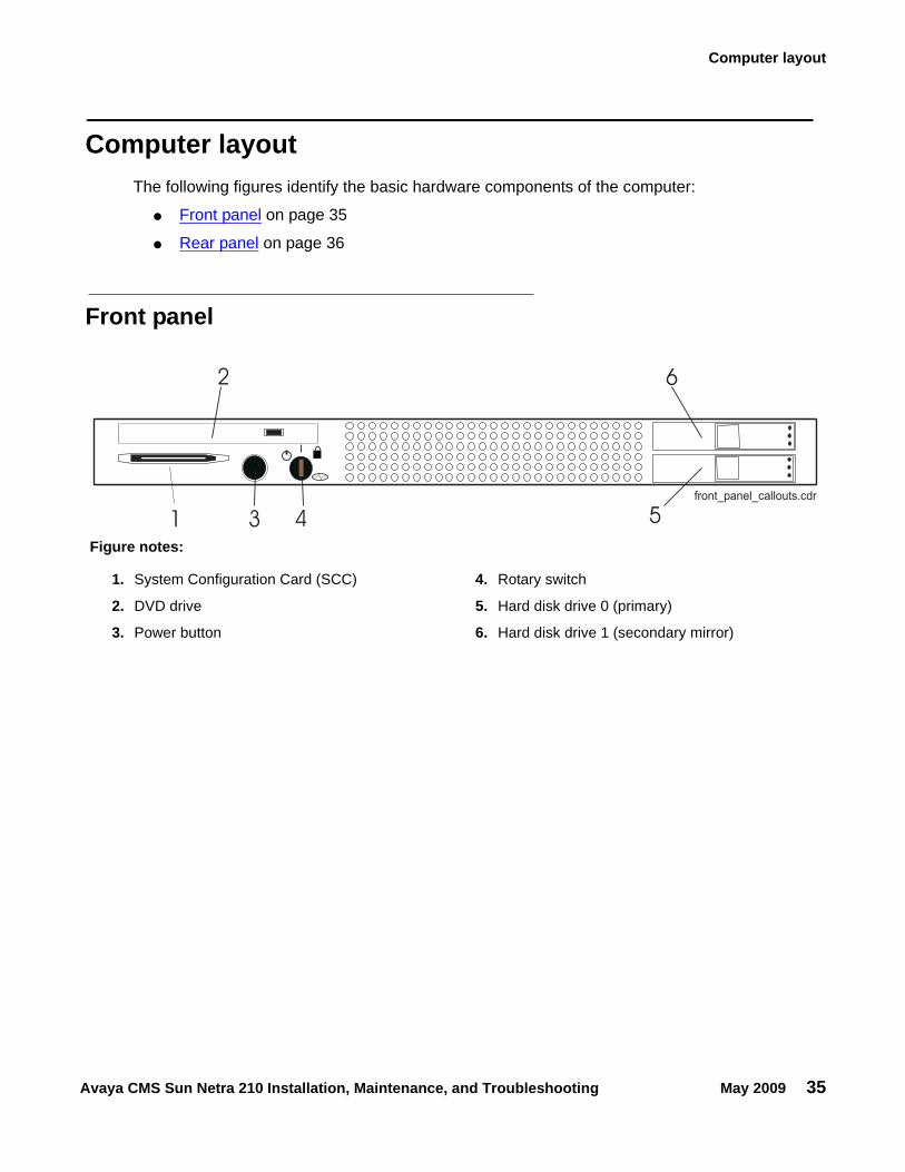
Front panel
1
2
3 4 5
6
cpcxsub2 LJK 071101front_panel_callouts.cdr
Figure notes:
1. System Configuration Card (SCC) 4. Rotary switch
2. DVD drive 5. Hard disk drive 0 (primary)
3. Power button 6. Hard disk drive 1 (secondary mirror)
Maintenance
36 Avaya CMS Sun Netra 210 Installation, Maintenance, and Troubleshooting May 2009
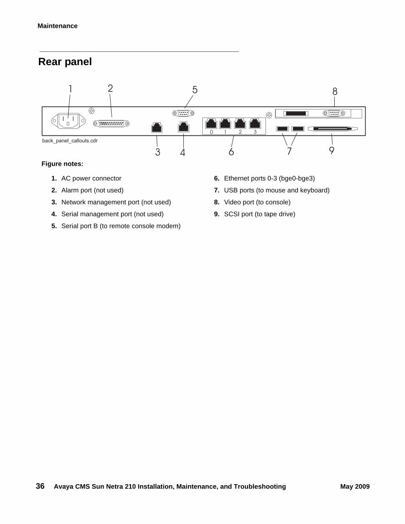
Rear panel
1 2
3 4
5
6 7
8
9
cpcxsub2 LJK 071101back_panel_callouts.cdr
0 1 2 3
Figure notes:
1. AC power connector 6. Ethernet ports 0-3 (bge0-bge3)
2. Alarm port (not used) 7. USB ports (to mouse and keyboard)
3. Network management port (not used) 8. Video port (to console)
4. Serial management port (not used) 9. SCSI port (to tape drive)
5. Serial port B (to remote console modem)
Turning the computer off and on
Avaya CMS Sun Netra 210 Installation, Maintenance, and Troubleshooting May 2009 37
Turning the computer off and onUse the following procedures to turn the computer off and on.
To turn off the computer:1. Log in to the system as root.
2. Enter:
/usr/sbin/shutdown -y -i0 -g0
This shuts down the system. The ok prompt is displayed at the local console.
3. Press and release the front panel power button to turn off the system.
Wait for the front panel Power/OK LED to turn off.
4. Turn the rotary switch to the Forced Off position.
! DANGER:!
DANGER: Be sure to turn the rotary switch to the Forced Off position before handling any internal components. Otherwise, it is possible for a user to restart the system remotely while you are working inside it.
5. Turn off the system monitor.
6. Turn off any external SCSI devices, starting with the device that is closest to the system and working toward the farthest device.
To turn on the computer:1. Turn on any external SCSI devices, starting with the device that is farthest from the system
and working toward the system.
2. Turn on the system monitor.
3. Turn the rotary switch to the normal On position.
4. Press and release the power button to the left of the rotary switch to turn on the system.
Note:Note: The POST diagnostics occurs each time that you turn on the system. The POST
tests the basic system components. This may take several minutes.
If the system is operating properly, a banner screen is displayed within about 5 minutes after it is turned on.
5. Log in to the system as root.
Maintenance
38 Avaya CMS Sun Netra 210 Installation, Maintenance, and Troubleshooting May 2009
Using an ESD wrist strapBefore you work on components inside the computer:
1. Make sure that the computer is plugged in to AC power.
2. Make sure that the power is off.
3. Attach the Electro-Static Discharge (ESD) wrist strap to the chassis frame and to your wrist.
4. Unplug the AC power cord.
Replacing the video cardContact Avaya support if the video card requires replacement. Sun technicians will replace the card.
Maintaining disk drives
Avaya CMS Sun Netra 210 Installation, Maintenance, and Troubleshooting May 2009 39
Maintaining disk drivesThis section includes the following topics:
● Prerequisites on page 39
● Disk drive compatibility with CMS loads on page 39
● Required references on page 39
● Replacing the primary disk drive on page 40
● Adding or replacing the secondary disk drive on page 42
● Setting up the disk drives on page 44
● Partitioning and formatting a disk on page 44
PrerequisitesIf possible, do a CMSADM backup before you add or replace a disk drive. See your CMS software installation, maintenance, and troubleshooting document for this procedure.
Disk drive compatibility with CMS loadsWhen a new or replacement disk drive is installed in an older system, the CMS load may not be compatible with the disk drive if the CMS configuration files have not been updated. These configuration files (/olds/disk.conf and /olds/olds-funcs) must be edited to add the correct information or must be replaced with files that contain the correct information. Contact the Avaya technical support organization for assistance.
Required referencesThe following references are required when doing procedures in this section:
● The CMS software installation, maintenance, and troubleshooting document for your CMS release
● Sun Netra 210 Service Manual at the Sun documentation Web site:
http://docs.sun.com
Maintenance
40 Avaya CMS Sun Netra 210 Installation, Maintenance, and Troubleshooting May 2009
Replacing the primary disk driveThis procedure describes how to replace the primary disk drive. If you are also adding or replacing the mirror disk drive, use these procedures in concert with Adding or replacing the secondary disk drive on page 42 while you have the front cover open.
This section includes the following topics:
● Removing the primary disk drive on page 40
● Installing the new primary disk drive on page 40
● Turning on the system on page 41
Removing the primary disk drive
To remove the primary disk drive:
1. If you have not already done so, use the following command to shut down the computer:
/usr/sbin/shutdown -y -i0 -g0
This shuts down the system and the ok prompt is displayed.
2. Open the front cover.
3. Turn the power switch to the OFF position.
4. Locate the primary disk drive. The primary disk drive is labeled HDD0.
5. Press the drive button to release the drive latch.
6. Pull firmly on the drive latch to slide the drive out of the drive bay.
7. Set the drive aside on an antistatic mat.
8. Continue with Installing the new primary disk drive on page 40.
Installing the new primary disk drive
To install the new primary disk drive:
1. Remove the replacement hard drive from its shipping container and antistatic packaging.
2. Press the drive button to release the drive latch.
3. Orient the hard drive with the drive latch towards you, and the label facing up.
4. Carefully slide the drive into the drive bay by pressing on the area between the drive button and the drive status LEDs.
5. When you feel resistance, press firmly so that the drive latch begins to close.
6. Press the drive latch closed.
Maintaining disk drives
Avaya CMS Sun Netra 210 Installation, Maintenance, and Troubleshooting May 2009 41
7. Do one of the following procedures:
● If you are adding or replacing the secondary mirror disk drive, continue with Adding or replacing the secondary disk drive on page 42.
● If you are not adding or replacing the secondary mirror disk drive, continue with Turning on the system on page 41.
Turning on the system
To turn on the system:
1. Turn on the tape drive.
2. Turn on the system monitor.
3. Open the front cover.
4. Turn the rotary switch to the ON position.
5. Press and release the power button.
POST diagnostics begin.
6. Press Stop+A simultaneously after the console banner is displayed, but before the system starts booting.
7. Enter the following commands:
setenv auto-boot? false
reset-all
This resets the system and the ok prompt is displayed.
8. Enter:
probe-scsi
This checks to see that the system recognizes the new disk drive. If the new drive is not listed, make sure the disk drive is installed correctly.
9. Reboot the system by entering the following commands:
CAUTION:!
CAUTION: If you fail to enter these commands, any reboots that you do in the future will stop at the boot prompt instead of proceeding through the normal boot-up process.
setenv auto-boot? true
boot -r
The system reboots.
10. Continue with Setting up the disk drives on page 44.
Maintenance
42 Avaya CMS Sun Netra 210 Installation, Maintenance, and Troubleshooting May 2009
Adding or replacing the secondary disk driveThis section describes how to add or replace the secondary (mirror) disk drive in the computer.
This section includes the following topics:
● Removing the secondary disk drive on page 42
● Installing the new secondary disk drive on page 42
● Turning on the system on page 43
Removing the secondary disk drive
To remove the secondary disk drive:
1. If you have not already done so, use the following command to shut down the computer:
/usr/sbin/shutdown -y -i0 -g0
This shuts down the system and the ok prompt is displayed.
2. Open the front cover.
3. Turn the power switch to the OFF position.
4. Locate the secondary disk drive. The secondary disk drive is labeled HDD1.
5. Press the drive button to release the drive latch.
6. Pull firmly on the drive latch to slide the drive out of the drive bay.
7. Set the drive aside on an antistatic mat.
8. Continue with Installing the new secondary disk drive on page 42.
Installing the new secondary disk drive
To install the new secondary disk drive:
1. Remove the replacement hard drive from its shipping container and antistatic packaging.
2. Press the drive button to release the drive latch.
3. Orient the hard drive with the drive latch towards you, and the label facing up.
4. Carefully slide the drive into the drive bay by pressing on the area between the drive button and the drive status LEDs.
5. When you feel resistance, press firmly so that the drive latch begins to close.
6. Press the drive latch closed.
7. Continue with Turning on the system on page 43.
Maintaining disk drives
Avaya CMS Sun Netra 210 Installation, Maintenance, and Troubleshooting May 2009 43
Turning on the system
To turn on the system:
1. Turn on the tape drive.
2. Turn on the system monitor.
3. Open the front cover.
4. Turn the rotary switch to the ON position.
5. Press and release the power button.
POST diagnostics begin.
6. Press Stop+A simultaneously after the console banner is displayed, but before the system starts booting.
7. Enter the following commands:
setenv auto-boot? false
reset-all
This resets the system and the ok prompt is displayed.
8. Enter:
probe-scsi
This checks to see that the system recognizes the new disk drive. If the new drive is not listed, make sure the disk drive is installed correctly.
9. Reboot the system by entering the following commands:
CAUTION:!
CAUTION: If you fail to enter these commands, any reboots that you do in the future will stop at the boot prompt instead of proceeding through the normal boot-up process.
setenv auto-boot? true
boot -r
The system reboots.
10. Continue with Setting up the disk drives on page 44.
Maintenance
44 Avaya CMS Sun Netra 210 Installation, Maintenance, and Troubleshooting May 2009
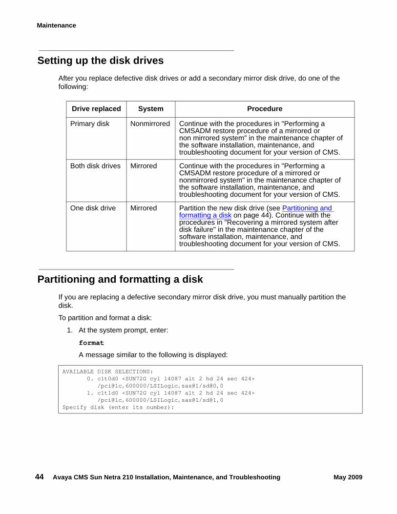
Setting up the disk drivesAfter you replace defective disk drives or add a secondary mirror disk drive, do one of the following:
Partitioning and formatting a diskIf you are replacing a defective secondary mirror disk drive, you must manually partition the disk.
To partition and format a disk:
1. At the system prompt, enter:
format
A message similar to the following is displayed:
Drive replaced System Procedure
Primary disk Nonmirrored Continue with the procedures in "Performing a CMSADM restore procedure of a mirrored or non mirrored system" in the maintenance chapter of the software installation, maintenance, and troubleshooting document for your version of CMS.
Both disk drives Mirrored Continue with the procedures in "Performing a CMSADM restore procedure of a mirrored or nonmirrored system" in the maintenance chapter of the software installation, maintenance, and troubleshooting document for your version of CMS.
One disk drive Mirrored Partition the new disk drive (see Partitioning and formatting a disk on page 44). Continue with the procedures in "Recovering a mirrored system after disk failure" in the maintenance chapter of the software installation, maintenance, and troubleshooting document for your version of CMS.
AVAILABLE DISK SELECTIONS: 0. c1t0d0 <SUN72G cyl 14087 alt 2 hd 24 sec 424> /pci@1c,600000/LSILogic,sas@1/sd@0,0 1. c1t1d0 <SUN72G cyl 14087 alt 2 hd 24 sec 424> /pci@1c,600000/LSILogic,sas@1/sd@1,0Specify disk (enter its number):
Maintaining disk drives
Avaya CMS Sun Netra 210 Installation, Maintenance, and Troubleshooting May 2009 45
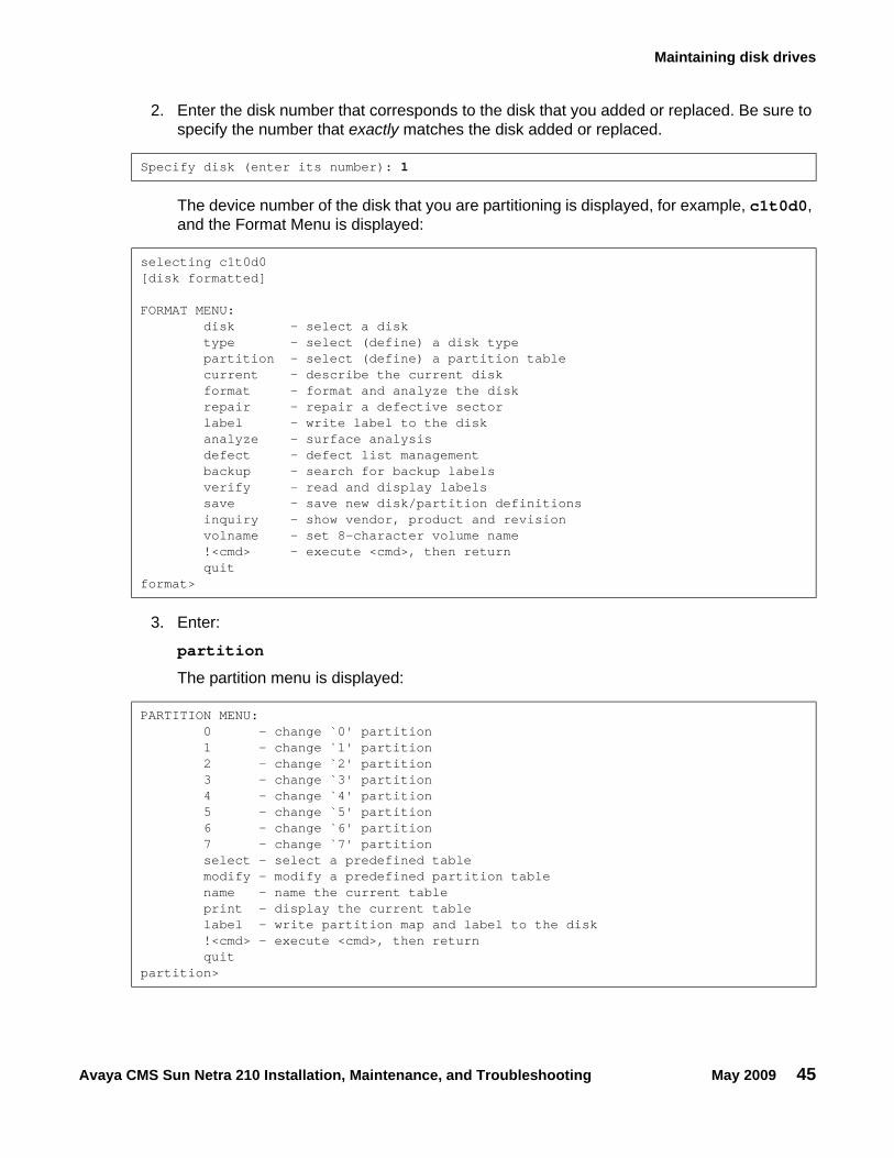
2. Enter the disk number that corresponds to the disk that you added or replaced. Be sure to specify the number that exactly matches the disk added or replaced.
The device number of the disk that you are partitioning is displayed, for example, c1t0d0, and the Format Menu is displayed:
3. Enter:
partition
The partition menu is displayed:
Specify disk (enter its number): 1
selecting c1t0d0[disk formatted]
FORMAT MENU: disk - select a disk type - select (define) a disk type partition - select (define) a partition table current - describe the current disk format - format and analyze the disk repair - repair a defective sector label - write label to the disk analyze - surface analysis defect - defect list management backup - search for backup labels verify - read and display labels save - save new disk/partition definitions inquiry - show vendor, product and revision volname - set 8-character volume name !<cmd> - execute <cmd>, then return quitformat>
PARTITION MENU: 0 - change `0' partition 1 - change `1' partition 2 - change `2' partition 3 - change `3' partition 4 - change `4' partition 5 - change `5' partition 6 - change `6' partition 7 - change `7' partition select - select a predefined table modify - modify a predefined partition table name - name the current table print - display the current table label - write partition map and label to the disk !<cmd> - execute <cmd>, then return quitpartition>
Maintenance
46 Avaya CMS Sun Netra 210 Installation, Maintenance, and Troubleshooting May 2009
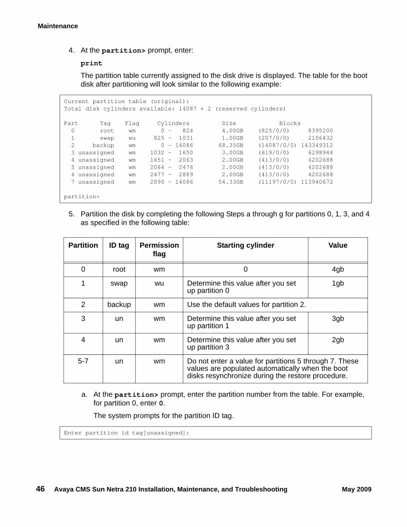
4. At the partition> prompt, enter:
The partition table currently assigned to the disk drive is displayed. The table for the boot disk after partitioning will look similar to the following example:
5. Partition the disk by completing the following Steps a through g for partitions 0, 1, 3, and 4 as specified in the following table:
a. At the partition> prompt, enter the partition number from the table. For example, for partition 0, enter 0.
The system prompts for the partition ID tag.
Current partition table (original):Total disk cylinders available: 14087 + 2 (reserved cylinders)
Part Tag Flag Cylinders Size Blocks 0 root wm 0 - 824 4.00GB (825/0/0) 8395200 1 swap wu 825 - 1031 1.00GB (207/0/0) 2106432 2 backup wm 0 - 14086 68.35GB (14087/0/0) 143349312 3 unassigned wm 1032 - 1650 3.00GB (619/0/0) 6298944 4 unassigned wm 1651 - 2063 2.00GB (413/0/0) 4202688 5 unassigned wm 2064 - 2476 2.00GB (413/0/0) 4202688 6 unassigned wm 2477 - 2889 2.00GB (413/0/0) 4202688 7 unassigned wm 2890 - 14086 54.33GB (11197/0/0) 113940672
partition>
Partition ID tag Permission flag
Starting cylinder Value
0 root wm 0 4gb
1 swap wu Determine this value after you set up partition 0
1gb
2 backup wm Use the default values for partition 2.
3 un wm Determine this value after you set up partition 1
3gb
4 un wm Determine this value after you set up partition 3
2gb
5-7 un wm Do not enter a value for partitions 5 through 7. These values are populated automatically when the boot disks resynchronize during the restore procedure.
Enter partition id tag[unassigned]:
Maintaining disk drives
Avaya CMS Sun Netra 210 Installation, Maintenance, and Troubleshooting May 2009 47
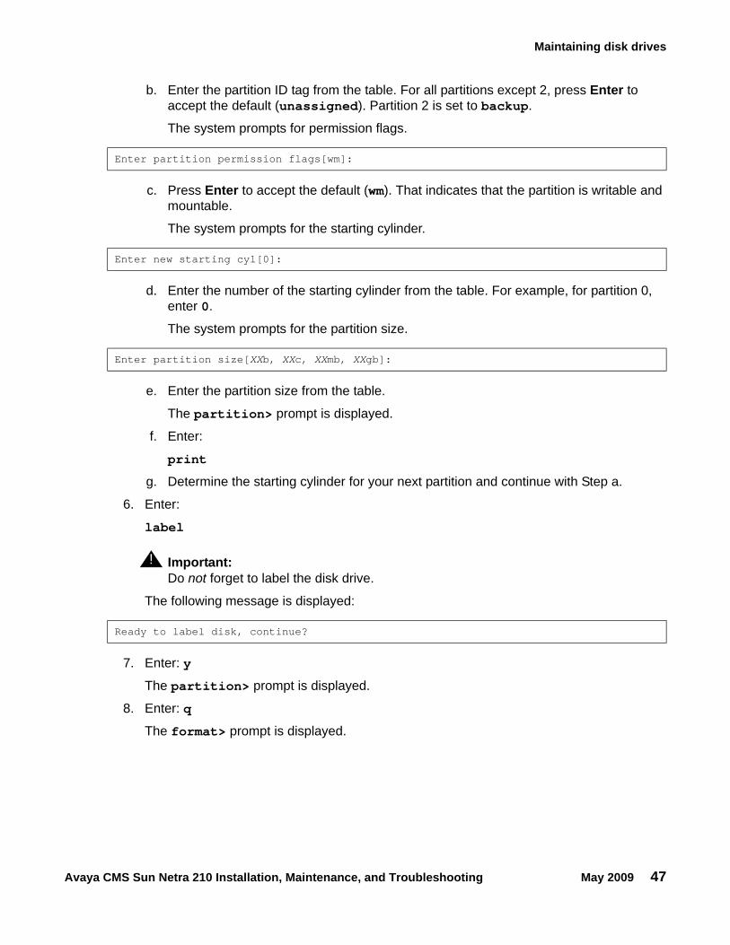
b. Enter the partition ID tag from the table. For all partitions except 2, press Enter to accept the default (unassigned). Partition 2 is set to backup.
The system prompts for permission flags.
c. Press Enter to accept the default (wm). That indicates that the partition is writable and mountable.
The system prompts for the starting cylinder.
d. Enter the number of the starting cylinder from the table. For example, for partition 0, enter 0.
The system prompts for the partition size.
e. Enter the partition size from the table.
The partition> prompt is displayed.
f. Enter:
g. Determine the starting cylinder for your next partition and continue with Step a.
6. Enter:
label
! Important:Important: Do not forget to label the disk drive.
The following message is displayed:
7. Enter: y
The partition> prompt is displayed.
8. Enter: q
The format> prompt is displayed.
Enter partition permission flags[wm]:
Enter new starting cyl[0]:
Enter partition size[XXb, XXc, XXmb, XXgb]:
Ready to label disk, continue?
Maintenance
48 Avaya CMS Sun Netra 210 Installation, Maintenance, and Troubleshooting May 2009
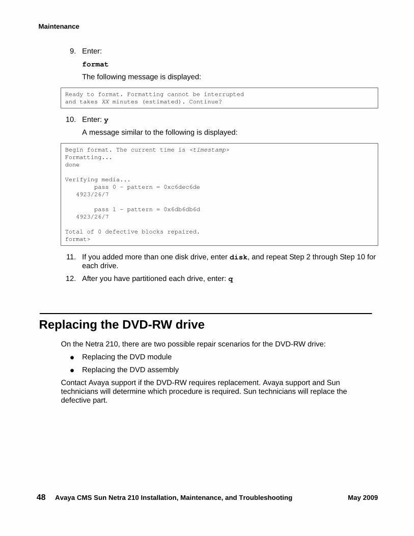
9. Enter:
format
The following message is displayed:
10. Enter: y
A message similar to the following is displayed:
11. If you added more than one disk drive, enter disk, and repeat Step 2 through Step 10 for each drive.
12. After you have partitioned each drive, enter: q
Replacing the DVD-RW driveOn the Netra 210, there are two possible repair scenarios for the DVD-RW drive:
● Replacing the DVD module
● Replacing the DVD assembly
Contact Avaya support if the DVD-RW requires replacement. Avaya support and Sun technicians will determine which procedure is required. Sun technicians will replace the defective part.
Ready to format. Formatting cannot be interruptedand takes XX minutes (estimated). Continue?
Begin format. The current time is <timestamp>Formatting...done
Verifying media...pass 0 - pattern = 0xc6dec6de
4923/26/7
pass 1 - pattern = 0x6db6db6d4923/26/7
Total of 0 defective blocks repaired.format>
Maintaining tape drives
Avaya CMS Sun Netra 210 Installation, Maintenance, and Troubleshooting May 2009 49
Maintaining tape drivesThis section include the following topics:
● Tape drive compatibility on page 49
● Ordering tapes on page 49
● Cleaning the tape drive on page 50
● Adding, removing, or replacing tape drives on page 51
Tape drive compatibilityWhen adding a newer model tape drive to a system, you may have to edit the /kernel/drv/st.conf file to add information about the new tape drive. If editing the file is required, you will receive a Design Change Letter (DCL) instructing you how to change the file.
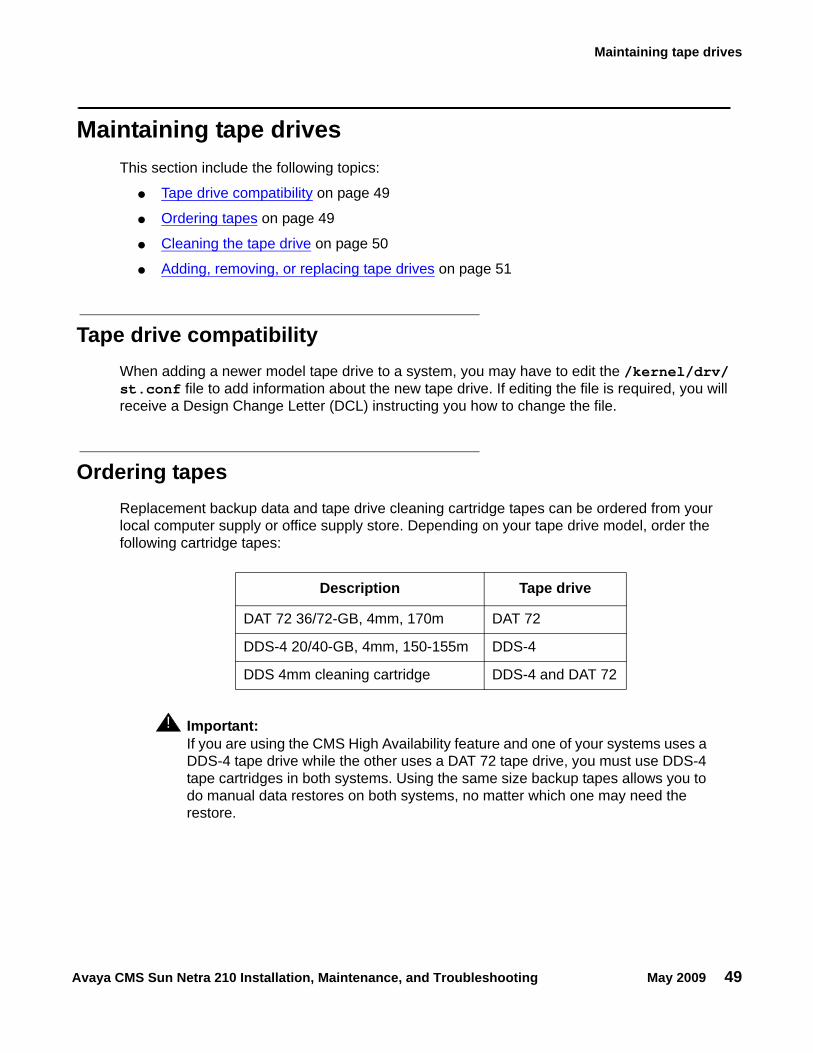
Ordering tapesReplacement backup data and tape drive cleaning cartridge tapes can be ordered from your local computer supply or office supply store. Depending on your tape drive model, order the following cartridge tapes:
! Important:Important: If you are using the CMS High Availability feature and one of your systems uses a
DDS-4 tape drive while the other uses a DAT 72 tape drive, you must use DDS-4 tape cartridges in both systems. Using the same size backup tapes allows you to do manual data restores on both systems, no matter which one may need the restore.
Description Tape drive
DAT 72 36/72-GB, 4mm, 170m DAT 72
DDS-4 20/40-GB, 4mm, 150-155m DDS-4
DDS 4mm cleaning cartridge DDS-4 and DAT 72
Maintenance
50 Avaya CMS Sun Netra 210 Installation, Maintenance, and Troubleshooting May 2009
Cleaning the tape driveThis section describes how you clean the tape drive.
Note:Note: CMS computers do not ship with tape drive cleaning tapes. Avaya recommends
that customers purchase at least one cleaning tape as soon as the computer is installed and in service.
The number of cleaning cycles available on a cleaning cartridge depends on the manufacturer of the cartridge. Regular cleaning is recommended to maximize tape drive performance. Avaya recommends that you clean the tape drive once a week or every five (5) data backups, whichever comes first.
The LEDs on the tape drives will indicate when the tape drives need cleaning. See Tape drive status indicators on page 86. If the Clean LED flashes, either the tape drive heads need cleaning, or the backup tape needs replacing.
To clean the tape drive:
1. Load the cleaning cartridge into the tape drive.
The cleaning cycle begins automatically, and the Tape LED flashes. When the cleaning cycle is complete, the cleaning cartridge is ejected automatically. If the cleaning cartridge does not eject automatically, it may be defective and may need replacing.
2. The first time you use the cleaning cartridge, record the date on the cleaning cartridge. Each time you clean the tape drive, mark an X in the box. After all boxes are filled, replace the cleaning cartridge.
3. Return the cleaning cartridge to the plastic protection box.
If the Clean LED continues to flash, repeat the cleaning procedure using a different cleaning cartridge. If the Clean LED is still flashing, repeat the backup operation with a different tape. If this clears the signal, the first backup tape is nearing the end of its life. Discard the old tape.
Maintaining tape drives
Avaya CMS Sun Netra 210 Installation, Maintenance, and Troubleshooting May 2009 51
Adding, removing, or replacing tape drivesThis section describes how to add, remove, or replace an external tape drive on an existing computer.
Note:Note: External tape drives are pre-installed and required at all times on a computer.
Adding a second tape drive is usually only a temporary measure during the migration process.
Adding or replacing a tape drive
To add or replace a tape drive:
1. Remove any tapes from the tape drive.
2. Log in to the system as root.
3. Enter:
/usr/sbin/shutdown -y -i0 -g0
This shuts down the system and the ok prompt is displayed.
4. Open the front cover.
5. Turn the power switch to the OFF position.
6. Turn off the system monitor.
7. Turn off the tape drive.
8. If replacing a defective tape drive, disconnect the SCSI cables and power cables.
9. Connect the tape drive as shown in Connecting tape drives on page 52.
Maintenance
52 Avaya CMS Sun Netra 210 Installation, Maintenance, and Troubleshooting May 2009
Connecting tape drives
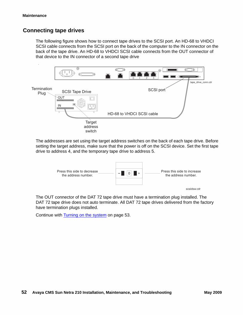
The following figure shows how to connect tape drives to the SCSI port. An HD-68 to VHDCI SCSI cable connects from the SCSI port on the back of the computer to the IN connector on the back of the tape drive. An HD-68 to VHDCI SCSI cable connects from the OUT connector of that device to the IN connector of a second tape drive
.
The addresses are set using the target address switches on the back of each tape drive. Before setting the target address, make sure that the power is off on the SCSI device. Set the first tape drive to address 4, and the temporary tape drive to address 5.
The OUT connector of the DAT 72 tape drive must have a termination plug installed. The DAT 72 tape drive does not auto terminate. All DAT 72 tape drives delivered from the factory have termination plugs installed.
Continue with Turning on the system on page 53.
SCSI port
Targetaddressswitch
tape_drive_conn.cdr
HD-68 to VHDCI SCSI cable
SCSI Tape Drive
IN
OUT
TerminationPlug
0 1 2 3
Press this side to increasethe address number.
Press this side to decreasethe address number.
+
0
scsiidsw.cdr
Maintaining tape drives
Avaya CMS Sun Netra 210 Installation, Maintenance, and Troubleshooting May 2009 53
Turning on the system
To turn on the system:
1. Connect the power cord from the tape drive to a power source.
2. Turn on the tape drives, starting with the tape drive that is farthest from the system and working toward the system.
3. Turn on the system monitor.
4. Open the front cover.
5. Turn the rotary switch to the ON position.
6. Press and release the power button.
POST diagnostics begin.
7. Press Stop+A simultaneously after the console banner is displayed, but before the system starts booting.
The ok prompt is displayed.
8. Enter the following commands:
setenv auto-boot? false
reset-all
This resets the system.
9. Enter:
probe-scsi-all
This checks to see that the system recognizes the new tape drive. The resulting display should list the new drive as Target 4 or Target 5. If the new drive is not listed, make sure there is a secure connection between the SCSI port and the new drive.
10. Reboot the system by entering the following commands:
CAUTION:!
CAUTION: If you fail to enter these commands, any reboots that you do in the future will stop at the boot prompt instead of proceeding through the normal boot-up process.
setenv auto-boot? true
boot -r
The system reboots.
Maintenance
54 Avaya CMS Sun Netra 210 Installation, Maintenance, and Troubleshooting May 2009
Removing the tape drive
To remove the tape drive:
1. Remove any tapes in the tape drive.
2. Log in to the system as root.
3. Enter the following commands:
cd /dev/rmt
pwd
The pwd command verifies that you are in the /dev/rmt directory.
4. Enter:
rm *
This removes SCSI device files. If you do not remove the device files before rebooting the system, the SCSI device files may not match the hardware configuration.
5. Enter:
/usr/sbin/shutdown -y -i0 -g0
This shuts down the system and the ok prompt is displayed.
6. Open the front cover.
7. Turn the power switch to the OFF position.
8. Turn off the system monitor.
9. Turn off all tape drives, starting with the first tape drive.
10. Disconnect the tape drive from the SCSI port or SCSI chain.
11. Turn on all tape drives, starting with the second tape drive.
12. Turn on the system monitor.
13. Open the front cover.
14. Turn the rotary switch to the ON position.
15. Press and release the power button.
POST diagnostics begin.
16. Press Stop+A simultaneously after the console banner is displayed, but before the system starts booting.
The ok prompt is displayed.
Adding memory and replacing the CPU
Avaya CMS Sun Netra 210 Installation, Maintenance, and Troubleshooting May 2009 55
17. Enter the following commands:
setenv auto-boot? false
reset-all
This resets the system.
18. Enter:
probe-scsi-all
The current SCSI devices are displayed. The removed tape drive should not be listed.
19. Reboot the system by entering the following commands:
CAUTION:!
CAUTION: If you fail to enter these commands, any reboots that you do in the future will stop at the boot prompt instead of proceeding through the normal boot-up process.
setenv auto-boot? true
boot -r
The system reboots.
20. Perform a CMSADM file system backup to back up the updated system configuration. See the CMS software installation, maintenance, and troubleshooting document for details.
Adding memory and replacing the CPUMemory and CPU upgrades and repairs can be done by Sun technicians, Avaya technicians, or Avaya business partner technicians. Contact Avaya support or your business partner if your system needs any upgrades or repairs.
Using the System Configuration Card (SCC)The SCC contains the MAC address and Host ID of the Netra 210 computer. Should you ever have to replace the entire unit, you must remove the SCC from the old unit and install it in the new unit. Other than moving the SCC to a new unit, do not remove the SCC from the unit at any time.

Maintenance
56 Avaya CMS Sun Netra 210 Installation, Maintenance, and Troubleshooting May 2009
Avaya CMS Sun Netra 210 Installation, Maintenance, and Troubleshooting May 2009 57
Troubleshooting
This section describes the following troubleshooting procedures:
● Using the remote console on page 58
● Tools on page 65
- Using the prtdiag command on page 66- System messages on page 70- OpenBoot PROM firmware tests on page 71- OpenBoot diagnostic tests on page 77- POST diagnostic messages on page 80- OpenBoot initialization commands on page 81- Diagnosing status indicators on page 82- Sun Validation Test Suite (VTS) on page 87
● Troubleshooting disk drives and the DVD-RW drive on page 88
● Troubleshooting tape drives on page 90
● Recovery procedures on page 93
Additional troubleshooting: See the Sun Netra 210 Service Manual at the Sun documentation Web site for additional troubleshooting procedures:
http://docs.sun.com
Troubleshooting
58 Avaya CMS Sun Netra 210 Installation, Maintenance, and Troubleshooting May 2009
Using the remote consoleIf your system does not boot, or if the system cannot be diagnosed locally, remote support personnel might want to redirect control of the console port from the local console to a dialed-in remote console. Redirecting the console allows support personnel to do remote maintenance as if they were at the local console. You can redirect the console using either:
● The Solaris operating system
● OpenBoot diagnostics
This section consists of the following procedures:
● Redirecting the console using Solaris on page 58. Use this procedure when the system will boot up to the Solaris operating system.
● Redirecting the console using OpenBoot mode on page 61. Use this procedure when the system will not boot up to the Solaris operating system.
Redirecting the console using SolarisThis procedure describes how to use the Solaris operating system to redirect the local console to the serial port. This procedure is usually done from the remote console that has dialed in to the system. Should you encounter any problems setting up the remote console, see Remote console port problems on page 96 for troubleshooting procedures.
CAUTION:!
CAUTION: Use this procedure only when absolutely necessary. If the console redirects and the modem line drops, you may not be able to get back into the system.
Redirecting the local console to the remote console
To redirect control of the console port from the local console to a dialed-in remote console:
1. Dial in from the remote console to the remote console modem, and log in as root.
2. At the remote console, enter:
/cms/install/bin/abcadm -r ttyb
The following message is displayed at the remote console:
ttyb is currently set to be incomingAre you sure you want to change it? [y,n,?]
Using the remote console
Avaya CMS Sun Netra 210 Installation, Maintenance, and Troubleshooting May 2009 59
3. At the remote console, enter: y
The following message is displayed at the remote console:
4. At the remote console, enter:
/cms/install/bin/abcadm -c -b 9600 ttyb
The following message is displayed at the remote console:
5. At the remote console, enter: y
The following message is displayed at the remote console:
The following occurs:
● The system begins to shut down.
● Shutdown, reset, and reboot messages are displayed on the local console.
● When the system starts to come back up, the local console goes blank.
● The system boot diagnostics are displayed on the remote console.
● After the system reboots, a console login: prompt is displayed on the remote console.
6. Log in to the remote console as root.
ttyb administration removed
This change requires a reboot to take affectAre you ready to reboot? [y,n,?]
donedesktop auto-start disabledProceeding to reboot.
Troubleshooting
60 Avaya CMS Sun Netra 210 Installation, Maintenance, and Troubleshooting May 2009
Redirecting the remote console back to the local console
CAUTION:!
CAUTION: Do not enter Ctrl+D from the remote console to exit the system without first redirecting control back to the local console. If you do, you may lock yourself from using the console locally or remotely.
To redirect control of the console port from the remote console back to the local console:
1. At the remote console, enter:
/cms/install/bin/abcadm -c local
The following message is displayed at the remote console:
2. At the remote console, enter: y
The following occurs:
● The system begins to shut down.
● Shutdown, reset, and reboot messages are displayed on the local console.
● When the system starts to come back up, the system boot diagnostics are displayed on the local console.
● After the system reboots, the console login: prompt is displayed on the remote console.
● The login screen is displayed on the local console.
3. Log in to the local console as root.
4. Log in to the remote console as root.
Control of the console port is redirected from the remote console back to the local console.
Console set to local
This change requires a reboot to take affect
Are you ready to reboot? [y,n,?]
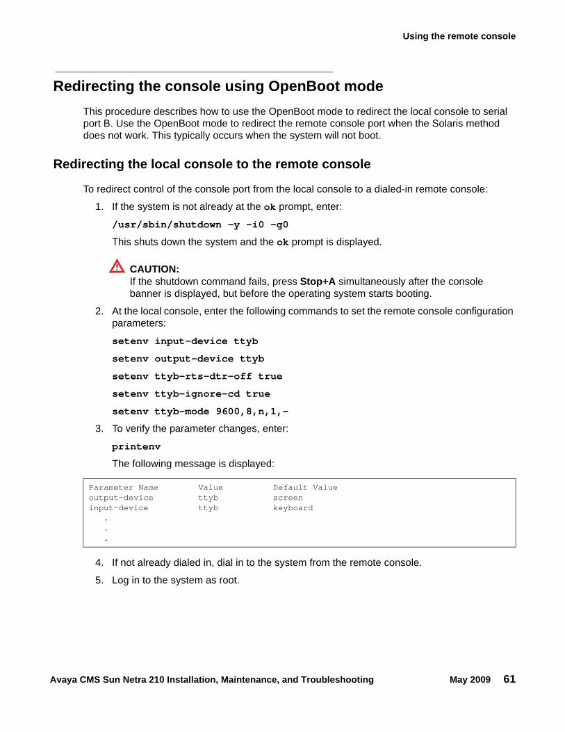
Using the remote console
Avaya CMS Sun Netra 210 Installation, Maintenance, and Troubleshooting May 2009 61
Redirecting the console using OpenBoot modeThis procedure describes how to use the OpenBoot mode to redirect the local console to serial port B. Use the OpenBoot mode to redirect the remote console port when the Solaris method does not work. This typically occurs when the system will not boot.
Redirecting the local console to the remote console
To redirect control of the console port from the local console to a dialed-in remote console:
1. If the system is not already at the ok prompt, enter:
/usr/sbin/shutdown -y -i0 -g0
This shuts down the system and the ok prompt is displayed.
CAUTION:!
CAUTION: If the shutdown command fails, press Stop+A simultaneously after the console banner is displayed, but before the operating system starts booting.
2. At the local console, enter the following commands to set the remote console configuration parameters:
setenv input-device ttyb
setenv output-device ttyb
setenv ttyb-rts-dtr-off true
setenv ttyb-ignore-cd true
setenv ttyb-mode 9600,8,n,1,-
3. To verify the parameter changes, enter:
printenv
The following message is displayed:
4. If not already dialed in, dial in to the system from the remote console.
5. Log in to the system as root.
Parameter Name Value Default Valueoutput-device ttyb screeninput-device ttyb keyboard
.
.
.
Troubleshooting
62 Avaya CMS Sun Netra 210 Installation, Maintenance, and Troubleshooting May 2009
6. At the local console, enter:
boot
The following occurs:
● The system begins to shut down.
● Shutdown, reset, and reboot messages are displayed on the local console.
● When the system starts to come back up, the local console goes blank.
● The system boot diagnostics are displayed on the remote console.
● After the system reboots, a console login: prompt is displayed on the remote console.
7. Log in to the remote console as root.
Redirecting the remote console back to the local console
CAUTION:!
CAUTION: Do not enter Ctrl+D from the remote console to exit the system without first redirecting control back to the local console. If you do, you may lock yourself from using the console locally or remotely.
Using OpenBoot mode, there are two ways to redirect control of the console port from the remote console back to the local console:
● Method 1: from the remote console on page 63 (recommended)
● Method 2: from the local site on page 64 (not recommended)
Using the remote console
Avaya CMS Sun Netra 210 Installation, Maintenance, and Troubleshooting May 2009 63
Method 1: from the remote console : To redirect control of the console port from the remote console back to the local console:
1. Do one of the following:
● If the system is in UNIX, enter the following commands at the remote console:
eeprom output-device=screen
eeprom input-device=keyboard
eeprom ttyb-rts-dtr-off=true
eeprom ttyb-ignore-cd=false
/usr/sbin/shutdown -y -i6 -g0
● If the system is in OpenBoot mode, enter the following commands at the remote console:
setenv output-device screen
setenv input-device keyboard
setenv ttyb-rts-dtr-off true
setenv ttyb-ignore-cd false
reset
The following occurs:
● The system begins to shut down.
● Shutdown, reset, and reboot messages are displayed on the remote console.
● When the system starts to come back up, the system boot diagnostics are displayed on the local console.
● The login screen is displayed on the local console.
2. At the remote console, hang up the modem connection.
3. Log in to the system as root at the local console.
4. To see what is on the ttyb port, enter:
/cms/install/bin/abcadm -k
5. To start a port monitor on ttyb, enter:
/cms/install/bin/abcadm -i -b 9600 ttyb
Troubleshooting
64 Avaya CMS Sun Netra 210 Installation, Maintenance, and Troubleshooting May 2009
Method 2: from the local site: The onsite technician will use this procedure from the local site. Use this method only when Method 1 will not work.
CAUTION:!
CAUTION: This method of redirecting the console port should be done only as a last resort. This procedure resets the NVRAM defaults to the Sun factory settings.
To redirect control of the console port from the remote console back to the local console:
1. Turn the power off and back on for the computer.
2. As the computer begins to boot up, double-click the power switch on the front of the system.
The prompt is displayed on the local console.
3. At the ok prompt, enter:
boot
4. When the system boots up, log in to the system as root at the local console.
5. To see what is on the ttyb port, enter:
/cms/install/bin/abcadm -k
6. To start a port monitor on ttyb, enter:
/cms/install/bin/abcadm -i -b 9600 ttyb
The following message is displayed:
ttyb set to incoming port 9600 baud
Tools
Avaya CMS Sun Netra 210 Installation, Maintenance, and Troubleshooting May 2009 65
ToolsThere are several tools available to help diagnose hardware problems:
● Using the prtdiag command on page 66
● System messages on page 70
● OpenBoot PROM firmware tests on page 71
● OpenBoot diagnostic tests on page 77
● POST diagnostic messages on page 80
● OpenBoot initialization commands on page 81
● Diagnosing status indicators on page 82
● Sun Validation Test Suite (VTS) on page 87
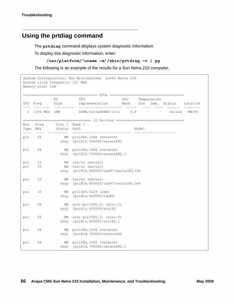
Troubleshooting
66 Avaya CMS Sun Netra 210 Installation, Maintenance, and Troubleshooting May 2009
Using the prtdiag commandThe prtdiag command displays system diagnostic information.
To display this diagnostic information, enter:
/usr/platform/‘uname -m‘/sbin/prtdiag -v | pg
The following is an example of the results for a Sun Netra 210 computer.
System Configuration: Sun Microsystems sun4u Netra 210System clock frequency: 167 MHZMemory size: 1GB
==================================== CPUs ==================================== E$ CPU CPU TemperatureCPU Freq Size Implementation Mask Die Amb. Status Location--- -------- ---------- --------------------- ----- ---- ---- ------ -------- 0 1336 MHz 1MB SUNW,UltraSPARC-IIIi 3.4 - - online MB/P0
================================= IO Devices =================================Bus Freq Slot + Name +Type MHz Status Path Model---- ---- ---------- ---------------------------- --------------------pci 66 MB pci108e,1648 (network) okay /pci@1f,700000/network@2
pci 66 MB pci108e,1648 (network) okay /pci@1f,700000/network@2,1
pci 33 MB isa/su (serial)pci 33 MB isa/su (serial) okay /pci@1e,600000/isa@7/serial@0,3f8
pci 33 MB isa/su (serial) okay /pci@1e,600000/isa@7/serial@0,2e8
pci 33 MB pci10b9,5229 (ide) okay /pci@1e,600000/ide@d
pci 66 MB scsi-pci1000,21 (scsi-2) okay /pci@1c,600000/scsi@2
pci 66 MB scsi-pci1000,21 (scsi-2) okay /pci@1c,600000/scsi@2,1
pci 66 MB pci108e,1648 (network) okay /pci@1d,700000/network@2
pci 66 MB pci108e,1648 (network) okay /pci@1d,700000/network@2,1
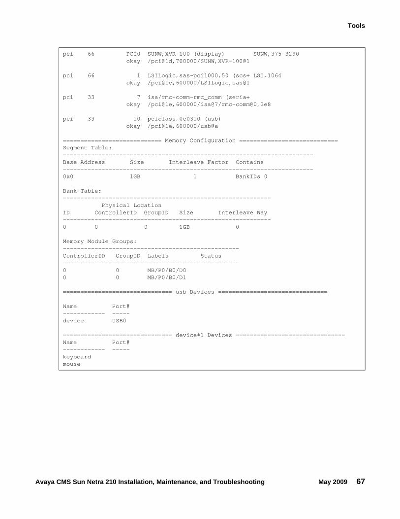
Tools
Avaya CMS Sun Netra 210 Installation, Maintenance, and Troubleshooting May 2009 67
pci 66 PCI0 SUNW,XVR-100 (display) SUNW,375-3290 okay /pci@1d,700000/SUNW,XVR-100@1
pci 66 1 LSILogic,sas-pci1000,50 (scs+ LSI,1064 okay /pci@1c,600000/LSILogic,sas@1
pci 33 7 isa/rmc-comm-rmc_comm (seria+ okay /pci@1e,600000/isa@7/rmc-comm@0,3e8
pci 33 10 pciclass,0c0310 (usb) okay /pci@1e,600000/usb@a
============================ Memory Configuration ============================Segment Table:-----------------------------------------------------------------------Base Address Size Interleave Factor Contains-----------------------------------------------------------------------0x0 1GB 1 BankIDs 0
Bank Table:----------------------------------------------------------- Physical LocationID ControllerID GroupID Size Interleave Way-----------------------------------------------------------0 0 0 1GB 0
Memory Module Groups:--------------------------------------------------ControllerID GroupID Labels Status--------------------------------------------------0 0 MB/P0/B0/D00 0 MB/P0/B0/D1
=============================== usb Devices ===============================
Name Port#------------ -----device USB0
=============================== device#1 Devices ===============================Name Port#------------ -----keyboardmouse
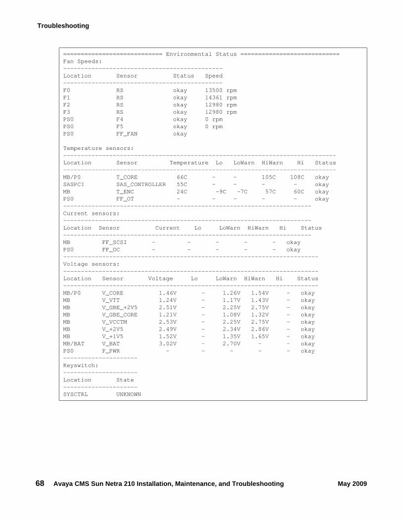
Troubleshooting
68 Avaya CMS Sun Netra 210 Installation, Maintenance, and Troubleshooting May 2009
============================ Environmental Status ============================Fan Speeds:---------------------------------------------Location Sensor Status Speed---------------------------------------------F0 RS okay 13500 rpmF1 RS okay 14361 rpmF2 RS okay 12980 rpmF3 RS okay 12980 rpmPS0 F4 okay 0 rpmPS0 F5 okay 0 rpmPS0 FF_FAN okay
Temperature sensors:-----------------------------------------------------------------------------Location Sensor Temperature Lo LoWarn HiWarn Hi Status-----------------------------------------------------------------------------MB/P0 T_CORE 66C - - 105C 108C okaySASPCI SAS_CONTROLLER 55C - - - - okayMB T_ENC 24C -9C -7C 57C 60C okayPS0 FF_OT - - - - - okay----------------------------------------------------------------------Current sensors:----------------------------------------------------------------------Location Sensor Current Lo LoWarn HiWarn Hi Status----------------------------------------------------------------------MB FF_SCSI - - - - - okayPS0 FF_OC - - - - - okay------------------------------------------------------------------------Voltage sensors:------------------------------------------------------------------------Location Sensor Voltage Lo LoWarn HiWarn Hi Status------------------------------------------------------------------------MB/P0 V_CORE 1.46V - 1.26V 1.54V - okayMB V_VTT 1.24V - 1.17V 1.43V - okayMB V_GBE_+2V5 2.51V - 2.25V 2.75V - okayMB V_GBE_CORE 1.21V - 1.08V 1.32V - okayMB V_VCCTM 2.53V - 2.25V 2.75V - okayMB V_+2V5 2.49V - 2.34V 2.86V - okayMB V_+1V5 1.52V - 1.35V 1.65V - okayMB/BAT V_BAT 3.02V - 2.70V - - okayPS0 P_PWR - - - - - okay---------------------Keyswitch:---------------------Location State---------------------SYSCTRL UNKNOWN
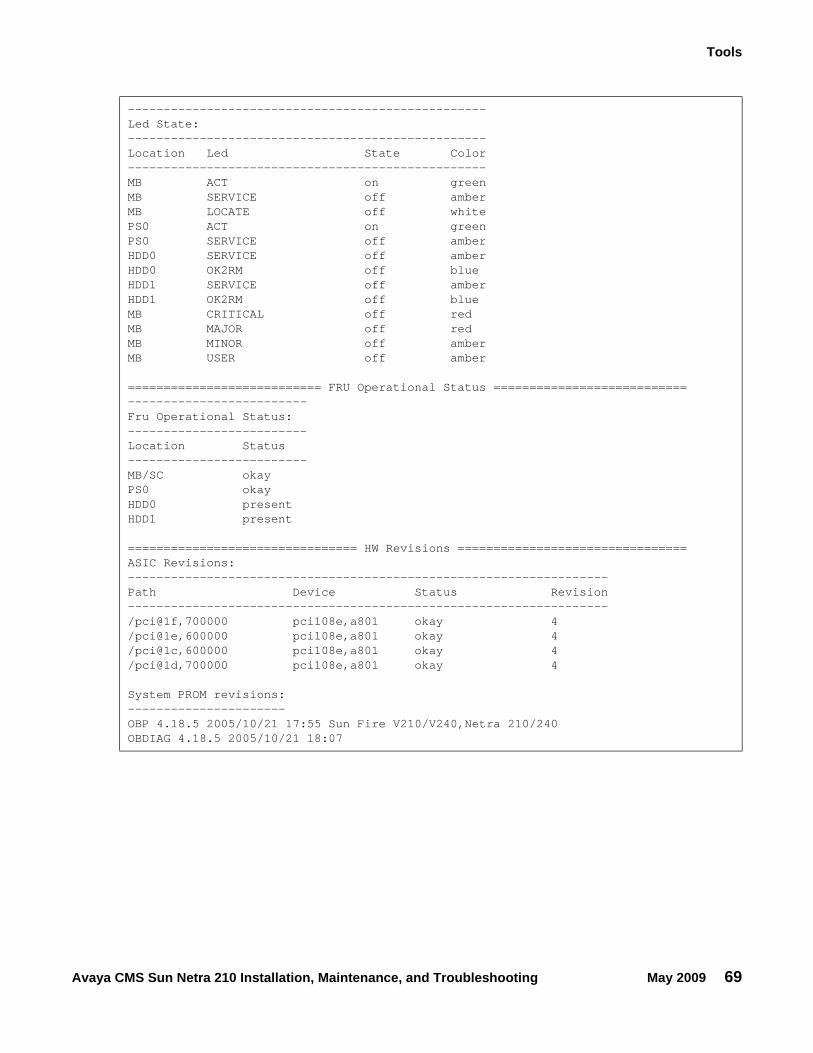
Tools
Avaya CMS Sun Netra 210 Installation, Maintenance, and Troubleshooting May 2009 69
--------------------------------------------------Led State:--------------------------------------------------Location Led State Color--------------------------------------------------MB ACT on greenMB SERVICE off amberMB LOCATE off whitePS0 ACT on greenPS0 SERVICE off amberHDD0 SERVICE off amberHDD0 OK2RM off blueHDD1 SERVICE off amberHDD1 OK2RM off blueMB CRITICAL off redMB MAJOR off redMB MINOR off amberMB USER off amber
=========================== FRU Operational Status ===========================-------------------------Fru Operational Status:-------------------------Location Status-------------------------MB/SC okayPS0 okayHDD0 presentHDD1 present
================================ HW Revisions ================================ASIC Revisions:-------------------------------------------------------------------Path Device Status Revision-------------------------------------------------------------------/pci@1f,700000 pci108e,a801 okay 4/pci@1e,600000 pci108e,a801 okay 4/pci@1c,600000 pci108e,a801 okay 4/pci@1d,700000 pci108e,a801 okay 4
System PROM revisions:----------------------OBP 4.18.5 2005/10/21 17:55 Sun Fire V210/V240,Netra 210/240OBDIAG 4.18.5 2005/10/21 18:07
Troubleshooting
70 Avaya CMS Sun Netra 210 Installation, Maintenance, and Troubleshooting May 2009
System messagesSystem messages can alert you to system problems, such as a device that is about to fail. By default, many of the messages are displayed on the system console and are stored in /var/adm.
You can display system messages with the dmesg command. Here are some factors to keep in mind:
● A list of the most recent messages is displayed.
● The /var/adm directory contains several message files. The most recent messages are in /var/adm/messages and in /var/adm/messages.0. The oldest are in /var/adm/messages.3.
● Periodically, a new file is created, and the /var/adm/messages.3 file is deleted, /var/adm/messages.2 is renamed /var/adm/messages.3, /var/adm/messages.1 is renamed /var/adm/messages.2, and /var/adm/messages.0 is renamed /var/adm/messages.1.
The message files may contain not only system messages, but also core dumps and other data, which can cause /var/adm to grow quite large. To keep the directory to a reasonable size and ensure that future core dumps can be saved, you should remove unneeded files periodically. You can automate the task by using crontab. See your Sun system documentation for information on crontab.
Tools
Avaya CMS Sun Netra 210 Installation, Maintenance, and Troubleshooting May 2009 71
OpenBoot PROM firmware testsThe OpenBoot PROM (OBP) on-board firmware performs a routine set of firmware and hardware tests.
Note:Note: Different versions of Solaris have different versions of the OpenBoot commands.
Not all commands are available with every version.
This section includes the following topics:
● Using the OpenBoot PROM tests on page 71
● Test descriptions on page 72
● Probing IDE devices on page 73
● Probing SCSI devices on page 74
Using the OpenBoot PROM tests
To use the OpenBoot PROM tests:
1. From the root login, turn off CMS.
2. Enter:
/usr/sbin/shutdown -y -i0 -g0
This shuts down the system and the ok prompt is displayed.
3. At the ok prompt, enter the following commands:
setenv auto-boot? false
reset-all
The system resets and the ok prompt is displayed.
4. Use the commands that are shown in Test descriptions on page 72.
5. When you finish testing, enter the following commands:
CAUTION:!
CAUTION: If you fail to enter these commands, any reboots that you do in the future will stop at the boot prompt instead of proceeding through the normal boot-up process.
setenv auto-boot? true
boot
The system reboots.
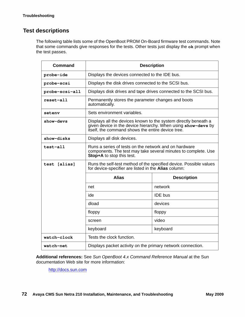
Troubleshooting
72 Avaya CMS Sun Netra 210 Installation, Maintenance, and Troubleshooting May 2009
Test descriptions
The following table lists some of the OpenBoot PROM On-Board firmware test commands. Note that some commands give responses for the tests. Other tests just display the ok prompt when the test passes.
Additional references: See Sun OpenBoot 4.x Command Reference Manual at the Sun documentation Web site for more information:
http://docs.sun.com
Command Description
probe-ide Displays the devices connected to the IDE bus.
probe-scsi Displays the disk drives connected to the SCSI bus.
probe-scsi-all Displays disk drives and tape drives connected to the SCSI bus.
reset-all Permanently stores the parameter changes and boots automatically.
setenv Sets environment variables.
show-devs Displays all the devices known to the system directly beneath a given device in the device hierarchy. When using show-devs by itself, the command shows the entire device tree.
show-disks Displays all disk devices.
test-all Runs a series of tests on the network and on hardware components. The test may take several minutes to complete. Use Stop+A to stop this test.
test [alias] Runs the self-test method of the specified device. Possible values for device-specifier are listed in the Alias column:
Alias Description
net network
ide IDE bus
dload devices
floppy floppy
screen video
keyboard keyboard
watch-clock Tests the clock function.
watch-net Displays packet activity on the primary network connection.
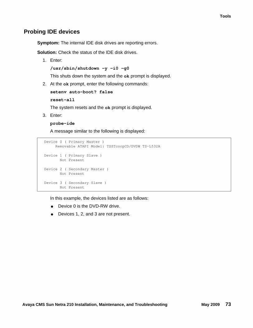
Tools
Avaya CMS Sun Netra 210 Installation, Maintenance, and Troubleshooting May 2009 73
Probing IDE devices
Symptom: The internal IDE disk drives are reporting errors.
Solution: Check the status of the IDE disk drives.
1. Enter:
/usr/sbin/shutdown -y -i0 -g0
This shuts down the system and the ok prompt is displayed.
2. At the ok prompt, enter the following commands:
setenv auto-boot? false
reset-all
The system resets and the ok prompt is displayed.
3. Enter:
probe-ide
A message similar to the following is displayed:
In this example, the devices listed are as follows:
● Device 0 is the DVD-RW drive.
● Devices 1, 2, and 3 are not present.
Device 0 ( Primary Master )Removable ATAPI Model: TSSTcorpCD/DVDW TS-L532A
Device 1 ( Primary Slave )Not Present
Device 2 ( Secondary Master )Not Present
Device 3 ( Secondary Slave )Not Present
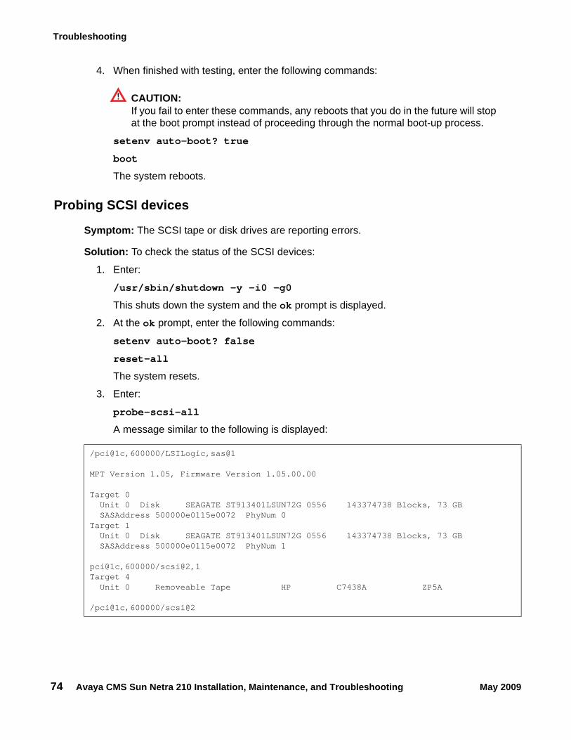
Troubleshooting
74 Avaya CMS Sun Netra 210 Installation, Maintenance, and Troubleshooting May 2009
4. When finished with testing, enter the following commands:
CAUTION:!
CAUTION: If you fail to enter these commands, any reboots that you do in the future will stop at the boot prompt instead of proceeding through the normal boot-up process.
setenv auto-boot? true
boot
The system reboots.
Probing SCSI devices
Symptom: The SCSI tape or disk drives are reporting errors.
Solution: To check the status of the SCSI devices:
1. Enter:
/usr/sbin/shutdown -y -i0 -g0
This shuts down the system and the ok prompt is displayed.
2. At the ok prompt, enter the following commands:
setenv auto-boot? false
reset-all
The system resets.
3. Enter:
probe-scsi-all
A message similar to the following is displayed:
/pci@1c,600000/LSILogic,sas@1
MPT Version 1.05, Firmware Version 1.05.00.00
Target 0Unit 0 Disk SEAGATE ST913401LSUN72G 0556 143374738 Blocks, 73 GBSASAddress 500000e0115e0072 PhyNum 0
Target 1Unit 0 Disk SEAGATE ST913401LSUN72G 0556 143374738 Blocks, 73 GBSASAddress 500000e0115e0072 PhyNum 1
pci@1c,600000/scsi@2,1Target 4
Unit 0 Removeable Tape HP C7438A ZP5A
/pci@1c,600000/scsi@2
Tools
Avaya CMS Sun Netra 210 Installation, Maintenance, and Troubleshooting May 2009 75
In this example, the devices listed are as follows:
● Target 0 is the primary disk drive.
● Target 1 is the secondary (mirror) disk drive.
● Target 4 is the external tape drive.
Note:Note: The actual devices listed depends on the devices installed on the SCSI bus.
4. If there are drives other than what was shown in the message, shut down the system and check the drive cabling.
5. When finished with testing, enter the following commands:
CAUTION:!
CAUTION: If you fail to enter these commands, any reboots that you do in the future will stop at the boot prompt instead of proceeding through the normal boot-up process.
setenv auto-boot? true
boot
The system reboots.
Symptom: The SCSI tape or disk drives are reporting errors.
Solution: The system might have duplicate SCSI target addresses on one bus.
Note:Note: Two targets may have the same target number if they are on different SCSI
busses.
To check for duplicate SCSI target addresses:
1. Unplug all but one of the disks.
2. Enter:
probe-scsi-all
Record the target number and its corresponding unit number.
3. Plug in another disk, and perform Step 2 again.
4. If you get an error message, change the target number of this disk to one of the unused target numbers.
Troubleshooting
76 Avaya CMS Sun Netra 210 Installation, Maintenance, and Troubleshooting May 2009
5. When you finish testing, enter the following commands:
CAUTION:!
CAUTION: If you fail to enter these commands, any reboots that you do in the future will stop at the boot prompt instead of proceeding through the normal boot-up process.
setenv auto-boot? true
boot
The system reboots.
Tools
Avaya CMS Sun Netra 210 Installation, Maintenance, and Troubleshooting May 2009 77
OpenBoot diagnostic testsOpenBoot Diagnostics (OBDiag) is a menu-driven tool that diagnoses system hardware. OBDiag performs root-cause failure analysis on the referenced devices by testing internal registers, confirming subsystem integrity, and verifying device functionality.
To use the OpenBoot diagnostic tests:
1. From the root login, turn off CMS.
2. Enter:
/usr/sbin/shutdown -y -i0 -g0
The system shuts down and the ok prompt is displayed.
3. Set the rotary switch to the diagnostics position.
4. At the ok prompt, enter the following commands:
setenv auto-boot? false
reset-all
The system resets.
5. Enter:
obdiag
This loads the test program and the test menu is displayed.
6. Enter:
test <command number>
See Test descriptions on page 78 for a description of each command.
7. When finished with testing, set the key switch to the normal position.
8. Enter the following commands:
CAUTION:!
CAUTION: If you fail to enter these commands, any reboots that you do in the future will stop at the boot prompt instead of proceeding through the normal boot-up process.
setenv auto-boot? true
boot
The system reboots.
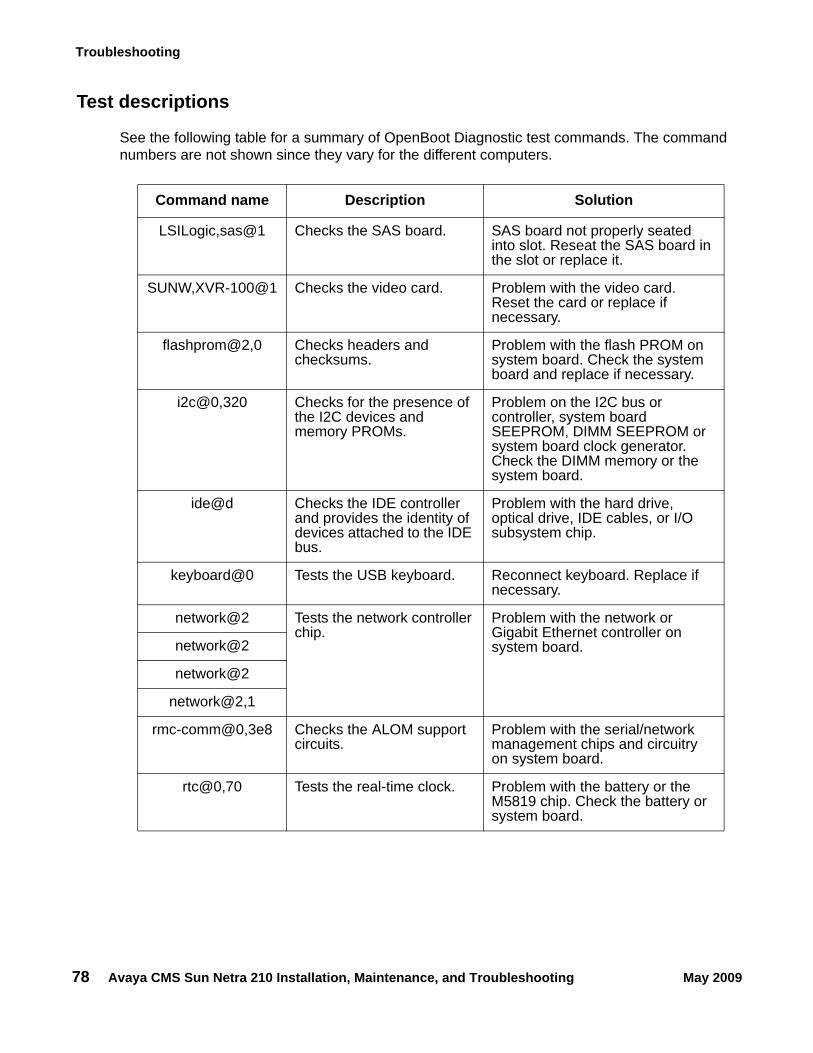
Troubleshooting
78 Avaya CMS Sun Netra 210 Installation, Maintenance, and Troubleshooting May 2009
Test descriptions
See the following table for a summary of OpenBoot Diagnostic test commands. The command numbers are not shown since they vary for the different computers.
Command name Description Solution
LSILogic,sas@1 Checks the SAS board. SAS board not properly seated into slot. Reseat the SAS board in the slot or replace it.
SUNW,XVR-100@1 Checks the video card. Problem with the video card. Reset the card or replace if necessary.
flashprom@2,0 Checks headers and checksums.
Problem with the flash PROM on system board. Check the system board and replace if necessary.
i2c@0,320 Checks for the presence of the I2C devices and memory PROMs.
Problem on the I2C bus or controller, system board SEEPROM, DIMM SEEPROM or system board clock generator. Check the DIMM memory or the system board.
ide@d Checks the IDE controller and provides the identity of devices attached to the IDE bus.
Problem with the hard drive, optical drive, IDE cables, or I/O subsystem chip.
keyboard@0 Tests the USB keyboard. Reconnect keyboard. Replace if necessary.
network@2 Tests the network controller chip.
Problem with the network or Gigabit Ethernet controller on system board.network@2
network@2
network@2,1
rmc-comm@0,3e8 Checks the ALOM support circuits.
Problem with the serial/network management chips and circuitry on system board.
rtc@0,70 Tests the real-time clock. Problem with the battery or the M5819 chip. Check the battery or system board.
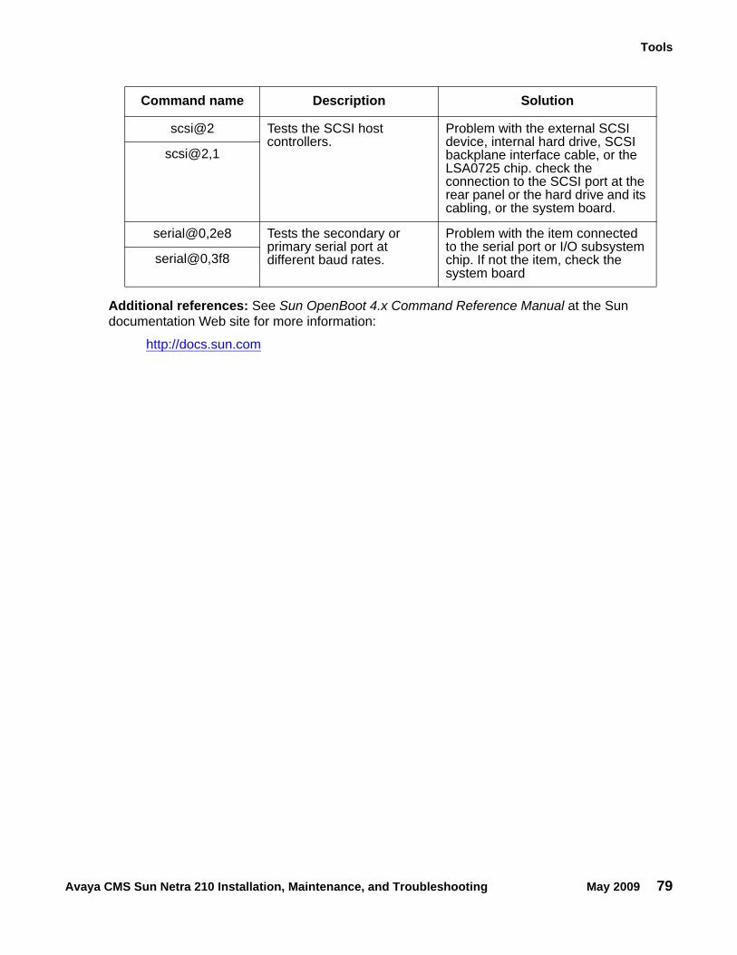
Tools
Avaya CMS Sun Netra 210 Installation, Maintenance, and Troubleshooting May 2009 79
Additional references: See Sun OpenBoot 4.x Command Reference Manual at the Sun documentation Web site for more information:
http://docs.sun.com
scsi@2 Tests the SCSI host controllers.
Problem with the external SCSI device, internal hard drive, SCSI backplane interface cable, or the LSA0725 chip. check the connection to the SCSI port at the rear panel or the hard drive and its cabling, or the system board.
scsi@2,1
serial@0,2e8 Tests the secondary or primary serial port at different baud rates.
Problem with the item connected to the serial port or I/O subsystem chip. If not the item, check the system board
serial@0,3f8
Command name Description Solution
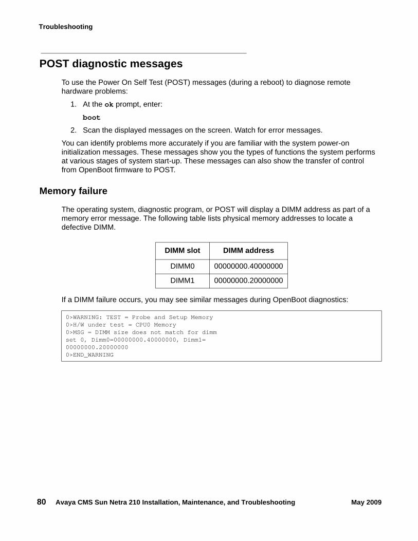
Troubleshooting
80 Avaya CMS Sun Netra 210 Installation, Maintenance, and Troubleshooting May 2009
POST diagnostic messagesTo use the Power On Self Test (POST) messages (during a reboot) to diagnose remote hardware problems:
1. At the ok prompt, enter:
boot
2. Scan the displayed messages on the screen. Watch for error messages.
You can identify problems more accurately if you are familiar with the system power-on initialization messages. These messages show you the types of functions the system performs at various stages of system start-up. These messages can also show the transfer of control from OpenBoot firmware to POST.
Memory failure
The operating system, diagnostic program, or POST will display a DIMM address as part of a memory error message. The following table lists physical memory addresses to locate a defective DIMM.
If a DIMM failure occurs, you may see similar messages during OpenBoot diagnostics:
DIMM slot DIMM address
DIMM0 00000000.40000000
DIMM1 00000000.20000000
0>WARNING: TEST = Probe and Setup Memory0>H/W under test = CPU0 Memory0>MSG = DIMM size does not match for dimmset 0, Dimm0=00000000.40000000, Dimm1=00000000.200000000>END_WARNING
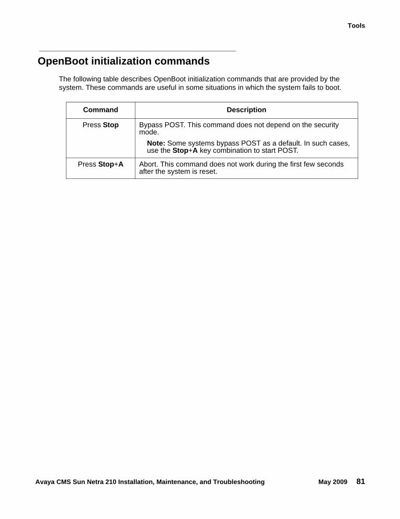
Tools
Avaya CMS Sun Netra 210 Installation, Maintenance, and Troubleshooting May 2009 81
OpenBoot initialization commandsThe following table describes OpenBoot initialization commands that are provided by the system. These commands are useful in some situations in which the system fails to boot.
Command Description
Press Stop Bypass POST. This command does not depend on the security mode.
Note: Some systems bypass POST as a default. In such cases, use the Stop+A key combination to start POST.
Press Stop+A Abort. This command does not work during the first few seconds after the system is reset.
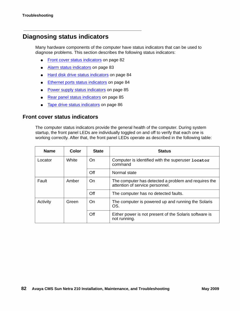
Troubleshooting
82 Avaya CMS Sun Netra 210 Installation, Maintenance, and Troubleshooting May 2009
Diagnosing status indicatorsMany hardware components of the computer have status indicators that can be used to diagnose problems. This section describes the following status indicators:
● Front cover status indicators on page 82
● Alarm status indicators on page 83
● Hard disk drive status indicators on page 84
● Ethernet ports status indicators on page 84
● Power supply status indicators on page 85
● Rear panel status indicators on page 85
● Tape drive status indicators on page 86
Front cover status indicators
The computer status indicators provide the general health of the computer. During system startup, the front panel LEDs are individually toggled on and off to verify that each one is working correctly. After that, the front panel LEDs operate as described in the following table:
Name Color State Status
Locator White On Computer is identified with the superuser locator command
Off Normal state
Fault Amber On The computer has detected a problem and requires the attention of service personnel.
Off The computer has no detected faults.
Activity Green On The computer is powered up and running the Solaris OS.
Off Either power is not present of the Solaris software is not running.
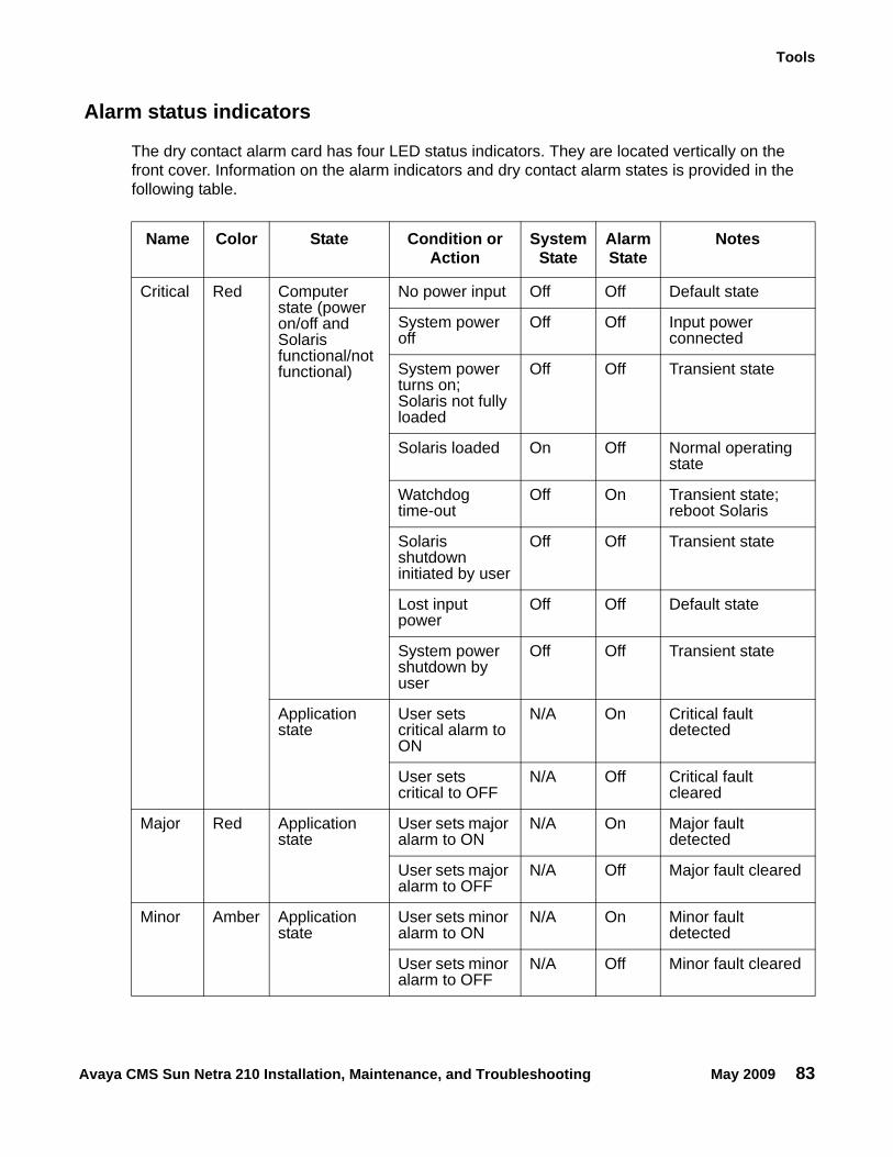
Tools
Avaya CMS Sun Netra 210 Installation, Maintenance, and Troubleshooting May 2009 83
Alarm status indicators
The dry contact alarm card has four LED status indicators. They are located vertically on the front cover. Information on the alarm indicators and dry contact alarm states is provided in the following table.
Name Color State Condition or Action
System State
Alarm State
Notes
Critical Red Computer state (power on/off and Solaris functional/not functional)
No power input Off Off Default state
System power off
Off Off Input power connected
System power turns on; Solaris not fully loaded
Off Off Transient state
Solaris loaded On Off Normal operating state
Watchdog time-out
Off On Transient state; reboot Solaris
Solaris shutdown initiated by user
Off Off Transient state
Lost input power
Off Off Default state
System power shutdown by user
Off Off Transient state
Application state
User sets critical alarm to ON
N/A On Critical fault detected
User sets critical to OFF
N/A Off Critical fault cleared
Major Red Application state
User sets major alarm to ON
N/A On Major fault detected
User sets major alarm to OFF
N/A Off Major fault cleared
Minor Amber Application state
User sets minor alarm to ON
N/A On Minor fault detected
User sets minor alarm to OFF
N/A Off Minor fault cleared
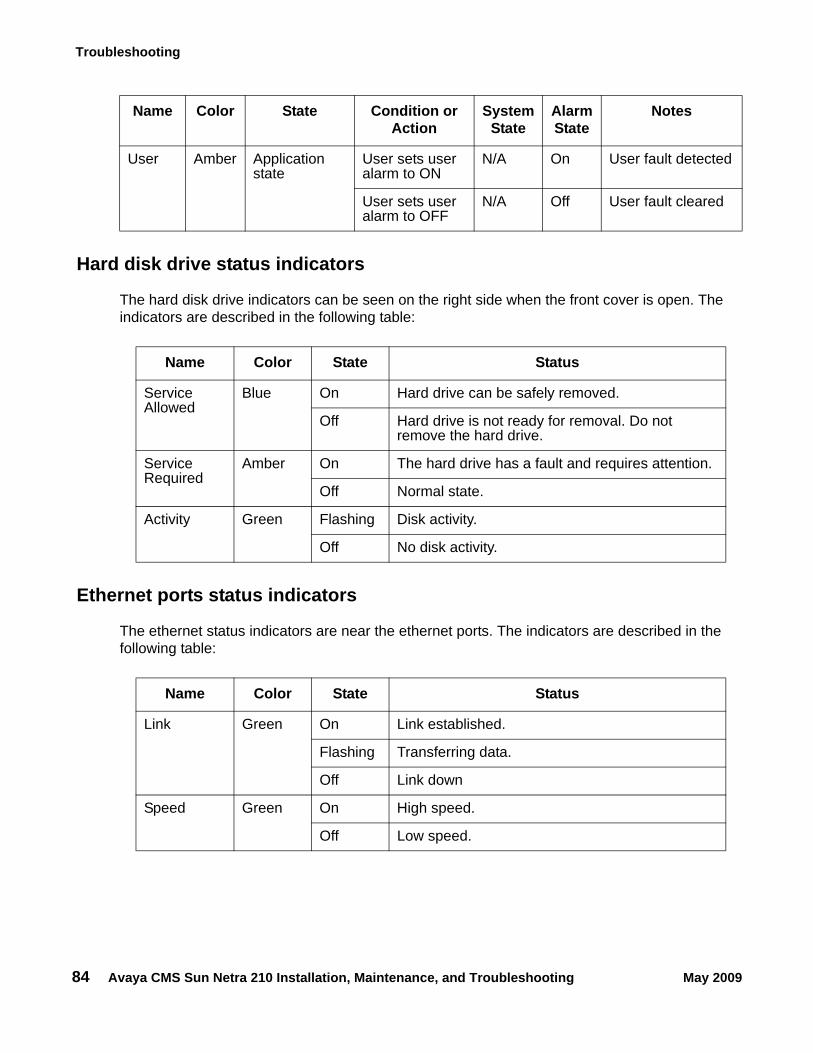
Troubleshooting
84 Avaya CMS Sun Netra 210 Installation, Maintenance, and Troubleshooting May 2009
Hard disk drive status indicators
The hard disk drive indicators can be seen on the right side when the front cover is open. The indicators are described in the following table:
Ethernet ports status indicators
The ethernet status indicators are near the ethernet ports. The indicators are described in the following table:
User Amber Application state
User sets user alarm to ON
N/A On User fault detected
User sets user alarm to OFF
N/A Off User fault cleared
Name Color State Condition or Action
System State
Alarm State
Notes
Name Color State Status
Service Allowed
Blue On Hard drive can be safely removed.
Off Hard drive is not ready for removal. Do not remove the hard drive.
Service Required
Amber On The hard drive has a fault and requires attention.
Off Normal state.
Activity Green Flashing Disk activity.
Off No disk activity.
Name Color State Status
Link Green On Link established.
Flashing Transferring data.
Off Link down
Speed Green On High speed.
Off Low speed.
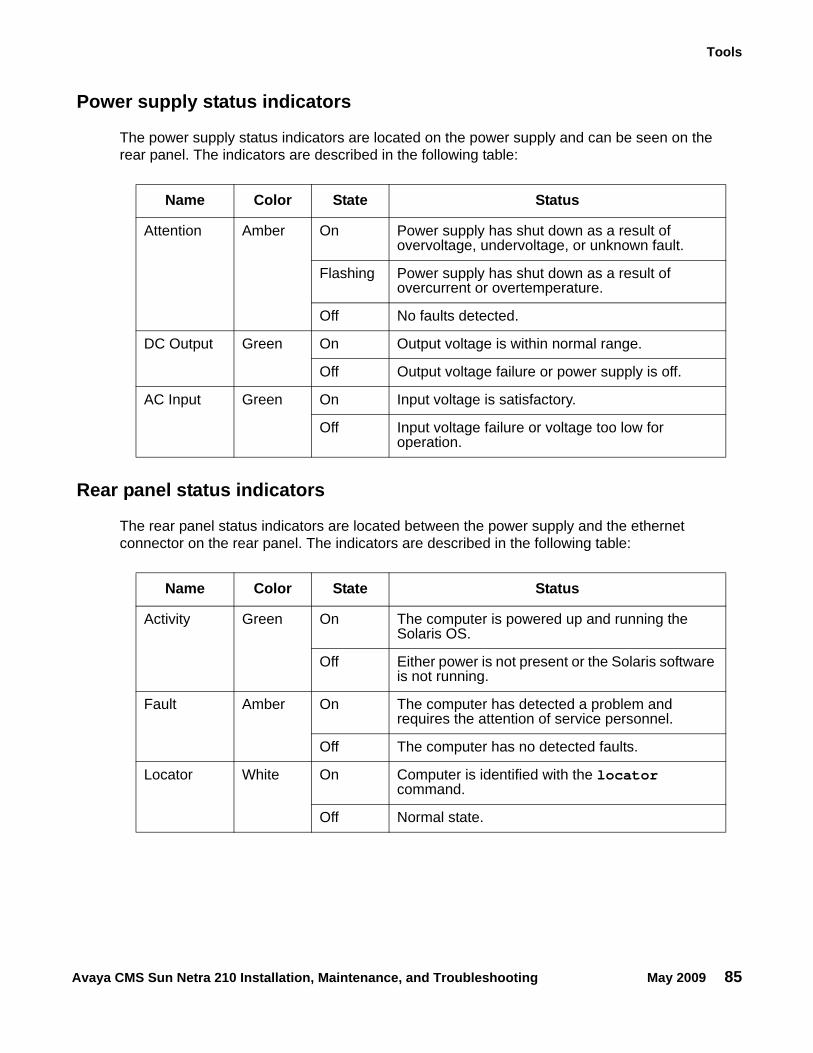
Tools
Avaya CMS Sun Netra 210 Installation, Maintenance, and Troubleshooting May 2009 85
Power supply status indicators
The power supply status indicators are located on the power supply and can be seen on the rear panel. The indicators are described in the following table:
Rear panel status indicators
The rear panel status indicators are located between the power supply and the ethernet connector on the rear panel. The indicators are described in the following table:
Name Color State Status
Attention Amber On Power supply has shut down as a result of overvoltage, undervoltage, or unknown fault.
Flashing Power supply has shut down as a result of overcurrent or overtemperature.
Off No faults detected.
DC Output Green On Output voltage is within normal range.
Off Output voltage failure or power supply is off.
AC Input Green On Input voltage is satisfactory.
Off Input voltage failure or voltage too low for operation.
Name Color State Status
Activity Green On The computer is powered up and running the Solaris OS.
Off Either power is not present or the Solaris software is not running.
Fault Amber On The computer has detected a problem and requires the attention of service personnel.
Off The computer has no detected faults.
Locator White On Computer is identified with the locator command.
Off Normal state.
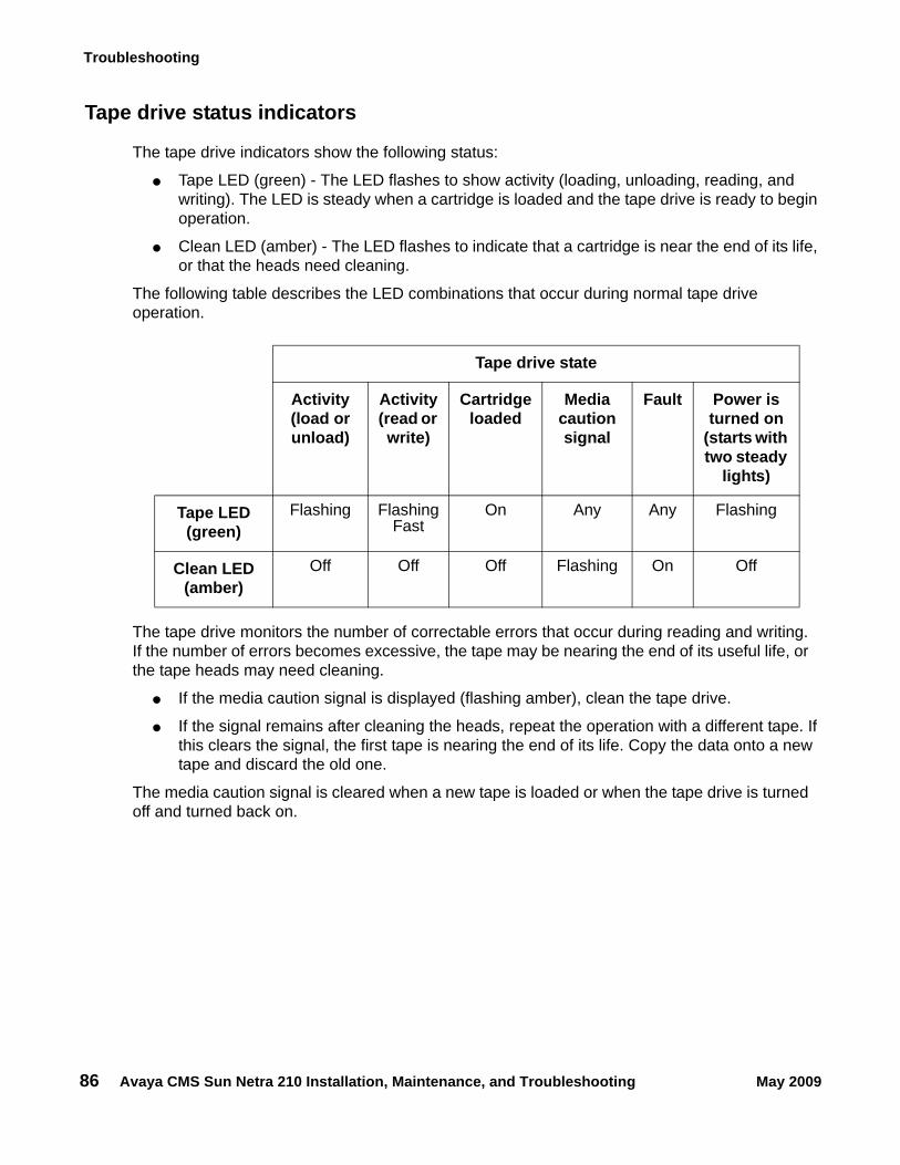
Troubleshooting
86 Avaya CMS Sun Netra 210 Installation, Maintenance, and Troubleshooting May 2009
Tape drive status indicators
The tape drive indicators show the following status:
● Tape LED (green) - The LED flashes to show activity (loading, unloading, reading, and writing). The LED is steady when a cartridge is loaded and the tape drive is ready to begin operation.
● Clean LED (amber) - The LED flashes to indicate that a cartridge is near the end of its life, or that the heads need cleaning.
The following table describes the LED combinations that occur during normal tape drive operation.
The tape drive monitors the number of correctable errors that occur during reading and writing. If the number of errors becomes excessive, the tape may be nearing the end of its useful life, or the tape heads may need cleaning.
● If the media caution signal is displayed (flashing amber), clean the tape drive.
● If the signal remains after cleaning the heads, repeat the operation with a different tape. If this clears the signal, the first tape is nearing the end of its life. Copy the data onto a new tape and discard the old one.
The media caution signal is cleared when a new tape is loaded or when the tape drive is turned off and turned back on.
Tape drive state
Activity (load or unload)
Activity (read or write)
Cartridge loaded
Media caution signal
Fault Power is turned on
(starts with two steady
lights)
Tape LED (green)
Flashing Flashing Fast
On Any Any Flashing
Clean LED (amber)
Off Off Off Flashing On Off
Tools
Avaya CMS Sun Netra 210 Installation, Maintenance, and Troubleshooting May 2009 87
Sun Validation Test Suite (VTS)The SunVTS supports diagnostics in the following areas:
● Connection test - Minimal access of device to verify its accessibility and availability.
● Functional test (default) - Detailed tests to thoroughly test the device or system when offline the system is offline (CMS must be turned off). A stress mode in the system or test option can be set only within the offline mode. The stress mode is an extension of offline.
● Functional test (from system monitor) - Safe tests that can be executed on the device or system when it is online (CMS can be on, but testing is safer when it is turned off).
There are two ways to run SunVTS. We recommend that you use either local access through the Common Desktop Environment (CDE) interface, or remote access using an ASCII interface.
Prerequisites
CMS must be turned off.
Using SunVTS
To use SunVTS:
1. Enter:
BYPASS_FS_PROBE=1; export BYPASS_FS_PROBE
This bypasses the file system probe.
2. Do one of the following:
● Enter:
/opt/SUNWvts/bin/sunvts
This accesses the CDE interface.
● Enter:
/opt/SUNWvts/bin/sunvts -t
This accesses the TTY mode (ASCII interface).
Additional references: For more information about using VTS, see /opt/SUNWvts/README and /opt/SUNWvts/bin/vtstty.help.
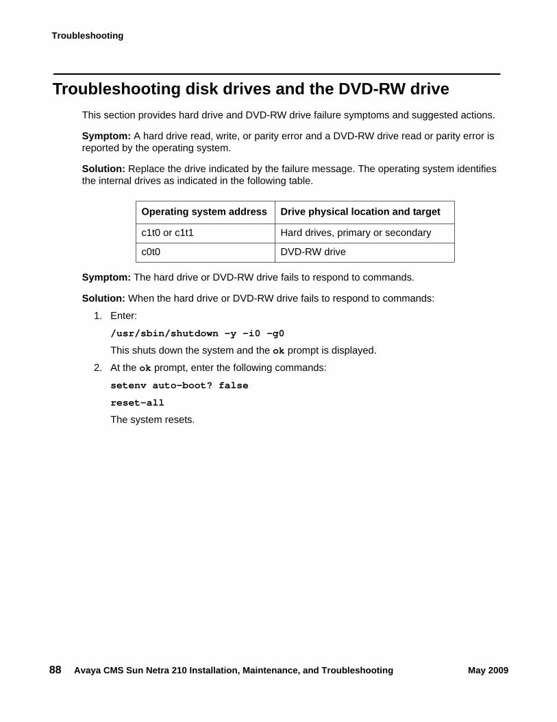
Troubleshooting
88 Avaya CMS Sun Netra 210 Installation, Maintenance, and Troubleshooting May 2009
Troubleshooting disk drives and the DVD-RW driveThis section provides hard drive and DVD-RW drive failure symptoms and suggested actions.
Symptom: A hard drive read, write, or parity error and a DVD-RW drive read or parity error is reported by the operating system.
Solution: Replace the drive indicated by the failure message. The operating system identifies the internal drives as indicated in the following table.
Symptom: The hard drive or DVD-RW drive fails to respond to commands.
Solution: When the hard drive or DVD-RW drive fails to respond to commands:
1. Enter:
/usr/sbin/shutdown -y -i0 -g0
This shuts down the system and the ok prompt is displayed.
2. At the ok prompt, enter the following commands:
setenv auto-boot? false
reset-all
The system resets.
Operating system address Drive physical location and target
c1t0 or c1t1 Hard drives, primary or secondary
c0t0 DVD-RW drive
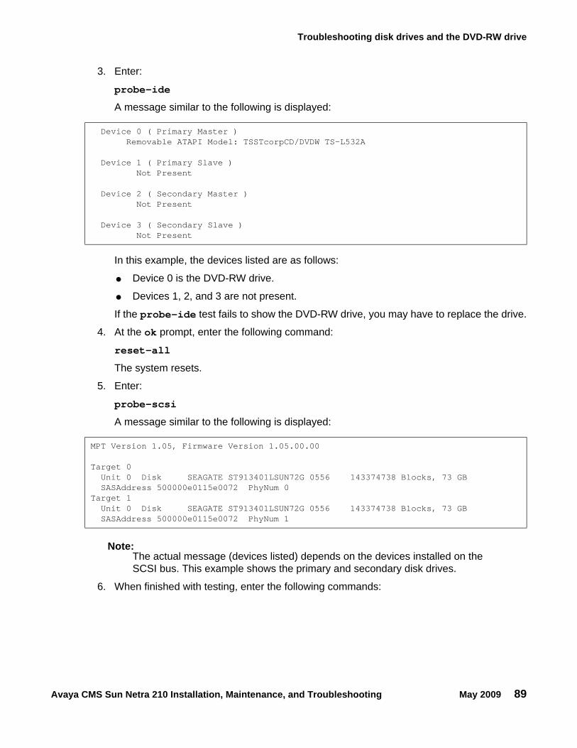
Troubleshooting disk drives and the DVD-RW drive
Avaya CMS Sun Netra 210 Installation, Maintenance, and Troubleshooting May 2009 89
3. Enter:
probe-ide
A message similar to the following is displayed:
In this example, the devices listed are as follows:
● Device 0 is the DVD-RW drive.
● Devices 1, 2, and 3 are not present.
If the probe-ide test fails to show the DVD-RW drive, you may have to replace the drive.
4. At the ok prompt, enter the following command:
reset-all
The system resets.
5. Enter:
probe-scsi
A message similar to the following is displayed:
Note:Note: The actual message (devices listed) depends on the devices installed on the
SCSI bus. This example shows the primary and secondary disk drives.
6. When finished with testing, enter the following commands:
Device 0 ( Primary Master )Removable ATAPI Model: TSSTcorpCD/DVDW TS-L532A
Device 1 ( Primary Slave )Not Present
Device 2 ( Secondary Master )Not Present
Device 3 ( Secondary Slave )Not Present
MPT Version 1.05, Firmware Version 1.05.00.00
Target 0Unit 0 Disk SEAGATE ST913401LSUN72G 0556 143374738 Blocks, 73 GBSASAddress 500000e0115e0072 PhyNum 0
Target 1Unit 0 Disk SEAGATE ST913401LSUN72G 0556 143374738 Blocks, 73 GBSASAddress 500000e0115e0072 PhyNum 1
Troubleshooting
90 Avaya CMS Sun Netra 210 Installation, Maintenance, and Troubleshooting May 2009
CAUTION:!
CAUTION: If you fail to enter these commands, any reboots that you do in the future will stop at the boot prompt instead of proceeding through the normal boot-up process.
setenv auto-boot? true
boot
The system reboots.
Troubleshooting tape drivesUse the following procedures to troubleshoot tape drives:
● Checking tape status
● Reassigning device instance numbers for tape devices on page 92
Checking tape statusFor many procedures, you must identify what tape drive, by device path, you will use for the procedure. Tape drives are assigned to particular device paths, usually one of the following:
● /dev/rmt/0
● /dev/rmt/0c
● /dev/rmt/1
● /dev/rmt/1c
Note:Note: The letter c at the end of the device name indicates that the tape device can
operate in compressed mode. We recommend that you use compressed mode at all times.
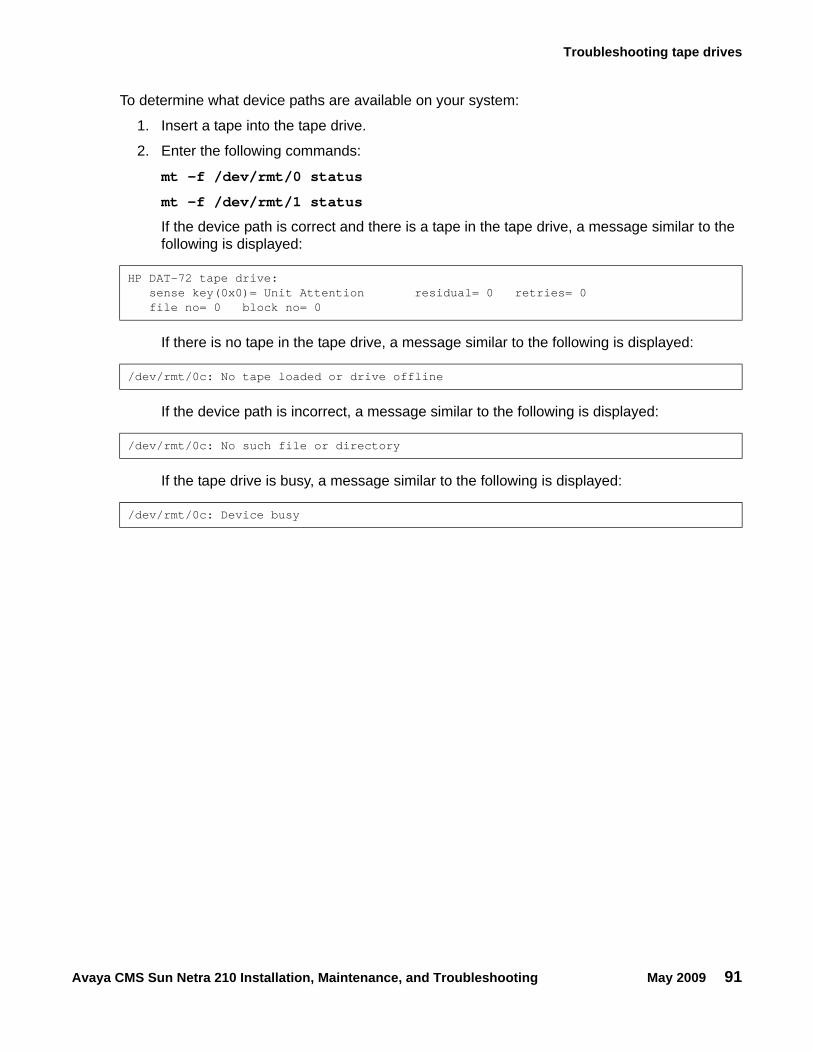
Troubleshooting tape drives
Avaya CMS Sun Netra 210 Installation, Maintenance, and Troubleshooting May 2009 91
To determine what device paths are available on your system:
1. Insert a tape into the tape drive.
2. Enter the following commands:
mt -f /dev/rmt/0 status
mt -f /dev/rmt/1 status
If the device path is correct and there is a tape in the tape drive, a message similar to the following is displayed:
If there is no tape in the tape drive, a message similar to the following is displayed:
If the device path is incorrect, a message similar to the following is displayed:
If the tape drive is busy, a message similar to the following is displayed:
HP DAT-72 tape drive: sense key(0x0)= Unit Attention residual= 0 retries= 0 file no= 0 block no= 0
/dev/rmt/0c: No tape loaded or drive offline
/dev/rmt/0c: No such file or directory
/dev/rmt/0c: Device busy
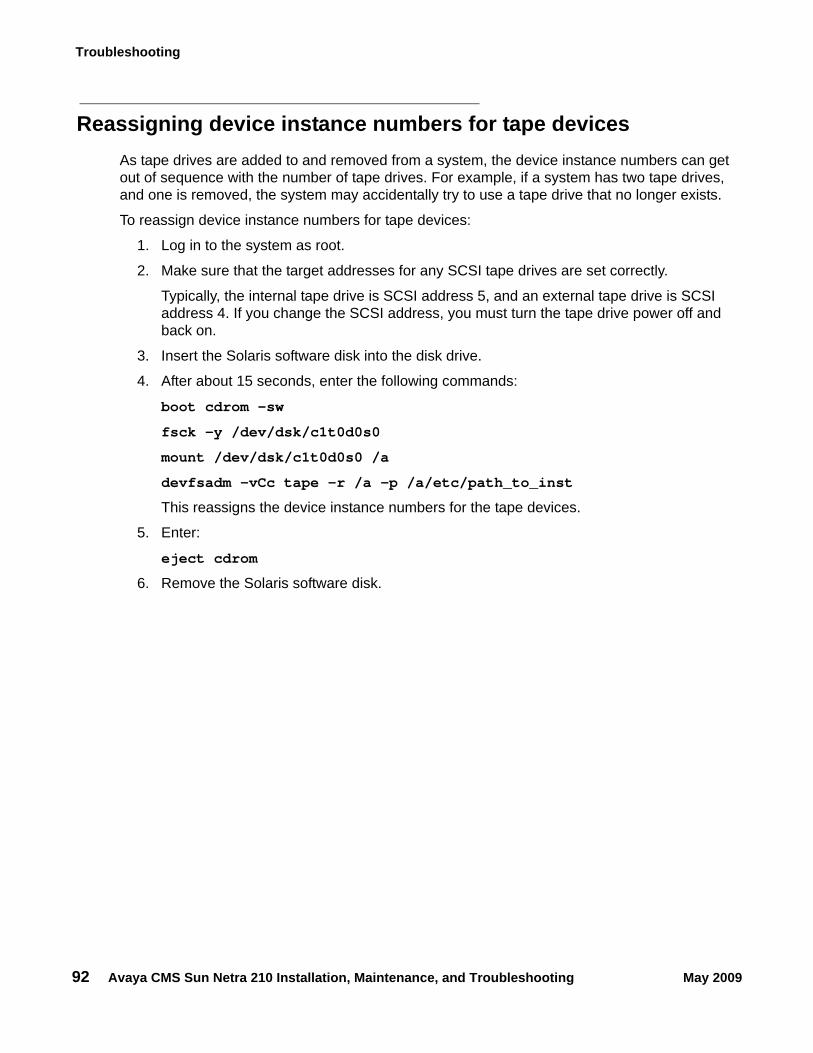
Troubleshooting
92 Avaya CMS Sun Netra 210 Installation, Maintenance, and Troubleshooting May 2009
Reassigning device instance numbers for tape devicesAs tape drives are added to and removed from a system, the device instance numbers can get out of sequence with the number of tape drives. For example, if a system has two tape drives, and one is removed, the system may accidentally try to use a tape drive that no longer exists.
To reassign device instance numbers for tape devices:
1. Log in to the system as root.
2. Make sure that the target addresses for any SCSI tape drives are set correctly.
Typically, the internal tape drive is SCSI address 5, and an external tape drive is SCSI address 4. If you change the SCSI address, you must turn the tape drive power off and back on.
3. Insert the Solaris software disk into the disk drive.
4. After about 15 seconds, enter the following commands:
boot cdrom -sw
fsck -y /dev/dsk/c1t0d0s0
mount /dev/dsk/c1t0d0s0 /a
devfsadm -vCc tape -r /a -p /a/etc/path_to_inst
This reassigns the device instance numbers for the tape devices.
5. Enter:
eject cdrom
6. Remove the Solaris software disk.
Recovery procedures
Avaya CMS Sun Netra 210 Installation, Maintenance, and Troubleshooting May 2009 93
Recovery proceduresThis section provides solutions for the following problems:
● Preserving data after a system failure on page 93
● Loss of power on page 94
● Probe command warnings on page 95
● Remote console port problems on page 96
Preserving data after a system failureEnter the sync command at the ok prompt to force any information on its way to the hard disk to be written out immediately. This is useful if the operating system fails or is interrupted before preserving all data.
The sync command returns control to the operating system and performs the data-saving operations. After the disk data is synchronized, the operating system begins to save a core image of itself. If you do not need this core dump, you can interrupt the operation by pressing Stop+A.
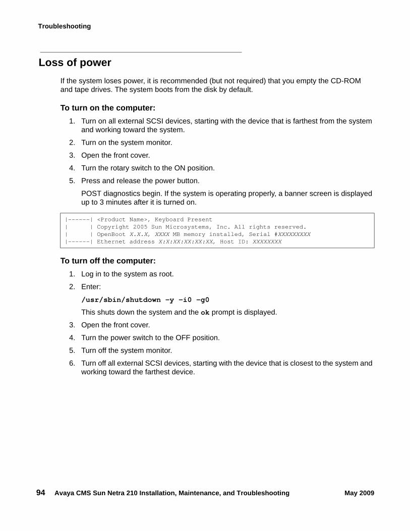
Troubleshooting
94 Avaya CMS Sun Netra 210 Installation, Maintenance, and Troubleshooting May 2009
Loss of powerIf the system loses power, it is recommended (but not required) that you empty the CD-ROM and tape drives. The system boots from the disk by default.
To turn on the computer:1. Turn on all external SCSI devices, starting with the device that is farthest from the system
and working toward the system.
2. Turn on the system monitor.
3. Open the front cover.
4. Turn the rotary switch to the ON position.
5. Press and release the power button.
POST diagnostics begin. If the system is operating properly, a banner screen is displayed up to 3 minutes after it is turned on.
To turn off the computer:1. Log in to the system as root.
2. Enter:
/usr/sbin/shutdown -y -i0 -g0
This shuts down the system and the ok prompt is displayed.
3. Open the front cover.
4. Turn the power switch to the OFF position.
5. Turn off the system monitor.
6. Turn off all external SCSI devices, starting with the device that is closest to the system and working toward the farthest device.
|------| <Product Name>, Keyboard Present| | Copyright 2005 Sun Microsystems, Inc. All rights reserved.| | OpenBoot X.X.X, XXXX MB memory installed, Serial #XXXXXXXXX|------| Ethernet address X:X:XX:XX:XX:XX, Host ID: XXXXXXXX
Recovery procedures
Avaya CMS Sun Netra 210 Installation, Maintenance, and Troubleshooting May 2009 95
Probe command warningsSymptom: When using any of the "probe" commands, the following message is displayed:
CAUTION:!
CAUTION: Do not continue. Answer n. Do not answer y.
Solution: To recover from this condition:
1. Enter: n
This stops the probe command.
2. Enter the following commands:
setenv auto-boot? false
reset-all
3. Now it is acceptable to execute any of the "probe" commands and perform any other boot PROM-level diagnostics.
4. After you finish probing the system devices, enter the following commands:
CAUTION:!
CAUTION: If you fail to enter these commands, any reboots that you do in the future will stop at the boot prompt instead of proceeding through the normal boot-up process.
setenv auto-boot? true
boot
The system reboots.
This command may hang the system if a Stop-A or halt command has been executed. Please type reset-all to reset the system before executing this command. Do you wish to continue [Y/N].
Troubleshooting
96 Avaya CMS Sun Netra 210 Installation, Maintenance, and Troubleshooting May 2009
Remote console port problemsThis section contains problems you may encounter with the remote console port.
Symptom: The remote console port will not initialize for dialing in or dialing out.
Solution: To correct this problem:
1. Enter:
sacadm -l
If the system status reports NO_SAC, the port is not working properly.
2. Enter:
/cms/install/bin/abcadm -i -b 9600 ttyb
The following message should be displayed:
If this message is not displayed, continue with Step 3.
3. Enter:
/cms/install/bin/abcadm -r ttyb
The following message is displayed:
4. Enter: y
The following message is displayed:
The port monitor turns off.
5. Enter:
ps -ef | grep sac
This finds any SAC processes that are running. If any processes are found, continue with Step 6. Otherwise, continue with Step 7.
6. Enter:
kill -9 <pid>
Use this command to kill any SAC processes still running. Process numbers are represented by <pid>.
ttyb set to incoming port 9600 baud
ttyb is currently set to be incoming
Are you sure you want to change it? [y,n,?]
ttyb administration removed
Recovery procedures
Avaya CMS Sun Netra 210 Installation, Maintenance, and Troubleshooting May 2009 97
7. Enter:
/usr/lib/saf/sac -t 300
This restarts SAC.
8. Enter:
sacadm -l
Confirm that SAC is running. The system should report the port status as ENABLED.
9. Enter:
/cms/install/bin/abcadm -i -b 9600 ttyb
The following message should be displayed:
If this message is not displayed, escalate the problem using the normal channels.
ttyb set to incoming port 9600 baud
Troubleshooting
98 Avaya CMS Sun Netra 210 Installation, Maintenance, and Troubleshooting May 2009
Symptom: The system cannot dial out to report alarms using the Alarm Origination Manager (AOM).
Solution: To correct this problem:
1. Enter:
tail /etc/uucp/Devices
The system should display the following:
2. Check the settings on the remote console modem. For the U.S. Robotics modem, make sure that DIP switches 4 and 8 are down (ON). If these switches are not set correctly, you may still be able to dial in, but it may not dial out.
3. Enter:
/opt/cc/install/aot.cssr1Xxx.x/bin/setup
This restarts AOM. The release number Xxx.x depends on your installation.
To send a test alarm:
1. Enter the following commands to set up the test environment:
. /opt/cc/aot/bin/aom_env
cd /opt/cc/aot/bin
aom start
export PRODUCT_TYPE=TEST
2. Enter:
./log_error -e 30001 -d "test alarm"
This sends a test alarm.
3. Enter:
./alarm_view -p TEST -a TEST_ALARM
This will display the test alarm.
4. Enter:
./alarm_resolve -p TEST -a TEST_ALARM
This resolves the test alarm.
5. Enter:
tail -f aom_log
The AOM log file is displayed.
ACU cua/b - Any HayesDirect cua/a - Any DirectDirect cua/b - Any Direct
Recovery procedures
Avaya CMS Sun Netra 210 Installation, Maintenance, and Troubleshooting May 2009 99
6. If you change an AOM parameter, such as the product ID or the telephone number, you must turn AOM off and back on again to recognize the new parameters. These parameters are in /opt/cc/aot/data/admin/sysSetup.cfg file. Be sure to set the port to value 1 for ttyb.
7. If the /opt/cc/aom/data/log file has the message "aom cms alarm is disabled", enter:
export PRODUCT_TYPE=TEST
This enables the alarm.

Troubleshooting
100 Avaya CMS Sun Netra 210 Installation, Maintenance, and Troubleshooting May 2009
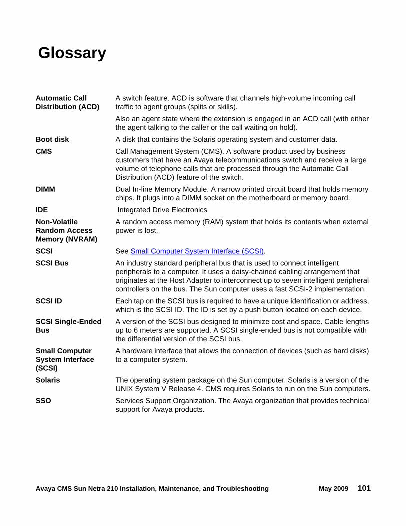
Avaya CMS Sun Netra 210 Installation, Maintenance, and Troubleshooting May 2009 101
Glossary
Automatic Call Distribution (ACD)
A switch feature. ACD is software that channels high-volume incoming call traffic to agent groups (splits or skills).Also an agent state where the extension is engaged in an ACD call (with either the agent talking to the caller or the call waiting on hold).
Boot disk A disk that contains the Solaris operating system and customer data.CMS Call Management System (CMS). A software product used by business
customers that have an Avaya telecommunications switch and receive a large volume of telephone calls that are processed through the Automatic Call Distribution (ACD) feature of the switch.
DIMM Dual In-line Memory Module. A narrow printed circuit board that holds memory chips. It plugs into a DIMM socket on the motherboard or memory board.
IDE Integrated Drive ElectronicsNon-Volatile Random Access Memory (NVRAM)
A random access memory (RAM) system that holds its contents when external power is lost.
SCSI See Small Computer System Interface (SCSI).SCSI Bus An industry standard peripheral bus that is used to connect intelligent
peripherals to a computer. It uses a daisy-chained cabling arrangement that originates at the Host Adapter to interconnect up to seven intelligent peripheral controllers on the bus. The Sun computer uses a fast SCSI-2 implementation.
SCSI ID Each tap on the SCSI bus is required to have a unique identification or address, which is the SCSI ID. The ID is set by a push button located on each device.
SCSI Single-Ended Bus
A version of the SCSI bus designed to minimize cost and space. Cable lengths up to 6 meters are supported. A SCSI single-ended bus is not compatible with the differential version of the SCSI bus.
Small Computer System Interface (SCSI)
A hardware interface that allows the connection of devices (such as hard disks) to a computer system.
Solaris The operating system package on the Sun computer. Solaris is a version of the UNIX System V Release 4. CMS requires Solaris to run on the Sun computers.
SSO Services Support Organization. The Avaya organization that provides technical support for Avaya products.

SSO
102 Avaya CMS Sun Netra 210 Installation, Maintenance, and Troubleshooting May 2009
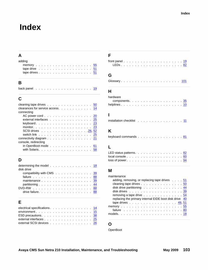
Avaya CMS Sun Netra 210 Installation, Maintenance, and Troubleshooting May 2009 103
Index
Index
Aadding
memory . . . . . . . . . . . . . . . . . . . . 55tape drive . . . . . . . . . . . . . . . . . . . 51tape drives . . . . . . . . . . . . . . . . . . . 51
Bback panel . . . . . . . . . . . . . . . . . . . . 19
Ccleaning tape drives . . . . . . . . . . . . . . . . 50clearances for service access. . . . . . . . . . . . 14connecting
AC power cord . . . . . . . . . . . . . . . . . 20external interfaces . . . . . . . . . . . . . . . 25keyboard . . . . . . . . . . . . . . . . . . . . 23monitor. . . . . . . . . . . . . . . . . . . . . 23SCSI drives . . . . . . . . . . . . . . . . .26, 52switch link . . . . . . . . . . . . . . . . . . . 25
connectivity diagram . . . . . . . . . . . . . . . . 21console, redirecting
in OpenBoot mode . . . . . . . . . . . . . . . 61with Solaris. . . . . . . . . . . . . . . . . . . 58
Ddetermining the model . . . . . . . . . . . . . . . 18disk drive
compatibility with CMS . . . . . . . . . . . . . 39failure . . . . . . . . . . . . . . . . . . . . . 88maintenance . . . . . . . . . . . . . . . . . . 39partitioning . . . . . . . . . . . . . . . . . . . 44
DVD-RW . . . . . . . . . . . . . . . . . . . . . 88drive failure. . . . . . . . . . . . . . . . . . . 88
Eelectrical specifications . . . . . . . . . . . . . . . 14environment . . . . . . . . . . . . . . . . . . . . 15ESD precautions. . . . . . . . . . . . . . . . . . 38external interfaces . . . . . . . . . . . . . . . . . 25external SCSI devices . . . . . . . . . . . . . . . 26
Ffront panel . . . . . . . . . . . . . . . . . . . . . 19
LEDs . . . . . . . . . . . . . . . . . . . . . . 82
GGlossary . . . . . . . . . . . . . . . . . . . . . 101
Hhardware
components. . . . . . . . . . . . . . . . . . . 35helplines . . . . . . . . . . . . . . . . . . . . . . 10
Iinstallation checklist . . . . . . . . . . . . . . . . 11
Kkeyboard commands . . . . . . . . . . . . . . . . 81
LLED status patterns. . . . . . . . . . . . . . . . . 82local console . . . . . . . . . . . . . . . . . . . . 60loss of power . . . . . . . . . . . . . . . . . . . . 94
Mmaintenance
adding, removing, or replacing tape drives . . . . 51cleaning tape drives . . . . . . . . . . . . . . . 50disk drive partitioning . . . . . . . . . . . . . . 44disk drives . . . . . . . . . . . . . . . . . . . 39removing a tape drive . . . . . . . . . . . . . . 54replacing the primary internal EIDE boot disk drive 40tape drives . . . . . . . . . . . . . . . . . 49, 51
memory . . . . . . . . . . . . . . . . . . . . . . 55failure . . . . . . . . . . . . . . . . . . . . . 80
models. . . . . . . . . . . . . . . . . . . . . . . 18
OOpenBoot
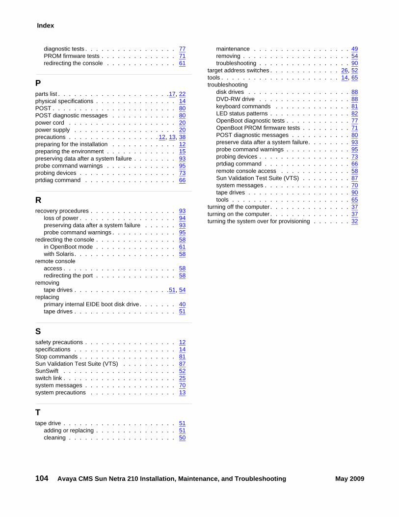
104 Avaya CMS Sun Netra 210 Installation, Maintenance, and Troubleshooting May 2009
Index
diagnostic tests . . . . . . . . . . . . . . . . . 77PROM firmware tests . . . . . . . . . . . . . . 71redirecting the console . . . . . . . . . . . . . 61
Pparts list . . . . . . . . . . . . . . . . . . . . .17, 22physical specifications . . . . . . . . . . . . . . . 14POST . . . . . . . . . . . . . . . . . . . . . . . 80POST diagnostic messages . . . . . . . . . . . . 80power cord . . . . . . . . . . . . . . . . . . . . 20power supply . . . . . . . . . . . . . . . . . . . 20precautions . . . . . . . . . . . . . . . . . 12, 13, 38preparing for the installation . . . . . . . . . . . . 12preparing the environment . . . . . . . . . . . . . 15preserving data after a system failure . . . . . . . . 93probe command warnings . . . . . . . . . . . . . 95probing devices . . . . . . . . . . . . . . . . . . 73prtdiag command . . . . . . . . . . . . . . . . . 66
Rrecovery procedures . . . . . . . . . . . . . . . . 93
loss of power . . . . . . . . . . . . . . . . . . 94preserving data after a system failure . . . . . . 93probe command warnings . . . . . . . . . . . . 95
redirecting the console . . . . . . . . . . . . . . . 58in OpenBoot mode . . . . . . . . . . . . . . . 61with Solaris. . . . . . . . . . . . . . . . . . . 58
remote consoleaccess . . . . . . . . . . . . . . . . . . . . . 58redirecting the port . . . . . . . . . . . . . . . 58
removingtape drives . . . . . . . . . . . . . . . . . .51, 54
replacingprimary internal EIDE boot disk drive. . . . . . . 40tape drives . . . . . . . . . . . . . . . . . . . 51
Ssafety precautions . . . . . . . . . . . . . . . . . 12specifications . . . . . . . . . . . . . . . . . . . 14Stop commands . . . . . . . . . . . . . . . . . . 81Sun Validation Test Suite (VTS) . . . . . . . . . . 87SunSwift . . . . . . . . . . . . . . . . . . . . . 52switch link . . . . . . . . . . . . . . . . . . . . . 25system messages . . . . . . . . . . . . . . . . . 70system precautions . . . . . . . . . . . . . . . . 13
Ttape drive . . . . . . . . . . . . . . . . . . . . . 51
adding or replacing . . . . . . . . . . . . . . . 51cleaning . . . . . . . . . . . . . . . . . . . . 50
maintenance . . . . . . . . . . . . . . . . . . 49removing . . . . . . . . . . . . . . . . . . . . 54troubleshooting . . . . . . . . . . . . . . . . . 90
target address switches . . . . . . . . . . . . . 26, 52tools . . . . . . . . . . . . . . . . . . . . . . 14, 65troubleshooting
disk drives . . . . . . . . . . . . . . . . . . . 88DVD-RW drive . . . . . . . . . . . . . . . . . 88keyboard commands . . . . . . . . . . . . . . 81LED status patterns . . . . . . . . . . . . . . . 82OpenBoot diagnostic tests . . . . . . . . . . . . 77OpenBoot PROM firmware tests . . . . . . . . . 71POST diagnostic messages . . . . . . . . . . . 80preserve data after a system failure. . . . . . . . 93probe command warnings . . . . . . . . . . . . 95probing devices . . . . . . . . . . . . . . . . . 73prtdiag command . . . . . . . . . . . . . . . . 66remote console access . . . . . . . . . . . . . 58Sun Validation Test Suite (VTS) . . . . . . . . . 87system messages . . . . . . . . . . . . . . . . 70tape drives . . . . . . . . . . . . . . . . . . . 90tools . . . . . . . . . . . . . . . . . . . . . . 65
turning off the computer . . . . . . . . . . . . . . . 37turning on the computer . . . . . . . . . . . . . . . 37turning the system over for provisioning . . . . . . . 32