Embed Size (px)
Citation preview
AVERT: An Autonomous Multi-Robot System for Vehicle Extractionand Transportation
Angelos Amanatiadis, Christopher Henschel, Bernd Birkicht, Benjamin Andel,Konstantinos Charalampous, Ioannis Kostavelis, Richard May, and Antonios Gasteratos
Abstract— This paper presents a multi-robot system forautonomous vehicle extraction and transportation based on the“a-robot-for-a-wheel” concept. The developed prototype is ableto extract vehicles from confined spaces with delicate handling,swiftly and in any direction. The novel lifting robots are capableof omnidirectional movement, thus they can under-ride thedesired vehicle and dock to its wheels for a synchronized liftingand extraction. The overall developed system applies reasoningabout available trajectory paths, wheel identification, local andundercarriage obstacle detection, in order to fully automatethe process. The validity and efficiency of the AVERT roboticsystem is illustrated via experiments in an indoor parkinglot, demonstrating successful autonomous navigation, docking,lifting and transportation of a conventional vehicle.
I. INTRODUCTION
Conventional car lifting and transportation systems arecharacterized by time-consuming solutions which demandhuman intervention in the loop. Their lifting and extractionconfigurations include towing, ropes and wheel lifter jacks.What is more, the current solutions are inadequate withinconfined spaces such as indoor parking lots, where the routeclearance can often be performed only partially or even notat all, as access with conventional towing equipment cannotbe guaranteed.
Automating the car lifting and transportation process willhave a strong impact in several fields such as parkinggarages, emergency towing away services and explosiveordnance disposal by providing a faster and safer removalcapability compared with the manual methods currentlyavailable.
In this paper we propose an autonomous multi-robotsystem for the remote lifting and transportation of vehicleswith human intervention only in the decision making loop(which car to be moved and where to be transferred). The
The research work is supported by the E.C. under the FP7 research projectfor The Autonomous Vehicle Emergency Recovery Tool to provide a robotpath planning and navigation tool, “AVERT”, FP7-SEC-2011-1-285092.
Angelos Amanatiadis, Konstantinos Charalampous, IoannisKostavelis, and Antonios Gasteratos are with School ofEngineering, Democritus University of Thrace, 12 Vas. Sofias,GR-67100, Xanthi, Greece [email protected],{kchara,gkostave,agaster}@pme.duth.gr
Christopher Henschel is with the Zurich University of Applied Sciences,Technikumstrasse 5, CH-8401, Winterthur, Switzerland [email protected]
Bernd Birkicht is with the BB-Ingenieure, Im Pfarracker 17/1, D-71723,Grossbottwar, Germany [email protected]
Benjamin Andel is with the Force Ware GmbH, Arbachtalstrasse 10, D-72800, Eningen, Germany [email protected]
Richard May is with the IDUS Consultancy Ltd, 10Lime Close, RG41 4AW, Wokingham, United [email protected]
Fig. 1. The autonomous AVERT robot prototype.
novel developed robots, as shown in Fig. 1, are used tolift the selected vehicle from underneath by docking toits tires, and remain inside the vehicle’s footprint duringlifting and extraction in order to maximize the opportunitiesfor successful use when operating in confined spaces. Theconceptual prototype was presented in [1], with this paperdescribing the detailed and final prototype with integratedautonomous functions.
II. RELATED WORK
A car transportation system able to support tasks suchas parking, valet parking, and towing away services hasbeen developed in Tohoku University [2], [3]. The roboticsystem was developed for parking purposes and consists oftwo robots being controlled by a decentralized algorithmfor car transportation. Initially, the first robot grasps thetwo wheels on the left side of a four-wheeled car, whilstthe second one grips the other two. Then, the two robotstransport the car in coordination. The extracted trajectory isprovided to the first robot, whilst the other one estimatesits trajectory through the interaction force between them.An improved and downsized version of the first prototypewas finalized at the same University [4], [5], based on the“a-robot-for-a-wheel” concept. The new version consists offour car transportation robots that can lift up and supporta wheel of the car. Each robot slides two lift-bars underboth sides of the wheel and then moves two racks on eitherside of a pinion to the opposite directions by rotating thepinion. Furthermore, a new decentralized control algorithmfor coordinated car transportation was proposed, by usinga leader-follower strategy and enabling the followers toestimate and reduce the motion errors.
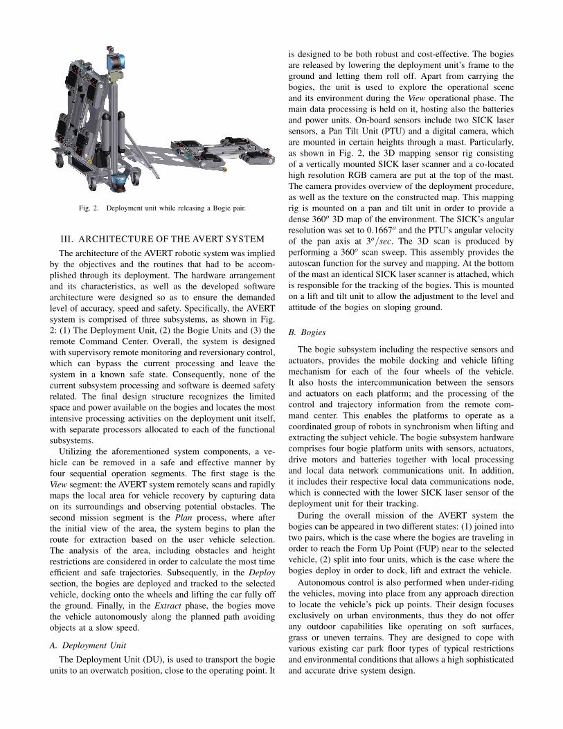
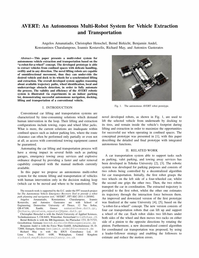
Fig. 2. Deployment unit while releasing a Bogie pair.
III. ARCHITECTURE OF THE AVERT SYSTEM
The architecture of the AVERT robotic system was impliedby the objectives and the routines that had to be accom-plished through its deployment. The hardware arrangementand its characteristics, as well as the developed softwarearchitecture were designed so as to ensure the demandedlevel of accuracy, speed and safety. Specifically, the AVERTsystem is comprised of three subsystems, as shown in Fig.2: (1) The Deployment Unit, (2) the Bogie Units and (3) theremote Command Center. Overall, the system is designedwith supervisory remote monitoring and reversionary control,which can bypass the current processing and leave thesystem in a known safe state. Consequently, none of thecurrent subsystem processing and software is deemed safetyrelated. The final design structure recognizes the limitedspace and power available on the bogies and locates the mostintensive processing activities on the deployment unit itself,with separate processors allocated to each of the functionalsubsystems.
Utilizing the aforementioned system components, a ve-hicle can be removed in a safe and effective manner byfour sequential operation segments. The first stage is theView segment: the AVERT system remotely scans and rapidlymaps the local area for vehicle recovery by capturing dataon its surroundings and observing potential obstacles. Thesecond mission segment is the Plan process, where afterthe initial view of the area, the system begins to plan theroute for extraction based on the user vehicle selection.The analysis of the area, including obstacles and heightrestrictions are considered in order to calculate the most timeefficient and safe trajectories. Subsequently, in the Deploysection, the bogies are deployed and tracked to the selectedvehicle, docking onto the wheels and lifting the car fully offthe ground. Finally, in the Extract phase, the bogies movethe vehicle autonomously along the planned path avoidingobjects at a slow speed.
A. Deployment Unit
The Deployment Unit (DU), is used to transport the bogieunits to an overwatch position, close to the operating point. It
is designed to be both robust and cost-effective. The bogiesare released by lowering the deployment unit’s frame to theground and letting them roll off. Apart from carrying thebogies, the unit is used to explore the operational sceneand its environment during the View operational phase. Themain data processing is held on it, hosting also the batteriesand power units. On-board sensors include two SICK lasersensors, a Pan Tilt Unit (PTU) and a digital camera, whichare mounted in certain heights through a mast. Particularly,as shown in Fig. 2, the 3D mapping sensor rig consistingof a vertically mounted SICK laser scanner and a co-locatedhigh resolution RGB camera are put at the top of the mast.The camera provides overview of the deployment procedure,as well as the texture on the constructed map. This mappingrig is mounted on a pan and tilt unit in order to provide adense 360o 3D map of the environment. The SICK’s angularresolution was set to 0.1667o and the PTU’s angular velocityof the pan axis at 3o/sec. The 3D scan is produced byperforming a 360o scan sweep. This assembly provides theautoscan function for the survey and mapping. At the bottomof the mast an identical SICK laser scanner is attached, whichis responsible for the tracking of the bogies. This is mountedon a lift and tilt unit to allow the adjustment to the level andattitude of the bogies on sloping ground.
B. Bogies
The bogie subsystem including the respective sensors andactuators, provides the mobile docking and vehicle liftingmechanism for each of the four wheels of the vehicle.It also hosts the intercommunication between the sensorsand actuators on each platform; and the processing of thecontrol and trajectory information from the remote com-mand center. This enables the platforms to operate as acoordinated group of robots in synchronism when lifting andextracting the subject vehicle. The bogie subsystem hardwarecomprises four bogie platform units with sensors, actuators,drive motors and batteries together with local processingand local data network communications unit. In addition,it includes their respective local data communications node,which is connected with the lower SICK laser sensor of thedeployment unit for their tracking.
During the overall mission of the AVERT system thebogies can be appeared in two different states: (1) joined intotwo pairs, which is the case where the bogies are traveling inorder to reach the Form Up Point (FUP) near to the selectedvehicle, (2) split into four units, which is the case where thebogies deploy in order to dock, lift and extract the vehicle.
Autonomous control is also performed when under-ridingthe vehicles, moving into place from any approach directionto locate the vehicle’s pick up points. Their design focusesexclusively on urban environments, thus they do not offerany outdoor capabilities like operating on soft surfaces,grass or uneven terrains. They are designed to cope withvarious existing car park floor types of typical restrictionsand environmental conditions that allows a high sophisticatedand accurate drive system design.

SPLITTED
DOCKED
JOINED
INITIAL FINAL
LOADED
LIFT BARS OPENED
[docking]
[extending lift rollers]
[loading]
[mission accomplished]
[closing lift rollers]
[undocking]
[unloading]
[joining]
[splitting]
Name:Package:Version:Author:
Bogie Basic State ChartState Chart1.0meis
(a)
JOINED
INITIAL SPLITTED
LIFT BARS OPENED
DOCKED
LOADED
Initial
LOADED LIFT BARS OPENED JOINED
Final
[mission accomplished][joining][closing lift rollers][undocking][unloading]
[mission accomplished][loading][docking][extending lift rollers][splitting]
Name:Package:Version:Author:
1.0
FINAL
(b)
Sequence: Bogie deployment to load of a vehicle
JOINED
Initial
SPLITTED
LIFT BARS OPENED
DOCKED
LOADED
Final
INITIAL
LOADED
DOCKED
LIFT BARS OPENED
SPLITTED
JOINED
[mission accomplished][joining][closing lift rollers][undocking][unloading]
[mission accomplished][loading][docking][extending lift rollers][splitting]
Name:Package:Version:Author:
Bogie Basic State Chart - SequencesState Chart - Sequences1.0meis
FINAL
(c)
Fig. 3. Bogie states and sequences: a) basic bogie states, b) deploymentand docking state sequence, c) vehicle lifting and extraction state sequence.
After being positioned underneath the target vehicle, thebogie design offers a commanded split of the bogie in twosections, enabling both bogie sections to manoeuvre inde-pendently, dock at the vehicle’s opposite wheels of an axleand lift them off the ground by compressing progressivelytwo rollers against the tire, similar to commercially availablecar movers.
To prepare the Bogie control implementation a state chartof basic bogie states was built. Every bogie state requiresspecific control and therefore a different implementation.Figure 3(a), shows the state chart with all possible statesand transitions. The various states were implemented as astate machine within the respective software component. Twosequences of bogie states are displayed in Fig. 3(b) and Fig.3(c). After bogie deployment from the DU the bogies willbe driven to a specific position in a “JOINED” state, besplitted into two bogies in a “SPLITTED” state, be drivento an appropriate position to extend the lift rollers duringthe“LIFT BARS OPENED” state, dock to the wheel whileat “DOCKED” state and load the vehicle to remove it during“LOADED” state. The second sequence shows the roll-backto get back to initial state of first sequence, from “LOADED”state to “JOINED” state. The states presented in the diagramscan be changed using the given transitions. It is possibleto perform state transitions in a loop if necessary. Thestate machine, which was implemented based on the statechart, allowed the development team to limit and simplifyprocessing flows in the overall architecture.
C. Command Center
Since AVERT is designed to operate beyond line of sightit is important that the proposed solution should be designedto allow users to maintain awareness of the current andplanned operations by the AVERT system and to provide themeans for users to be able to assess when user intervention
is needed, allowing timely and effective user override to beactioned. Hence, a Graphical User Interface (GUI) has beendesigned to provide the users all the necessary informationduring the deployment and operation of the system. Addi-tionally, the user should have the advantage to interfere withthe system in the different steps of operation and start, stopor reset any process.
The entire system has been integrated into the imple-mented graphical user interface as a toolkit that allows theuser to interact with the system and to execute the subor-dinate routines on demand. Due to the fact that the entiresoftware architecture of the AVERT system is coordinatedby the Robot Operating System (ROS), the developed GUIhas been built on this framework. Therefore, the AVERT GUIwas developed based on ROS, utilizing the Qt framework,which is a system that allows users to interact with andexamine the ROS environment in a visual manner.
IV. BOGIE ROBOT MECHANICAL DESIGN
The typical gross vehicle weight of passenger cars andlight vans is around 2.5 tons and the upper limit by law is3.5 tons. The bogie systems are considered to provide thecapability of lifting and moving vehicles with weights inexcess of these figures according to the actual operationaldeployment. When displacing a lifted vehicle, the bogie’stotally installed driving power is sufficient to move thehooked mass according to the calculated moving parameters.A prerequisite for omnidirectional movement is that the driv-ing power should split within the bogie system to all bogies,forcing them to have separate main drives for each bogiesection. The bogie sections operate as a swarm, so powerstorage is split as well. The main drive system, therefore, isthe battery supply based set of distributed electrical drives.
The omnidirectional movement design [6] permits thecoordinated AVERT bogie units to manoeuvre the vehicle inany direction (literally the vehicle can be moved sideways ordiagonally on the bogies, once the tires have been lifted offthe ground). When required to pick up cars parked narrowlyto walls, pillars or other cars, the bogie system has to operatewithin a confined space. The estimated distances betweensurrounding obstacles and the vehicle to be repositionedare unpredictable, but unobstructed vehicle accessibility ismostly possible from below. Under-riding a vehicle intro-duces several constraints. Mainly the chassis clearance limitsan under-ride type bogie system’s maximum height. A typicalground clearance for private cars is 160mm (within Germanyand Austria the minimum ground clearance is not limited butrecommended at 110mm). The access to a car from beneathis limited by the track width, when this happens either byfront or rear side, and the wheel base, when the access occurssidewards. Due to the fact that track width is always smallerthan the wheel base, the vehicle’s track width constitutes thelimiting measure for the bogie system’s maximum width.
The mechanical design of the bogies has required con-siderable research and design effort to enable the effectivehousing of the mechanical, electrical, power storage, sensor

Fig. 4. Description of the split Bogie components: (1) Double load bearingMecanum wheels, (2) braked omniwheel, (3) side camera and light, (4)lifting rollers, (5) tire docked sensor, (6) electronics box, (7) lifting unit,(8) docking and joining laser sensor, (9) forward obstacle laser sensor, (10)lift motors and gears, (11) joining/splitting magnetic catch, (12) removablebattery unit, (13) joining location peg.
and communications components whilst maintaining the mo-bility and lifting requirements for the subject vehicle. Figure4, shows the bogie design and features based on the outcomeof the research tasks and prototype model trials. In additionto the labeled features, the bogie drive servomotors and theirintegrated controllers are located under the electronics boxesand they drive the Mecanum wheels through a drivetrainlocated in the gearcase on the side of each drive unit.
The drive motors are the integrated controller Lexiumservo motors. The drive motor assembly is fitted with hold-off safety brakes which activate on loss of electrical current.These brakes are designed to be used in conjunction with thesafety stop features of the drive motors on a controlled shut-down and when emergency stop is activated. Concerningthe power source, a rechargeable lithium electric bicyclebattery pack using LiFePO4 chemistry has been selected.This represents an off-the-shelf solution with the lithium ironphosphate battery having one important advantage over otherlithium-ion chemistries in thermal and chemical stability,which improves battery safety, yet it potentially carries about14% less charge than Li-ion ones. Moreover, the Mecanumwheels have been specially engineered to achieve the desiredload capacity following detailed load testing experiments and
stress modeling. The double wheel format is essential inorder to meet the key load requirement and remain withinthe underride height. The omniwheel hub is also remotebraking capable. The simple remote brake on/off approachwas selected to leave the control electronics as simple andcost-effective as possible. The lift stepper motor is a twophase unit with external controller. The electronics unitsare housed in specially designed 3D-print manufacturedenclosures, which are located above the drive motors andinclude the wiring vault for the drive motor connectionsand control signals carried over Ethernet to the integratedcontroller.
V. SOFTWARE COMPONENTS
The running software components are tightly coupledwith the mission segments of AVERT. In the View phase3D mapping and point cloud registration is performed inorder to provide the area perception and calculate the bogiespath trajectories of the Plan segment. During Deploy phase,the bogie tracking and swarm control is active along withpossible re-routing due to new local obstacles detected bythe bogie on-board sensors. Car docking and extraction isperformed in the Extract section, where also the wheeldetection has been carried out. Car unloading and bogiejoining defines the successful mission.
A. View
For the 3D mapping, the sensor mast of the DU isutilized. A SCHUNK PW-70 servo-electric rotary pan-tiltactuator was chosen since it can accurately handle the loadof the laser sensor, the mounting frame and the digitalcamera. The rotation angle for the pan axis was set 360◦,while the maximum acceleration and angular velocity are1440◦/sec2 and 360◦/sec, respectively. Regarding the pointcloud formation, the SICK LMS500 PRO 2D laser scannerwas configured for vertical scanning. In more detail, the fieldof view is 190◦, the angular resolution varies within theinterval [0.1667◦−1◦], the scanning frequency alters in the[25−100] Hz interval, while the scanning range is up to 80m. According to manufacturer’s specifications the standarddeviation of the measurements is of 0.01 m. SICK’s angularresolution was set to 0.1667◦ and PTU’s angular velocityof the pan axis at 3◦/sec. The 3D scan is produced byperforming a 360◦ scan sweep.
Since a single scan sweep in a typical indoor parkinglot will introduce various blind spots, multiple scans canbe performed in different locations, with two scans beingthe best trade-off between scan coverage and required time.The point cloud registration is accomplished into two distinctsteps based on a previous work by the authors [7]. First,a rough estimation of the transformation matrix is givenusing the Fast Point Feature Histograms (FPFH) features [8]followed by the Iterative Closest Point (ICP) algorithm [9]as a refinement step. FPFH are multi-dimensional featuresdescribing the geometry of a point belonging to a 3D pointcloud. This feature derivation method is an expansion ofPFH [10], which allows the on-line calculation of those

features, while it retains the discriminative capabilities ofPFH, making it suitable for on-line applications.
Let us assume that the DU acquires two specific pointclouds at t and t + 1, respectively, such as tP′ and t+1P′.The DU’s specific motion is described with a rotation t
t+1Rand translation matrix t
t+1T and can be estimated by calcu-lating the transformation among the FPFH correspondencesresulted from the two point clouds as tPFPFH = t
t+1R ·t+1PFPFH + t
t+1T . The required rigid body transformationtypically should conform with a sum of quadratic differencesminimization criterion, resulting to a Singular Value De-composition (SVD) optimization problem. By applying themotion transformation on the respective 3D point clouds weobtain a rough alignment and, as a result, the 3D map retainserroneous registrations. It is worth mentioning that for thisrough alignment an initialization step takes place regardingthe orientation of the robot by exploiting the orientationtracker device. Hence, the initially transformed point cloudsare considered for the correction of the motion estimation.The most commonly used algorithm to fine register the 3Dpoint clouds is the ICP one.
However, the novelty of the AVERT software algorithmis that the proposed ICP algorithm considers only the pointsthat belong to specific geometric surfaces in consecutive timeinstances. The successive point clouds share great amountof spatial proximity, due to the fact that a coarse alignmentoccurred during the motion estimation procedure. The benefitfrom this procedure is twofold: firstly we avoid multipleiterations restricting the rigid body transformation search byone order of magnitude in calculation time and, secondly, weincrease the likelihood to achieve an accurate solution. Theseadvantages are feasible due to the fact that the consideredpoints are contained in two successively observed scenes.Concerning the two successive 3D point clouds tP′ and t+1P′,we utilize a point-to-plane ICP algorithm [11], which seeksfor a transformation K, that registers the two point clouds.
The output of the point-to-plane ICP algorithm is a trans-formation K = [tt+1RICP,
tt+1TICP] that aligns the two succes-
sive point clouds. The transformation K is combined withthe initial estimation, as resulted from the FPFH registrationand a refined estimation of the robot’s pose is obtained,i.e. t
t+1Rre f =tt+1R · tt+1RICP and t
t+1Tre f =tt+1T + t
t+1TICP.The calculated t
t+1Rre f and tt+1Tre f are then introduced in
the accurate registration of the successive 3D point clouds.This procedure is performed separately in each time stepand, hence, the 3D map of the explored area is constructedincrementally.
B. Plan
The floor map enriched with the detected obstacles isprovided as an input to a D* Lite method. The latter treatsthe problem as a graph-traversal one. D* Lite is a fast pathplanning and re-planning algorithm suitable for goal-directedrobot navigation in partial known or unknown terrain. D*Lite constitutes an extension of Lifelong Planning A* (LPA*)[12], and one of its most significant additions is the variationwhere the target position changes dynamically during the re-
planning phases. Due to the fact that D* Lite expands LPA*,it also acquires the entire set of attributes that LPA* entailsand its expansion capabilities as well. Compared to othermethodologies, such as the well known D* [13], or CAO[14], D* Lite is simpler, can be rigorously analyzed, canbe extended in various aspects and its efficiency is at leastequal to D*. Regarding the simplicity, D* Lite utilizes asingle tie-breaking rule for the comparison of the priorities,making their maintenance an easy task.
C. Deploy
The bogies operation comprises functionalities to executea path planning algorithm; detect and report obstacles thatthe AVERT’s perception system was unable to include, aswell as to re-plan is such cases. Moreover, once the vehicleof interest is docked, the bogies are in place to operate as aswarm, retaining the aforementioned capabilities.
The bogie tracking is realized using laser scanning tech-nology. The SICK LMS511 laser ranger, which is mounted atthe bottom of the deployment unit, scans the environment atground level, not higher of the bogie height. The tracking isbased on two elements: the bogie shape dimensions and thereflectivity of its sides. To differentiate between the bogiesides and subsequently to detect a certain rotation of thebogie, retro-reflective foil is placed on two certain sides ofthe bogie. The chosen foil causes highest remission valuesof the laser beams which are measured by the laser scanner.
The bogie tracking process is elaborated in the followingsteps. Firstly, a conversion from laser raw data (polar coor-dinates, angle and distance) to Cartesian coordinate systemis performed. A background subtraction is then applied inorder to extract the points constituting the bogie profile. Linedetection using Hough transformation of the extracted edgesof the bogies allows the estimation of the bogie’s orientation.Additionally, this step is used for outlier rejection of non-relevant points located too far from the extracted lines. Thebogie’s center point is calculated based on the extractedbogie edges and their associated points. The identificationof bogie sides is achieved by comparing the mean remissionvalue of the different sides. An optimization of center pointand orientation using the Newton-Raphson algorithm followsalong with a plausibility check for bogie pose position andorientation.
Controlling the four AVERT bogies in a common frame isnecessary and starts on the moment that all four bogies aredocked to the vehicle to be extracted. A basic requirementfor the swarm control is the knowledge of each split bogie’spose. Recognizing the bogie poses, the width and length ofthe swarm as well as the orientation of the bogies to eachother can be derived. The chosen strategy is to rotate theentire car close to its center of geometry until the car frontfaces the next trajectory point and then drive forward towardsthis point. Following this approach, the bogie on-board laserrangers can also scan adequately for local obstacles. Further-more, the whole moving system is more robust when drivingover obstacles, since the Mecanum wheels can overcomeobstacles more efficiently when in forward direction. The

Fig. 5. Visualization of the tracking process: the estimate of the model isrefined using the ICP algorithm to find the actual transformations R and t,which are then used as approximation for the next iteration.
implemented algorithm allows also vehicle rotation withthe rotation center outside of the vehicle’s footprint. Therotation of a bogie around a rotation point C(Cx,Cy) iscalculated in the following steps: (1) Define bogie positionfrom rotation center perspective, (PosBogie−PosRotCenter), (2)Rotate around angle α , PosBogie×R, where R =
(cosα −sinα
sinα cosα
),
and (3) Describe bogie position in original coordinate system(PosBogie +PosRotCentre).
The obstacle detection algorithm is based on the computa-tion of height differences between two or more consecutivemeasurement time steps. The laser scanner is mounted tothe bogie front side with a certain tilt angle α . Based onthe current height h of the light reception coordinates O,the interior angle β and the slope distance s measured bythe laser ranger, we use the equation h = cosβ × s, forcomparing the expected height he, which is known by themechanical construction, to the real height hr derived fromthe current slope distance measurement. The angle β is setas the constant interior angle of the triangle. Following thisrelation a height difference is given by ∆h = he−hr, wherehr = cosβ × sr, with sr, the measured slope distance. Usingthe given formulas, the height differences due to obstaclepresence can be easily derived from the measured slopedistance. The defined tilt angle of the system is 40o and theheight he of the ranger origin which is the light receptionvertical coordinate of point O is 90 mm.
After the obstacles are detected, they are compared withthe already acquired map and newly detected ones areappended on the map. As a result, this update triggers a re-planning process, where the D* Lite path planning is updatedusing the current position as a starting point of the bogieswhile the goal remains the same.
D. Extract
The Extract part of AVERT software deals with the wheeldetection and docking, the extraction and unloading of thevehicle and finally the rejoining of the bogies. The wheeltracking algorithm is designed to autonomously steer the
bogie between the front and rear wheels of a parked car.This is achieved by analyzing the 2D scan data from theHokuyo laser sensor mounted on the front of the bogie andby issuing driving commands in order to reach the centerof the axles. After an initial detection of the left and rightrear wheel, the algorithm starts continuously to track the rearaxle by fitting an axle model of two L-shaped objects withthe lower part of the L pointing outward to the wheel datapoints by using once again the ICP algorithm.
This procedure gives an incremental rotation RICP andtranslation tICP from the initial estimated position to theactual position of the scanner data. By repeating this processwith updated laser scanner data, the algorithm continuouslytracks the position of the rear axle. The overall process isdescribed in the following steps: (1) Range data segmenta-tion, (2) Setting of axle model points to estimated position,(3) Selection of segments within search range of estimatedwheel positions; use of these segments for refinement ofthe axle position using ICP algorithm for RICP and tICPcalculation [15], as visualized in Fig. 5, (4) Validation of thetransformation by checking distance and angular change toprevious transformation. If bogies are also in the line of sightof the lower SICK laser scanner, the relative motion betweentwo successive bogie positions given by the bogie tracking isused for additional validation, and (5) Increment of transformparameters and use of transformation parameters as estimatefor next iteration.
For the docking and lifting procedure tracking of thewheels with an additional Hokuyo laser scanner is required inorder to control the movement. The position of the sensor isapproximately on the virtually extended axis of the Mecanumwheels. This position provides a scanning angle α greaterthan 90o, since angles around 90o may cause bad reflectionson the rubber of the tire. For the docking procedure, aniterative moving process has been implemented in threestates: (1) Center the wheel gripper on the bogie to the wheel,(2) Minimize the angle between the bogie and the wheel, and(3) Sideways movement towards the wheel.
Finally, for the car unloading, all four lifting units expandsynchronously until they are fully expanded. The currentbogie joining process requires a position accuracy of lessthan ±20mm, which was very challenging. The extra Hokuyoranger is used to perform this procedure in a controlledmanner. As mentioned, the usage of the Hokuyo for joiningrequires line of sight with its partner split bogie (height ofmeasurement plane).
VI. RESULTS
Each AVERT subsystem was evaluated and tested firstlyindependently, selecting when possible, the worst case sce-narios in terms of environmental conditions, loading valuesand obstacles. The full-scale AVERT system was tested andevaluated in real conditions in an indoor parking lot.
The indoor constrained environment (walls, pillars andceiling) enabled the accurate and particularly fast executionof the individual subroutines of 3D mapping and registration.In more detail, the scanning process exhibited a standard
(a)
(b)
Fig. 6. The View mode of the AVERT system: a) The derived indoor map,b) the FUP extracted trajectory.
0 50 100 150 200 250 300 350-202468
1012141618202224262830
Time [sec]
Err
or V
alue
[cm
]
0 50 100 150 200 250 300 350-0,20
0,5
1
1,5
2
2,5
3E
rror
Val
ue [d
eg]
Alpha Deviation [deg]X Axial Deviation [cm]Y Axial Deviation [cm]
Fig. 7. Positional and angular error during a 16m load transportation.
execution time of 2 minutes, while the registration procedureusing the FPFH features was accomplished within 25.3 sec(mean value of five runs). This rough approximation wasclose to the actual transformation matrix and the refinementprocedure of the ICP had an execution time of about 2.2sec. Last, the path planning algorithm was executed in 0.4sec. Summarizing, the average duration for the registrationand the route extraction was at 27.9 sec (note that for thesame area this procedure is executed only once, if the userneeds to assign a new goal position then it would only take0.4 sec to extract the new path). The derived path using theD* Lite algorithm along with the respective 3D map (groundremoved) is depicted in Fig. 6.
For evaluating the position accuracy, we performed anexperiment with the loaded swarm traveling along a squarewith a side length of 4 meters for a total of 16 meters,performing also four 900 clockwise turns. The deviation ofthe vehicle’s center control point along the X and Y axiswith respect to time is reported in Fig. 7, and measured usingthe DU’s lower SICK scanner. The vehicle’s orientation inrespect to its start position was also measured and notedas alpha. With speed set at 3m/sec, the overall movementwas executed at 360 seconds with total accumulated error at2.4cm and 25.3cm for the X and Y axis, respectively. In thelatter axis, a slight constant Mecanum wheel slippage was
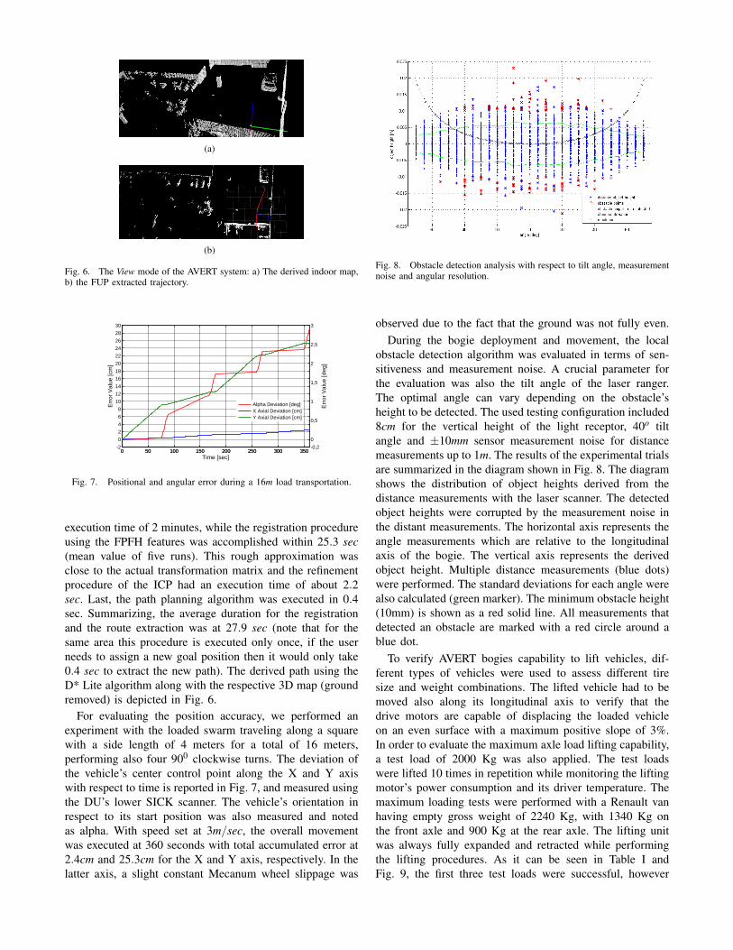
Fig. 8. Obstacle detection analysis with respect to tilt angle, measurementnoise and angular resolution.
observed due to the fact that the ground was not fully even.During the bogie deployment and movement, the local
obstacle detection algorithm was evaluated in terms of sen-sitiveness and measurement noise. A crucial parameter forthe evaluation was also the tilt angle of the laser ranger.The optimal angle can vary depending on the obstacle’sheight to be detected. The used testing configuration included8cm for the vertical height of the light receptor, 40o tiltangle and ±10mm sensor measurement noise for distancemeasurements up to 1m. The results of the experimental trialsare summarized in the diagram shown in Fig. 8. The diagramshows the distribution of object heights derived from thedistance measurements with the laser scanner. The detectedobject heights were corrupted by the measurement noise inthe distant measurements. The horizontal axis represents theangle measurements which are relative to the longitudinalaxis of the bogie. The vertical axis represents the derivedobject height. Multiple distance measurements (blue dots)were performed. The standard deviations for each angle werealso calculated (green marker). The minimum obstacle height(10mm) is shown as a red solid line. All measurements thatdetected an obstacle are marked with a red circle around ablue dot.
To verify AVERT bogies capability to lift vehicles, dif-ferent types of vehicles were used to assess different tiresize and weight combinations. The lifted vehicle had to bemoved also along its longitudinal axis to verify that thedrive motors are capable of displacing the loaded vehicleon an even surface with a maximum positive slope of 3%.In order to evaluate the maximum axle load lifting capability,a test load of 2000 Kg was also applied. The test loadswere lifted 10 times in repetition while monitoring the liftingmotor’s power consumption and its driver temperature. Themaximum loading tests were performed with a Renault vanhaving empty gross weight of 2240 Kg, with 1340 Kg onthe front axle and 900 Kg at the rear axle. The lifting unitwas always fully expanded and retracted while performingthe lifting procedures. As it can be seen in Table I andFig. 9, the first three test loads were successful, however
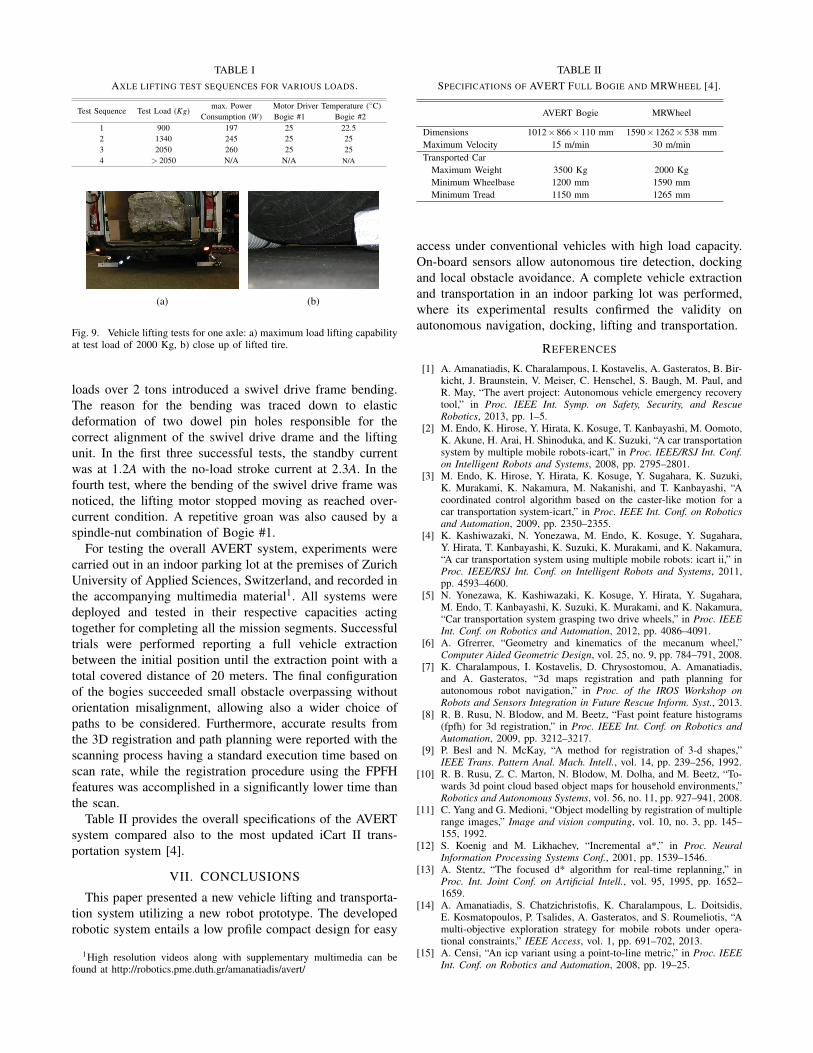
TABLE IAXLE LIFTING TEST SEQUENCES FOR VARIOUS LOADS.
Test Sequence Test Load (Kg)max. Power Motor Driver Temperature (◦C)
Consumption (W ) Bogie #1 Bogie #21 900 197 25 22.52 1340 245 25 253 2050 260 25 254 > 2050 N/A N/A N/A
(a) (b)
Fig. 9. Vehicle lifting tests for one axle: a) maximum load lifting capabilityat test load of 2000 Kg, b) close up of lifted tire.
loads over 2 tons introduced a swivel drive frame bending.The reason for the bending was traced down to elasticdeformation of two dowel pin holes responsible for thecorrect alignment of the swivel drive drame and the liftingunit. In the first three successful tests, the standby currentwas at 1.2A with the no-load stroke current at 2.3A. In thefourth test, where the bending of the swivel drive frame wasnoticed, the lifting motor stopped moving as reached over-current condition. A repetitive groan was also caused by aspindle-nut combination of Bogie #1.
For testing the overall AVERT system, experiments werecarried out in an indoor parking lot at the premises of ZurichUniversity of Applied Sciences, Switzerland, and recorded inthe accompanying multimedia material1. All systems weredeployed and tested in their respective capacities actingtogether for completing all the mission segments. Successfultrials were performed reporting a full vehicle extractionbetween the initial position until the extraction point with atotal covered distance of 20 meters. The final configurationof the bogies succeeded small obstacle overpassing withoutorientation misalignment, allowing also a wider choice ofpaths to be considered. Furthermore, accurate results fromthe 3D registration and path planning were reported with thescanning process having a standard execution time based onscan rate, while the registration procedure using the FPFHfeatures was accomplished in a significantly lower time thanthe scan.
Table II provides the overall specifications of the AVERTsystem compared also to the most updated iCart II trans-portation system [4].
VII. CONCLUSIONS
This paper presented a new vehicle lifting and transporta-tion system utilizing a new robot prototype. The developedrobotic system entails a low profile compact design for easy
1High resolution videos along with supplementary multimedia can befound at http://robotics.pme.duth.gr/amanatiadis/avert/
TABLE IISPECIFICATIONS OF AVERT FULL BOGIE AND MRWHEEL [4].
AVERT Bogie MRWheel
Dimensions 1012×866×110 mm 1590×1262×538 mmMaximum Velocity 15 m/min 30 m/minTransported Car
Maximum Weight 3500 Kg 2000 KgMinimum Wheelbase 1200 mm 1590 mmMinimum Tread 1150 mm 1265 mm
access under conventional vehicles with high load capacity.On-board sensors allow autonomous tire detection, dockingand local obstacle avoidance. A complete vehicle extractionand transportation in an indoor parking lot was performed,where its experimental results confirmed the validity onautonomous navigation, docking, lifting and transportation.
REFERENCES
[1] A. Amanatiadis, K. Charalampous, I. Kostavelis, A. Gasteratos, B. Bir-kicht, J. Braunstein, V. Meiser, C. Henschel, S. Baugh, M. Paul, andR. May, “The avert project: Autonomous vehicle emergency recoverytool,” in Proc. IEEE Int. Symp. on Safety, Security, and RescueRobotics, 2013, pp. 1–5.
[2] M. Endo, K. Hirose, Y. Hirata, K. Kosuge, T. Kanbayashi, M. Oomoto,K. Akune, H. Arai, H. Shinoduka, and K. Suzuki, “A car transportationsystem by multiple mobile robots-icart,” in Proc. IEEE/RSJ Int. Conf.on Intelligent Robots and Systems, 2008, pp. 2795–2801.
[3] M. Endo, K. Hirose, Y. Hirata, K. Kosuge, Y. Sugahara, K. Suzuki,K. Murakami, K. Nakamura, M. Nakanishi, and T. Kanbayashi, “Acoordinated control algorithm based on the caster-like motion for acar transportation system-icart,” in Proc. IEEE Int. Conf. on Roboticsand Automation, 2009, pp. 2350–2355.
[4] K. Kashiwazaki, N. Yonezawa, M. Endo, K. Kosuge, Y. Sugahara,Y. Hirata, T. Kanbayashi, K. Suzuki, K. Murakami, and K. Nakamura,“A car transportation system using multiple mobile robots: icart ii,” inProc. IEEE/RSJ Int. Conf. on Intelligent Robots and Systems, 2011,pp. 4593–4600.
[5] N. Yonezawa, K. Kashiwazaki, K. Kosuge, Y. Hirata, Y. Sugahara,M. Endo, T. Kanbayashi, K. Suzuki, K. Murakami, and K. Nakamura,“Car transportation system grasping two drive wheels,” in Proc. IEEEInt. Conf. on Robotics and Automation, 2012, pp. 4086–4091.
[6] A. Gfrerrer, “Geometry and kinematics of the mecanum wheel,”Computer Aided Geometric Design, vol. 25, no. 9, pp. 784–791, 2008.
[7] K. Charalampous, I. Kostavelis, D. Chrysostomou, A. Amanatiadis,and A. Gasteratos, “3d maps registration and path planning forautonomous robot navigation,” in Proc. of the IROS Workshop onRobots and Sensors Integration in Future Rescue Inform. Syst., 2013.
[8] R. B. Rusu, N. Blodow, and M. Beetz, “Fast point feature histograms(fpfh) for 3d registration,” in Proc. IEEE Int. Conf. on Robotics andAutomation, 2009, pp. 3212–3217.
[9] P. Besl and N. McKay, “A method for registration of 3-d shapes,”IEEE Trans. Pattern Anal. Mach. Intell., vol. 14, pp. 239–256, 1992.
[10] R. B. Rusu, Z. C. Marton, N. Blodow, M. Dolha, and M. Beetz, “To-wards 3d point cloud based object maps for household environments,”Robotics and Autonomous Systems, vol. 56, no. 11, pp. 927–941, 2008.
[11] C. Yang and G. Medioni, “Object modelling by registration of multiplerange images,” Image and vision computing, vol. 10, no. 3, pp. 145–155, 1992.
[12] S. Koenig and M. Likhachev, “Incremental a*,” in Proc. NeuralInformation Processing Systems Conf., 2001, pp. 1539–1546.
[13] A. Stentz, “The focused d* algorithm for real-time replanning,” inProc. Int. Joint Conf. on Artificial Intell., vol. 95, 1995, pp. 1652–1659.
[14] A. Amanatiadis, S. Chatzichristofis, K. Charalampous, L. Doitsidis,E. Kosmatopoulos, P. Tsalides, A. Gasteratos, and S. Roumeliotis, “Amulti-objective exploration strategy for mobile robots under opera-tional constraints,” IEEE Access, vol. 1, pp. 691–702, 2013.
[15] A. Censi, “An icp variant using a point-to-line metric,” in Proc. IEEEInt. Conf. on Robotics and Automation, 2008, pp. 19–25.