Embed Size (px)
Citation preview
Avi Vantage DocumentationRelease 17.1
Avi Networks
Mar 21, 2017

Contents:
1 Introduction 11.1 About Avi Vantage . . . . . . . . . . . . . . . . . . . . . . . . . . . . . . . . . . . . . . . . . . . . 1
2 Getting Started 32.1 Overview . . . . . . . . . . . . . . . . . . . . . . . . . . . . . . . . . . . . . . . . . . . . . . . . . 3
2.1.1 Avi Vantage Components . . . . . . . . . . . . . . . . . . . . . . . . . . . . . . . . . . . . 42.1.2 Data Plane Scaling . . . . . . . . . . . . . . . . . . . . . . . . . . . . . . . . . . . . . . . 5
2.2 Infrastructure . . . . . . . . . . . . . . . . . . . . . . . . . . . . . . . . . . . . . . . . . . . . . . . 62.3 System Requirements: Ecosystem . . . . . . . . . . . . . . . . . . . . . . . . . . . . . . . . . . . . 17
2.3.1 Hypervisor Support . . . . . . . . . . . . . . . . . . . . . . . . . . . . . . . . . . . . . . . 172.3.2 Bare Metal (Linux Server Cloud) . . . . . . . . . . . . . . . . . . . . . . . . . . . . . . . . 172.3.3 Orchestrator Support . . . . . . . . . . . . . . . . . . . . . . . . . . . . . . . . . . . . . . 172.3.4 SDN Solutions . . . . . . . . . . . . . . . . . . . . . . . . . . . . . . . . . . . . . . . . . 18
2.4 System Requirements: Hardware . . . . . . . . . . . . . . . . . . . . . . . . . . . . . . . . . . . . 182.5 Controller Cluster IP . . . . . . . . . . . . . . . . . . . . . . . . . . . . . . . . . . . . . . . . . . . 18
2.5.1 Cluster IP Advertisement . . . . . . . . . . . . . . . . . . . . . . . . . . . . . . . . . . . . 192.5.2 Configuring the Cluster IP . . . . . . . . . . . . . . . . . . . . . . . . . . . . . . . . . . . 19
2.6 Virtual Services . . . . . . . . . . . . . . . . . . . . . . . . . . . . . . . . . . . . . . . . . . . . . 192.6.1 Virtual Service Page . . . . . . . . . . . . . . . . . . . . . . . . . . . . . . . . . . . . . . 202.6.2 Virtual Services Details Pages . . . . . . . . . . . . . . . . . . . . . . . . . . . . . . . . . 22
2.7 Service Engine Group . . . . . . . . . . . . . . . . . . . . . . . . . . . . . . . . . . . . . . . . . . 232.7.1 BASIC SETTINGS TAB . . . . . . . . . . . . . . . . . . . . . . . . . . . . . . . . . . . . 242.7.2 ADVANCED TAB . . . . . . . . . . . . . . . . . . . . . . . . . . . . . . . . . . . . . . . 25
2.8 Pools . . . . . . . . . . . . . . . . . . . . . . . . . . . . . . . . . . . . . . . . . . . . . . . . . . . 272.8.1 What is a Pool? . . . . . . . . . . . . . . . . . . . . . . . . . . . . . . . . . . . . . . . . . 272.8.2 Pools Page . . . . . . . . . . . . . . . . . . . . . . . . . . . . . . . . . . . . . . . . . . . 272.8.3 Pool Details Page . . . . . . . . . . . . . . . . . . . . . . . . . . . . . . . . . . . . . . . . 28
3 Installation Guides 393.1 Amazon Web Services (AWS) . . . . . . . . . . . . . . . . . . . . . . . . . . . . . . . . . . . . . . 393.2 Cisco Application Policy Infrastructure (APIC) . . . . . . . . . . . . . . . . . . . . . . . . . . . . . 393.3 Cisco CSP 2100 . . . . . . . . . . . . . . . . . . . . . . . . . . . . . . . . . . . . . . . . . . . . . 393.4 Google Cloud Platform (GCP) . . . . . . . . . . . . . . . . . . . . . . . . . . . . . . . . . . . . . . 393.5 Linux Server Cloud (bare metal) . . . . . . . . . . . . . . . . . . . . . . . . . . . . . . . . . . . . . 393.6 Mesos / Marathon . . . . . . . . . . . . . . . . . . . . . . . . . . . . . . . . . . . . . . . . . . . . 393.7 OpenStack . . . . . . . . . . . . . . . . . . . . . . . . . . . . . . . . . . . . . . . . . . . . . . . . 393.8 Private cloud: Mesosphere DCOS (on-premises) . . . . . . . . . . . . . . . . . . . . . . . . . . . . 39
i

3.9 SDN Integration . . . . . . . . . . . . . . . . . . . . . . . . . . . . . . . . . . . . . . . . . . . . . 393.10 VMware vCenter . . . . . . . . . . . . . . . . . . . . . . . . . . . . . . . . . . . . . . . . . . . . . 39
4 Avi Integrations 414.1 Ansible Integration . . . . . . . . . . . . . . . . . . . . . . . . . . . . . . . . . . . . . . . . . . . . 41
4.1.1 Avi Controller Role . . . . . . . . . . . . . . . . . . . . . . . . . . . . . . . . . . . . . . . 414.1.2 Avi SE Role . . . . . . . . . . . . . . . . . . . . . . . . . . . . . . . . . . . . . . . . . . . 474.1.3 Avi Docker Role . . . . . . . . . . . . . . . . . . . . . . . . . . . . . . . . . . . . . . . . 474.1.4 Avi Network Interfaces Role . . . . . . . . . . . . . . . . . . . . . . . . . . . . . . . . . . 47
4.2 Python SDK Integration . . . . . . . . . . . . . . . . . . . . . . . . . . . . . . . . . . . . . . . . . 47
ii
CHAPTER 1
Introduction
About Avi Vantage
The Avi Vantage Platform delivers automated application services including load balancing, application analytics,predictive autoscaling, and security for on-premises or public cloud applications. The platform is built on software-defined principles, runs on commodity x86 servers, VMs, or containers, and matches the automation and self-servicegoals of modern enterprises.
The Avi Vantage Platform uses a software-defined architecture for application services to create a centrally managedpool of distributed load balancers which deliver services close to the applications. The platform brings public-cloud-like simplicity and flexibility to application services such as load balancing, application visibility and analytics, au-toscaling, and complete REST API-driven automation. Avi Vantage runs on any x86 servers (VM, bare metal, orcontainer) and scales up and down automatically in response to application traffic.
It features the capabilities:
• Full-featured software load balancers on any VM, bare metal server or container
• Single point of control for distributed load balancers
• Pinpoint analytics and visibility into application performance
• Predictive autoscaling of load balancers and applications
• REST APIs for all application services to automate services
1

Avi Vantage Documentation, Release 17.1
2 Chapter 1. Introduction
CHAPTER 2
Getting Started
Overview
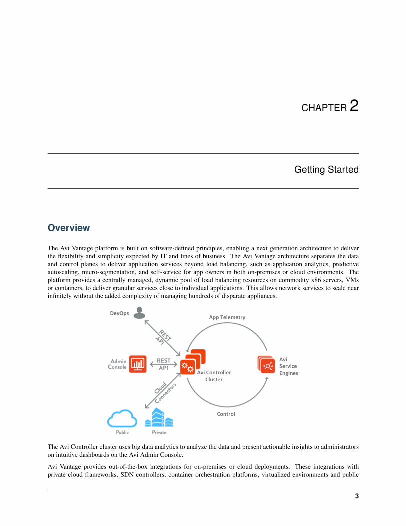
The Avi Vantage platform is built on software-defined principles, enabling a next generation architecture to deliverthe flexibility and simplicity expected by IT and lines of business. The Avi Vantage architecture separates the dataand control planes to deliver application services beyond load balancing, such as application analytics, predictiveautoscaling, micro-segmentation, and self-service for app owners in both on-premises or cloud environments. Theplatform provides a centrally managed, dynamic pool of load balancing resources on commodity x86 servers, VMsor containers, to deliver granular services close to individual applications. This allows network services to scale nearinfinitely without the added complexity of managing hundreds of disparate appliances.
The Avi Controller cluster uses big data analytics to analyze the data and present actionable insights to administratorson intuitive dashboards on the Avi Admin Console.
Avi Vantage provides out-of-the-box integrations for on-premises or cloud deployments. These integrations withprivate cloud frameworks, SDN controllers, container orchestration platforms, virtualized environments and public
3
Avi Vantage Documentation, Release 17.1
clouds enable turnkey application services and automation.
Avi Vantage Components
The Avi Vantage Platform has three core components – Avi Service Engines, Avi Controller cluster, and Avi AdminConsole:
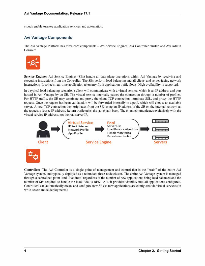
Service Engine: Avi Service Engines (SEs) handle all data plane operations within Avi Vantage by receiving andexecuting instructions from the Controller. The SEs perform load balancing and all client- and server-facing networkinteractions. It collects real-time application telemetry from application traffic flows. High availability is supported.
In a typical load balancing scenario, a client will communicate with a virtual service, which is an IP address and porthosted in Avi Vantage by an SE. The virtual service internally passes the connection through a number of profiles.For HTTP traffic, the SE may terminate and proxy the client TCP connection, terminate SSL, and proxy the HTTPrequest. Once the request has been validated, it will be forwarded internally to a pool, which will choose an availableserver. A new TCP connection then originates from the SE, using an IP address of the SE on the internal network asthe request’s source IP address. Return traffic takes the same path back. The client communicates exclusively with thevirtual service IP address, not the real server IP.
Controller: The Avi Controller is a single point of management and control that is the “brain” of the entire AviVantage system, and typically deployed as a redundant three-node cluster. The entire Avi Vantage system is managedthrough a centralized point (and IP address) regardless of the number of new applications being load balanced and thenumber of SEs required to handle the load. Via its REST API, it provides visibility into all applications configured.Controllers can automatically create and configure new SEs as new applications are configured via virtual services (inwrite access mode deployments).
4 Chapter 2. Getting Started
Avi Vantage Documentation, Release 17.1
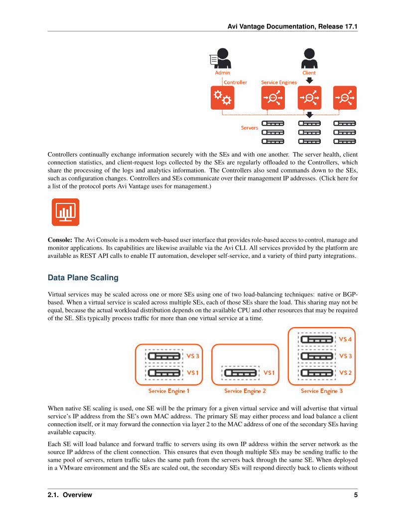
Controllers continually exchange information securely with the SEs and with one another. The server health, clientconnection statistics, and client-request logs collected by the SEs are regularly offloaded to the Controllers, whichshare the processing of the logs and analytics information. The Controllers also send commands down to the SEs,such as configuration changes. Controllers and SEs communicate over their management IP addresses. (Click here fora list of the protocol ports Avi Vantage uses for management.)
Console: The Avi Console is a modern web-based user interface that provides role-based access to control, manage andmonitor applications. Its capabilities are likewise available via the Avi CLI. All services provided by the platform areavailable as REST API calls to enable IT automation, developer self-service, and a variety of third party integrations.
Data Plane Scaling
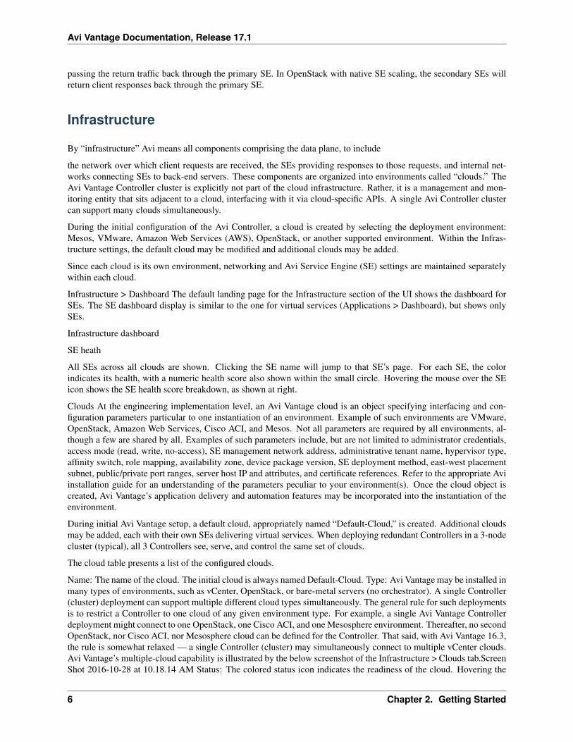
Virtual services may be scaled across one or more SEs using one of two load-balancing techniques: native or BGP-based. When a virtual service is scaled across multiple SEs, each of those SEs share the load. This sharing may not beequal, because the actual workload distribution depends on the available CPU and other resources that may be requiredof the SE. SEs typically process traffic for more than one virtual service at a time.
When native SE scaling is used, one SE will be the primary for a given virtual service and will advertise that virtualservice’s IP address from the SE’s own MAC address. The primary SE may either process and load balance a clientconnection itself, or it may forward the connection via layer 2 to the MAC address of one of the secondary SEs havingavailable capacity.
Each SE will load balance and forward traffic to servers using its own IP address within the server network as thesource IP address of the client connection. This ensures that even though multiple SEs may be sending traffic to thesame pool of servers, return traffic takes the same path from the servers back through the same SE. When deployedin a VMware environment and the SEs are scaled out, the secondary SEs will respond directly back to clients without
2.1. Overview 5
Avi Vantage Documentation, Release 17.1
passing the return traffic back through the primary SE. In OpenStack with native SE scaling, the secondary SEs willreturn client responses back through the primary SE.
Infrastructure
By “infrastructure” Avi means all components comprising the data plane, to include
the network over which client requests are received, the SEs providing responses to those requests, and internal net-works connecting SEs to back-end servers. These components are organized into environments called “clouds.” TheAvi Vantage Controller cluster is explicitly not part of the cloud infrastructure. Rather, it is a management and mon-itoring entity that sits adjacent to a cloud, interfacing with it via cloud-specific APIs. A single Avi Controller clustercan support many clouds simultaneously.
During the initial configuration of the Avi Controller, a cloud is created by selecting the deployment environment:Mesos, VMware, Amazon Web Services (AWS), OpenStack, or another supported environment. Within the Infras-tructure settings, the default cloud may be modified and additional clouds may be added.
Since each cloud is its own environment, networking and Avi Service Engine (SE) settings are maintained separatelywithin each cloud.
Infrastructure > Dashboard The default landing page for the Infrastructure section of the UI shows the dashboard forSEs. The SE dashboard display is similar to the one for virtual services (Applications > Dashboard), but shows onlySEs.
Infrastructure dashboard
SE heath
All SEs across all clouds are shown. Clicking the SE name will jump to that SE’s page. For each SE, the colorindicates its health, with a numeric health score also shown within the small circle. Hovering the mouse over the SEicon shows the SE health score breakdown, as shown at right.
Clouds At the engineering implementation level, an Avi Vantage cloud is an object specifying interfacing and con-figuration parameters particular to one instantiation of an environment. Example of such environments are VMware,OpenStack, Amazon Web Services, Cisco ACI, and Mesos. Not all parameters are required by all environments, al-though a few are shared by all. Examples of such parameters include, but are not limited to administrator credentials,access mode (read, write, no-access), SE management network address, administrative tenant name, hypervisor type,affinity switch, role mapping, availability zone, device package version, SE deployment method, east-west placementsubnet, public/private port ranges, server host IP and attributes, and certificate references. Refer to the appropriate Aviinstallation guide for an understanding of the parameters peculiar to your environment(s). Once the cloud object iscreated, Avi Vantage’s application delivery and automation features may be incorporated into the instantiation of theenvironment.
During initial Avi Vantage setup, a default cloud, appropriately named “Default-Cloud,” is created. Additional cloudsmay be added, each with their own SEs delivering virtual services. When deploying redundant Controllers in a 3-nodecluster (typical), all 3 Controllers see, serve, and control the same set of clouds.
The cloud table presents a list of the configured clouds.
Name: The name of the cloud. The initial cloud is always named Default-Cloud. Type: Avi Vantage may be installed inmany types of environments, such as vCenter, OpenStack, or bare-metal servers (no orchestrator). A single Controller(cluster) deployment can support multiple different cloud types simultaneously. The general rule for such deploymentsis to restrict a Controller to one cloud of any given environment type. For example, a single Avi Vantage Controllerdeployment might connect to one OpenStack, one Cisco ACI, and one Mesosphere environment. Thereafter, no secondOpenStack, nor Cisco ACI, nor Mesosphere cloud can be defined for the Controller. That said, with Avi Vantage 16.3,the rule is somewhat relaxed — a single Controller (cluster) may simultaneously connect to multiple vCenter clouds.Avi Vantage’s multiple-cloud capability is illustrated by the below screenshot of the Infrastructure > Clouds tab.ScreenShot 2016-10-28 at 10.18.14 AM Status: The colored status icon indicates the readiness of the cloud. Hovering the
6 Chapter 2. Getting Started
Avi Vantage Documentation, Release 17.1
mouse over the icon provides more information about the status, such as ready for use or incomplete configuration.Additional Icons: The far right column of the table has a number of additional icons. The exact icons shown willdepend on the clouds configured and their status. Edit: Open the edit modal for the cloud. Convert: Convert thecloud from read access mode or write access mode to no access mode. When in no access mode, Avi Controllers donot have access to the cloud’s orchestrator, such as vCenter. See the installation documentation for the orchestratorto see the full implications of no access mode. Expand: Click the plus icon or anywhere within the table row toexpand the row and show more information about the cloud. For instance, in AWS the Region, Availability Zone, andNetworks are shown. Download SE Image: When Avi Vantage is deployed in read access mode or no access mode,SEs must be installed manually. Use this button to pull the SE image for the appropriate image type (ova or qcow2).The SE image will have the Controller’s IP or cluster IP address embedded within it, so an SE image may only beused for the Avi Vantage deployment that created it. Generate Token: Authentication tokens are used for securingcommunication between Controllers and SEs. If Avi Vantage is deployed in read access mode or no access mode,the SE authentication tokens must be copied manually by the Avi Vantage user from the Controller web interface tothe cloud orchestrator. For example, in a VMware deployment, the OVF template deployment dialog requires theController’s authentication token as one of the input values.If needed for your read access mode or no access modedeployment, click this icon to display the Controller’s authentication token, then copy-and-paste the token into theappropriate field in the cloud orchestrator interface. (See the Avi Vantage installation guide for your infrastructuretype for details.) Install LBaaS Plugin: For OpenStack clouds, this icon opens the LBaaS plugin dialog. Input theinformation regarding the Neutron server to install the plugin. Avi Vantage will automatically push the LBaaS packageto Neutron. If other considerations prevent using this method to install the plugin, such as requiring an SSH key insteadof a Neutron password, then manually install by downloading the plugin from avinetworks.com/portal.
Cloud Creation An initial cloud is created by default when Avi Vantage is first deployed, and is documented in theInstallation Guide for the appropriate cloud environment. To add an additional cloud, click the green New button toadd the new cloud to the Avi Vantage deployment.
Select the desired cloud. When deploying Avi SEs on bare metal servers, select No Orchestrator. This step is for thevirtualization infrastructure and orchestrator. Supported network SDN technologies such as Cisco ACI or Nuage maybe configured as additional properties of the cloud for which they are supported.
inf_cloud_create-withmesos
Cloud Management Clicking on the name of a cloud allows configuration of infrastructure objects within the environ-ment. Each of these objects are specific to this cloud. For instance, a default static route configured in cloud 1 is onlyapplicable to SEs in that cloud, and will not affect SEs in another cloud.
Service Engines Avi Service Engines (SEs) handle all of the data plane operations within Avi Vantage. SEs host thevirtual services and require either direct or routable access to all client and server networks a virtual service touches.
A typical Avi Vantage deployment may have many SEs for various purposes, such as redundancy, scalability, andaccommodating large numbers of applications being served. SEs are always grouped within the context of a SE group,which provides settings for high availability, scalability, and potentially resource isolation for tenants.
Service Engines Page › Service Engine Quick Info Popup › Create a Service Engine › Delete a Service Engine ›
Service Engines Page
The Service Engines page lists the SEs that are currently configured in Avi Vantage.
se-list
To display the SE list for a cloud, select Infrastructure > Clouds, click on a cloud name, and click Service Engines.
This page includes the following functions:
Search: Search through the list of object names. Edit: Opens the Edit Service Engine popup. This page contains thefollowing information for each SE in the selected cloud:
Name: Lists the name of each SE. Clicking the name of an SE opens the Analytics tab of the Service Engine Detailspage. Health: Provides both a numeric health score from 1-100 and a color-coded status to provide quick informationabout the health of the SE. Hovering the cursor over the score opens the Health Score popup for the SE. The View
2.2. Infrastructure 7

Avi Vantage Documentation, Release 17.1
Health link at the bottom of the popup opens the Health tab of the Service Engine Details page. Clicking within theHealth Score opens the Analytics tab of the Service Engine Details page. Note: Clicking on blank space in the ServiceEngine row will expand the row to show the list of virtual services assigned this this SE.
Service Engines Details Page
The Service Engine Details page shows information about the currently selected SE.
se-details-drilleddown
This page contains the following popup and tabs:
Quick Info Popup › Analytics Tab › Health Tab › Events Tab › Alerts Tab ›
Service Engine Quick Info
Hovering over or clicking the name of the SE in the top left corner of the Service Engine Details page opens theService Engine Info popup for that SE.
se-details-hoverover
This popup provides the following information for the SE:
Management IP: IP address the SE uses to communicate with the Controller. Uptime: The amount of time in daysand hours that the SE has been either active or down. Management Interface: Network interface being used to allowthe SE to communicate with the Controller. This address is reserved for management, and is not used for data planeor load balanced traffic. If management and data plane traffic will share the same network, they will still use twoseparate network interfaces and IP addresses. Management Network: Network used by the SE to communicate withthe Controller. This may be the same network as one of the data networks used for load balancing. Best practice isto utilize a separate, dedicated network for control plane communications. Service Engine group: SE group that thisSE belongs to. If you did not create an SE group, or the virtual service was not assigned to a unique SE group, thena new SE will default to the Default SE group. Physical Host: IP address of the physical server hosting the virtualmachine on which the SE is running. System Memory: Amount of used versus available memory. Memory utilizationshould not exceed 90% for an extended period of time. Disk Usage: Percentage of allocated storage space being usedby the SE. By default, an SE will be allocated 10 GB of storage. As the storage becomes full, logs may be purgedprior to indexing. Adding more storage to a SE allows a greater volume of logs to be stored. Number of CPUs:Number of virtual CPU cores allocated to the SE. An idle SE will still consume some CPU as it is running normalhousekeeping processes. An SE should not exceed 90% for an extended period of time as it may introduce latency inclient transactions.
Service Engine Analytics
The Analytics tab presents information about various performance metrics over the time period selected.
Service Engine Analytics: Metrics
The following metrics are available for SEs:
Throughput: Total bandwidth flowing through the SE for all virtual services being hosted by that SE. This includesthe bandwidth flowing in and out of the SE between the client and the virtual service, and the traffic between the SEand the servers. Thus, an SE may report approximately double the throughput of its virtual services.
CPU Usage: Displays the utilization of the CPUs allocated to the SE. The total number of CPUs appears in the ServiceEngine Quick Info Popup. Under normal conditions, CPU usage should not regularly exceed 90%, as this may causelatency in the virtual services and disrupt the client experience. The CPU Usage metric tile shows a horizontal barindicating current usage, with a red line at the right to indicate how close the SE is to pushing the limits of its availableCPU capacity.You may indirectly control or improve CPU usage by taking actions, such as: Configuration: Changingthe configuration of virtual services, such as changing SSL or compression settings, will impact the CPU usage. CPUAllocation: Allocating more vCPUs per SE. The default setting is two vCPUs per SE. Increasing this number isparticularly useful for tasks such as SSL termination or compression which heavily consume CPU resources. Thesetting for the number of vCPUs assigned to an SE is in the SE group. Scale Out: Reduce the CPU load by scalingthis SE’s virtual services across additional SEs, which will increase the total capacity and reduce the load on this SE.
8 Chapter 2. Getting Started
Avi Vantage Documentation, Release 17.1
The high availability setting of the SE group dictates when a virtual service should be scaled out across additional SEsor simply migrated away from a busy SE. CPU Reservation: By default, CPUs resource is not reserved in a VMwaredeployment. Within vCenter, you may enable reservation for the SE’s virtual machine, which guarantees that othervirtual machines sharing the same physical host server will not be able to borrow or compete for CPU resources. Thissetting may be changed in the SE group properties. Changes will take effect for new SEs only. To make this changefor existing SEs, it must be manually changed within vCenter. Refer to your VMware documentation.
Interface Throughput: Shows the combined throughput for all network interfaces utilized by this SE. Throughput ismeasured as both client and server side of any virtual services, plus the management traffic between the SE and theControllers.
Virtual Service Throughput: Shows the combined throughput for all network interfaces utilized by this SE. Throughputis measured as both client and server side of any virtual services, plus the management traffic between the SE and theControllers. Service Engine Analytics: Chart Pane
The main chart pane in the middle of the Analytics tab displays a detailed historical chart of the selected Metric tilefor the current virtual service, pool, or SE.
Hovering the mouse over any point in the chart will display the results for that selected time in a popup window.Clicking within the chart will freeze the popup at that point in time. This may be useful when the chart is scrolling asthe display updates over time. Clicking again will unfreeze the highlighted point in time.
Many charts contain radio buttons in the top right that allow you to customize which data should be excluded from thechart. For example, if the End to End Timing chart is heavily skewed by one very large metric, then deselecting thatmetric by clearing the appropriate radio button will re-factor the chart based on the remaining metrics shown. Thismay change the value of the vertical Y-axis.
Some charts also contain overlay items, which will appear as color-coded icons along the bottom of the chart.
Service Engine Analytics: Overlays Pane
The overlays pane allows you to overlay icons signifying important events within the timeline of the chart pane. Thisfeature helps you correlate anomalies, alerts, configuration changes, and system events with changes in traffic patterns.
Within the overlays pane:
Each overlay type displays the number of entries for the selected time period. Clicking an overlay button toggles thatoverlay’s icons in the chart pane. The button lists the number of instances (if any) of that event type within the selectedtime period. Selecting an overlay button displays the icon for the selected event type along the bottom of the chart pane.Multiple overlay icon types may overlap. Clicking the overlay type’s icon in the chart pane will bring up additionaldata below the Overlay Items bar. The following overlay types are available: Anomalies: Display anomalous trafficevents, such as a spike in server response time, along with corresponding metrics collected during that time period.Alerts: Display alerts, which are filtered system-level events that have been deemed important enough to notify anadministrator. Config Events: Display configuration events, which track configuration changes made to Avi Vantageby either an administrator or an automated process. System Events: Display system events, which are raw data pointsor metrics of interest. System events can be noisy, and are best used by alerts which filter and classify these raw eventsby severity. SE Analytics: Anomalies Overlay
The Anomalies overlay displays periods during which traffic behavior was considered abnormal based on recent his-torical moving averages. Changing the time interval will provide greater granularity and potentially show more anoma-lies. Clicking the Anomalies Overlay button displays yellow anomaly icons in the chart pane, which can scroll downto view additional information related to that anomaly. During times of anomalous traffic, Avi Vantage records anymetrics that have deviated from the norm, which may provide hints as to the root cause of the anomaly.
Note: An anomaly is defined as a metric that has a deviation of 4 sigma or greater across the moving average of thechart.
Note: Anomalies are not recorded or displayed in the real time mode. These metrics are defined as follows:
Timestamp: Date and time when the anomaly was detected. This may either span the full duration of the anomaly, ormerely be near the same time window. Type: The specific metric deviating from the norm during the anomaly period.
2.2. Infrastructure 9

Avi Vantage Documentation, Release 17.1
To be included, the metric deviation must be greater than 4 sigma. Numerous types of metrics, such as CPU utilization,bandwidth, or disk I/O may trigger anomalous events. Entity: Name of the specific object that is reporting this metric.Entity Type: Type of entity that caused the anomaly. This may be one of the following: Virtual Machine (server); thesemetrics require Avi Vantage to be configured for either read or write access to the virtualization orchestrator such asvCenter or OpenStack. In the example above, CPU utilization of the two servers was learned by querying vCenter.Virtual service SE Time Series: Thumbnail historical graph for the selected metric, including the most current valuefor the metric which will be data on the far right. Moving the mouse over the chart pane will show the value of themetric for the selected time. Use this to compare the normal, current, and anomaly time periods. Deviation: Changeor deviation from the moving average, either higher or lower. The time window for the moving average depends onthe time series selected for the Analytics tab. SE Analytics: Alerts Overlay
The Alerts overlay displays the results of any events that meet the filtering criteria defined in the Alerts tab. Alertsnotify administrators about important information or changes to a site that may require immediate attention.
Alerts may be transitory, meaning they may expire after a defined period of time. For instance, Avi Vantage maygenerate an alert if a server is down and then allow that alert to expire after a specified time period once the servercomes back online. The original event remains available for later troubleshooting purposes.
Clicking the Alerts icon in the Overlay Items bar displays any red Alerts icons in the chart Pane. Selecting one ofthese chart alerts will bring up additional information below the Overlay Items bar, which will show the followinginformation:
Timestamp: Date and time when the Alert occurred. Resource Name: Name of the object that is reporting the Alert.Level: Severity of the Alert. You can use the priority level to determine whether additional notifications should occur,such as sending an email to administrators or sending a log to Syslog servers. The level may be one of the following:High: Red Medium: Yellow Low: Blue Summary: Brief description of the event. Actions: Dismiss the Alert with thered X to remove it from both the list shown and the Alert icon the chart pane. Dismissing an Alert here is the sameas dismissing it via the bell icon at the top of the screen next to the Health Score, or dismissing it via the Alerts tab.Edit the Alert filter to make Avi Vantage more or less sensitive to generating new alerts. Expand/Contract: Clickingthe plus (+) or minus sign (-) for an Alert opens and closes a sub-table showing more detail about the Alert. This willtypically show the original events that triggered the alert. SE Analytics: Config Events Overlay
The Config Events overlay displays configuration events, such as changing the Avi Vantage configuration by adding,deleting, or modifying a pool, virtual service, or SE, or an object related to the object being inspected. If trafficdropped off at precisely 10:00 a.m., and at that time an administrator made a change to the virtual services securitysettings, there’s a good chance the cause of the change in traffic was due to the (mis)configuration.
Clicking the Config Events icon in the Overlay Items bar displays any blue Config Event icons in the chart pane.Selecting one of these chart alerts will bring up additional information below the Overlay Items bar, which will showthe following information:
Timestamp: Date and time when the configuration change occurred. Event Type: Always be scoped to Configura-tion event types. Resource Name: Name of the object that has been modified. Event Code: There are three eventcodes: CONFIG_CREATE CONFIG_UPDATE CONFIG_DELETE Description: Brief description of the event. Ex-pand/Contract: Clicking the plus (+) or minus sign (-) for a configuration event either expands or contracts a sub-tableshowing more detail about the event. When expanded, this shows a difference comparison of the previous configura-tion versus the new configuration, as follows: Additions to the configuration, such as adding a health monitor, will behighlighted in green in the new configuration. Removing a setting will be highlighted in red in the previous config-uration. Changing an existing setting will be highlighted in yellow in both the previous and new configurations. SEAnalytics: System Events Overlay
This overlay displays System Events relevant to the current object, such as a server changing status from up to downor the health score of a virtual service changing from 50 to 100.
Clicking the System Events icon in the Overlay Items bar displays any purple System Event icons in the chart pane.Select a system event icon in the chart pane to bring up more information below the Overlay Items bar.
Timestamp: Date and time when the system even occurred. Event Type: This will always be System. Resource Name:Name of the object that triggered the event. Event Code: High-level definition of the event, such as VS_Health_Change
10 Chapter 2. Getting Started
Avi Vantage Documentation, Release 17.1
or VS_Up. Description: Brief description of the system event. Expand/Contract: Clicking the plus (+) or minus sign(-) for a system event expands or contracts that system event to show more information.
Service Engine Health
The health score of an on object is comprised from the following scores:
Performance: Performance score (1-100) for the selected item. A score of 100 is ideal, meaning clients are notreceiving errors and connections or requests are quickly returned. Resource Penalty: Any penalty assessed becauseof resource availability issues is assigned a score, which is then subtracted from the Performance score. A score of0 is ideal, meaning there are no obvious resource constraints on Avi Vantage or virtualization orchestrator connectedservers. Anomaly Penalty: Any penalty assessed because of anomalous events is assigned a score, which is thensubtracted from the Performance score. An ideal score is 0, which means Avi Vantage has not seen recent anomaloustraffic patterns that may imply future risk to the site. Health Score: The final health score for the selected item equalsthe Performance Score minus the Resource and Anomaly Penalty scores. The sidebar tiles show the scores of each ofthe three subcomponents of the health score, plus the total score. To determine why an object such as a virtual servicehas a low health score, select one of the first three tiles that is showing a subpar score.
This will bring up additional sub-components for the top level metric, such as pools, connection Apdex, ResponseApdex, or others. Again, select the tile that is showing the worst score. Some tiles may have additional informationshown in the main chart section that requires scrolling down to view. Clicking on a tile for another object such as apool or SE will jump to the Insights page for that object.
The chart pane of the tab shows a detailed graph of the selected score:
Clicking any of the summary Metrics tiles on the sidebar displays the detailed version of that graph in the chart paneof the tab. Additional details may display at the bottom of the tab that show various factors contributing to that score.Hovering your mouse cursor over any of the charts displays the health score for the selected date and time on allgraphs.
Service Engine Events
The Events tab presents system-generated events over the time period selected for the SE. System events are applicableto the context in which you are viewing them. For example, when viewing events for a SE, only events that are relevantto that object are displayed.
se-details-events
The top of this tab displays the following items:
Search: The Search field allows you to filter the events using whole words contained within the individual events.Refresh: Clicking Refresh updates the events displayed for the currently-selected time. Number: The total number ofevents being displayed. The date/time range of those events appear beneath the Search field on the left. Clear Selected:If filters have been added to the Search field, clicking the Clear Selected (X) icon on the right side of the search barwill remove those filters. Each active search filter will also contain an X that you can click to remove the specificfilter. Histogram: The Histogram shows the number of events over the period of time selected. The X-axis is time,while the Y-axis is the number of events during that bar’s period of time. Hovering the cursor over a Histogram bardisplays the number of entries represented by that bar, or period of time. Click and drag inside the histogram to refinethe date/time period which further filters the events shown. When drilling in on the time in the Histogram, a Zoom toselected link appears above the Histogram. This expands the drilled in time to expand to the width of the Histogram,and also changes the Displaying pull-down menu to Custom. To return to the previously selected time period, use theDisplay pull-down menu. The table at the bottom of the Events tab displays the events that matched the current timewindow and any potential filters. The following information appears for each event:
Timestamp: Date and time the event occurred. Highlighting a section of the histogram allows further filtering of eventswithin a smaller time window. Event Type: This may be one of the following: System: System events are generatedby Avi Vantage to indicate a potential issue or create an informational record, such as VS_Down. Configuration:Configuration events track changes to the Avi Vantage configuration. These changes may be made by an administrator(through the CLI, API, or GUI), or by automated policies. Resource Name: Name of the object related to the event,such as the pool, virtual service, SE, or Controller. Event Code: A short event definition, such as Config_Action or
2.2. Infrastructure 11
Avi Vantage Documentation, Release 17.1
Server_Down. Description: A complete event definition. For configuration events, the description will also showthe username that made the change. Expand/Contract: Clicking the plus (+) or minus sign (-) for an event log eitherexpands or contracts that event log. Clicking the + and – icons in the table header expands and collapses all entriesin this tab. For configuration events, expanding the event displays a difference comparison between the previous andnew configurations.
New fields will appear highlighted in green in the new configuration Removed fields will appear highlighted in red.Changed fields will show highlighted in yellow.
Service Engine Alerts
The Alerts tab displays specified events that have trigger an alert. Alert actions can be configured, and proactivenotifications generated via Syslog or email in the Notifications tab of the Administration page. Alerts act as filtersthat provide notification for prioritized events or combinations of events through various mechanisms such as the AviVantage web interface, email, or Syslog. Avi Vantage includes a number of default alerts based on events deemed tobe universally important.
The top of this tab shows the following items:
Search: The Search field allows you to filter the alerts using whole words contained within the individual alerts.Refresh: Clicking Refresh updates the alerts displayed for the currently-selected time. Number: The total number ofalerts being displayed. The date/time range of those alerts appear beneath the Search field on the left. Dismiss: Selectone or more alerts from the table below then click Dismiss to remove the alert from the list. Note: Alerts are transitory,meaning they will eventually and automatically expire. Their intent is to notify an administrator of an issue, ratherthan being the definitive record for issues. Alerts are based on events, and the parent event will still be in the eventsrecord. The table at the bottom of the Alerts tab displays the following alert details:
Timestamp: Date and time when the alert was triggered. Changing the time interval using the Displaying pull-downmenu may potentially show more alerts. Resource Name: Name of the object that is the subject of the alert, such as aServer or virtual service. Level: Severity level of the alert, which can be High, Medium, or Low. Specific notificationscan be set up for the different levels of alerts via the Administration page’s Alerts Overlay. Summary: Summarizeddescription of the alert. Action: Click the appropriate button to act on the alert: Dismiss: Clicking the red X dismissesthe alert and removes it from the list of displayed alerts. Edit: Clicking the blue pencil icon opens the Edit Alert Configpopup for the alert configuration that triggered this alert. This can include a verbose and customized description of thealert or allow an administrator to alter settings such as the severity of the alert. Expand/Contract: Clicking the plus (+)or minus sign (-) for an event log either expands or contracts that event log to display more information. Clicking the+ and – icon in the table header expands and collapses all entries in this tab
Service Engine Create: Write Access Mode Deployments
An Avi Controller that is deployed in write access mode has full write access to the virtualization platform and canautomatically deploy new SEs and modify the network configuration of existing SEs. The Controller will place thevirtual service on a SE within a cluster and host that has optimal reachability to the servers. In a new Avi Vantagedeployment, the first SE will not be created until the first virtual service is created, as this is required to know whichserver network will be used.
The health score of a newly created virtual service will appear as gray with an exclamation point while the SE is beingcreated; hovering the mouse over the health score will show the status as Creating. During this time, the Controllercopies the SE image file from itself to the host server, sets up virtual machine settings via the virtualization orchestrator,then sets the network adapters and IP addresses required to reach clients and servers. This process may take anywherefrom a few seconds to a few minutes, depending on the time it takes to copy the SE image across the network to aphysical host. If creation of the SE fails, the Controller will wait for five minutes and then attempt to recreate the SEon a new host.
In an established environment, a new virtual service may use an existing SE and thus be brought up immediately.Preferences for high availability, scalability, and number of virtual services per SE are defined within the SE groupsettings.
12 Chapter 2. Getting Started

Avi Vantage Documentation, Release 17.1
If all virtual services for a SE are deleted and the SE is no longer in use, the Controller will wait 120 minutes beforeautomatically removing the unused SE. This setting may be configured via the SE group properties.
Service Engine Create: Read/No Access Mode Deployments
When Avi Vantage is deployed in read access mode or no access mode, Avi Vantage does not have write access to thevirtualization infrastructure. In this case, an administrator must manually perform any operations that require writeaccess to the virtualization environment (create and delete SEs and configure network settings).
A new virtual service may be able to use an existing SE, though it may still require an administrator to change thenetwork settings such as adding a new network interface into a port group required for access to servers.
Creating a new SE when the Avi Controller has Read or no access to the virtualization platform is almost identical tothe process described in the Installation Guide for your selected virtualization platform, except that:
If the data plane network interfaces (those processing load balanced traffic) need to be set to a static IP address, anadministrator will need to manually match the network interface shown in the Avi Controller with the Network Adaptershown in the virtualization platform. The Controller cannot poll the Network Name because it does not have accessto the virtualization platform. An admin will need to find the MAC Address of the virtual machine’s network adapterthat clients wish to use, and then correspond that to the MAC Address shown in the Edit a Service Engine popup. Edita Service Engine
The Edit Service Engine popup allows an administrator to modify the network settings for the SE. To edit an SE, selectInfrastructure > Service Engines and click on the SE name or on the edit icon.
se-edit
Note: Properties such as hardware resources and VLAN placement are configured within the SE group. Many net-working properties can be configured on the Networks tab and in the Service Engine Edit popup. Editing the SEproperties will only affect the specific SE being modified; you will need to manually modify any new SE createdthereafter. If Avi Vantage has No access to the hypervisor, the administrator will need to manually edit the networkand IP settings for each SE. For deployments in write access mode, editing the values on the Network tab is needed toensure that any new SE will inherit the desired settings.
Service Engine Group: An SE may be manually migrated to a different SE group by selecting the new SE group fromthe dropdown menu. Moving a SE is not graceful. It will first terminate any existing connections. DHCP: DHCP maybe enabled per network interface, not per IP network. This is the default setting for all network interfaces. An SEattempting to use DHCP to acquire an IP address will retry every five minutes and will generate an error in the eventslog if it is unsuccessful.Note: A single interface may have multiple networks configured. It is therefore possible tohave both DHCP and static IP addresses configured for a single interface. Default Gateway: Enter a new IP addressfor the gateway in the Default Gateway field.
Delete a Service Engine
An SE may be deleted for many reasons, such as:
Placement on a different physical host. Updating resource sizes (e.g., number of vCPUs) Reduced load no longerrequires as many SEs. If Vantage is deployed to have write access mode to the hypervisor orchestrator, Avi Vantagewill automatically delete unused SEs. If Avi Vantage is deployed in read access mode or no access mode, SEs may bedeleted from the Controller, but it will still require an administrator to manually delete the SE from the virtualizationplatform.
Note: To delete an SE from a Controller immediately rather than wait for the SE to time out based on the SE groupsettings, use the CLI or API.
Service Engine Group An SE group is a collection of one or more SEs that may share properties, such as networkaccess and failover. An SE cannot scale out across or fail over to an SE which is in a different SE group, even if bothSEs share the same physical host or network properties. Different applications can thus receive guaranteed data planeisolation when deployed on different SE groups.
2.2. Infrastructure 13

Avi Vantage Documentation, Release 17.1
Virtual services created in a newAvi Vantage deployment will be assigned to the Default-Group SE group. To deployvirtual services to a different SE group:
Create a new SE group. Move or create the new virtual service in the new group using the Advanced tab of the EditVirtual Service page. When creating a new SE group in write access mode, no new SEs will be created until a virtualservice is deployed to the SE group. In read access mode or no access mode deployments, the new SEs must bemanually created. They will attempt to connect back to the Controller after they have booted up, at which point theywill be added to the Default SE group. SEs in read access mode and no access mode deployments can be migrated toa new SE group, provided all virtual services deployed on the SE are disabled.
SEs in write access mode deployments cannot be migrated to new SE groups. Instead, the old SE is deleted and a newSE is created. This process is automatic if the virtual services are migrated.
Service Engine Groups Page
The Service Engine Groups page lists the configured SE groupsScreen Shot 2016-07-08 at 3.25.20 PM
The table on this page contains the following information for each SE group:
Name: Lists the name of each SE group. # Service Engines: Shows the number of SEs assigned to the SE group. Ifthe value is non-zero, clicking the row on the table will show an expanded view with the names of SEs. MaximumNumber of Service Engines: Maximum number of SEs the group can contain. # Virtual Services: Shows the numberof virtual services currently assigned to the SE group. If the value is non-zero, clicking the row on the table will showan expanded view with the names of virtual services. HA Mode: High availability mode configured for the group. Todelete an SE group, click the box at the far left of its row. A Delete button will appear. Click Delete to delete the SEgroups whose rows have been checked.
Note: Only unused SE groups may deleted. If the SE group is in use by a virtual service, a popup will warn thatdependent virtual services must first be deleted or migrated to other SE groups via the Virtual Service > Edit >Advanced properties tab. A tenant must always have a minimum of one configured SE group. The default SE groupmay be modified, but not deleted.
Create a Service Engine Group
To create or edit an SE group:
Select Infrastructure > Clouds and click on the cloud name (for example, Default-Cloud). Select Service Engine Groupto open the Service Engine Groups page, which lists the SE groups currently configured in Avi Vantage. Click NewService Engine Group or click on an SE group name in the table. The create and edit popups for SE groups haveidentical properties. This popup includes the following tabs:
Basic Settings Tab Advanced Tab Basic Settings Tab
Click New in the Edit Service Engine Group popup to open the High Availability tab.
Edit the High Availability settings:
Name: Enter a unique name for the SE group in the Name field. Optionally configure any setting within the HighAvailability tab. Either click the Advanced Tab, or Save to return to the Service Engine Groups page. High AvailabilitySettings
The availability of a virtual service after an SE failure is governed by settings set at the SE group level.
Screen Shot 2016-07-08 at 3.45.41 PM
To gain an understanding of the three HA modes defined by Avi Vantage, refer to these articles:
Legacy HA Elastic HA Service Engine Capacity and Limit Settings
se-group-limit-settings
Number of Service Engines: defines the maximum SEs that may be created within a SE group. This number, combinedwith the virtual services per SE setting, dictate the maximum number of virtual services that can be created withinan SE group. If this limit is reached, it is possible new virtual services may not be able to be deployed and will
14 Chapter 2. Getting Started
Avi Vantage Documentation, Release 17.1
show a gray, undeployed status. This setting can be useful for limiting Avi Vantage from consuming too many virtualmachines. Memory per Service Engine: Enter the amount of RAM, in MB, to allocate to all new SEs. Changes to thisfield will only affect new SEs. Allocating more memory to an SE will allow larger HTTP cache sizes, more concurrentTCP connections, better protection against certain DDoS attacks, and increased storage of un-indexed logs. Thisoption is only applicable in write access mode deployments. Memory Reserve: Reserving memory ensures an SE willnot have contention issues with over-provisioned host hardware. Reserving memory makes that memory unavailablefor use by another virtual machine, even when the virtual machine that reserved those resources is powered down. Avirecommends reserving memory, as memory contention may randomly overwrite part of the SE memory, destabilizingthe system. This option is applicable only for deployments in write access mode. For deployments in read accessmode deployments or no access mode, memory reservation for the SE VM must be configured on the virtualizationorchestrator. vCPU per Service Engine: Enter the number of virtual CPU cores to allocate to new SEs. Changes tothis setting do not affect existing SEs. This option is only applicable in write access mode. Adding CPU capacity willhelp with computationally expensive tasks, such as SSL processing or HTTP compression. CPU Reserve: ReservingCPU capacity with a virtualization orchestrator ensures a SE will not have issues with over-provisioned host hardware.Reserving CPU cores makes those cores unavailable for use by another virtual machine, even when the virtual machinethat reserved those resources is powered down. This option is only applicable in write access mode deployments.Advanced Service Engine Group Settings
The Advanced tab in the Edit Service Engine Group popup allows configuration of optional functionality for SEgroups. This tab appears only when Avi Vantage is deployed in write access mode deployments.
Note: This tab appears only when Avi Vantage is deployed in write access mode.
se-group-advanced-settings
Service Engine Name Prefix: Enter the prefix to use when naming the SEs within the SE group. This name will beseen both within Avi Vantage, and as the name of the virtual machine within the virtualization orchestrator. ServiceEngine Folder: SE Virtual Machines for this SE group will be grouped under this folder name within the virtualizationorchestrator. Delete Unused Service Engines After: Enter the number of minutes to wait before the Controller deletesan unused SE. Traffic patterns can change quickly, and a virtual service may therefore need to scale across additionalSEs with little notice. Setting this field to a high value ensures that Avi Vantage keeps unused SEs around in case ofa sudden spike in traffic. A shorter value means the Controller may need to recreate a new SE to handle a burst oftraffic, which may take a couple of minutes. This option is only applicable in write access mode. Host Scope ServiceEngine Within: SEs may be deployed on any host that most closely matches the resources and reachability criteriafor placement. This setting directs the placement of SEs. Any: The default setting allows SEs to be deployed to anyhost that best fits the deployment criteria. Cluster: Excludes SEs from deploying within specified clusters of hosts.Checking the Include checkbox reverses the logic, ensuring SEs only deploy within specified clusters. Host: ExcludesSEs from deploying on specified hosts. The Include checkbox reverses the logic, ensuring SEs only be deploy withinspecified hosts. Data Store Scope for Service Engine Virtual Machine: Set the storage location for SEs. Storage isused to store the OVA (vmdk) file for VMware deployments. Any: Avi Vantage will determine the best option for datastorage. Local: The SE will only use storage on the physical host. Shared: Avi Vantage will prefer using the sharedstorage location. Specific data stores may be Excluded or specified via Include. Virtual Service Placement: Whenmultiple SE groups exist within a tenant, the virtual service’s Advanced tab may be used to choose which SE group todeploy the virtual service within. This may be set as a mandatory field to be populated when creating a virtual service,or when Auto is enabled, the Default-Group will be chosen. Management Network: If the SEs require a differentnetwork for management than the Controller, it must be specified here. The SEs will use their management route toestablish communications with the Controllers. Service Engine Group Network Settings
The Networks tab presents the list of discovered and manually configured networks within your network environment.Individual networks can be configured for DHCP or a static IP address allocation. For VMware installations, portgroups can be mapped to specific subnets.
DVS versus Standard Switching: VMware supports two modes for switching, Distributed Virtual Switching and Stan-dard Switching. Avi Vantage works with both methods; however, some environments may have both enabled at thesame time. This will cause issues for Avi Vantage because there may be multiple port groups per subnet, and the Con-troller may find duplicate networks for the same IP subnets when performing network discovery. Avi Vantage doesnot know which network should be used to reach clients or servers and may therefore be unable to place a new virtual
2.2. Infrastructure 15
Avi Vantage Documentation, Release 17.1
service or create a SE in the correct network. You can resolve this by excluding a redundant discovered network.The virtual service Advanced and pool Advanced tabs may alternatively be used to mitigate this issue by mandating avirtual service or pool be placed in a specific network. IP Address Allocation: Avi Vantage requires IP addresses for aSE to communicate on any desired network. By default, a SE requires one IP address for the management network tocommunicate with the Controller, and a separate IP address for each data network used by its virtual services or poolservers. If the management network and data network are the same, then the SE will still require two IP addresses.You can allocate IP addresses on either a per-SE basis or via the Networks tab. Network versus Service Engine: Manynetwork related settings may be configured within both the Network tab and the Service Engine Edit popup. Configu-rations made within the Network tab will be applied to any new SE created via write access mode. Changes made viathe Service Engine Edit popup will only be applied to the specific SE modified. Select Infrastructure > Networks toopen the Networks tab.
The table on this tab provides the following information for each network:
Name: Name of the network. Discovered Subnets: These subnets are auto-discovered via the virtualization orches-trator. This field may be None, Excluded, or a list of one or more IP networks. Configured Subnets: These subnetsare IP networks manually added within the Avi Vantage configuration. This is often an IP network that could not beautomatically discovered. Edit Service Engine Group Network Settings
Click the blue Edit icon to open the Edit Network popup.
Enter the following information to edit the network:
Network IP Address Management: When the DHCP option is checked, SEs will attempt to acquire any necessary IPaddresses via DHCP. If an SE is unable to acquire an IP address, it will wait five minutes and try again. If no DHCPserver is available or if the IP address pool is exhausted, the SE will be unable to properly obtain an IP address and maynot be able to configure itself or be able to host a virtual service. Setting this option to Static implies the SE will beassigned static IP addresses. Exclude Discovered Subnets: IP networks that are discovered in a network or port groupwill be displayed in the blue table below this option. If there are multiple port groups with the same IP network, AviVantage will not know which network should be used for the SEs, Virtual Servers, or when communicating with clientsor servers. This is most common for VMware environments that use both DVS and standard switching. Excluding thesubnets will exclude all subnets discovered for the network. To exclude a single subnet, first exclude all subnets andthen re-add the desired subnets using the Add Subnet option. Add Subnets: Manually add an IP subnet to this network.Use this options along with Exclude Discovered Subnets to override automated discovery for this network. IP Subnet:Specify the IP subnet settings for the new network. For instance: 10.1.1.1/24 Static IP Address Pool: Instead of usingDHCP for IP addresses for this network, SEs can use a statically allocated list of addresses. Add one or more IPaddresses, either as a comma separated list or as a dash-separated range. While possible, it is not recommended to useboth DHCP and a static IP pool at the same time. The IP pool allows Avi Vantage to dynamically scale out virtualservices and add new SEs. If the IP pool is exhausted for this network, then the Controller may not be able to provisionor assign new SEs. Save to return to the Networks tab. Static Route
Static routes allow administrators to determine the next hop path for routed traffic. Static routes may be defined for anIP subnet or a specific IP address, determined by the subnet mask defined.
A static route may also be set as the default gateway. Default gateways may also be defined within the settings of anSE, which will override the global static routes, and will be specific to the modified SE. If DHCP is not used and adefault gateway needs to be defined, then it is recommended to define the gateway within the Static Routes tab, whichwill be applicable to all SEs.
Static Routes Tab
Select Infrastructure > Networks > Static Routes to open the Static Routes tab. This tab includes the following func-tions:
Search: Search through the list of routes. Create: Opens the Create Static Route popup. Edit: Opens the Edit StaticRoute popup. Delete: Delete the selected static routes. The table on this tab provides the following information foreach static route:
Index: Each static route is given a unique identifier, which is used internally for referencing the route. Prefix: Any
16 Chapter 2. Getting Started

Avi Vantage Documentation, Release 17.1
egress traffic from Avi Vantage matching this IP subnet will be sent to the IP address of the next hop gateway. A Prefixset to Default Gateway means all traffic that does not match any other static route Prefix will be forwarded to the NextHop for the default gateway. Next Hop: The gateway address to use when routing traffic to the IP network specifiedby the Prefix. Create/Edit Static Route
The Create Static Route and Edit Static Route popups share the same interface.
Enter the following information to create or edit a static route:
Check the Default Gateway checkbox if this route should be the default for SEs. A default gateway learned fromDHCP will override this gateway and will be displayed in an individual SE. Prefix/Mask: Any egress traffic from AviVantage matching this IP subnet will be sent to the IP address of the next hop gateway. A Prefix set to Default Gatewaymeans all traffic that does not match any other Prefix will be forwarded to the Next Hop for this Prefix entry. NextHop: The gateway address to use when routing traffic to the IP network specified by the Prefix. Save to finish addingor editing the static route.
System Requirements: Ecosystem
Hypervisor Support
• Amazon Web Services (AWS)
• Google Cloud Platform
• Nutanix Acropolis 4.6
• OpenStack environments: KVM - RHEL/CentOS 6.4, 7.1, Ubuntu 12.04, 14.04, 16.04
• VMware vSphere 5.1, 5.5, 6.0
Bare Metal (Linux Server Cloud)
• Bare metal hosts running:
– Oracle Enterprise Linux 7.0, 7.1, 7.2, 7.3
– Red Hat Enterprise Linux 7.0, 7.1, 7.2, 7.3
– CentOS Linux 7.0, 7.1, 7.2, 7.3
– Ubuntu LTS 14.04, 16.04
Orchestrator Support
• Docker UCP version 1.1.1
• Fleet 0.10.5
• Kubernetes 1.3+
• Marathon 0.13.x, 0.14.x, 0.15.0, 0.15.1, 0.15.2, and 0.15.3
• Mesos 0.23.0, 0.23.1, 0.24.0, 0.24.1, 0.25.0, 0.26.0, 0.27.0, and 0.27.1
• Mesosphere DC/OS 1.6 (16.2 and later), 1.8 (16.2.3 and later)
• OpenShift v3
2.3. System Requirements: Ecosystem 17
Avi Vantage Documentation, Release 17.1
• OpenStack Version Support: Havana, Icehouse, Juno, Kilo, Liberty, Mitaka. LBaaS v1 and v2. Keystone v2and v3
• Rancher (Server/Agent): v1.0.0; Cattle: v0.159.2
• VMware vCenter 5.1, 5.5, 6.0, 6.5, vCO and vCAC
SDN Solutions
• Cisco APIC Version 1.03(f) and later
• Juniper Contrail v3.0.2 and later (only for OpenStack)
• Nuage v3.1 and later (only for OpenStack)
Avi Vantage may be deployed in various environments with write (recommended), read, or no access integration withthe virtualization orchestrator. The primary difference among these modes is the level of automation performed by AviVantage and the cloud orchestrator compared to the level of manual configuration required of administrators. There areno differences in hardware or system requirements among these modes. Servers being load balanced by Avi Vantagemay exist within the same virtualization environment or be bare-metal, non-virtualized servers.
Avi supports the ability to manage multiple cloud environments from a single Controller cluster.
System Requirements: Hardware
Avi Vantage runs on standard x86-based servers, with no requirement for special-purpose hardware. In general,adding hardware capacity will greatly expand overall system capacity, for both Avi SEs and Avi Controllers. Pleaseconsult an Avi sales engineer or Avi technical support for recommendations tailored to meet the specific needs of yourapplications and environment.
The defaults are:
• Avi Controller: 8 vCPU cores, 24 GB RAM, and 64 GB of storage. (Click here for important details, includingminimum sizing requirements for Avi Controllers.)
• Avi Service Engine: 2 vCPU cores, 2 GB RAM, and 10 GB of storage. (Click here for important details,including minimum sizing requirements for Avi SEs.
A typical deployment will have three Controllers in a redundant Controller cluster. The number of SEs required willdepend on the number of applications being served by Avi Vantage and the configured level of redundancy.
Note:
• Reservation for CPU and memory is strongly preferred, but not required.
• Modifying resource settings on VMs, such as CPU cores or RAM, requires powering down the VM, making thechanges, and then powering the VM back on.
Controller Cluster IP
The Avi Controller cluster IP address is a single IP address shared by multiple Avi Controllers within a cluster. This isthe address to which the web interface, CLI commands and REST API calls are directed. As a best practice, to accessthe Avi Controller, one logs onto the cluster IP address instead of the IP addresses of individual Avi Controller nodes.
For cluster IPs, the management IPs of the Controllers must all be in the same subnet.
18 Chapter 2. Getting Started
Avi Vantage Documentation, Release 17.1
For AWS deployments where Controllers are on different subnets, customers have the option to use Route 53 withhealth checks to resolve the domain name of the Cluster to a Controller IP address directly.
Note: If the IP address of an Avi Controller node has changed, a script must be run to update the configuration.
Cluster IP Advertisement
The Avi Controller cluster IP is ARPed by whichever Avi Controller is the primary (or leader, depending on theinfrastructure type) within the cluster. When another Avi Controller becomes the primary, it will send out a gratuitousARP to claim ownership of the cluster IP.
Administrators may manage any of the Avi Controllers within the cluster by directly accessing the cluster IP address.The Avi Controllers will handle all replication, so there is no requirement to make changes specifically on the primaryAvi Controller.
Note: In Avi, the cluster IP is not referred to as a “floating IP”. In Avi Vantage, the term “floating IP” applies only toOpenStack.
Configuring the Cluster IP
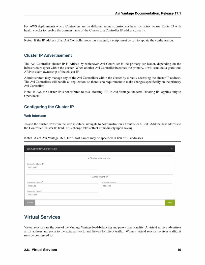
Web Interface
To add the cluster IP within the web interface, navigate to Administration > Controller > Edit. Add the new address tothe Controller Cluster IP field. This change takes effect immediately upon saving.
Note: As of Avi Vantage 16.3, DNS host names may be specified in lieu of IP addresses.
Virtual Services
Virtual services are the core of the Vantage Vantage load-balancing and proxy functionality. A virtual service advertisesan IP address and ports to the external world and listens for client traffic. When a virtual service receives traffic, itmay be configured to:
2.6. Virtual Services 19
Avi Vantage Documentation, Release 17.1
• Proxy the client’s network connection.
• Perform security, acceleration, load balancing, gather traffic statistics, and other tasks.
• Forward the client’s request data to the destination pool for load balancing.
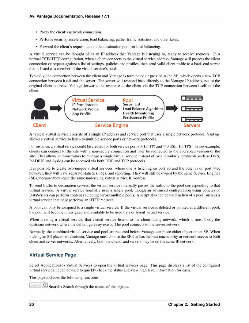
A virtual service can be thought of as an IP address that Vantage is listening to, ready to receive requests. In anormal TCP/HTTP configuration, when a client connects to the virtual service address, Vantage will process the clientconnection or request against a list of settings, policies and profiles, then send valid client traffic to a back-end serverthat is listed as a member of the virtual service’s pool.
Typically, the connection between the client and Vantage is terminated or proxied at the SE, which opens a new TCPconnection between itself and the server. The server will respond back directly to the Vantage IP address, not to theoriginal client address. Vantage forwards the response to the client via the TCP connection between itself and theclient.
A typical virtual service consists of a single IP address and service port that uses a single network protocol. Vantageallows a virtual service to listen to multiple service ports or network protocols.
For instance, a virtual service could be created for both service port 80 (HTTP) and 443 SSL (HTTPS). In this example,clients can connect to the site with a non-secure connection and later be redirected to the encrypted version of thesite. This allows administrators to manage a single virtual service instead of two. Similarly, protocols such as DNS,RADIUS and Syslog can be accessed via both UDP and TCP protocols.
It is possible to create two unique virtual services, where one is listening on port 80 and the other is on port 443;however, they will have separate statistics, logs, and reporting. They will still be owned by the same Service Engines(SEs) because they share the same underlying virtual service IP address.
To send traffic to destination servers, the virtual service internally passes the traffic to the pool corresponding to thatvirtual service. A virtual service normally uses a single pool, though an advanced configuration using policies orDataScripts can perform content switching across multiple pools. A script also can be used in lieu of a pool, such as avirtual service that only performs an HTTP redirect.
A pool can only be assigned to a single virtual service. If the virtual service is deleted or pointed at a different pool,the pool will become unassigned and available to be used by a different virtual service.
When creating a virtual service, that virtual service listens to the client-facing network, which is most likely theupstream network where the default gateway exists. The pool connects to the server network.
Normally, the combined virtual service and pool are required before Vantage can place either object on an SE. Whenmaking an SE placement decision, Vantage must choose the SE that has the best reachability or network access to bothclient and server networks. Alternatively, both the clients and servers may be on the same IP network.
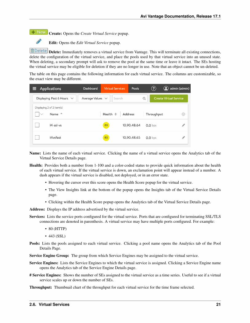
Virtual Service Page
Select Applications > Virtual Services to open the virtual services page. This page displays a list of the configuredvirtual services. It can be used to quickly check the status and view high level information for each.
This page includes the following functions:
Search: Search through the names of the objects.
20 Chapter 2. Getting Started
Avi Vantage Documentation, Release 17.1
Create: Opens the Create Virtual Service popup.
Edit: Opens the Edit Virtual Service popup.
Delete: Immediately removes a virtual service from Vantage. This will terminate all existing connections,delete the configuration of the virtual service, and place the pools used by that virtual service into an unused state.When deleting, a secondary prompt will ask to remove the pool at the same time or leave it intact. The SEs hostingthe virtual service may be eligible for deletion if they are no longer in use. Note that an object cannot be un-deleted.
The table on this page contains the following information for each virtual service. The columns are customizable, sothe exact view may be different.
Name: Lists the name of each virtual service. Clicking the name of a virtual service opens the Analytics tab of theVirtual Service Details page.
Health: Provides both a number from 1-100 and a color-coded status to provide quick information about the healthof each virtual service. If the virtual service is down, an exclamation point will appear instead of a number. Adash appears if the virtual service is disabled, not deployed, or in an error state.
• Hovering the cursor over this score opens the Health Score popup for the virtual service.
• The View Insights link at the bottom of the popup opens the Insights tab of the Virtual Service Detailspage.
• Clicking within the Health Score popup opens the Analytics tab of the Virtual Service Details page.
Address: Displays the IP address advertised by the virtual service.
Services: Lists the service ports configured for the virtual service. Ports that are configured for terminating SSL/TLSconnections are denoted in parenthesis. A virtual service may have multiple ports configured. For example:
• 80 (HTTP)
• 443 (SSL)
Pools: Lists the pools assigned to each virtual service. Clicking a pool name opens the Analytics tab of the PoolDetails Page.
Service Engine Group: The group from which Service Engines may be assigned to the virtual service.
Service Engines: Lists the Service Engines to which the virtual service is assigned. Clicking a Service Engine nameopens the Analytics tab of the Service Engine Details page.
# Service Engines: Shows the number of SEs assigned to the virtual service as a time series. Useful to see if a virtualservice scales up or down the number of SEs.
Throughput: Thumbnail chart of the throughput for each virtual service for the time frame selected.
2.6. Virtual Services 21
Avi Vantage Documentation, Release 17.1
• Hovering the cursor over this graph shows the throughput for the highlighted time.
• Clicking a graph opens the Analytics tab of the Virtual Service Details page for the virtual service.
Open Conns: Avg number of open connections.
Client RTT: The average TCP latency between clients of the virtual service and its SEs.
Server RTT: The average TCP latency between back-end servers of the virtual service and its SEs.
Conns: Rate of total connections per second.
Error Conns: Rate of errored connections per second.
Rx pkts: Average rate of packets received per second.
Tx pkts: Average rate of packets transmitted per second.
Policy Drops: Rate of total connections dropped due to VS policy per second. It includes drops due to rate limits,security policy drops, connection limits, etc.
DDoS Attacks: Number DDOS attacks occurring per second.
Alerts: Number of alerts related to the virtual service, pool, or Service Engines.
Virtual Services Details Pages
The Virtual Service Details pages shows extensive information about a virtual service. Access these pages by clickingthe name of a virtual service within the Applications > Dashboard or from the Applications > Virtual Service page.
The details pages are a loose collection of a number of sub-pages under the umbrella of the virtual service.
Virtual Service Alerts
Virtual Service Analytics
Virtual Service Clients
Virtual Service Events
Virtual Service Health
Virtual Service Logs
Virtual Service Security
Virtual Service Quick Info Popup
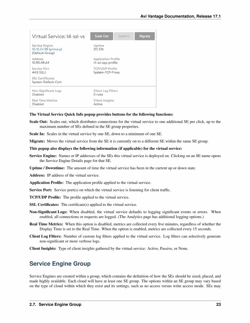
All of the virtual service details pages include the Virtual Service Quick Info popup, which may be accessed byhovering over or clicking the name of the virtual service in the top left corner of the page.
22 Chapter 2. Getting Started
Avi Vantage Documentation, Release 17.1
The Virtual Service Quick Info popup provides buttons for the following functions:
Scale Out: Scales out, which distributes connections for the virtual service to one additional SE per click, up to themaximum number of SEs defined in the SE group properties.
Scale In: Scales in the virtual service by one SE, down to a minimum of one SE.
Migrate: Moves the virtual service from the SE it is currently on to a different SE within the same SE group.
This popup also displays the following information (if applicable) for the virtual service:
Service Engine: Names or IP addresses of the SEs this virtual service is deployed on. Clicking on an SE name opensthe Service Engine Details page for that SE.
Uptime / Downtime: The amount of time the virtual service has been in the current up or down state.
Address: IP address of the virtual service.
Application Profile: The application profile applied to the virtual service.
Service Port: Service port(s) on which the virtual service is listening for client traffic.
TCP/UDP Profile: The profile applied to the virtual service.
SSL Certificates: The certificate(s) applied to the virtual service.
Non-Significant Logs: When disabled, the virtual service defaults to logging significant events or errors. Whenenabled, all connections or requests are logged. (The Analytics page has additional logging options.)
Real Time Metrics: When this option is disabled, metrics are collected every five minutes, regardless of whether theDisplay Time is set to the Real Time. When the option is enabled, metrics are collected every 15 seconds.
Client Log Filters: Number of custom log filters applied to the virtual service. Log filters can selectively generatenon-significant or more verbose logs.
Client Insights: Type of client insights gathered by the virtual service: Active, Passive, or None.
Service Engine Group
Service Engines are created within a group, which contains the definition of how the SEs should be sized, placed, andmade highly available. Each cloud will have at least one SE group. The options within an SE group may vary basedon the type of cloud within which they exist and its settings, such as no access versus write access mode. SEs may
2.7. Service Engine Group 23
Avi Vantage Documentation, Release 17.1
only exist within one group. Each group acts as an isolation domain. SE resources within an SE group may be movedaround to accommodate virtual services, but SE resources are never shared between SE groups.
Changes made to an SE group may be applied immediately, only applied to SEs created after the changes are made, orrequire existing SEs to first be disabled before the changes can take effect.
Multiple SE groups may exist within a cloud. A newly created virtual service will be placed on the default SE group,though this can be changed via the VS > Advanced page while creating a VS via the advanced wizard. To move anexisting virtual service from one SE group to another, the VS must first be disabled, moved, and then re-enabled. SEgroups provide data plane isolation, therefore moving a VS from one SE group to another is disruptive to existingconnections through the virtual service.
legacy-ha-gui1
BASIC SETTINGS TAB
To access the Service Engine group page, navigate to Infrastructure > Clouds > -cloudname- > Service Engine Group.Start your definition of an SE group by giving it a name.
REAL-TIME METRICS
Avi SE group metrics update frequency
At the top right of the Basic Settings tab you can turn on real-time metrics, which will cause SEs in the group to uploadSE-related metrics to the Controller once every 5 seconds, as opposed to once per five minutes or longer. [More infoon metrics-upload intervals.] After clicking the box, select the duration in minutes for real-time updating to last. Avalue of 0 is interpreted to mean “forever.”
HIGH AVAILABILITY & PLACEMENT SETTINGS
Avi Vantage service engine group high availability and placement settings
The high availability mode of the SE group controls the behavior of the SE group in the event of an SE failure. Italso controls how load is scaled across SEs. Selecting a particular HA mode will change the settings and options thatare exposed in the UI. These modes span a spectrum, from use of the fewest virtual machine resources on one end toproviding the best high availability on the other.
Legacy Active Standby HA Mode: This mode is primarily intended to mimic a legacy appliance load balancer for easymigration to Avi Vantage. Only two Service Engines may be created. For every virtual service active on one, there is astandby on the other, configured and ready to take over in case of a failure of the active SE. There is no Service Enginescale out in this HA mode. Elastic N + M HA Mode: This default mode permits up to N active SEs to deliver virtualservices, with the capacity equivalent of M SEs within the group ready to absorb SE(s) failure(s). Elastic Active/ActiveHA Mode: This HA mode distributes virtual services across a minimum of two SEs. For additional considerations forSE high availability, including VS placement, see Overview of Vantage High Availability. To compare the above HAmodes to those defined prior to Vantage 16.2, see Comparing Past and Present SE Group HA Modes.
VS Placement across SEs: When placement is compact (previously referred to as “Compactor”), Vantage prefers tospin up and fill up the minimum number of SEs; it tries to place virtual services on SEs which are already running.When placement is distributed, Vantage maximizes VS performance by avoiding placements on existing SEs. Instead,it places virtual services on newly spun-up SEs, up to Max Number of Service Engines. By default, placement iscompact for elastic HA N+M mode and legacy HA active/standby mode. By default, it is distributed for elastic HAactive/active mode.
Virtual Services per Service Engine: This parameter establishes the maximum number of virtual services the Controllercluster can place on any one of the SEs in the group.
24 Chapter 2. Getting Started
Avi Vantage Documentation, Release 17.1
Per Application SE mode: Select this option to deploy dedicated load balancers per application, i.e., per virtual service.In this mode, each SE is limited to a maximum of 2 virtual services. vCPUs in per-app SEs count towards licensing at25% rate.
SERVICE ENGINE CAPACITY AND LIMIT SETTINGS
Avi Vantage service engine group capacity and limit settings
Max Number of Service Engines: Defines the maximum SEs that may be created within an SE group. This number,combined with the virtual services per SE setting, dictate the maximum number of virtual services that can be createdwithin an SE group. If this limit is reached, it is possible new virtual services may not be able to be deployed andwill show a gray, un-deployed status. This setting can be useful to prevent Vantage from consuming too many virtualmachines. Memory per Service Engine: [Default = 2 GB, min = 1 GB] Enter the amount of RAM, in multiples of 1024MB, to allocate to all new SEs. Changes to this field will only affect newly-created SEs. Allocating more memory toan SE will allow larger HTTP cache sizes, more concurrent TCP connections, better protection against certain DDoSattacks, and increased storage of un-indexed logs. This option is only applicable in write access mode deployments.Memory Reserve: Reserving memory ensures an SE will not have contention issues with over-provisioned host hard-ware. Reserving memory makes that memory unavailable for use by another virtual machine, even when the virtualmachine that reserved those resources is powered down. Avi strongly recommends reserving memory, as memorycontention may randomly overwrite part of the SE memory, destabilizing the system. This option is applicable onlyfor deployments in write access mode. For deployments in read access mode deployments or no access mode, memoryreservation for the SE VM must be configured on the virtualization orchestrator. vCPU per Service Engine: [Default= 2] Enter the number of virtual CPU cores to allocate to new SEs. Changes to this setting do not affect existing SEs.This option is only applicable in write access mode. Adding CPU capacity will help with computationally expensivetasks, such as SSL processing or HTTP compression. CPU Reserve: Reserving CPU capacity with a virtualizationorchestrator ensures a SE will not have issues with over-provisioned host hardware. Reserving CPU cores makes thosecores unavailable for use by another virtual machine, even when the virtual machine that reserved those resources ispowered down. This option is only applicable in write access mode deployments. Disk per Service Engine: [min = 10GB] Specify an integral number of GB of disk to allocate to all new SEs.This option is only applicable in write accessmode deployments. The value appearing in the window is either: 10 GB (the absolute minimum allowed), or a valueauto-calculated by the UI as follows: 5 GB + 2 x memory-per-SE, or a number explicitly keyed in by the user (valuesless than 5 GB + 2 x memory-per-SE will be rejected) Connection Memory Percentage: The percentage of memoryreserved to maintain connection state. It comes at the expense of memory used for HTTP in-memory cache. Slidingthe bar causes the percentage to range between its limits, 10% minimum and 90% maximum.
ADVANCED TAB
The advanced tab in the Service Engine group popup supports configuration of optional functionality for SE groups.This tab only exists for clouds configured with write access mode. The appearance of some fields is contingent uponselections made.
Avi Vantage Service Engine Editor Advanced Tab
Service Engine Name Prefix: Enter the prefix to use when naming the SEs within the SE group. This name will beseen both within Vantage, and as the name of the virtual machine within the virtualization orchestrator.
Service Engine Folder: SE virtual machines for this SE group will be grouped under this folder name within thevirtualization orchestrator.
Delete Unused Service Engines After: Enter the number of minutes to wait before the Controller deletes an unusedSE. Traffic patterns can change quickly, and a virtual service may therefore need to scale across additional SEswith little notice. Setting this field to a high value ensures that Vantage keeps unused SEs around in case of asudden spike in traffic. A shorter value means the Controller may need to recreate a new SE to handle a burst oftraffic, which may take a couple of minutes.
2.7. Service Engine Group 25
Avi Vantage Documentation, Release 17.1
HOST & DATA STORE SCOPE
Host Scope Service Engine: SEs may be deployed on any host that most closely matches the resources and reacha-bility criteria for placement. This setting directs the placement of SEs.
Any: The default setting allows SEs to be deployed to any host that best fits the deployment criteria.
Cluster: Excludes SEs from deploying within specified clusters of hosts. Checking the Include checkbox reverses thelogic, ensuring SEs only deploy within specified clusters.
Host: Excludes SEs from deploying on specified hosts. The Include checkbox reverses the logic, ensuring SEs onlybe deploy within specified hosts.
Data Store Scope for Service Engine Virtual Machine: Set the storage location for SEs. Storage is used to storethe OVA (vmdk) file for VMware deployments.shared data store scope
Any: Vantage will determine the best option for data storage.
Local: The SE will only use storage on the physical host.
Shared: Vantage will prefer using the shared storage location. When this option is clicked, specific data stores maybe identified for exclusion or inclusion.
ADVANCED HA & PLACEMENT
Buffer Service Engines: This is excess capacity provisioned for HA failover. In elastic HA N+M mode, this iscapacity is expressed as M, an integer number of buffer service engines. It actually translates into a count ofpotential VS plabuffer service engines represent spare capacity dedicated for SE HAcements. To calculate thatcount, Vantage multiplies M by the maximum number of virtual services per SE. For example, if one requests 2buffer SEs (M=2) and the max_VS_per_SE is 5, the count is 10. If max SEs/group hasn’t been reached, Vantagewill spin up additional SEs to maintain the ability to perform 10 placements. As illustrated at right, six virtualservices have already been placed, and the current count of spare capacity is 14, more than enough to perform10 placements. When SE2 fills up, spare capacity will be just right. An 11th placement on SE3 would reducethe count to 9 and require SE5 to be spun up.
Scale Per Virtual Service: A pair of integers determine the minimum and maximum number of active SEs any virtualservice within this group can scale out to. With native SE scaling, the greatest value one can enter as a maximumis 4; with BGP-based SE scaling, it is 32.
Service Engine Failure Detection: This option refers to the time Vantage takes to conclude SE takeover should takeplace. Standard is approximately 9 seconds and aggressive 1.5 seconds.
Auto-Rebalance: If this option is selected, virtual services are automatically migrated (scaled in or out) when CPUloads on SEs fall below the minimum threshold or exceed the maximum threshold. If this option is off, theresult is limited to an alert. The frequency with which Vantage evaluates the need to rebalance can be set tosome number of seconds.
CPU socket Affinity: Selecting this option causes Vantage to allocate all cores for SE VMs on the same socket of amulti-socket CPU. The option is applicable only in vCenter environments. Appropriate physical resources needto be present in the ESX Host. If not, then SE creation will fail and manual intervention will be required.
Dedicated dispatcher CPU: Selecting this option dedicates the core that handles packet receive/transmit from/to thedata network to just the dispatching function. This option makes most sense in a group whose SEs have three ormore vCPUs.
Override Management Network: If the SEs require a different network for management than the Controller, it mustbe specified here. The SEs will use their management route to establish communications with the Controllers.See Deploy SEs in Different Datacenter from Controllers.
26 Chapter 2. Getting Started
Avi Vantage Documentation, Release 17.1
Note: This option is only available if the SE group’s overridden management network is DHCP-defined. An admin-istrator’s attempt to override a statically-defined management network (Infrastructure –> Cloud –> Network) will notwork due to not allowing a default gateway in the statically-defined subnet.
SECURITY
HSM Group: Hardware security modules may be configured within the Templates > Security > HSM Groups. AnHSM is an external security appliance that is used for secure storage of SSL certificates and keys. The HSMGroup dictates how Service Engines can reach and authenticate with the HSM. See Physical Security for SSLKeys.
Pools
Contents
• Pools
– What is a Pool?
– Pools Page
– Pool Details Page
* Pool Analytics Page
* Pool End-to-End Timing
* Pool Metrics
* Pool Chart Pane
What is a Pool?
Pools maintain the list of servers assigned to them and perform health monitoring, load balancing, persistence, andfunctions that involve Avi-Vantage-to-server interaction. A typical virtual service will point to one pool; however,more advanced configurations may have a virtual service content switching across multiple pools via HTTP requestpolicies or DataScripts. A pool may only be used or referenced by only one virtual service at a time.
architecture_1
Creating a virtual service using the basic method automatically creates a new pool for that virtual service, using thename of the virtual service with a -pool appended. When creating a virtual service via the advanced mode, an existing,unused pool may be specified, or a new pool may be created.
Pools Page
Select Applications > Pools to open the pools page. This page displays a high level overview of configured pools. Thispage includes the following functions:
icon_search Search: Filter the list of pools by entering full or partial name of a pool.
icon_new Create: Opens the create pool popup.
2.8. Pools 27
Avi Vantage Documentation, Release 17.1
icon_edit_white Edit: Opens the edit pool popup.
icon_delete Delete: Select one or more pools in the table and click the delete button at the top left of the table to deletethe pools. Only unused pools (with a gray health score) may be deleted. Pools that are in use (e.g. pools referencedby a virtual service) must first be disassociated from the virtual service by deleting or editing the VS.
The table on this page displays the following information for each pool. The columns shown may be modified via thesprocket icon in the top right of the table:
Name: Lists the name of each pool. Clicking the name opens the Analytics tab of the Pool Details page. Health:Provides both a number from 1-100 and a color-coded status to provide quick information about the health of eachpool. This will be gray if the pool is unused, such as not associated with a virtual service or associated with a VS thatcan not or has not been placed on a Service Engine. Hovering the cursor over the health score opens the pool’s HealthScore popup. Clicking the View Insights link at the bottom of the pool’s Health Score popup opens the health Insightstab of the Pool Detail page. Clicking elsewhere within the pool’s Health Score popup opens the Analytics tab of thePool Details page. Servers: Displays the number of servers in the pool that are up out of the total number of serversassigned to the pool. For example, 2/3 indicates that two of the three servers in the pool are successfully passinghealth checks and are considered up. Virtual Service: The VS the pool is assigned to. Clicking a name in this columnopens the VS Analytics tab of the Virtual Service Details page. If no virtual service is listed, this pool is consideredunused. Throughput: Thumbnail chart of the throughput in Mbps for each pool for the time frame selected. Hoveringthe cursor over this graph shows the throughput at the selected time. Clicking a graph opens the Analytics tab of thepool’s Details page.
Pool Details Page
Clicking into a pool brings up the Details pages, which provide deeper views into the current pool.
This page contains the following sub-pages:
Contents
• Pools
– What is a Pool?
– Pools Page
– Pool Details Page
* Pool Analytics Page
* Pool End-to-End Timing
* Pool Metrics
* Pool Chart Pane
Pool Analytics Page
The pool’s Analytics tab presents information about various pool performance metrics. Data shown is filtered by thetime period selected.
details_analytics_about_7
See the following for detailed information about this tab:
1. End-to-End Timing
2. Metric Tiles
28 Chapter 2. Getting Started
Avi Vantage Documentation, Release 17.1
3. Chart Pane
4. Overlays Pane
• Anomalies
• Alerts
• Config Events
• System Events
Pool End-to-End Timing
The End to End Timing pane at the top of the Analytics tab of the Pool Details Page provides a high-level overview ofthe quality of the end-user experience and where any slowdowns may be occurring. The chart breaks down the timerequired to complete a single transaction, such an HTTP request.
It may be helpful to compare the end-to-end time against other metrics, such as throughput, to see how increases intraffic impact the ability of the application to respond. For instance, if new connections double but the end-to-end timequadruples, you may need to consider adding additional servers.
template_profiles_analytics_create-edit4
From left to right, this pane displays the following timing information:
Server RTT: This is Service Engine to server round trip latency. An abnormally high Server RTT may indicate eitherthat the network is saturated or more likely that a server’s TCP stack is overwhelmed and cannot quickly establish newconnections. App Response: The time the servers take to respond. This includes the time the server took to generatecontent, potentially fetch back-end database queries or remote calls to other applications, and begin transferring theresponse back to Avi Vantage. This time is calculated by subtracting the Server RTT from the time of the first byte ofa response from the server. If the application consists of multiple tiers (such as web, applications, and database), thenthe App Response represents the combined time before the server in the pool began responding. This metric is onlyavailable for a layer 7 virtual service. Data Transfer: Data Transfer represents the average time required for the serverto transmit the requested file. This is calculated by measuring from the time the Service Engine received the first byteof the server response until the client has received the last byte, which is measured as the when the last byte was sentfrom the Service Engine plus one half of a client round trip time. This number may vary greatly depending on thesize of objects requested and the latency of the server network. The larger the file, the more TCP round trip times arerequired due to ACKs, which are directly impacted by the Client RTT and Server RTT. This metric is only used for aLayer 7 virtual service. Total Time: Total time from when a client sent a request until they receive the response. Thisis the most important end-to-end timing number to watch, because it is the sum of the other four metrics. As long asit is consistently low, the application is probably successfully serving traffic.
Pool Metrics
The sidebar metrics tiles contain the following metrics for the pool. Clicking any metric tile will change the main chartpane to show the chosen metric.
infra-pool-metric1End to End Timing: Shows the total time from the pool’s End to End Timing graph. To see the com-plete end-to-end timing, including the client latency, see the Analytics tab of the Virtual Service Details page, whichincludes the client to Service Engine metric. infra-pool-metric2Open Connections: The number of open (existing)connections during the selected time period. infra-pool-metric3New Connections: The number of client connectionsthat were completed or closed over the selected time period. See this article for an explanation of new versus closedconnections per second. infra-pool-metric4Throughput: Total bandwidth passing between the virtual service and theservers assigned to the pool. This throughput number may be different than the virtual service throughput, which mea-sures throughput between the client and the virtual service. Many features may affect these numbers between the clientand server side of Avi Vantage, such as caching, compression, SSL, and TCP multiplexing. Hovering your mouse cur-sor over this graph displays the throughput in Mbps for the selected time period. infra-pool-metric5Requests: The
2.8. Pools 29
Avi Vantage Documentation, Release 17.1
number of HTTP requests sent to the servers assigned to the pool. This metric also shows errors sent to servers orreturned by servers. Any client requests that received an error generated by Avi Vantage as a response (such as a500 when no servers are available) are not be forwarded to the pool and will not be tracked in this view. infra-pool-metric6Servers: Displays the number of servers in the pool and their health. The X-axis represents the number ofHTTP requests or connections to the server, while the Y-axis represents the health score of the server. The chart allowsyou to view servers in relation to their peers within the pool, thus helping to spot outliers. Within the chart pane, clickand drag the mouse over server dots to select and display a table of the highlighted servers below the Chart pane. Thetable provides more details about these servers, such as hostname, IP address, health, new connections or requests,health score, and the server’s static load balanced ratio. Clicking on the name of a server will jump to the pool’s ServerInsight page, which shows additional health and resource status.
Pool Chart Pane
The main chart pane in the middle of the Analytics tab displays a detailed historical chart of the selected metric tilefor the current pool.
Hovering the mouse over any point in the chart will display the results for that selected time in a popup window.Clicking within the chart will freeze the popup at that point in time. This may be useful when the chart is scrolling asthe display updates over time. Clicking again will unfreeze the highlighted point in time. inf_chart_pane
Many charts contain radio buttons in the top right that allow customization of data that should be included or excludedfrom the chart. For example, if the End to End Timing chart is heavily skewed by one very large metric, then deselect-ing that metric by clearing the appropriate radio button will re-factor the chart based on the remaining metrics shown.This may change the value of the vertical Y-axis.
Some charts also contain overlay items, which will appear as color-coded icons along the bottom of the chart.
Pool Overlays Pane The overlays pane is used to highlight important events within the timeline of the chart pane. Thisfeature helps correlate anomalies, alerts, configuration changes, or system events with changes in traffic patterns.
overlays
Within the overlays pane:
Each overlay type displays the number of entries for the selected time period. Clicking an overlay button toggles thatoverlay’s icons in the chart pane. The button lists the number of instances (if any) of that event type within the selectedtime period. Selecting an overlay button displays the icon for the selected event type along the bottom of the chart pane.Multiple overlay icon types may overlap. Clicking the overlay type’s icon in the chart pane will bring up additionaldata below the overlay Items bar. The following overlay types are available: Anomalies: Display anomalous trafficevents, such as a spike in server response time, along with corresponding metrics collected during that time period.Alerts: Display alerts, which are filtered system-level events that have been deemed important enough to notify anadministrator. Config Events: Display configuration events, which track configuration changes made to Avi Vantageby either an administrator or an automated process. System Events: Display system events, which are raw data pointsor metrics of interest. System Events can be noisy, and are best used as the basis of alerts which filter and classifyraw events by severity. Pool Anomalies Overlay The anomalies overlay displays periods during which traffic behaviorwas considered abnormal based on recent historical moving averages. Changing the time interval will provide greatergranularity and potentially show more anomalies.
Clicking the Anomalies Overlay button overlays_anomalies displays yellow anomaly icons in the chart pane. Selectingone of these icons within the chart pane brings up additional information in a table at the bottom of the page. Duringtimes of anomalous traffic, Avi Vantage records any metrics that have deviated from the norm, which may providehints as to the root cause of the anomaly.
An anomaly is defined as a metric that has a deviation of 4 sigma or greater across the moving average of the chart.
Anomalies are not recorded or displayed while viewing with the Real Time display period.
details_overlays_anomalies
30 Chapter 2. Getting Started
Avi Vantage Documentation, Release 17.1
Timestamp: Date and time when the anomaly was detected. This may either span the full duration of the anomaly, ormerely be near the same time window. Type: The specific metric deviating from the norm during the anomaly period.To be included, the metric deviation must be greater than 4 sigma. Numerous types of metrics, such as CPU utilization,bandwidth, or disk I/O may trigger anomalous events. Entity: Name of the specific object that is reporting this metric.Entity Type: Type of entity that caused the anomaly. This may be one of the following: Virtual Machine (server); thesemetrics require Avi Vantage to be configured for either read or write access to the virtualization orchestrator such asvCenter or OpenStack. In the example shown above, CPU utilization of the two servers was learned by queryingvCenter. Virtual service Service Engine Time Series: Thumbnail historical graph for the selected metric, includingthe most current value for the metric which will be data on the far right. Moving the mouse over the chart pane willshow the value of the metric for the selected time. Use this to compare the normal, current, and anomaly time periods.Deviation: Change or deviation from the moving average, either higher or lower. The time window for the movingaverage depends on the time series selected for the Analytics tab. Pool Alerts Overlay The alerts overlay displaysthe results of any events that meet the filtering criteria defined in the alerts tab. Alerts notify administrators aboutimportant information or changes to a site that may require immediate attention.
Alerts may be transitory, meaning that they may expire after a defined period of time. For instance, Avi Vantage maygenerate an alert if a server is down and then allow that alert to expire after a specified time period once the servercomes back online. The original event remains available for later troubleshooting purposes.
Clicking the alerts icon details_overlays_alerts_6-d-c in the overlay items bar displays any red alerts icons in the chartpane. Selecting one of these chart alerts will bring up additional information below the overlay Items bar, which willshow the following information:
details_overlays_alerts
Timestamp: Date and time when the alert occurred. Resource Name: Name of the object that is reporting the alert.Level: Severity of the alert. You can use the priority level to determine whether additional notifications should occur,such as sending an email to administrators or sending a log to Syslog servers. The level may be one of the following:High: Red Medium: Yellow Low: Blue Summary: Brief description of the event. Actions: Dismiss the alert with thered X to remove it from both the list shown and the alert icon the chart pane. Dismissing an alert here is the sameas dismissing it via the bell icon at the top of the screen next to the health score, or dismissing it via the alerts tab.Edit the alert filter to make Avi Vantage more or less sensitive to generating new Alerts. Expand/Contract: Clickingthe plus (+) or minus sign (-) for an Alert opens and closes a sub-table showing more detail about the alert. Thiswill typically show the original events that triggered the alert. Pool Config Events Overlay The config events overlaydisplays configuration events, such as changing the Avi Vantage configuration by adding, deleting, or modifying apool, virtual service, or Service Engine, or an object related to the object being inspected. If traffic dropped off atprecisely 10:00am, and at that time an administrator made a change to the virtual services security settings, there’s agood chance the cause of the change in traffic was due to the (mis)configuration.
details_overlays_config_events
Clicking the Config Events icon details_overlays_config-events_6-d-d in the Overlay Items bar displays any blueconfig event icons in the chart pane. Selecting one of these chart alerts will bring up additional information below theOverlay Items bar, which will show the following information:
Timestamp: Date and time when the configuration change occurred. Event Type: This event type will always bescoped to configuration event types. Resource Name: Name of the object that has been modified. Event Code: Thereare three event codes: CONFIG_CREATE CONFIG_UPDATE CONFIG_DELETE Description: Brief descriptionof the event. Expand/Contract: Clicking the plus (+) or minus sign (-) for a configuration event either expands orcontracts a sub-table showing more detail about the event. When expanded, this shows a difference comparison ofthe previous configuration versus the new configuration, as follows: Additions to the configuration, such as adding ahealth monitor, will be highlighted in green in the new configuration. Removing a setting will be highlighted in redin the previous configuration. Changing an existing setting will be highlighted in yellow in both the previous and newconfigurations. Pool System Events Overlay This overlay displays system events relevant to the current object, suchas a server changing status from up to down or the health score of a virtual service changing from 50 to 100.
details_overlays_events
2.8. Pools 31
Avi Vantage Documentation, Release 17.1
Clicking the system events icon details_overlays_sys-events_6-d-e in the overlay items bar displays any purple systemevent icons in the Chart Pane. Select a system event icon in the chart pane to bring up more information below theoverlay items bar.
Timestamp: Date and time when the system even occurred. Event Type: This will always be system. Resource Name:Name of the object that triggered the event. Event Code: High-level definition of the event, such as VS_Health_Changeor VS_Up. Description: Brief description of the system event. Expand/Contract: Clicking the plus (+) or minus sign(-) for a system event expands or contracts that system event to show more information.
Pool Logs Page Client logs viewed from within a pool are identical to the logs shown within a virtual service, exceptthey are filtered to only show log data specific to the pool. For instance, information such as End to End Timing isonly shown from the Service Engine to the servers, rather than from the clients to the servers. Viewing logs within apool may be useful when a virtual service is performing content switching across multiple pools. It is still possiblewithin the virtual service logs page to add a filter for a specific pool, which would then provide complete End to EndTiming for connections or requests sent to the specified pool.
For the complete descriptions of logs, see the VS logs page help.
Pool Health Page The health tab presents a detailed breakdown of health score information for the pool.
details_insights_tab_8
The health score of a pool is comprised from the following scores:
Performance: Performance score (1-100) for the selected item. A score of 100 is ideal, meaning clients are notreceiving errors and connections or requests are quickly returned. Resource Penalty: Any penalty assessed becauseof resource availability issues is assigned a score, which is then subtracted from the performance score. A penaltyscore of 0 is ideal, meaning there are no obvious resource constraints on Avi Vantage or servers. Anomaly Penalty:Any penalty assessed because of anomalous events is assigned a score, which is then subtracted from the performancescore. An ideal score is 0, which means Avi Vantage has not seen recent anomalous traffic patterns that may implyfuture risk to the site. Health Score: The final health score for the selected item equals the performance score minusthe Resource and anomaly penalty scores The sidebar tiles show the scores of each of the three subcomponents of thehealth score, plus the total score. To determine why a pool may have a low health score, select one of the first threetiles that is showing a sub-par score.
This will bring up additional sub-metrics which feed into the top level metric / tile selected. Hover the mouse overa time period in the main chart to see the description of the score degradation. Some tiles may have additionalinformation shown in the main chart section that requires scrolling down to view.
Pool Servers Page Information for each server within a pool is available within the Server Details Page. This pageallows views into correlation between server resources, application traffic, and response times.
Server Page The Server Page may be accessed by clicking on the server’s name from either the Pool > Servers page orthe Pool > Analytics Servers tile. When viewing the Server Details page, the server shown is within the context of thepool it was selected within. Rephrased, if the server (IP:Port) is a member of two or more pools, the stats and healthmonitors shown are only for the server within the context of the viewed pool.
apps_pools_details_servers
Not all metrics within the Server Page are available in all environments. For instance, servers that are not virtualizedor hooked into a hypervisor are not able to have their physical resources displayed.
apps_servers_details_page
The statistics can be changed or skewed by switching between Average Values, Peak Values, and Current Values. Tosee the highest CPU usage over the past day, change the time to 24 hour and the Value to Peak. This will show thehighest stats recorded during the past day.
CPU Stats: The CPU Stats box shows the CPU usage for this server, the average during this time period across allservers in the pool, and the hypervisor host. Memory Stats: The memory Stats box shows the Memory usage for thisserver, the average during this time period across all servers in the pool, and the hypervisor host. Health Monitor:
32 Chapter 2. Getting Started
Avi Vantage Documentation, Release 17.1
This table shows the name of any health monitors configured for the pool. The Status column shows the most currentup or down health of the server. The Success column shows the percentage of health monitors that passed or failedduring the display time frame. Clicking the plus will expand the table to show more info for a down server. See Why aServer Can Be Marked Down. Main Panel: The large panel shows the highlighted metric, similar to the Virtual ServiceDetails and Pool Details pages. Overlay Items shows anomalies, alerts, configuration events, and system events thatare related to this server within the pool. Pool Tile Bar: The pool in the top right bar shows the health of the pool. Thiscan also be used to jump back up to the Pool Page. Under the pool name is a pull-down menu that allows quick accessto jumping to the other servers within the pool. Metrics Tile Bar: The metrics options will vary depending on thehypervisor Avi Vantage is plugged into. For non-virtualized servers, the metrics are limited to non-resource metrics,such as end-to-end timing, throughput, open connections, new connections, and requests. Other metrics that may beshown include CPU, memory, and virtual disk throughput.
Pool Events Page The events tab presents system-generated events over the time period selected for the pool. Systemevents are applicable to the context in which you are viewing them. For example, when viewing events for a pool,only events that are relevant to that pool are displayed.
details_events_tab_9
The top of this tab displays the following items:
Search: The search field allows you to filter the events using whole words contained within the individual events.Refresh: Clicking refresh updates the events displayed for the currently-selected time. Number: The total number ofevents being displayed. The date/time range of those events appear beneath the search field on the left. Clear Selected:If filters have been added to the Search field, clicking the Clear Selected (X) icon on the right side of the search barwill remove those filters. Each active search filter will also contain an X that you can click to remove the specificfilter. Histogram: The histogram shows the number of events over the period of time selected. The X-axis is time,while the Y-axis is the number of events during that bar’s period of time. Hovering the cursor over a histogram bardisplays the number of entries represented by that bar, or period of time. Click and drag inside the histogram to refinethe date/time period which further filters the events shown. When drilling in on the time in the histogram, a zoom toselected link appears above the histogram. This expands the drilled in time to expand to the width of the histogram,and also changes the displaying pull-down menu to custom. To return to the previously selected time period, use thedisplaying pull-down menu. The table at the bottom of the events tab displays the events that matched the current timewindow and any potential filters. The following information appears for each event:
Timestamp: Date and time the event occurred. Highlighting a section of the histogram allows further filtering of eventswithin a smaller time window. Event Type: This may be one of the following: System: System events are generatedby Avi Vantage to indicate a potential issue or create an informational record, such as VS_Down, Configuration: Con-figuration events track changes to the Avi Vantage configuration. These changes may be made by an administrator(through the CLI, API, or GUI), or by automated policies. Resource Name: Name of the object related to the event,such as the pool, virtual service, Service Engine, or Controller. Event Code: A short event definition, such as Con-fig_Action or Server_Down. Description: A complete event definition. For configuration events, the description willalso show the username that made the change. Expand/Contract: Clicking the plus (+) or minus sign (-) for an eventlog either expands or contracts that event log. Clicking the + and – icons in the table header expands and collapsesall entries in this tab. For configuration events, expanding the event displays a difference comparison between theprevious and new configurations.
New fields will appear highlighted in green in the new configuration Removed fields will appear highlighted in red.Changed fields will show highlighted in yellow
Pool Alerts Page The alerts tab displays user-specified events for the selected time period. You can configure alertactions and proactive notifications via Syslog or email in the Notifications tab of the Administration page. Alerts actas filters that provide notification for prioritized events or combinations of events through various mechanisms. AviVantage includes a number of default alerts based on events deemed to be universally important.
details_alerts_tab_10
The top of this tab shows the following items:
Search: The search field allows you to filter the alerts using whole words contained within the individual alerts.
2.8. Pools 33
Avi Vantage Documentation, Release 17.1
Refresh: Clicking refresh updates the alerts displayed for the currently-selected time. Number: The total number ofalerts being displayed. The date/time range of those alerts appear beneath the search field on the left. Dismiss: Selectone or more alerts from the table below then click dismiss to remove the alert from the list. Alerts are transitory, whichmeans they will eventually and automatically expire. Their intent is to notify an administrator of an issue, rather thanbeing the definitive record for issues. Alerts are based on events, and the parent event will still be in the Events record.
The table at the bottom of the Alerts tab displays the following alert details:
Timestamp: Date and time when the alert was triggered. Changing the time interval using the display pull-down menumay potentially show more alerts. Resource Name: Name of the object that is the subject of the alert, such as aServer or virtual service. Level: Severity level of the alert, which can be high, medium, or low. Specific notificationscan be set up for the different levels of alerts via the Administration page’s Alerts Overlay. Summary: Summarizeddescription of the alert. Action: Click the appropriate button to act on the alert: Dismiss: Clicking the red X dismissesthe alert and removes it from the list of displayed alerts. Edit: Clicking the blue pencil icon opens the Edit Alert Configpopup for the alert configuration that triggered this alert. This can include a verbose and customized description of thealert or allow an administrator to alter settings such as the severity of the alert. Expand/Contract: Clicking the plus (+)or minus sign (-) for an event log either expands or contracts that event log to display more information. Clicking the+ and – icon in the table header expands and collapses all entries in this tab Create Pool The Create Pool popup andthe Edit Pool popup share the same interface that consists of the following tabs:
Settings Servers Advanced Review Create Pool: 1 Settings
The Create/Edit Pool > Settings tab contains the basic settings for the pool. The exact options shown may varydepending on the types of clouds configured in Avi Vantage. For instance, servers in VMware may show an option to“Select Servers by Network” or Cisco ACI integration may show lists of “End Point Groups”.
To add or edit Pool settings:
Name: Provide a unique name for the pool. Default Server Port: Select one of the following: Default Server Port:New connections to servers will use this destination service port. The default port is 80, unless it is either inheritedfrom the virtual service (if the pool was created during the same workflow), or the port was manually assigned. Thedefault server port setting may be changed on a per-server basis by editing the Service Port field for individual serversin the Servers tab. SSL: Enables SSL encryption between the Avi Vantage Service Engine and the back-end servers.This is independent from the SSL option in the virtual service, which enables SSL encryption from the client to theAvi Vantage Service Engine. SSL Profile: Determines which SSL versions and ciphers Avi Vantage will support whennegotiating SSL with the server. Server SSL Certificate Validation PKI Profile: This option validates the certificatepresented by the server. When not enabled, the Service Engine automatically accepts the certificate presented by theserver when sending health checks. See the PKI Profile section for additional help on certificate validation. ServiceEngine Client Certificate: When establishing an SSL connection with a server, either for normal client-to-servercommunications or when executing a health monitor, the Service Engine will use this certificate to present to theserver.
Load Balance: Select a load-balancing algorithm using the Algorithm pull-down menu. This choice determines themethod and prioritization for distributing connections or HTTP requests across available servers. The available op-tions are: Consistent Hash: New connections are distributed across the servers using a hash that is based on a keyspecified in the field that appears below the LB Algorithm field. This algorithm inherently combines load balancingand persistence, which minimizes the need to add a persistence method. This algorithm is best for load balancinglarge numbers of cache servers with dynamic content. It is ‘consistent’ because adding or removing a server doesnot cause a complete recalculation of the hash table. For the example of cache servers, it will not force all caches tohave to re-cache all content. If a pool has nine servers, adding a tenth server will cause the pre-existing servers tosend approximately 1/9 of their hits to the newly-added server based on the outcome of the hash. Hence persistencemay still be valuable. The rest of the server’s connections will not be disrupted. The available hash keys are: CustomHeader: Specify the HTTP header to use in the Custom Header field, such as Referer. This field is case sensitive. Ifthe field is blank or if the header does not exist, the connection or request is considered a miss, and will hash to aserver. Source IP Address of the client. Source IP Address and Port of the client. HTTP URI, which includes the Hostheader and the Path. For instance, www.avinetworks.com/index.htm Fastest Response: New connections are sent tothe server that is currently providing the fastest response to new connections or requests. This is measured as time
34 Chapter 2. Getting Started
Avi Vantage Documentation, Release 17.1
to first byte. In the End to End Timing chart, this is reflected as Server RTT plus App Response time. This optionis best when the pool’s servers contain varying capabilities or they are processing short-lived connections. A serverthat is having issues, such as a lost connection to the data store containing images, will generally respond very quicklywith HTTP 404 errors. It is best practice when using the Fastest Response algorithm to also enable the Passive HealthMonitor, which recognizes and adjusts for scenarios like this by taking into account the quality of server response,not just speed of response. Note: A server that is having issues, such as a lost connection to the data store containingimages, will generally respond very quickly with HTTP 404 errors. You should therefore use the Fastest Responsealgorithm in conjunction with the Passive Health Monitor, which recognizes and adjusts for scenarios like this. FewestServers: Instead of attempting to distribute all connections or requests across all servers, Avi Vantage will determinethe fewest number of servers required to satisfy the current client load. Excess servers will no longer receive traffic andmay be either de-provisioned or temporarily powered down. This algorithm monitors server capacity by adjusting theload and monitoring the server’s corresponding changes in response latency. Connections are sent to the first serverin the pool until it is deemed at capacity, with the next new connections sent to the next available server down theline. This algorithm is best for hosted environments where virtual machines incur a cost. Least Connections: Newconnections are sent to the server that currently has the least number of outstanding concurrent connections. This isthe default algorithm when creating a new pool and is best for general-purpose servers and protocols. New serverswith zero connections are introduced gracefully over a short period of time via the Connection Ramp setting in theStep 3: Advanced tab, which slowly brings the new server up to the connection levels of other servers within the pool.Note: A server that is having issues, such as rejecting all new connections, will have a concurrent connection countof zero and be the most eligible to receive all new connections that will fail. Use the Least Connections algorithm inconjunction with the Passive Health Monitor which recognizes and adjusts for scenarios like this. Least Load: Newconnections are sent to the server with the lightest load, regardless of the number of connections that server has. Forexample, if an HTTP request that will require a 200k response is sent to a server and a second request that will generatea 1k response is sent to a server, this algorithm will estimate that —based on previous requests— the server sendingthe 1k response is more available than the one still streaming the 200k of data. The idea is to ensure that a small andfast request does not get queued behind a very long request. This algorithm is HTTP specific. For non-HTTP traffic,the algorithm will default to the Least Connections algorithm. Round Robin: New connections are sent to the nexteligible server in the pool in sequential order. This static algorithm is best for basic load testing, but is not ideal forproduction traffic because it does not take the varying speeds or periodic hiccups of individual servers into account.There are several other factors beyond the Load Balancing algorithm that can affect connection distribution, such asConnection Multiplexing, server Ratio, Connection Ramp, and server Persistence.
Persistence: By default, Avi Vantage will load balance clients to a new servers each time the client opens a newconnection to a virtual sService, and there is no guarantee that the client will reconnect to the same server that theywere previously connected to. A Persistence Profile ensures that subsequent connections from the same client willconnect to the same server. Persistence can be thought of as the opposite of load balancing: a client’s first connectionto Avi Vantage is load balanced; thereafter, that client and any connections made by it will be persisted to the sameserver for the desired duration of time. Persistent connections are critical for most servers that maintain client sessioninformation locally. For example, many HTTP applications will keep a user’s information in memory for 20 minutes,which allows the user to continue their session by reconnecting to the same server.As a best practice, HTTP virtualservices requiring persistence should use HTTP Cookies, while general TCP or UDP applications requiring persistencewill use Source IP. For more information on persistence types, see Persistence Profiles. Health Monitor: Avi Vantageuses health monitors to generate synthetic connections or requests to servers to ensure the integrity of the server’shealth. You may add one or more health monitors to the pool by clicking the green add button and either selectinga health monitor or clicking the create health monitor button. You may also: Disassociate a health monitor from thepool by clicking the trash can icon to the right of the monitor name. Edit an associated health monitor by clicking theblue edit pencil icon to the right of the associated monitor’s name. Passive Health Monitor: A passive health monitorwatches all client interactions with the site. If servers are sending errors (such 500 Busy or TCP connection errors),then the passive health monitor will reduce the amount of connections or requests sent to that server. The reductionpercentage depends on the number of servers available within the pool. As the server responds satisfactorily to thethrottled requests directed to it, the passive health monitor will restore the server to full traffic volume. You may usethis monitor in conjunction with any other health monitors. Errors are defined in the Analytics profile assigned to thevirtual service. Best practice is to ensure Passive Health Monitor is enabled in addition to any synthetic check thatmay also be configured. Create Pool: 2 Servers
2.8. Pools 35
Avi Vantage Documentation, Release 17.1
The Servers tab contains the server list for the pool.
Add Servers
IP Address, Range, or DNS Name: Add one or more servers to the pool using one or more of the listed methods. Theexample below shows servers created using multiple methods. Add by IP Address: Enter the IP address for the serverthat you want to include in the Address field, then click the green Add Server button. You may also enter a range ofIP addresses via a dash, such as 10.0.0.1-10.0.0.20. Add by DNS Resolvable Name: Enter the name of the server inthe Address field. If the server successfully resolves, the IP address will appear and the Add Server button will changeto green. Click Add Server to include in the pool server list. See Add Servers by DNS Select Servers by Network:This option is only available if Avi Vantage has read or write access to the cloud orchestrator. Click the Select Serversby Network button to open a list of reachable networks. Select a network to open a list of servers (virtual machines)available on that network. Filter the search for servers, such as searching for “apache” then select all matching servers.Click the green Add Servers button to include the new servers in the pool.Adding servers using the Select Servers byNetwork method allows Avi Vantage to provide significantly richer information regarding the server. Avi Vantage isable to query the virtualization orchestrator for the virtual machine’s CPU, memory, and disk utilization. This is usefulfor better load balancing and visibility, and is the best-practice method. Adding servers by IP address or name willnot provide this information. After a server has been added via the method, the server’s Network column in the serverlist table will be populated with the network or port group. See Select Servers by Network for more help. IP Group:Rather than add servers to an individual pool, server IP addresses may be added to an IP Group. This may be useful ifthe same group is used elsewhere for IP whitelists, DataScripts, or similar automation purposes. Many common poolfeatures are unavailable when using this method, such as manually disabling a server, setting a specific service port,or setting a ratio. The IP Group method for adding servers may not be used with other methods. Servers
Changing Server Status: Adding servers to the pool populates the primary table of the Servers tab, where you may nowremove, enable, disable, or gracefully disable them. Changes to server status take effect immediately when you saveyour changes. Remove: Select one or more servers to remove from the pool. This will immediately reset any existingclient connections for these servers and purge the server from the pool’s list. Enable: Select one or more disabledservers, and then reactive them by clicking the Enable button. Enabling a server makes that server immediatelyavailable for load balancing, provided it passes its first health check. Disable: Select one or more enabled servers todisable. Avi Vantage immediately marks a disabled server as unavailable for new connections and resets any existingclient connections. A server will not receive health checks while it is in a Disabled state. Graceful Disable: Similarto the Disable option, this also puts a server in an unavailable mode in that it will no long receive new connections;however, existing connections will be allowed to continue for the specified duration of time, in minutes. During thistime, clients can finish their connections or data transfers. Any remaining open connections are reset when the timerexpires. Valid timeouts range from 0 (immediate disable) to 60 minutes. A server will not receive health checks whileit is in a gracefully-disabled state. Editing Servers: Servers added to the pool can be modified by editing their IPAddress, Port, or Ratio fields. Status: A server may be in an Enabled or Disabled. Server: Name of the server (or theIP address, if the server was added manually). IP Address: Changing the IP address for an existing server will resetany existing connections for the server. Port: This optional field overrides the default service port number for the poolby giving server a specific port number that might differ from the other servers in the pool. Ratio: This optional fieldcreates an unequal distribution of traffic to a server relative to its peers. Ratio is used in conjunction with the LoadBalancing algorithm. For example, If Server A has a Ratio of two and Server B has a Ratio of one, then Server A willreceive two connections for every one connection that is sent to Server B. The Ratio may be any number between 1and 20. Note: The Ratio is statically assigned to servers. Dynamic load balancing algorithms work with Ratio but mayproduce inexact results with Ratio, and are not recommended for normal environments. Ratio is most commonly usedto send a small sampling of traffic to a test server (such as one running a newer, untested version of code). Network:Shows networks of the servers in the pool if Select Servers by Network was used. Header Value: This special field isused by the Custom HTTP Header persistence. Each server may be statically allocated an identifier, such as s1, s2,etc. If the selected client header exists, and the header value is s1, this server will receive the connection or request.
Create Pool: 3 Advanced
The Advanced tab of the Pool Create/Edit popup specifies optional settings for the pool.
Placement Settings
36 Chapter 2. Getting Started
Avi Vantage Documentation, Release 17.1
Server Network: In some scenarios, a server may exist in multiple networks. Similarly, a network may have multipleIP subnets or a single subnet may exist in multiple networks. For example, VMware servers may have multiple PortGroups assigned to a single subnet, or a single Port Group is assigned to multiple subnets. Normally, Avi Vantage willtry to determine the network for the servers. However in scenarios where it cannot determine which network to use,an administrator may be required to manually select the server network to use. Server Down Settings
Pool Down Action: If all servers in a pool are down, the default behavior of the virtual service is to close new clientconnection attempts by issuing TCP resets or dropping UDP packets. Existing connections are not terminated, eventhough their server is marked down. The assumption is the server may be slow but may still be able to continueprocessing the existing client connection. HTTP Local Response: returns a simple web page. Specify a status code of200 or 503. If a custom HTML file has not been uploaded to Avi Vantage, Avi Vantage will return a basic page with theerror code. HTTP Redirect: returns a redirect HTTP response code, including a specified URL. Close Connection: thedefault behavior of a pool for new client connections when all servers are down. Backup Pool: sends new connectionsto the specified pool. If servers within the original pool come online, connections to the backup pool will remain onthat pool for their duration. Other Settings
Disable Port Translation: This feature is for virtual services that are listening on multiple service ports, such asMicrosoft Lync, which has multiple listener ports. Instead of having all connections directed to a single port on theserver (defined by the pool’s Default Server Port or the server’s optional Port field), they will be sent to the same portthat they were received on the virtual service. Description: Enter an optional description of up to 256 characters inthis field. This field is for user convenience only. Connection Ramp: Enabling this option by entering a number largerthan 0 allows a graceful increase in the number of new connections sent to a server over the specified time period. Forexample, assume that the load balancing algorithm is set to Least Connections and a pool has two servers with 100connections each. Adding a third server would immediately overwhelm that third server by immediately sending thenext 100 consecutive connections to it. Setting a Connection Ramp adds traffic to a new server in a manner similarto using a Ratio. Over the specified period of time, the new server will receive an ever-increasing ratio of traffic inrelation to its peers. For instance, setting the ramp to 4 seconds means that the new server will receive 1/4 of the trafficit would normally be given for the 1st second. By the 2nd second, the server will be receiving 1/2 the traffic it mightotherwise be given. After the 4-second ramp time has elapsed, the server will receive the normal amount of trafficas determined by the load balancing algorithm.Setting a Connection Ramp adds traffic to a new server in a mannersimilar to using a Ratio. Over the specified period of time, the new server will receive an ever-increasing ratio of trafficin relation to its peers. For instance, setting the ramp to 4 seconds means that the new server will receive 1/4 of thetraffic it would normally be given for the 1st second. By the 2nd second, the server will be receiving 1/2 the trafficit might otherwise be given. After the 4-second ramp time has elapsed, the server will receive the normal amount oftraffic as determined by the load balancing algorithm. Max Connections per Server: Specify the maximum number ofconcurrent connections allowed for a server. If all servers in the pool reach this maximum the virtual service will senda reset for TCP connections or silently discard new UDP streams unless otherwise specified in the Pool Down Action,described above. As soon as an existing connection to the server is closed, that server is eligible to receive the nextclient connection. Valid values are 0, which disables the connection limit, or any number from 50 to 10,000. CreatePool: 4 Review
The Review tab displays a summary of the information entered in the previous pool creation tabs.
Review this information and then click Save to finish creating the pool. If needed, you may return to any previous stepby clicking the appropriate tab at the top of the popup window.
Note: This tab only displays when you are creating a new pool; it does not display when editing an existing pool.
2.8. Pools 37

Avi Vantage Documentation, Release 17.1
38 Chapter 2. Getting Started
CHAPTER 3
Installation Guides
Avi Vantage can be installed into various types of cloud infrastructures. If performing a fresh installation, see the guidethat matches the cloud infrastructure.
Amazon Web Services (AWS)
Cisco Application Policy Infrastructure (APIC)
Cisco CSP 2100
Google Cloud Platform (GCP)
Linux Server Cloud (bare metal)
Mesos / Marathon
OpenStack
Private cloud: Mesosphere DCOS (on-premises)
SDN Integration
VMware vCenter
39

Avi Vantage Documentation, Release 17.1
40 Chapter 3. Installation Guides
CHAPTER 4
Avi Integrations
We at Avi believe that Automation is key to optimizing operations. To assist with that we’ve worked on many integra-tions that help in deployment, monitoring, and management of Avi Vantage. Our integrations often make use of ourfully RESTful API which allows us to integrate with most tools out there.
Ansible Integration
Ansible is an extremely popular tool among operations and network engineers, and allows them to automate manytasks, which are often repeatable. It can configure systems, network devices, handle orchestration, and launch con-tinuous deployments. It’s goal is ease of use, and minimum amount of moving parts. It uses OpenSSH for transportinstead of proprietary protocols, and communication. It’s agentless, and can be ran from just about any machine (ofcourse with network access). It’s designed to be used by all types of users. For Ansible there is no need to manageremote daemons. It’s also decentralized and relies on your existing credentials to gain access to the remote hosts.
We’ve built Ansible Roles that can be used to deploy Ansible in your environment, as well as Ansible Modules thatcan be used to manage and control your Avi Vantage deployment. Due to our vast API, our Ansible integration can doanything our API permits.
Avi Controller Role
To help automate the deployment of Avi Vantage Controller in your environment we’ve developed an Ansible Rolewhich can deploy in many environemnts. This includes deploying from Docker Hub, Private Docker Repo, Dockercompressed images (tgz), as well as some cloud environments including CSP deployment.
Contents
• Prerequisites
• Parameters
• Deploying Avi Controller
41
Avi Vantage Documentation, Release 17.1
– Bare-metal Avi Deployment
* Requirements
* Using Docker Hub
* Using a Private Docker Repository
* Using a Compressed Docker Image
– Cisco CSP Avi Deployment
* Requirements
* Using QCOW image
Prerequisites
To get started you will need the following:
• Ansible 2.2 or higher
• a server to install Avi Controller on (Baremetal, CSP, etc.)
Parameters
Ansible Role can take parameters, these parameters can determine where and how Ansible will execute the installationand configuration of the Avi Vantage Controller.
Due to the fast pace of features and parameters that get added we will not include them here directly, but they can beaccessed in two places. In our public GitHub repository (https://github.com/avinetworks/ansible-role-avicontroller)or in the Ansible Galaxy (https://galaxy.ansible.com/avinetworks/avicontroller/). The readme includes all possibleparameters.
Deploying Avi Controller
Bare-metal Avi Deployment
Contents
• Requirements
• Using Docker Hub
• Using a Private Docker Repository
• Using a Compressed Docker Image
Requirements
• CentOS/RHEL/OracleLinux 7.x
• Ubuntu 14.04 or higher
• Docker 1.12 or higher
42 Chapter 4. Avi Integrations
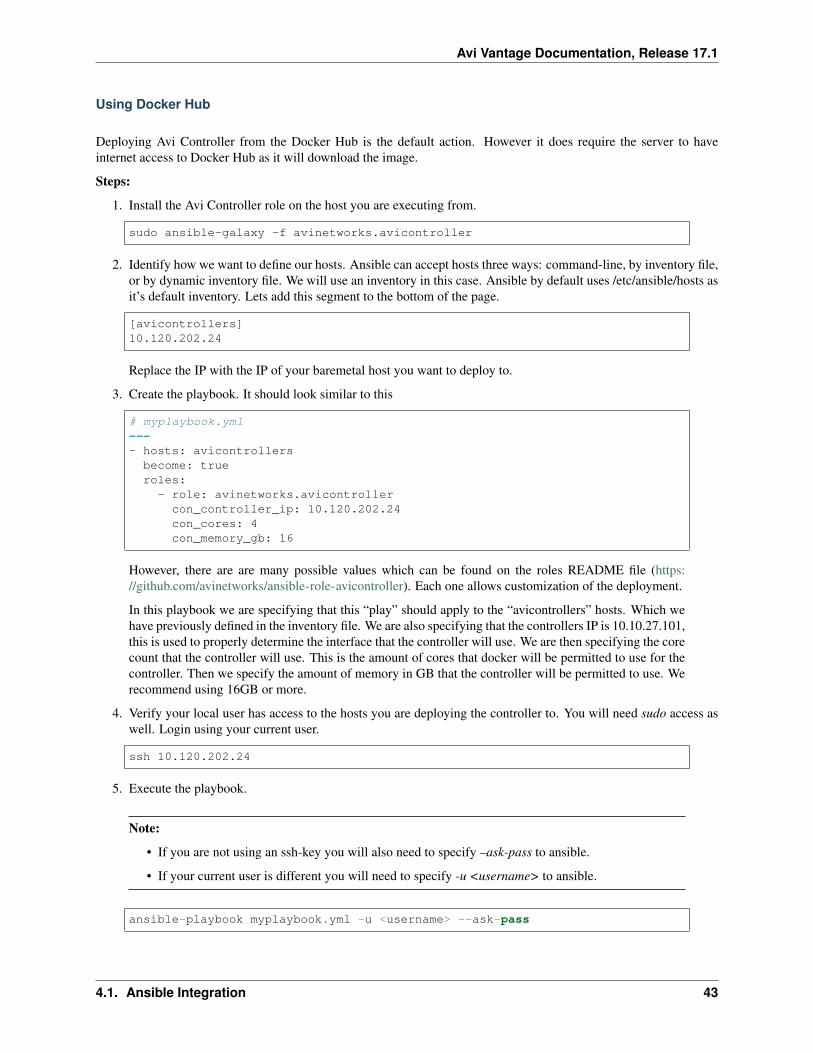
Avi Vantage Documentation, Release 17.1
Using Docker Hub
Deploying Avi Controller from the Docker Hub is the default action. However it does require the server to haveinternet access to Docker Hub as it will download the image.
Steps:
1. Install the Avi Controller role on the host you are executing from.
sudo ansible-galaxy -f avinetworks.avicontroller
2. Identify how we want to define our hosts. Ansible can accept hosts three ways: command-line, by inventory file,or by dynamic inventory file. We will use an inventory in this case. Ansible by default uses /etc/ansible/hosts asit’s default inventory. Lets add this segment to the bottom of the page.
[avicontrollers]10.120.202.24
Replace the IP with the IP of your baremetal host you want to deploy to.
3. Create the playbook. It should look similar to this
# myplaybook.yml---- hosts: avicontrollersbecome: trueroles:
- role: avinetworks.avicontrollercon_controller_ip: 10.120.202.24con_cores: 4con_memory_gb: 16
However, there are are many possible values which can be found on the roles README file (https://github.com/avinetworks/ansible-role-avicontroller). Each one allows customization of the deployment.
In this playbook we are specifying that this “play” should apply to the “avicontrollers” hosts. Which wehave previously defined in the inventory file. We are also specifying that the controllers IP is 10.10.27.101,this is used to properly determine the interface that the controller will use. We are then specifying the corecount that the controller will use. This is the amount of cores that docker will be permitted to use for thecontroller. Then we specify the amount of memory in GB that the controller will be permitted to use. Werecommend using 16GB or more.
4. Verify your local user has access to the hosts you are deploying the controller to. You will need sudo access aswell. Login using your current user.
ssh 10.120.202.24
5. Execute the playbook.
Note:
• If you are not using an ssh-key you will also need to specify –ask-pass to ansible.
• If your current user is different you will need to specify -u <username> to ansible.
ansible-playbook myplaybook.yml -u <username> --ask-pass
4.1. Ansible Integration 43
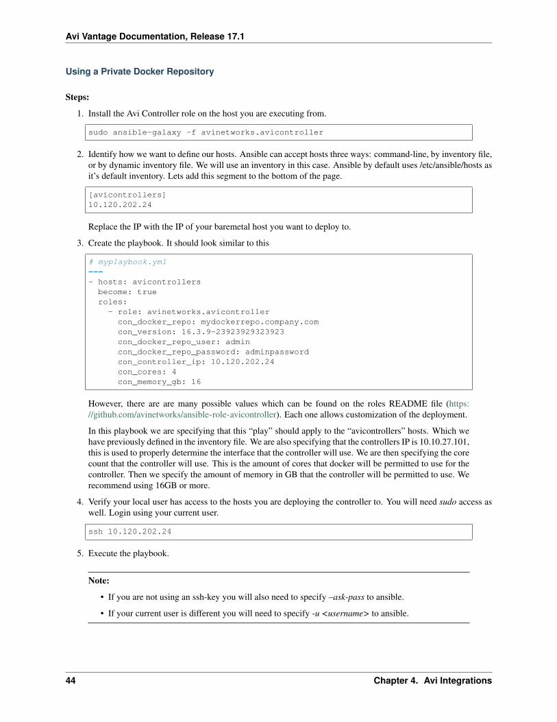
Avi Vantage Documentation, Release 17.1
Using a Private Docker Repository
Steps:
1. Install the Avi Controller role on the host you are executing from.
sudo ansible-galaxy -f avinetworks.avicontroller
2. Identify how we want to define our hosts. Ansible can accept hosts three ways: command-line, by inventory file,or by dynamic inventory file. We will use an inventory in this case. Ansible by default uses /etc/ansible/hosts asit’s default inventory. Lets add this segment to the bottom of the page.
[avicontrollers]10.120.202.24
Replace the IP with the IP of your baremetal host you want to deploy to.
3. Create the playbook. It should look similar to this
# myplaybook.yml---- hosts: avicontrollersbecome: trueroles:
- role: avinetworks.avicontrollercon_docker_repo: mydockerrepo.company.comcon_version: 16.3.9-23923929323923con_docker_repo_user: admincon_docker_repo_password: adminpasswordcon_controller_ip: 10.120.202.24con_cores: 4con_memory_gb: 16
However, there are are many possible values which can be found on the roles README file (https://github.com/avinetworks/ansible-role-avicontroller). Each one allows customization of the deployment.
In this playbook we are specifying that this “play” should apply to the “avicontrollers” hosts. Which wehave previously defined in the inventory file. We are also specifying that the controllers IP is 10.10.27.101,this is used to properly determine the interface that the controller will use. We are then specifying the corecount that the controller will use. This is the amount of cores that docker will be permitted to use for thecontroller. Then we specify the amount of memory in GB that the controller will be permitted to use. Werecommend using 16GB or more.
4. Verify your local user has access to the hosts you are deploying the controller to. You will need sudo access aswell. Login using your current user.
ssh 10.120.202.24
5. Execute the playbook.
Note:
• If you are not using an ssh-key you will also need to specify –ask-pass to ansible.
• If your current user is different you will need to specify -u <username> to ansible.
44 Chapter 4. Avi Integrations
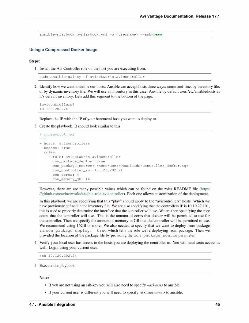
Avi Vantage Documentation, Release 17.1
ansible-playbook myplaybook.yml -u <username> --ask-pass
Using a Compressed Docker Image
Steps:
1. Install the Avi Controller role on the host you are executing from.
sudo ansible-galaxy -f avinetworks.avicontroller
2. Identify how we want to define our hosts. Ansible can accept hosts three ways: command-line, by inventory file,or by dynamic inventory file. We will use an inventory in this case. Ansible by default uses /etc/ansible/hosts asit’s default inventory. Lets add this segment to the bottom of the page.
[avicontrollers]10.120.202.24
Replace the IP with the IP of your baremetal host you want to deploy to.
3. Create the playbook. It should look similar to this
# myplaybook.yml---- hosts: avicontrollersbecome: trueroles:
- role: avinetworks.avicontrollercon_package_deploy: truecon_package_source: /home/user/Downloads/controller_docker.tgzcon_controller_ip: 10.120.202.24con_cores: 4con_memory_gb: 16
However, there are are many possible values which can be found on the roles README file (https://github.com/avinetworks/ansible-role-avicontroller). Each one allows customization of the deployment.
In this playbook we are specifying that this “play” should apply to the “avicontrollers” hosts. Which wehave previously defined in the inventory file. We are also specifying that the controllers IP is 10.10.27.101,this is used to properly determine the interface that the controller will use. We are then specifying the corecount that the controller will use. This is the amount of cores that docker will be permitted to use forthe controller. Then we specify the amount of memory in GB that the controller will be permitted to use.We recommend using 16GB or more. We also needed to specify that we want to deploy from packagevia con_package_deploy: true which tells the role we’re deploying from package. Then weprovided the location of the package file by providing the con_package_source parameter.
4. Verify your local user has access to the hosts you are deploying the controller to. You will need sudo access aswell. Login using your current user.
ssh 10.120.202.24
5. Execute the playbook.
Note:
• If you are not using an ssh-key you will also need to specify –ask-pass to ansible.
• If your current user is different you will need to specify -u <username> to ansible.
4.1. Ansible Integration 45
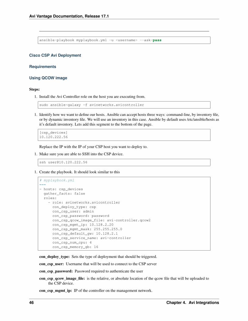
Avi Vantage Documentation, Release 17.1
ansible-playbook myplaybook.yml -u <username> --ask-pass
Cisco CSP Avi Deployment
Requirements
Using QCOW image
Steps:
1. Install the Avi Controller role on the host you are executing from.
sudo ansible-galaxy -f avinetworks.avicontroller
1. Identify how we want to define our hosts. Ansible can accept hosts three ways: command-line, by inventory file,or by dynamic inventory file. We will use an inventory in this case. Ansible by default uses /etc/ansible/hosts asit’s default inventory. Lets add this segment to the bottom of the page.
[csp_devices]10.120.222.56
Replace the IP with the IP of your CSP host you want to deploy to.
1. Make sure you are able to SSH into the CSP device.
1. Create the playbook. It should look similar to this
# myplaybook.yml---- hosts: csp_devicesgather_facts: falseroles:
- role: avinetworks.avicontrollercon_deploy_type: cspcon_csp_user: admincon_csp_password: passwordcon_csp_qcow_image_file: avi-controller.qcow2con_csp_mgmt_ip: 10.128.2.20con_csp_mgmt_mask: 255.255.255.0con_csp_default_gw: 10.128.2.1con_csp_service_name: avi-controllercon_csp_num_cpu: 4con_csp_memory_gb: 16
con_deploy_type: Sets the type of deployment that should be triggered.
con_csp_user: Username that will be used to connect to the CSP server
con_csp_password: Password required to authenticate the user
con_csp_qcow_image_file: is the relative, or absolute location of the qcow file that will be uploaded tothe CSP device.
con_csp_mgmt_ip: IP of the controller on the management network.
46 Chapter 4. Avi Integrations
Avi Vantage Documentation, Release 17.1
con_csp_mgmt_mask: Subnet mask that the controller will require.
con_csp_default_gw: Default gateway for the controller
con_csp_service_name: Name of the service to be created on the CSP
con_csp_num_cpu: Number of CPUs to be allocated to the Controller
con_csp_memory_gb: Amount of memory in GB allocated to the Controller
Note: There are are many possible values which can be found on the roles README file (https://github.com/avinetworks/ansible-role-avicontroller). Each one allows customization of the deployment.
In this playbook we are specifying that this “play” should apply to the “csp_devices” hosts. Anything notrequired mentioned here CSP Deployment Variables can be omitted from your role parameters. Defaultsare also noted on that document.
1. Execute the playbook.
Note:
• If you are not using an ssh-key you will also need to specify –ask-pass to ansible.
• If your current user is different you will need to specify -u <username> to ansible.
ansible-playbook myplaybook.yml -u <username> --ask-pass
Avi SE Role
Avi Docker Role
Avi Network Interfaces Role
Python SDK Integration
4.2. Python SDK Integration 47