Embed Size (px)
Citation preview

Aviation Department Building Information Modeling (BIM) Standard
Version 1
Last Updated: September 26, 2013
Prepared by:
No portion of this work may be reproduced without the express written
permission of the copyright holders. All rights reserved Broward County Aviation Department
Contents 1. Introduction ...................................................................................................................................................... 4
A. Broward County Aviation Department’s (BCAD) BIM Vision ....................................................................... 4
B. BCAD’s BIM Goals and Objectives ................................................................................................................ 4
C. Project Delivery & BIM ................................................................................................................................. 5
D. BCAD BIM Expectation and Uses of BIM by Department ............................................................................. 5
2. General Overview of Deliverables .................................................................................................................... 6
A. BIM Project Execution Plan (BIMPxP) .......................................................................................................... 8
B. Model Progression Schedule (MPS) ............................................................................................................. 9
C. 2D Contract Documents ............................................................................................................................... 9
D. Building Information Models - BIMs ............................................................................................................ 9
E. Construction Operations Building Information Exchange (COBie)............................................................. 10
3. Level of Development (LOD) vs. Level of Detail ............................................................................................. 11
A. LOD vs. Level of Detail ................................................................................................................................ 11
B. Level of Detail - Definition .......................................................................................................................... 11
C. LOD Definition ........................................................................................................................................... 11
4. Roles & Responsibilities.................................................................................................................................. 13
A. The Owner: BCAD ....................................................................................................................................... 13
B. Design Team ............................................................................................................................................... 14
C. Construction Team ..................................................................................................................................... 15
5. Formats and Approved Software ................................................................................................................... 16
A. Interoperability and Open Standards ......................................................................................................... 16
6. BIM Use Cases ................................................................................................................................................ 17
a) Marketing & Presentation .......................................................................................................................... 17
b) Space and Program Validation ................................................................................................................... 17
c) Energy Validation Analysis ......................................................................................................................... 17
d) Design Review ............................................................................................................................................ 17
e) Design for Maintenance (D4M) Review ..................................................................................................... 18
f) Spatial Coordination & Constructability Review ........................................................................................ 18
g) 4D Scheduling and Phasing......................................................................................................................... 18
No portion of this work may be reproduced without the express written permission of the copyright holders. All rights reserved Broward County Aviation Department
2
h) 5D Quantities and Cost Estimate Validation .............................................................................................. 19
i) Clash Detection and Coordination before Installation ............................................................................... 19
j) Shop Drawings, Sleeve Drawings and Fabrication ..................................................................................... 19
k) BIM in the field for Installation .................................................................................................................. 20
7. BIM Workflows and Deliverables During Design ............................................................................................ 21
A. BIM Scope & Modeling Extent ................................................................................................................... 21
C. Model Content Requirements .................................................................................................................... 21
D. Level of Detail per Discipline ...................................................................................................................... 22
E. BIM Workflows During Design ................................................................................................................... 23
F. BIM Collaboration and Model Sharing During Design ................................................................................ 24
G. Design Deliverables .................................................................................................................................... 24
8. BIM Workflows During the Bidding Phase ..................................................................................................... 26
9. BIM Workflows and Deliveries During Construction ...................................................................................... 27
A. Model Content Requirement ..................................................................................................................... 27
B. BIM Workflows During Construction ......................................................................................................... 27
10. Construction Operations Building Information Exchange (COBie) Workflow, Roles and Responsibilities and Deliverables ..................................................................................................................................................... 31
A. List of Assets requiring COBie Data Set ...................................................................................................... 31
B. Roles & Responsibilities.............................................................................................................................. 31
C. Classification tables .................................................................................................................................... 33
D. COBie Standard and BCAD specified data set ............................................................................................ 34
E. Best Practices ............................................................................................................................................. 36
F. COBie Progression Schedule (CPS) ............................................................................................................. 37
11. Appendix A – Sample BIMPxP .................................................................................................................... 42
12. Appendix B – Model Progression Schedule (MPS)- Available upon request in Excel Format. ................... 53
13. Glossary ...................................................................................................................................................... 57
14. Credits ........................................................................................................................................................ 60
No portion of this work may be reproduced without the express written permission of the copyright holders. All rights reserved Broward County Aviation Department
3
1. Introduction
A. Broward County Aviation Department’s (BCAD) BIM Vision With thousands of years of construction history, endless computing power and relentless advances in technology, the act of building in the twenty-first century ought to be done with optimum efficiency and the built environment operated and maintained with the same rigor.
The arrival of Building Information Modeling (BIM) in the built environment has enabled Designers and Constructors to not only virtualize their design solutions, but also simulate the act of building virtually, before a shovel is ever put in the ground. The term Virtual Design and Construction (VDC) was coined to help explain how designers and builders are now better able to more accurately predict the results of their work. Owners recognize the benefit of BIM and VDC as a risk mitigator and the industry is embracing and advancing BIM services as part of their standard practices.
BCAD believes in the BIM process and intends to make that process flexible for any and all parties tasked with designing and building its facilities by having clearly defined BIM deliverables. To that end BCAD has commissioned the development of this standard to plot the general requirements for BIM, while clearly stating BCAD’s BIM goals and objectives. Where applicable, BCAD will be aligning this Standard with the National Building Information Modeling Standard- United States, Version 2 (NBIMS-US v2).
B. BCAD’s BIM Goals and Objectives At a minimum BCAD wants to achieve the following goals and objectives: BIM as a planning tool; BIM as a visualization and communication tool during design, construction and operations; BIM as a program validation tool; BIM to generate construction documentation; BIM for constructability and maintainability review; BIM for coordination to minimize change orders due to field coordination; BIM for “As Constructed” validation for Operations; BIM and the use of the Construction Operations Building information exchange (COBie) from
design through construction to operations. BCAD understands that the benefits of BIM do not stop there and will be updating this Standard as new technology evolves. Additional goals and uses of BIM exist, and if so required, will be detailed in the RFP, RFQ, Contract and /or BIM Execution plan (BIMPxP).
BCAD understands that owners can efficiently repurpose the virtual information accumulated throughout the phases of design and construction in order to operate and maintain their buildings more efficiently throughout their lifecycle. The term Virtual Design Construction and Operation (VDCO) refers to the fact that Facility Managers are now able to use BIM to run their buildings at lower costs and for longer periods of time. BCAD’s goal is to leverage the benefits of BIM at the operation and maintenance levels by enabling its staff to quickly access the most relevant and accurate information
No portion of this work may be reproduced without the express written permission of the copyright holders. All rights reserved Broward County Aviation Department
4
about their buildings in order to perform their tasks and make better decisions efficiently. This standard is written to help achieve this goal.
C. Project Delivery & BIM BIM deliverables and VDCO workflow will change depending on the contracted project delivery method. It is not the Standard’s intent to define processes for each delivery method, but instead to define the minimum BIM deliverables that will be required. The Standard will define how BCAD plans to use the deliverables and will require that a BIM Project Execution Plan be created for each project. The BIMPxP shall be adapted to support the contract delivery method and specifically outline the BIM protocols, workflow, roles and responsibilities of each party.
D. BCAD BIM Expectation and Uses of BIM by Department BCAD has various departments/stakeholders throughout the organization that will need to access and use the BIM information during design, construction, project closeout and throughout occupancy. These stakeholders will need different sets of information and will use the information differently. Because of the various needs and uses, one of the objectives of this standard is to clarify what each group’s expectations are, what their use will be, and in what format they will need that information. By defining these uses, this allows the Design & Construction Teams and all BIM participants to plan for and prepare, accumulate, organize and deliver the information in a usable format to BCAD’s end users. Currently, the departments will be using the BIMs for viewing only. The following is a list of BCAD’s BIM Expectations by Department: o Planning Department
The BIMs may be used for: Space Planning & Analysis Way finding Feasibility studies Gate parking and airspace studies GIS data input management
o Business and Property Management Division Tenant / Leasing contracts exhibits
o Facilities Management Department The BIMs may be used for:
BIM data will be integrated into BCAD’s Facilities Computerized Maintenance Management System (CMMS) through a COBie deliverables for use in the following: o Preventative Maintenance o Corrective Maintenance o Scheduled Inspections o Asset Management
No portion of this work may be reproduced without the express written permission of the copyright holders. All rights reserved Broward County Aviation Department
5
o Finance & Procurement The BIMs may be used for: Pay application justification Change Order clarification
o Security The BIMs may be used for: Spatial location and “views” of all cameras and security access readers Inventory and mapping of security equipment
o GIS The BIMs may be used for: Spatial location and information of all infrastructure utilities
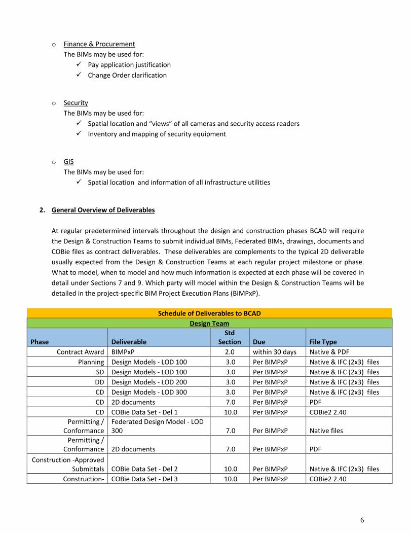
2. General Overview of Deliverables At regular predetermined intervals throughout the design and construction phases BCAD will require the Design & Construction Teams to submit individual BIMs, Federated BIMs, drawings, documents and COBie files as contract deliverables. These deliverables are complements to the typical 2D deliverable usually expected from the Design & Construction Teams at each regular project milestone or phase. What to model, when to model and how much information is expected at each phase will be covered in detail under Sections 7 and 9. Which party will model within the Design & Construction Teams will be detailed in the project-specific BIM Project Execution Plans (BIMPxP).
Schedule of Deliverables to BCAD Design Team
Phase Deliverable Std
Section Due File Type Contract Award BIMPxP 2.0 within 30 days Native & PDF
Planning Design Models - LOD 100 3.0 Per BIMPxP Native & IFC (2x3) files SD Design Models - LOD 100 3.0 Per BIMPxP Native & IFC (2x3) files DD Design Models - LOD 200 3.0 Per BIMPxP Native & IFC (2x3) files CD Design Models - LOD 300 3.0 Per BIMPxP Native & IFC (2x3) files CD 2D documents 7.0 Per BIMPxP PDF CD COBie Data Set - Del 1 10.0 Per BIMPxP COBie2 2.40
Permitting / Conformance
Federated Design Model - LOD 300 7.0 Per BIMPxP Native files
Permitting / Conformance 2D documents 7.0 Per BIMPxP PDF
Construction -Approved Submittals COBie Data Set - Del 2 10.0 Per BIMPxP Native & IFC (2x3) files
Construction- COBie Data Set - Del 3 10.0 Per BIMPxP COBie2 2.40
No portion of this work may be reproduced without the express written permission of the copyright holders. All rights reserved Broward County Aviation Department
6
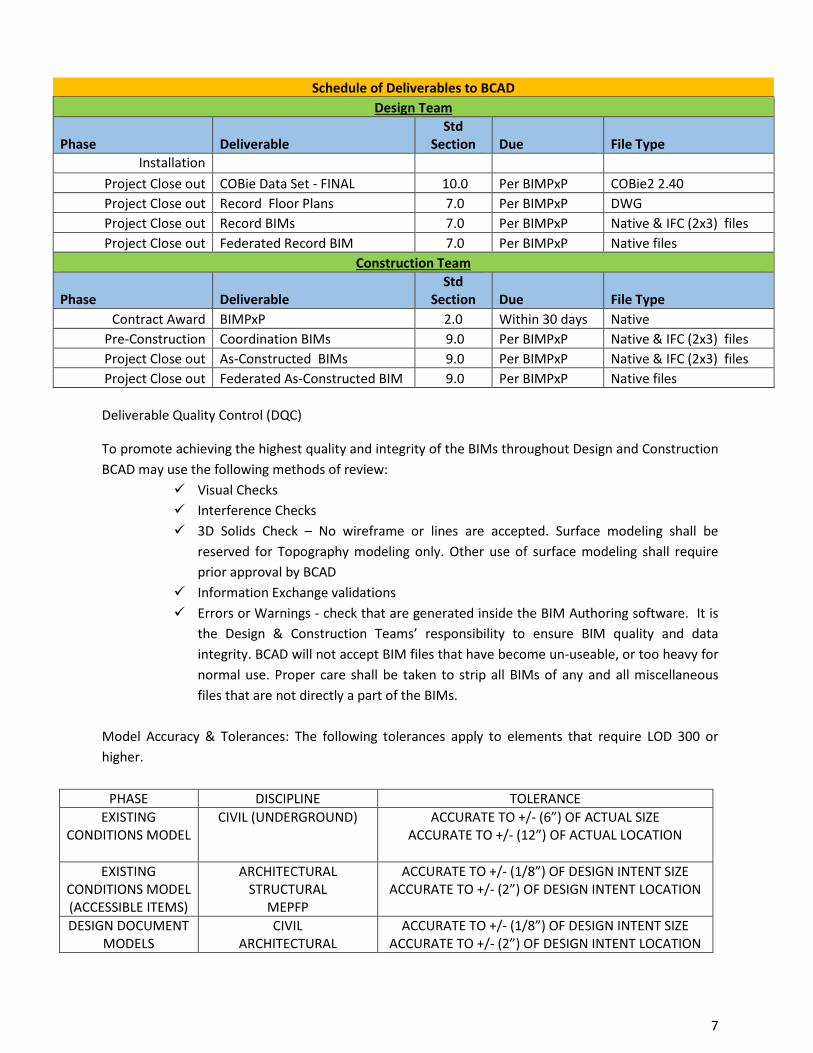
Schedule of Deliverables to BCAD Design Team
Phase Deliverable Std
Section Due File Type Installation
Project Close out COBie Data Set - FINAL 10.0 Per BIMPxP COBie2 2.40 Project Close out Record Floor Plans 7.0 Per BIMPxP DWG Project Close out Record BIMs 7.0 Per BIMPxP Native & IFC (2x3) files Project Close out Federated Record BIM 7.0 Per BIMPxP Native files
Construction Team
Phase Deliverable Std
Section Due File Type Contract Award BIMPxP 2.0 Within 30 days Native
Pre-Construction Coordination BIMs 9.0 Per BIMPxP Native & IFC (2x3) files Project Close out As-Constructed BIMs 9.0 Per BIMPxP Native & IFC (2x3) files Project Close out Federated As-Constructed BIM 9.0 Per BIMPxP Native files
Deliverable Quality Control (DQC)
To promote achieving the highest quality and integrity of the BIMs throughout Design and Construction BCAD may use the following methods of review:
Visual Checks Interference Checks 3D Solids Check – No wireframe or lines are accepted. Surface modeling shall be
reserved for Topography modeling only. Other use of surface modeling shall require prior approval by BCAD
Information Exchange validations Errors or Warnings - check that are generated inside the BIM Authoring software. It is
the Design & Construction Teams’ responsibility to ensure BIM quality and data integrity. BCAD will not accept BIM files that have become un-useable, or too heavy for normal use. Proper care shall be taken to strip all BIMs of any and all miscellaneous files that are not directly a part of the BIMs.
Model Accuracy & Tolerances: The following tolerances apply to elements that require LOD 300 or higher.
PHASE DISCIPLINE TOLERANCE EXISTING
CONDITIONS MODEL CIVIL (UNDERGROUND) ACCURATE TO +/- (6”) OF ACTUAL SIZE
ACCURATE TO +/- (12”) OF ACTUAL LOCATION
EXISTING CONDITIONS MODEL (ACCESSIBLE ITEMS)
ARCHITECTURAL STRUCTURAL
MEPFP
ACCURATE TO +/- (1/8”) OF DESIGN INTENT SIZE ACCURATE TO +/- (2”) OF DESIGN INTENT LOCATION
DESIGN DOCUMENT
MODELS CIVIL
ARCHITECTURAL ACCURATE TO +/- (1/8”) OF DESIGN INTENT SIZE
ACCURATE TO +/- (2”) OF DESIGN INTENT LOCATION
No portion of this work may be reproduced without the express written permission of the copyright holders. All rights reserved Broward County Aviation Department
7
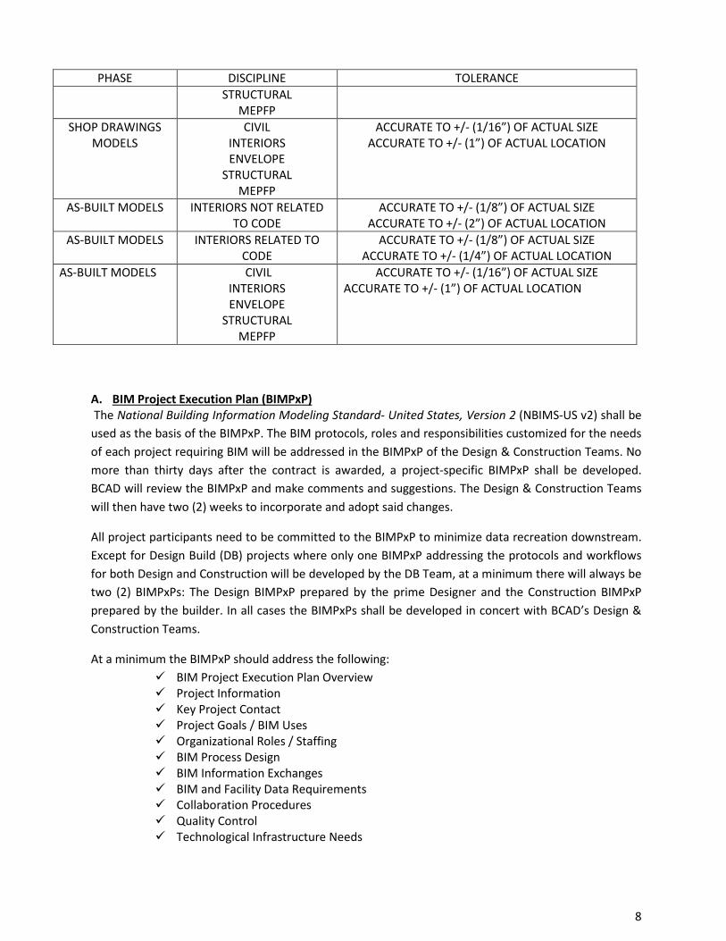
PHASE DISCIPLINE TOLERANCE STRUCTURAL
MEPFP
SHOP DRAWINGS MODELS
CIVIL INTERIORS ENVELOPE
STRUCTURAL MEPFP
ACCURATE TO +/- (1/16”) OF ACTUAL SIZE ACCURATE TO +/- (1”) OF ACTUAL LOCATION
AS-BUILT MODELS INTERIORS NOT RELATED TO CODE
ACCURATE TO +/- (1/8”) OF ACTUAL SIZE ACCURATE TO +/- (2”) OF ACTUAL LOCATION
AS-BUILT MODELS INTERIORS RELATED TO CODE
ACCURATE TO +/- (1/8”) OF ACTUAL SIZE ACCURATE TO +/- (1/4”) OF ACTUAL LOCATION
AS-BUILT MODELS CIVIL INTERIORS ENVELOPE
STRUCTURAL MEPFP
ACCURATE TO +/- (1/16”) OF ACTUAL SIZE ACCURATE TO +/- (1”) OF ACTUAL LOCATION
A. BIM Project Execution Plan (BIMPxP) The National Building Information Modeling Standard- United States, Version 2 (NBIMS-US v2) shall be used as the basis of the BIMPxP. The BIM protocols, roles and responsibilities customized for the needs of each project requiring BIM will be addressed in the BIMPxP of the Design & Construction Teams. No more than thirty days after the contract is awarded, a project-specific BIMPxP shall be developed. BCAD will review the BIMPxP and make comments and suggestions. The Design & Construction Teams will then have two (2) weeks to incorporate and adopt said changes.
All project participants need to be committed to the BIMPxP to minimize data recreation downstream. Except for Design Build (DB) projects where only one BIMPxP addressing the protocols and workflows for both Design and Construction will be developed by the DB Team, at a minimum there will always be two (2) BIMPxPs: The Design BIMPxP prepared by the prime Designer and the Construction BIMPxP prepared by the builder. In all cases the BIMPxPs shall be developed in concert with BCAD’s Design & Construction Teams.
At a minimum the BIMPxP should address the following: BIM Project Execution Plan Overview Project Information Key Project Contact Project Goals / BIM Uses Organizational Roles / Staffing BIM Process Design BIM Information Exchanges BIM and Facility Data Requirements Collaboration Procedures Quality Control Technological Infrastructure Needs
No portion of this work may be reproduced without the express written permission of the copyright holders. All rights reserved Broward County Aviation Department
8
Model Structure Project Deliverables Delivery Strategy / Contract
A sample BIMPxP is included in Appendix A of this document. The National Building Information Modeling Standard- United States, Version 2 (NBIMS-US v2) has a guide that outlines four (4) necessary steps to create a BIMPxP. These must be met at a minimum. They are as follows:
1.) Confirm goals and high value BIM uses during each project phase 2.) Design the BIM execution process 3.) Define the BIM deliverables in the form of information exchanges 4.) Develop the infrastructure to support the implementation, such as contracts,
communication procedures, technology and quality control B. Model Progression Schedule (MPS) A Model Progression Schedule shall be used as a tool to help Model Contributors throughout the Design, Construction and Operation phases understand what should be included in the BIMs when at each project milestone. The MPS shall be based on the CSI’s OmniClass Table 22 Work Results, formerly known as MasterFormat, the version currently in the NIBMS-US Standard. It shall be the responsibility of the Design & Construction Teams to tailor the MPS to meet the requirements of this standard and their project-specific needs. An MPS shall be submitted along with the BIMPxP for review by BCAD. You will find a sample MPS in Appendix B of this document. C. 2D Contract Documents To promote efficiency and continuity, the 2D construction documents must be extracted directly from the Design BIMs and both the BIMs and the 2D Deliverables will be integral parts of the contract documents. Two dimensional (2D) details, enlargements, General Notes, externally-generated Schedules, and specifications will take precedence over the Design BIMs. BCAD expects 2D Deliverables, namely Site Plans, Plans, Sections, Elevations and the Schedules typically found in construction documents to be extracted directly from the BIMs. The BIMs shall include all elements and information needed to produce Permit Documents for Design Intent, Shop Drawings for Construction installation, Record BIM As-Built, and COBie data sets. D. Building Information Models - BIMs Overview of BIM Deliverables: This Standard will strive to clarify what BCAD expects from the BIMs in terms of the Level of Detail, Level of Development, Model Content Requirements and Level of Coordination at each phase. At a minimum, three (3) types of BIM deliverables will be produced by the BIM process:
1. Design BIMs 2. Construction BIMs 3. Federated BIMs
No portion of this work may be reproduced without the express written permission of the copyright holders. All rights reserved Broward County Aviation Department
9
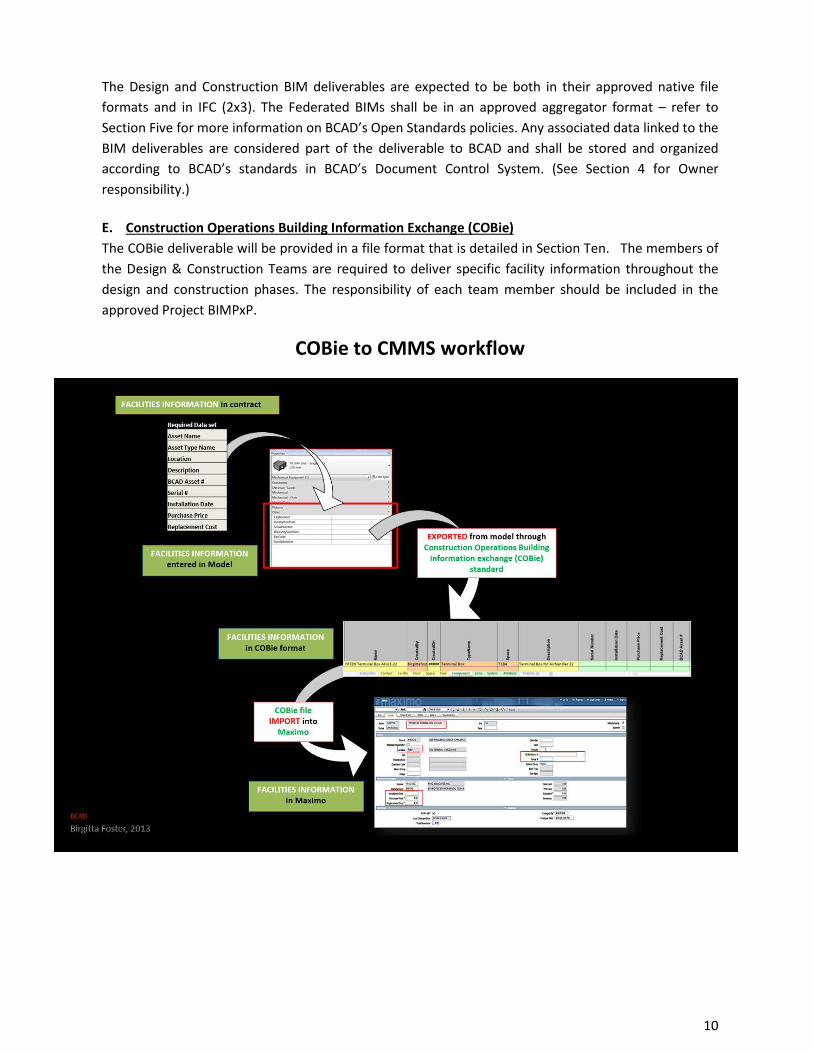
The Design and Construction BIM deliverables are expected to be both in their approved native file formats and in IFC (2x3). The Federated BIMs shall be in an approved aggregator format – refer to Section Five for more information on BCAD’s Open Standards policies. Any associated data linked to the BIM deliverables are considered part of the deliverable to BCAD and shall be stored and organized according to BCAD’s standards in BCAD’s Document Control System. (See Section 4 for Owner responsibility.) E. Construction Operations Building Information Exchange (COBie) The COBie deliverable will be provided in a file format that is detailed in Section Ten. The members of the Design & Construction Teams are required to deliver specific facility information throughout the design and construction phases. The responsibility of each team member should be included in the approved Project BIMPxP.
COBie to CMMS workflow
No portion of this work may be reproduced without the express written permission of the copyright holders. All rights reserved Broward County Aviation Department
10
3. Level of Development (LOD) vs. Level of Detail A. LOD vs. Level of Detail When talking about Level of Detail one generally refers to an object, while Level of Development is generally referred to when evaluating the reliability of the information contained in a building system or a discipline as relevant to a specific BIM Use Case. For example, a low level of detail object can be part of an LOD 500 BIM. B. Level of Detail - Definition Level of Detail refers to the amount of aggregated parts included in the modeling of an individual component, assembly or object. BCAD will recognize two Levels of Detail: High and Low. The Level of Detail of components within the BIMs will be discussed in Section Seven & Nine. To avoid confusion when discussing Level of Detail no abbreviations will be used.
For the purposes set forth in this standard LOD will always mean Level of Development. BCAD will adopt the definitions established by the BIMForum’s 2013 Draft LOD Specification. C. LOD Definition The AIA describes the concept of LOD as an identification of the “…specific minimum content requirements and associated Authorized Uses for each Model Element at [six] progressively detailed levels of completeness.” Following are the Fundamental LOD Definitions: o LOD 100 – Conceptual
“The Model Element may be graphically represented in the Model with a symbol or other generic representation, but does not satisfy the requirements for LOD 200. Information related to the Model Element (i.e. cost per square foot, tonnage of HVAC, etc.) can be derived from other Model Elements.”
o LOD 200 – Generic Placeholders “The Model Element is graphically represented within the Model as a generic system, object, or assembly with approximate quantities, size, shape, location, and orientation. Non-graphic information may also be attached to the Model Element.”
o LOD 300 – Specific Assemblies “The Model Element is graphically represented within the Model as a specific system, object or assembly in terms of quantity, size, shape, location, and orientation. Non-graphic information may also be attached to the Model element.”
o LOD 350 – Hybrid of Specific & Detailed Assemblies “The Model Element is graphically represented within the Model as a specific system, object or assembly in terms of size, shape, location, orientation and interfaces with
No portion of this work may be reproduced without the express written permission of the copyright holders. All rights reserved Broward County Aviation Department
11
other building systems. Non-graphic information may also be attached to the Model Element.”
o LOD 400 – Detailed Assemblies “The Model Element is graphically represented within the Model as a specific system, object or assembly in terms of size, shape, location, quantity, and orientation with detailing, fabrication assembly, and installation information. Non-graphic information may also be attached to the Model Element.”
o LOD 500 – As-Built “The Model Element is a field-verified representation in terms of size, shape, location, quantity, and orientation. Non-graphic information may also be attached to the Model Elements.”
BCAD acknowledges that there isn’t a strict equivalence between a BIM’s LOD and its project phase; however BCAD intends to clearly define what the minimum modeling content expectation is at each project phase. See Sections Seven & Nine for expected LOD at each project phase.
No portion of this work may be reproduced without the express written permission of the copyright holders. All rights reserved Broward County Aviation Department
12
4. Roles & Responsibilities
A. The Owner: BCAD BCAD will assume the roles reserved for owners under the terms and conditions of the governing contract for each project. This Standard does not supersede or circumvent in any way those obligations. The intent of this section is to inform the Design and Constructions Teams of BCAD’s means of distributing, collecting and verifying the BIM information for each project. BCAD’s roles and responsibilities as related to BIM include, and are not limited to, the following: BCAD’s Information Manager (IM) BCAD’s IM works with BCAD’s Information Technology (IT) officers to grant controlled access to the BIMs to BCAD’s Project Managers for the duration of their projects. It is also the IM’s responsibility to manage and grant access to all BCAD’s Departments and Staff.
BCAD’s Project Manager (PM) BCAD’s PMs will receive from the IM the procedure on how to access and view models. The Design & Construction Teams are responsible for managing their own secured information exchange systems for the duration of the project or until their BIMs have been accepted as complete by the owner. BCAD shall be given access to such system as part of the Design & Construction Teams participants. BCAD’s BIM Controller The BIM Controller’s role is to ensure that BCAD’s BIM Standards are being implemented through all the Capital Improvement Projects (CIP) and may be an internal position or a third-party provider. The BIM Controller gets access to the BIMs from the IM. The BIM Controller is not responsible for managing and maintaining the Federated Design or Construction BIMs; that responsibility lies with the Design Team on the project during the Design phases and the Construction Team during Construction. It is up to the Design & Construction Team to comply and deliver the BIMs to BCAD. BCAD’s responsibilities as it relates to BIM include, but are not limited to, the following: BCAD’s Document Control System BCAD’s Document Control Team manages construction related information for both paper and electronic documents. At the request of BCAD, the Information System Team (IST) creates project folders within BCAD’s Information System for the purpose of sharing electronic information while the project is ‘active’, i.e. during the Design or Construction Phases. BCAD’s Information Manager (IM) also uses Microsoft SharePoint to manage non-active electronic files where no bidirectional sharing is required. SharePoint is mostly used for static record documents. Request For Proposals (RFP) & Request for Qualifications (RFQ) BCAD will use this BIM Standard as an addendum in all of its RFPs / RFQs. Higher consideration will be given to Design & Construction Teams with prior BIM project experience. The lack of BIM experience on Design & Construction Teams will not be a disqualifier. A thorough understanding of the BIM process,
No portion of this work may be reproduced without the express written permission of the copyright holders. All rights reserved Broward County Aviation Department
13
as it applies to BCAD and this Standard, is a minimum qualifier and must be demonstrated in order to meet BCAD’s BIM prequalification standards. BIMs Ownership and Data Reuse BCAD and the project BIM contributors have ownership of all BIMs, CAD Files, COBie Data and their associated 2D Deliverables which will be defined in the governing contract for each project. Reuse of the BIMs will also be defined in the governing contract. BCAD recognizes the need for downstream users of the electronic media hold harmless the authors of the media against any and all harm and liability caused by the use of such media being either corrupt, or used in a manner not intended by the author. Legacy Information BCAD will make available through their Document Control System any and all project-related information to the Design & Construction Teams in whatever medium that is readily available. Such information may include, and is not limited to:
1) Record drawings and As-Built files. Record drawings and As-built files will be made available whenever possible. Such files may be found in any formats, including but not limited to PDF, TIFF, CAD, or BIM.
2) GIS Utility Atlas. The utility Atlas and BCAD’s GIS Standards will be made available to the Civil Engineering team when applicable.
3) Laser Scans in raw formats will be provided should they exist. If needed, the 3D byproduct model of the Point Clouds is the responsibility of the Design & Construction Teams. If a valid 3D by-product model already exists BCAD will make it available. The placement and use, when available, of such information will be established by the project BIMPxP.
4) Master Site BIM Depending on the project a Master Site BIM may be available. When that is the case BCAD will share the model and project-shared coordinates so that any and all new project BIMs will be properly placed and located within the Master Site BIM. It is critical that all BIMs created by the Design & Construction Teams throughout Design and Construction match their corresponding coordinates inside the Master Site BIM.
B. Design Team Design Project Manager (PM) The Project Manager is the ultimate point of contact for the overall project. The individual can serve as the BIM Manager if he/she has the relevant BIM experience depending on the size and complexity of the project. Design BIM PM (BPM) The design team shall have a dedicated Project BIM Manager that has sufficient experience for the size and complexity of the project and shall be proficient in the authoring and coordination of BIMs. This individual will serve as the main point of contact for project-related BIM & VDC information.
No portion of this work may be reproduced without the express written permission of the copyright holders. All rights reserved Broward County Aviation Department
14
This Design BIM PM shall be qualified enough to implement the Design BIMPxP and interface with outside BIM stakeholders including using BCAD’s Document Control System. Those stakeholders will include, at a minimum, BCAD’s PM and BIM Controller, but may also include various BCAD’s end user groups, and the Contractor and its subcontractors when they are already known and are a part of the Design & Construction Teams.
COBie Coordinator The COBie Coordinator will be responsible for the COBie process including assigning room information in the Architectural model. All other project models using room information must reference the room information assigned in the Architectural model. This will ensure the proper location information is provided in the COBie deliverable. If the case where room-naming conventions are provided by BCAD, the room names must be strictly enforced in the COBie deliverables. C. Construction Team Construction PM (PM) The Project Manager is the ultimate point of contact for the overall project. This individual can also serve as the BIM Manager for the project if he/she has the relevant BIM experience with the size and complexity of the project. Construction BIM PM (BPM) The Construction team shall have a dedicated BIM PM to the project that has sufficient experience for the size and complexity of the project and shall be proficient in the management of project BIMs. This individual will serve as the main point of contact for BIM & VDCO. The Construction BIM PM shall be qualified to implement the Construction BIMPxP and interface with outside BIM stakeholders including using BCAD’s Document Control System. COBie Coordinator The COBie Constructor Coordinator will be responsible for coordinating the COBie process with the design team’s COBie Coordinator and for completing his/her assigned portion of the COBie deliverable including serial number and installation date.
No portion of this work may be reproduced without the express written permission of the copyright holders. All rights reserved Broward County Aviation Department
15
5. Formats and Approved Software
A. Interoperability and Open Standards The Design & Construction Teams are required to use parametric BIM Authoring software on all new construction and renovation projects unless otherwise specified. BCAD requires Industry Foundation Class (IFC 2x3) compliant BIM Authoring software. For a complete list of IFC (2x3) compliant Software please visit: http://www.buildingsmart-tech.org
Interoperability allows team members from different disciplines to work in different BIM authoring platforms through IFC (2x3), or direct native imports. When more than one software is being used to produce CD’s, the Design Team shall take proper care to keep consistency in drafting standards, measurements etc., throughout the Construction Document set. Additionally, all BIM's regardless of authoring platform shall share coordinates to ensure proper placement both relative to each other, but also in relation to the Master Site BIM when one exists. All BIMs regardless of platform shall be the same scale and unless other requirements govern, in Imperial units. In every phase, the BIMs shall be managed, aggregated and coordinated in a single, centralized database resulting in an accurate Federated BIM. The files must be delivered in these formats: 3D - Formats: Native Formats & IFC (2x3) 2D - Formats: Native Format where applicable and vector PDFs. Examples of acceptable IFC compliant software and formats are as follows:
BIM Authoring For Design: Allplan Architecture/ Engineering, ArchiCAD, AutoCAD Civil 3D, AutoCAD Architecture / MEP, Bentley Architecture V8i, Bentley Building Electrical / Mechanical / Structural Systems V8i, Digital Project, Revit, Tekla Structures, Vectorworks In addition to the software listed above, additional BIM Authoring tools for Construction: CAD-Duct, SDS/2 BIM Managing Software for Design and Construction: Bentley Navigator, BIM 360 Glue, Navisworks, Solibri Model Checker, Tekla BIMSight, Vico
Software that is not listed above will need to be submitted to BCAD for approval prior to use.
No portion of this work may be reproduced without the express written permission of the copyright holders. All rights reserved Broward County Aviation Department
16
6. BIM Use Cases The RFP, BIMPxP and other contract document may request the following BIM Use Cases:
a) Marketing & Presentation While accepted BIM Authoring software shall be used to create the BIMs, it is understood that further development of the models may need to occur outside of the BIM Authoring software in order to create marketing material.
b) Space and Program Validation The Design Team shall implement an iterative BIM-enabled process to validate their adherence to the Program in terms of Space and Equipment. That process can be established using the BIM authoring software being used to produce the design, or it can be done using specialized Program Validation software that utilizes the Design BIMs to validate adherence to the program. The Design Team shall disclose the specifics of what software and format(s) will be used to perform Program Validation when putting together the Design BIMPxP.
c) Energy Validation Analysis The Designer and Construction Teams shall extract relevant data directly from the BIMs to perform energy simulation and life cycle cost calculations to validate their energy modeling. Proper modeling techniques shall be used with environmental parameters. The Design and Construction Teams shall disclose the specifics of what software format(s) will be used to perform the Energy Validation Analysis when putting together the BIMPxP.
d) Design Review The BIMs shall be used to communicate the intent and workability of the proposed design solutions in various ways and through various means to project stakeholders including BCAD, end users, maintenance officials and financial stakeholders. BCAD encourages the Design & Construction Teams to find efficient and effective ways to communicate their intent using BIM. At a minimum, the BIMs shall be used for design reviews, submittals, and construction documents. The Design and Construction Teams shall identify what specific means of visualization will be used for design review and review submittals when putting together the BIMPxP. Those means may include, but would not be limited to, the following:
Images (Screen Shots, Renderings) Animations (Fly-through, Panoramic immersion) Federated BIMs in a Read-only format. It is the Design & Construction Team’s responsibility
to make a free viewer available to the user.
Special consideration shall be given to security, safety and maintenance issues. At a minimum visualization strategies shall be used to help analyze the following areas and needs:
Egress and other life safety related circulation
No portion of this work may be reproduced without the express written permission of the copyright holders. All rights reserved Broward County Aviation Department
17
Location of Exit Signs and Strobe Lights Security Check Points Kiosk Design
e) Design for Maintenance (D4M) Review Using a Federated BIM, the Designer and Construction teams shall demonstrate there is sufficient access to perform proper maintenance activities on building systems and their associated components. D4M reviews differ from constructability reviews as they seek to ensure that elements surrounding these components do not hinder accessibility to safely perform scheduled or corrective maintenance activities.
The schedule of when these reviews take place will be defined in the BIMPxP, but at a minimum the Design and Construction Teams will incorporate them into constructability reviews. Reviews should address access at a minimum: all asset types requiring COBie data set deliverables. Although some elements may be closely located to components, BCAD may deem the restricted clearance allowable. This shall not be in conflict with any code required clearances. Review meetings where the Design & Construction Teams invite BCAD are expected at least once during DD and CD phases and at least once during construction.
f) Spatial Coordination & Constructability Review Spatial coordination means coordination between systems and components in the Design & Construction BIMs appropriate to the design and construction phases. This process differs from Clash Detection in that clashes may be deemed allowable by the Design Team depending on what systems are conflicting. Clashes are not acceptable during Construction. The Design and Construction Teams shall assure constructability by using a Federated Design BIM. A constructability review meeting where the Design & Construction Teams invite BCAD to participate is expected at least once during DD and CD phases and throughout construction.
g) 4D Scheduling and Phasing When continuous operations must be maintained in areas where construction is occurring, a clear phasing plan is often required. 4D scheduling and phasing is a tool to visually to show how construction of the proposed project will not disrupt current processes and operations. BCAD may request this service should they feel it necessary in complex project phasing.
The video clip of the 4D shall be produced in a 4D specialized software by combining a schedule with the BIMs and in a format viewable over the web such as MP4 or WMV; other formats can be suggested. The Design & Construction Teams will share the 4D model in a read-only, view-only format. It is the Design and Construction Team’s responsibility when sharing the 4D Model to ensure that it is in a format that can be opened by a free viewer.
If required by BCAD, the scope and LOD of the 4D shall be clearly defined in the Design or Construction BIMPxP.
Potential use per design phase
No portion of this work may be reproduced without the express written permission of the copyright holders. All rights reserved Broward County Aviation Department
18
a) Planning – Feasibility study. b) SD – Major Project Milestone and staging. c) DD – Building Structure and Systems. d) CD – Building complete with all systems and components.
Potential 4D uses during Construction are as follows:
a) Full Project Schedule b) Look ahead Schedule c) As-Planned vs. As Built Schedule d) Procurement Tracking e) Construction Sequence Analysis f) Safety Management g) Operational Impact
h) 5D Quantities and Cost Estimate Validation If required by BCAD, at the Schematic Design (SD) phase given the low level of development of the BIMs, it is understood that any 5D use shall be at a macro level and used as a validator for Probable Cost Estimates. As the BIMs LOD progress through the design phases, the Design Team shall use the quantities in the BIMs as a validator for their Estimates. It will be the responsibility of the Design Team to specify when they are writing the BIMPxP what method and software they will use to perform this task.
a) Planning – Probable Cost b) SD – Probable Cost & quantity Takeoff based on Square Footage c) DD – Probable Cost & quantity Takeoff based on available BIMs at LOD 200 d) CD – Probable Cost & quantity Takeoff based on available BIMs at LOD 300
i) Clash Detection and Coordination before Installation It is the Construction Teams responsibility to ensure that Clash Detection and Coordination is used to the fullest extent in order to avoid any problems during installation. BCAD will not accept change orders due to failed construction BIM coordination. Coordination shall be complete and the Construction Federated BIM shall show zero non-justified clashes between the Building components.
j) Shop Drawings, Sleeve Drawings and Fabrication
a) Shop drawings Shop Drawings shall be produced directly from the construction BIMs. No parallel 2D process will be accepted
b) Sleeve Drawings Sleeve drawings for cast-in-place or precast systems shall be produced after BIM Coordination is completed for the area of construction requiring the sleeve drawings.
c) Fabrication & Preassembly Whenever possible the Construction Team shall use the Construction BIMs to fabricate or preassemble their systems.
No portion of this work may be reproduced without the express written permission of the copyright holders. All rights reserved Broward County Aviation Department
19
k) BIM in the field for Installation The GC shall take measures to assure that what is being installed at the field is what was agreed upon on the Coordinated Federated Construction BIM. Any deviations must be documented as updates to the BIMs and the party responsible for resulting conflicts will be liable for costs associated with such deviations. l) BIM for GIS BCAD is currently developing a utility Atlas in GIS. Where applicable in new construction and renovation projects the Civil Engineer should produce their utility scope in BIM and deliver a GIS compliant model to BCAD. The model shall carry all attributes and/or object data necessary for GIS integration. It is the responsibility of the Architect, Civil engineer or General Contractor to request the GIS Standard from BCAD.
No portion of this work may be reproduced without the express written permission of the copyright holders. All rights reserved Broward County Aviation Department
20
7. BIM Workflows and Deliverables During Design A. BIM Scope & Modeling Extent The Design Team is expected to create a Design Intent model that is accurate and detailed to an LOD of 300. The Construction Document set must be produced directly from the Design BIMs. The expectation from BCAD is that designers use BIM whenever possible and as applicable. The modeling scope will typically include Civil, Site work, Architectural, Structural, Mechanical, Electrical, Plumbing, Fire Suppression, Signage, Baggage Handling and Passenger Loading bridges as applicable to the project. In addressing, adjacent boundaries all relevant contextual structures adjacent to, or in the vicinity of the scope of work shall be massed. The BIMPxP shall address the extent of modeling on existing conditions.
B. Timing of Delivery It will be up to BCAD and the Design Team to tailor their BIMPxP to accommodate the timing of the deliverables needed for their particular type of contract. BCAD expects, regardless of the LOD, that the content of the BIMs inside the Federated BIM, regardless of LOD be exclusionary and unique, i.e. no redundant elements shall exist across BIM contribution inside the Federated BIM.
C. Model Content Requirements Minimum LOD per Phase: A common practice to help designers know what to include in their models at each phase is that when the model is cut in plan or section the BIM should have as much information as traditionally seen in plan and section on 2D documents for that phase.
When generating 2D details, it is acceptable to overlay 2D graphics on BIM-generated views. This practice is only acceptable on enlarged plans, sections and details at scales of ½” or greater. Typical Detail can be 2D-drafted elements, but shall be created in the native BIM Authoring software and properly referenced to the model region it represents. BCAD acknowledges that there is not a strict equivalence between a BIM’s LOD and its project phases, however in general the model progression through the design phases shall be as follows:
Planning – Min. LOD 100
SD – Min. LOD 100 DD – Min. LOD 200 CD – Min. LOD 300
BCAD will define the minimum BIM content expectation for CD’s at an LOD 300. It is the responsibility of the Design Team to use the MPS as part of the Design BIMPxP to establish how they progressively reach BCAD’s expectation of the Level of Detail at LOD 300. Any model contribution that is not included
No portion of this work may be reproduced without the express written permission of the copyright holders. All rights reserved Broward County Aviation Department
21
within a specific discipline’s scope shall be the responsibility of the prime contract holder to take measures to assure the Design BIMs are complete. Section Three addresses this minimum requirement. The Design Team will update the models with all changes that may occur due to requests an comments from Authorities Having Jurisdiction (AHJ).
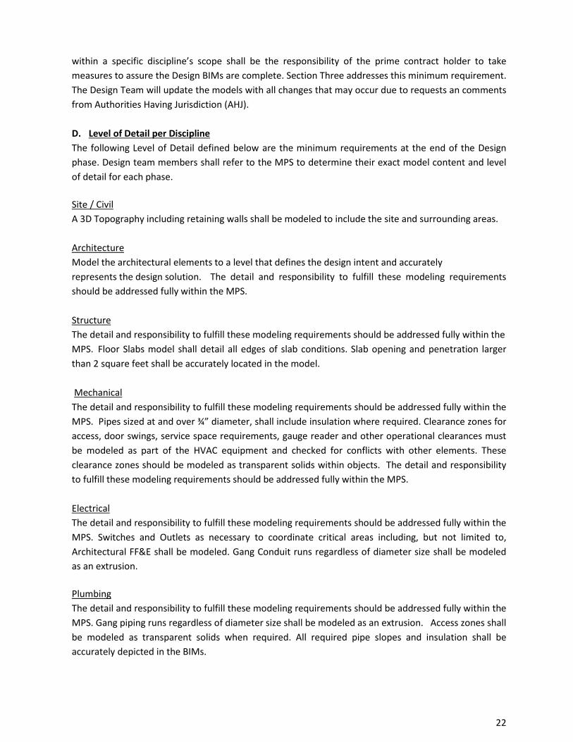
D. Level of Detail per Discipline The following Level of Detail defined below are the minimum requirements at the end of the Design phase. Design team members shall refer to the MPS to determine their exact model content and level of detail for each phase.
Site / Civil A 3D Topography including retaining walls shall be modeled to include the site and surrounding areas. Architecture Model the architectural elements to a level that defines the design intent and accurately represents the design solution. The detail and responsibility to fulfill these modeling requirements should be addressed fully within the MPS. Structure The detail and responsibility to fulfill these modeling requirements should be addressed fully within the MPS. Floor Slabs model shall detail all edges of slab conditions. Slab opening and penetration larger than 2 square feet shall be accurately located in the model. Mechanical The detail and responsibility to fulfill these modeling requirements should be addressed fully within the MPS. Pipes sized at and over ¾” diameter, shall include insulation where required. Clearance zones for access, door swings, service space requirements, gauge reader and other operational clearances must be modeled as part of the HVAC equipment and checked for conflicts with other elements. These clearance zones should be modeled as transparent solids within objects. The detail and responsibility to fulfill these modeling requirements should be addressed fully within the MPS. Electrical The detail and responsibility to fulfill these modeling requirements should be addressed fully within the MPS. Switches and Outlets as necessary to coordinate critical areas including, but not limited to, Architectural FF&E shall be modeled. Gang Conduit runs regardless of diameter size shall be modeled as an extrusion.
Plumbing The detail and responsibility to fulfill these modeling requirements should be addressed fully within the MPS. Gang piping runs regardless of diameter size shall be modeled as an extrusion. Access zones shall be modeled as transparent solids when required. All required pipe slopes and insulation shall be accurately depicted in the BIMs.
No portion of this work may be reproduced without the express written permission of the copyright holders. All rights reserved Broward County Aviation Department
22
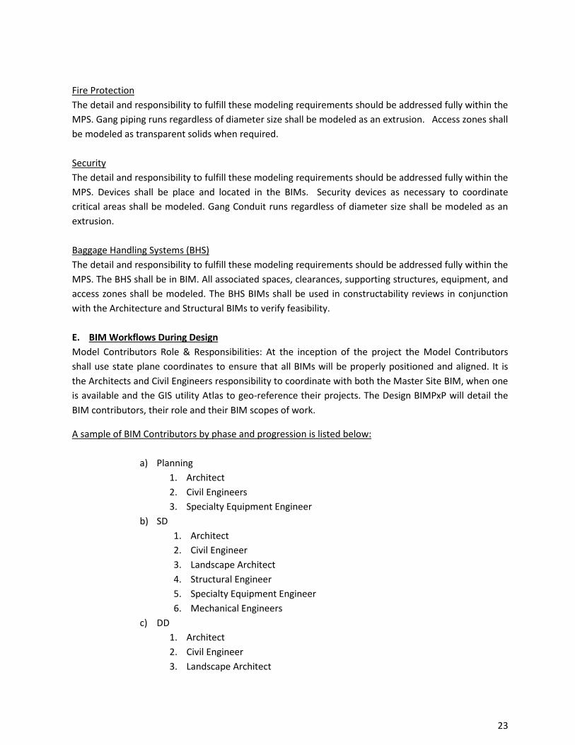
Fire Protection The detail and responsibility to fulfill these modeling requirements should be addressed fully within the MPS. Gang piping runs regardless of diameter size shall be modeled as an extrusion. Access zones shall be modeled as transparent solids when required. Security The detail and responsibility to fulfill these modeling requirements should be addressed fully within the MPS. Devices shall be place and located in the BIMs. Security devices as necessary to coordinate critical areas shall be modeled. Gang Conduit runs regardless of diameter size shall be modeled as an extrusion. Baggage Handling Systems (BHS) The detail and responsibility to fulfill these modeling requirements should be addressed fully within the MPS. The BHS shall be in BIM. All associated spaces, clearances, supporting structures, equipment, and access zones shall be modeled. The BHS BIMs shall be used in constructability reviews in conjunction with the Architecture and Structural BIMs to verify feasibility. E. BIM Workflows During Design Model Contributors Role & Responsibilities: At the inception of the project the Model Contributors shall use state plane coordinates to ensure that all BIMs will be properly positioned and aligned. It is the Architects and Civil Engineers responsibility to coordinate with both the Master Site BIM, when one is available and the GIS utility Atlas to geo-reference their projects. The Design BIMPxP will detail the BIM contributors, their role and their BIM scopes of work.
A sample of BIM Contributors by phase and progression is listed below:
a) Planning 1. Architect 2. Civil Engineers 3. Specialty Equipment Engineer
b) SD 1. Architect 2. Civil Engineer 3. Landscape Architect 4. Structural Engineer 5. Specialty Equipment Engineer 6. Mechanical Engineers
c) DD 1. Architect 2. Civil Engineer 3. Landscape Architect
No portion of this work may be reproduced without the express written permission of the copyright holders. All rights reserved Broward County Aviation Department
23

4. Structural Engineer 5. Specialty Equipment Engineer 6. MEPF Engineers 7. Security & IT Engineers
d) CD 1. Architect 2. Civil Engineer 3. Structural Engineer 4. Specialty Equipment Engineer 5. MEPF Engineers 6. Security & IT Engineers 7. Owner Supplied Vendor and Equipment
Each discipline shall identify a single point of contact as Model Manager for their contribution. The Model Manager shall be responsible for any and all the content found inside their models. The Federated BIMs shall not carry redundant content belonging to another discipline. Proper care shall be taken by each Model Contributor to reference other BIMs as linked files inside their BIMs in order to create their deliverables. Any exceptions to this rule shall be clearly defined in the Design BIMPxP and is subject to BCAD approval.
F. BIM Collaboration and Model Sharing During Design BIM Collaboration: The Design Team shall establish regular meetings to assure constructability of the Federated Design BIM at least once during the SD, DD and CD Phases. The Design team is expected to invite BCAD and others BCAD deems necessary. These meetings can be held online.
The Design Team is responsible for the regular upload of Design Submittals to BCAD’s Document Control System. BCADs Project folder structure and naming conventions will be made available to the Design BIM Team prior to the time of writing the Design BIMPxP. Model Sharing: The Design Team is expected to follow BCAD’s model sharing standards for information exchange with Owner and must also have their own protocols for exchanging working BIMs among the Design Team members. These protocols shall be specifically and clearly addressed in the Design BIMPxP in terms of what sharing method will be used, i.e. web-based exchange servers or FTP’s and their folder structure.
Fully Coordinated Design Intent BIM does not mean Clash Free but rather that the Design Team will design, to the best of their ability, building systems which will fit and are constructible as intended. The Design Team shall demonstrate that any clashes that exist in their Design Intent Federated BIM can be addressed in the Construction BIMs through means and methods.
G. Design Deliverables 2D Contract Documents: At the end of Design the Design Team shall submit a set of Construction Documents which will include a Specification Manual. The requirements for delivering the 2D contract
No portion of this work may be reproduced without the express written permission of the copyright holders. All rights reserved Broward County Aviation Department
24

document set representing the design efforts at each phase of design does not change. The Design Team shall refer to BCAD’s Standard contract deliverables for the project and meet them at a minimum.
Design BIMPxP: The Design BIMPxP is due prior to the start of Design and 30 days after authorization to proceed. Design BIMs: Design BIMs are expected as deliverables at the end of each design phase in their native file formats and in IFC (2x3). These deliverables shall meet the minimum BIM Content Requirements defined in this Standard and the BIMPxP / MPS. Federated Design BIM: A Federated Design BIM is expected as deliverable at the end of each design phase in an approved format. (See Section Five). All associated and linked data shall be organized in the BCAD’s Document Control System and all links shall be maintained in the Federated BIM. COBie Deliverable During Design:
The first COBie deliverable is provided using the 100% Design BIMs. The second COBie deliverable will
be after product approval by the design team from the construction submittals. Refer to Section Ten.
No portion of this work may be reproduced without the express written permission of the copyright holders. All rights reserved Broward County Aviation Department
25
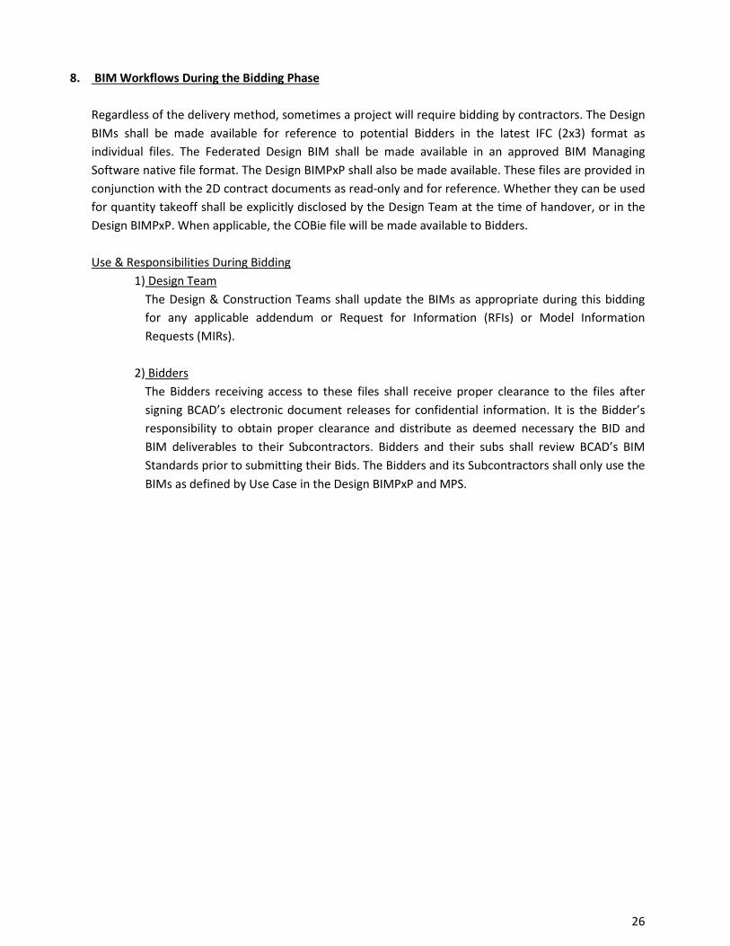
8. BIM Workflows During the Bidding Phase Regardless of the delivery method, sometimes a project will require bidding by contractors. The Design BIMs shall be made available for reference to potential Bidders in the latest IFC (2x3) format as individual files. The Federated Design BIM shall be made available in an approved BIM Managing Software native file format. The Design BIMPxP shall also be made available. These files are provided in conjunction with the 2D contract documents as read-only and for reference. Whether they can be used for quantity takeoff shall be explicitly disclosed by the Design Team at the time of handover, or in the Design BIMPxP. When applicable, the COBie file will be made available to Bidders. Use & Responsibilities During Bidding
1) Design Team The Design & Construction Teams shall update the BIMs as appropriate during this bidding for any applicable addendum or Request for Information (RFIs) or Model Information Requests (MIRs).
2) Bidders The Bidders receiving access to these files shall receive proper clearance to the files after signing BCAD’s electronic document releases for confidential information. It is the Bidder’s responsibility to obtain proper clearance and distribute as deemed necessary the BID and BIM deliverables to their Subcontractors. Bidders and their subs shall review BCAD’s BIM Standards prior to submitting their Bids. The Bidders and its Subcontractors shall only use the BIMs as defined by Use Case in the Design BIMPxP and MPS.
No portion of this work may be reproduced without the express written permission of the copyright holders. All rights reserved Broward County Aviation Department
26
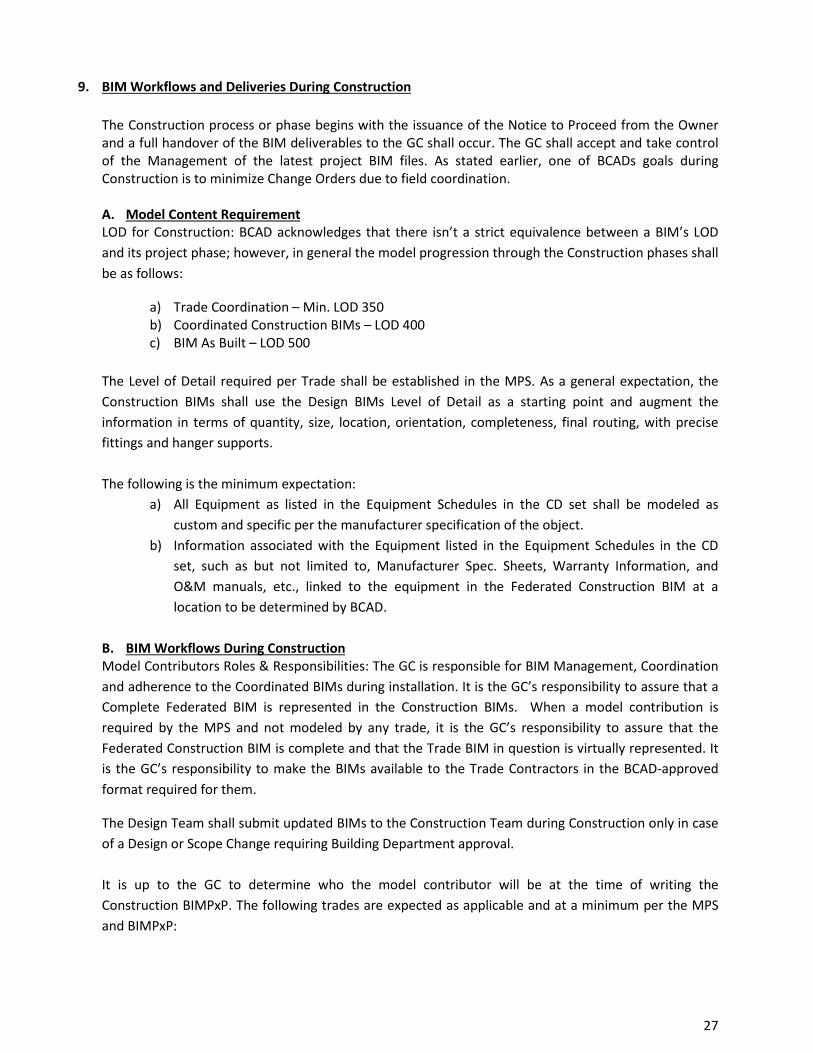
9. BIM Workflows and Deliveries During Construction
The Construction process or phase begins with the issuance of the Notice to Proceed from the Owner and a full handover of the BIM deliverables to the GC shall occur. The GC shall accept and take control of the Management of the latest project BIM files. As stated earlier, one of BCADs goals during Construction is to minimize Change Orders due to field coordination. A. Model Content Requirement LOD for Construction: BCAD acknowledges that there isn’t a strict equivalence between a BIM’s LOD and its project phase; however, in general the model progression through the Construction phases shall be as follows:
a) Trade Coordination – Min. LOD 350 b) Coordinated Construction BIMs – LOD 400 c) BIM As Built – LOD 500
The Level of Detail required per Trade shall be established in the MPS. As a general expectation, the Construction BIMs shall use the Design BIMs Level of Detail as a starting point and augment the information in terms of quantity, size, location, orientation, completeness, final routing, with precise fittings and hanger supports.
The following is the minimum expectation:
a) All Equipment as listed in the Equipment Schedules in the CD set shall be modeled as custom and specific per the manufacturer specification of the object.
b) Information associated with the Equipment listed in the Equipment Schedules in the CD set, such as but not limited to, Manufacturer Spec. Sheets, Warranty Information, and O&M manuals, etc., linked to the equipment in the Federated Construction BIM at a location to be determined by BCAD.
B. BIM Workflows During Construction Model Contributors Roles & Responsibilities: The GC is responsible for BIM Management, Coordination and adherence to the Coordinated BIMs during installation. It is the GC’s responsibility to assure that a Complete Federated BIM is represented in the Construction BIMs. When a model contribution is required by the MPS and not modeled by any trade, it is the GC’s responsibility to assure that the Federated Construction BIM is complete and that the Trade BIM in question is virtually represented. It is the GC’s responsibility to make the BIMs available to the Trade Contractors in the BCAD-approved format required for them.
The Design Team shall submit updated BIMs to the Construction Team during Construction only in case of a Design or Scope Change requiring Building Department approval. It is up to the GC to determine who the model contributor will be at the time of writing the Construction BIMPxP. The following trades are expected as applicable and at a minimum per the MPS and BIMPxP:
No portion of this work may be reproduced without the express written permission of the copyright holders. All rights reserved Broward County Aviation Department
27
1. Utilities 2. Site works 3. Shell & Core 4. Exterior Glazing & Curtain walls 5. Structural Steel 6. Interior Walls, Ceilings, Doors & Windows 7. Specialty Components through Owner Contracted Vendors 8. HVAC 9. Electrical including High and Low voltage 10. Plumbing 11. Fire Protection 12. Security and Building Automated Systems (BAS)
BIM Collaboration During Construction: The GC is expected to know how to run BIM Coordination and is expected to delineate his/her protocols and quality controls in the Construction BIMPxP. It is up to the Construction Team to hold a Construction BIM Kickoff Meeting where the MPS and BIMPxP will be reviewed. The GC team is expected to invite BCAD and the Design Team during scheduled Trade coordination. These meetings can be held online or otherwise and BCAD and the Design Team are expected to attend.
The Construction Team is responsible for the regular upload of Construction Submittals to BCAD. These uploads are expected monthly. BCADs Project folder structure and naming conventions will be made available to the Design & Construction Team at the time of writing the BIMPxP. Model Sharing During Construction: The Construction Team is expected to have its own protocols for exchanging working BIMs amongst team members. These protocols shall be specifically and clearly addressed in the Construction BIMPxP in terms of what sharing method will be used, i.e. web-based exchange servers or FTP’s and their folder structure.
Model sharing and BIM collaboration is critical to assure a Clash Free Construction BIM before installation. Clash Detection and Spatial Coordination: At a minimum, Clash detection between any, and all of the following elements, should occur:
a. Architecture b. Structure c. Mechanical d. Fire e. Electrical f. Plumbing g. Life Safety h. Equipment
No portion of this work may be reproduced without the express written permission of the copyright holders. All rights reserved Broward County Aviation Department
28
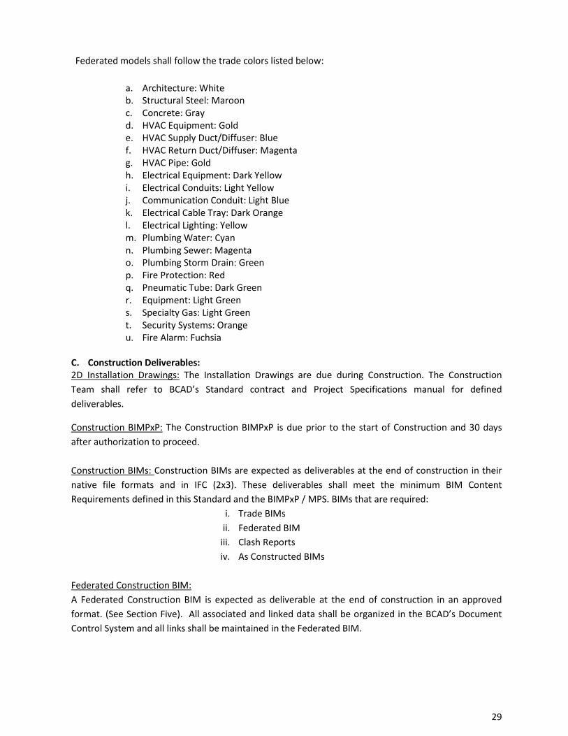
Federated models shall follow the trade colors listed below:
a. Architecture: White b. Structural Steel: Maroon c. Concrete: Gray d. HVAC Equipment: Gold e. HVAC Supply Duct/Diffuser: Blue f. HVAC Return Duct/Diffuser: Magenta g. HVAC Pipe: Gold h. Electrical Equipment: Dark Yellow i. Electrical Conduits: Light Yellow j. Communication Conduit: Light Blue k. Electrical Cable Tray: Dark Orange l. Electrical Lighting: Yellow m. Plumbing Water: Cyan n. Plumbing Sewer: Magenta o. Plumbing Storm Drain: Green p. Fire Protection: Red q. Pneumatic Tube: Dark Green r. Equipment: Light Green s. Specialty Gas: Light Green t. Security Systems: Orange u. Fire Alarm: Fuchsia
C. Construction Deliverables: 2D Installation Drawings: The Installation Drawings are due during Construction. The Construction Team shall refer to BCAD’s Standard contract and Project Specifications manual for defined deliverables.
Construction BIMPxP: The Construction BIMPxP is due prior to the start of Construction and 30 days after authorization to proceed. Construction BIMs: Construction BIMs are expected as deliverables at the end of construction in their native file formats and in IFC (2x3). These deliverables shall meet the minimum BIM Content Requirements defined in this Standard and the BIMPxP / MPS. BIMs that are required:
i. Trade BIMs ii. Federated BIM
iii. Clash Reports iv. As Constructed BIMs
Federated Construction BIM: A Federated Construction BIM is expected as deliverable at the end of construction in an approved format. (See Section Five). All associated and linked data shall be organized in the BCAD’s Document Control System and all links shall be maintained in the Federated BIM.
No portion of this work may be reproduced without the express written permission of the copyright holders. All rights reserved Broward County Aviation Department
29

COBie Deliverable During Construction:
The COBie deliverables are defined in the Design Teams BIMPxP and the Construction BIMPxP. Best
Practices and workflow are detailed in Section Ten.
No portion of this work may be reproduced without the express written permission of the copyright holders. All rights reserved Broward County Aviation Department
30
10. Construction Operations Building Information Exchange (COBie) Workflow, Roles and Responsibilities and Deliverables
Construction Operations Building information exchange (COBie) was created to standardize the exchange of information between construction and Facilities Mangers at handover in a consistent format. Standardizing information exchanges eliminates the need for repeated or custom mapping. Once a standard is adopted, the software vendors can incorporate the Standard into their applications and users do not have to worry about connecting databases as they can be pre-mapped.
Although the COBie deliverable format has been in practice for several years, it had not been incorporated into software development plans as it was not considered a “standard”. In 2011, COBie Standard was adopted into the National Building Information Modeling Standard- United States, Version 2 (NBIMS-US v2). Now as a recognized standard, COBie has been implemented by BIM authoring tool software vendors as well CMMS providers. For a complete list of COBie capable software can be found on the buildingSMARTalliance website at http://www.nibs.org/?page=bsa_cobiemm
Information on how to use COBie may be found at http://www.wbdg.org/resources/cobie.p
This section is intended to:
Describe the List of Assets requiring COBie Data Set Define the Roles and Responsibilities of Design & Construction Team members
for COBie deliverables Identify both the COBie and BCAD specified data sets (attributes) to meet the
required deliverable, Recommend best practices Discuss data validation processes for quality control Provide a COBie Deliverable Progression Schedule
A. List of Assets requiring COBie Data Set At a minimum and not limited to, BCAD will require COBie data sets for all components on the Equipment List per the Construction Documents that require any of the following:
Scheduled preventative maintenance i.e. Mechanical, Electrical, Routine maintenance/inspections : i.e. Plumbing Regulatory inspections i.e. life safety related: fire extinguisher, fire dampers,
backflow preventers B. Roles & Responsibilities All COBie deliverables will be provided in the COBie Standard file format conforming to version 2, release 4, (COBie2 2.40). A sample COBie deliverable format file containing BCAD additional data sets may be provided upon request from BCAD.
The chart below identifies the minimum COBie data set required BCAD. The first available collection point of each attribute has been identify as either at 100% Design (D100), after Contractor approved submittals (CSA), or after Contractor installations (CI). The responsible party for providing and collecting the COBie data
No portion of this work may be reproduced without the express written permission of the copyright holders. All rights reserved Broward County Aviation Department
31
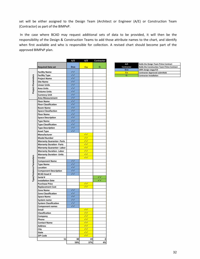
set will be either assigned to the Design Team (Architect or Engineer (A/E) or Construction Team (Contractor) as part of the BIMPxP.
In the case where BCAD may request additional sets of data to be provided, it will then be the responsibility of the Design & Construction Teams to add those attribute names to the chart, and identify when first available and who is responsible for collection. A revised chart should become part of the approved BIMPxP plan.
A/E Holds the Design Team Prime Contract Contractor Holds the Construction Team Prime Contract
D100 100% design stage/CDCSA Contractor Approved submittalsCI Contractor Installation
No portion of this work may be reproduced without the express written permission of the copyright holders. All rights reserved Broward County Aviation Department
32
A/E A/E Contractor
Required Data set D100 CI
Facility Name Facility Type Project Name Site Name Linear Units
Area Units Volume Units Currency Unit Area Measurement
Floor Name Floor Classification
Room Name Space Classifaction
Floor Name Space Description
Type Name
Type Classification
Type Description
Asset Type
Manufacturer
Model Number Warranty Guarantor- Parts Warranty Duration- Parts Warranty Guarantor- Labor
Warranty Duration- Labor
Warranty Duration- Units Vendor
Component Name Type Name Location Component Description BCAD Asset # Serial # Installation Date Purchase Price Replacement Cost
Zone Name Zone Classification Space Name
System name System Classification Component names
Email Classification Company Phone Contact Name Address City State ZIP Code
51 30 19 259% 37% 4%
CSA
Proj
ect P
aram
eter
sTy
pe/I
nsta
nce
Para
met
ers
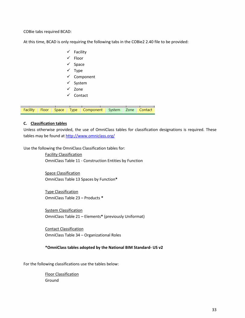
COBie tabs required BCAD:
At this time, BCAD is only requiring the following tabs in the COBie2 2.40 file to be provided:
Facility Floor Space Type Component System Zone Contact
C. Classification tables Unless otherwise provided, the use of OmniClass tables for classification designations is required. These tables may be found at http://www.omniclass.org/ Use the following the OmniClass Classification tables for:
Facility Classification OmniClass Table 11 - Construction Entities by Function Space Classification OmniClass Table 13 Spaces by Function* Type Classification OmniClass Table 23 – Products * System Classification OmniClass Table 21 – Elements* (previously Uniformat) Contact Classification
OmniClass Table 34 – Organizational Roles
*OmniClass tables adopted by the National BIM Standard- US v2
For the following classifications use the tables below:
Floor Classification Ground
No portion of this work may be reproduced without the express written permission of the copyright holders. All rights reserved Broward County Aviation Department
33
Level Roof Zone Classification Circulation Zone Lighting Zone Fire Alarm Zone Occupancy Zone Ventilation Zone System Classification
As determined by BCAD
D. COBie Standard and BCAD specified data set The chart below is the information that you are required to have and is intended to clarify where the data should reside in a COBie formatted file deliverable (spreadsheet).
No portion of this work may be reproduced without the express written permission of the copyright holders. All rights reserved Broward County Aviation Department
34
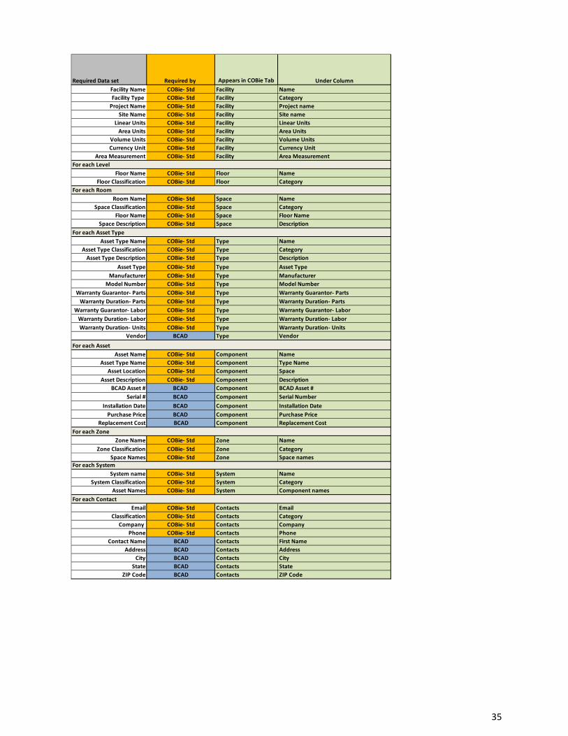
Required Data set Required by Appears in COBie Tab Under ColumnFacility Name COBie- Std Facility NameFacility Type COBie- Std Facility Category
Project Name COBie- Std Facility Project nameSite Name COBie- Std Facility Site name
Linear Units COBie- Std Facility Linear UnitsArea Units COBie- Std Facility Area Units
Volume Units COBie- Std Facility Volume UnitsCurrency Unit COBie- Std Facility Currency Unit
Area Measurement COBie- Std Facility Area Measurement
Floor Name COBie- Std Floor NameFloor Classification COBie- Std Floor Category
Room Name COBie- Std Space NameSpace Classification COBie- Std Space Category
Floor Name COBie- Std Space Floor NameSpace Description COBie- Std Space Description
Asset Type Name COBie- Std Type NameAsset Type Classification COBie- Std Type Category
Asset Type Description COBie- Std Type DescriptionAsset Type COBie- Std Type Asset Type
Manufacturer COBie- Std Type ManufacturerModel Number COBie- Std Type Model Number
Warranty Guarantor- Parts COBie- Std Type Warranty Guarantor- PartsWarranty Duration- Parts COBie- Std Type Warranty Duration- Parts
Warranty Guarantor- Labor COBie- Std Type Warranty Guarantor- LaborWarranty Duration- Labor COBie- Std Type Warranty Duration- LaborWarranty Duration- Units COBie- Std Type Warranty Duration- Units
Vendor BCAD Type Vendor
Asset Name COBie- Std Component NameAsset Type Name COBie- Std Component Type Name
Asset Location COBie- Std Component SpaceAsset Description COBie- Std Component Description
BCAD Asset # BCAD Component BCAD Asset #Serial # BCAD Component Serial Number
Installation Date BCAD Component Installation DatePurchase Price BCAD Component Purchase Price
Replacement Cost BCAD Component Replacement Cost
Zone Name COBie- Std Zone NameZone Classification COBie- Std Zone Category
Space Names COBie- Std Zone Space names
System name COBie- Std System NameSystem Classification COBie- Std System Category
Asset Names COBie- Std System Component names
Email COBie- Std Contacts EmailClassification COBie- Std Contacts Category
Company COBie- Std Contacts Company Phone COBie- Std Contacts Phone
Contact Name BCAD Contacts First NameAddress BCAD Contacts Address
City BCAD Contacts CityState BCAD Contacts State
ZIP Code BCAD Contacts ZIP Code
For each Level
For each Contact
For each System
For each Zone
For each Asset
For each Asset Type
For each Room
No portion of this work may be reproduced without the express written permission of the copyright holders. All rights reserved Broward County Aviation Department
35
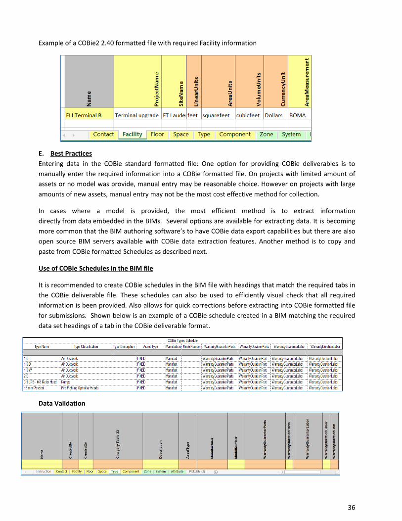
Example of a COBie2 2.40 formatted file with required Facility information
E. Best Practices Entering data in the COBie standard formatted file: One option for providing COBie deliverables is to manually enter the required information into a COBie formatted file. On projects with limited amount of assets or no model was provide, manual entry may be reasonable choice. However on projects with large amounts of new assets, manual entry may not be the most cost effective method for collection.
In cases where a model is provided, the most efficient method is to extract information directly from data embedded in the BIMs. Several options are available for extracting data. It is becoming more common that the BIM authoring software’s to have COBie data export capabilities but there are also open source BIM servers available with COBie data extraction features. Another method is to copy and paste from COBie formatted Schedules as described next.
Use of COBie Schedules in the BIM file
It is recommended to create COBie schedules in the BIM file with headings that match the required tabs in the COBie deliverable file. These schedules can also be used to efficiently visual check that all required information is been provided. Also allows for quick corrections before extracting into COBie formatted file for submissions. Shown below is an example of a COBie schedule created in a BIM matching the required data set headings of a tab in the COBie deliverable format.
Data Validation
No portion of this work may be reproduced without the express written permission of the copyright holders. All rights reserved Broward County Aviation Department
36
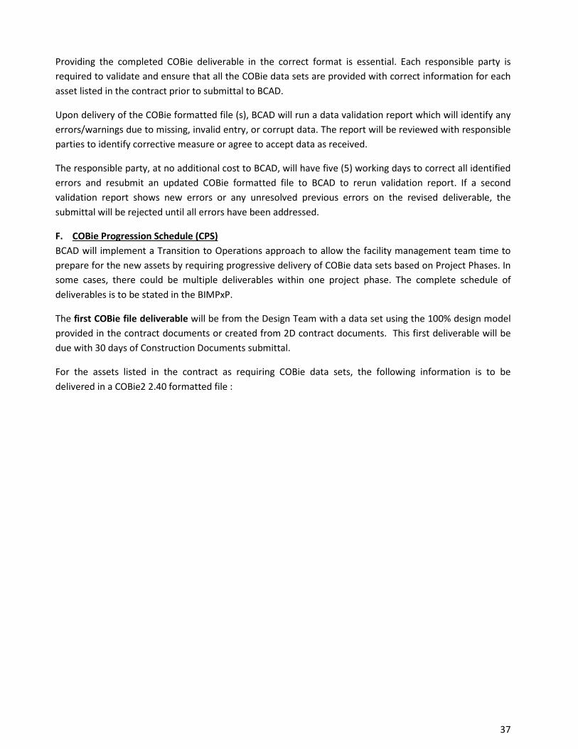
Providing the completed COBie deliverable in the correct format is essential. Each responsible party is required to validate and ensure that all the COBie data sets are provided with correct information for each asset listed in the contract prior to submittal to BCAD.
Upon delivery of the COBie formatted file (s), BCAD will run a data validation report which will identify any errors/warnings due to missing, invalid entry, or corrupt data. The report will be reviewed with responsible parties to identify corrective measure or agree to accept data as received.
The responsible party, at no additional cost to BCAD, will have five (5) working days to correct all identified errors and resubmit an updated COBie formatted file to BCAD to rerun validation report. If a second validation report shows new errors or any unresolved previous errors on the revised deliverable, the submittal will be rejected until all errors have been addressed.
F. COBie Progression Schedule (CPS) BCAD will implement a Transition to Operations approach to allow the facility management team time to prepare for the new assets by requiring progressive delivery of COBie data sets based on Project Phases. In some cases, there could be multiple deliverables within one project phase. The complete schedule of deliverables is to be stated in the BIMPxP.
The first COBie file deliverable will be from the Design Team with a data set using the 100% design model provided in the contract documents or created from 2D contract documents. This first deliverable will be due with 30 days of Construction Documents submittal.
For the assets listed in the contract as requiring COBie data sets, the following information is to be delivered in a COBie2 2.40 formatted file :
No portion of this work may be reproduced without the express written permission of the copyright holders. All rights reserved Broward County Aviation Department
37
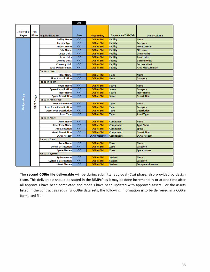
The second COBie file deliverable will be during submittal approval (Csa) phase, also provided by design team. This deliverable should be stated in the BIMPxP as it may be done incrementally or at one time after all approvals have been completed and models have been updated with approved assets. For the assets listed in the contract as requiring COBie data sets, the following information is to be delivered in a COBie formatted file:
No portion of this work may be reproduced without the express written permission of the copyright holders. All rights reserved Broward County Aviation Department
38
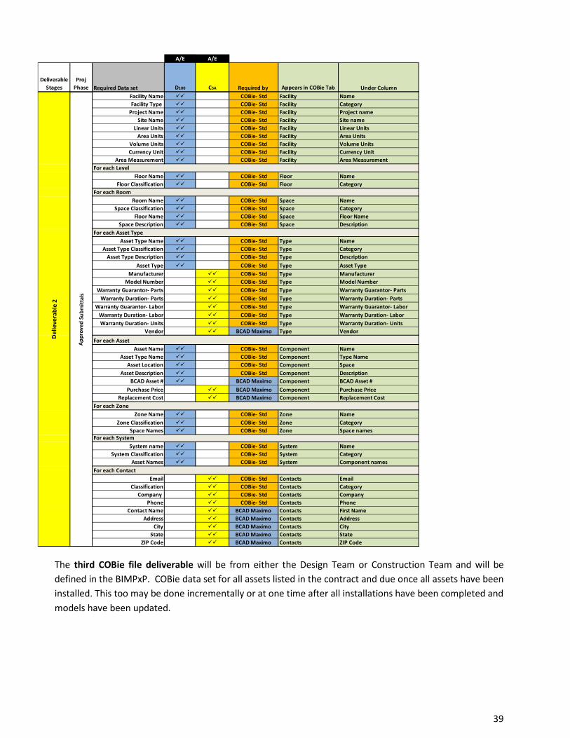
The third COBie file deliverable will be from either the Design Team or Construction Team and will be defined in the BIMPxP. COBie data set for all assets listed in the contract and due once all assets have been installed. This too may be done incrementally or at one time after all installations have been completed and models have been updated.
A/E A/E
Deliverable Stages
Proj Phase Required Data set D100 CSA Required by Appears in COBie Tab Under Column
Facility Name COBie- Std Facility NameFacility Type COBie- Std Facility Category
Project Name COBie- Std Facility Project nameSite Name COBie- Std Facility Site name
Linear Units COBie- Std Facility Linear UnitsArea Units COBie- Std Facility Area Units
Volume Units COBie- Std Facility Volume UnitsCurrency Unit COBie- Std Facility Currency Unit
Area Measurement COBie- Std Facility Area Measurement
Floor Name COBie- Std Floor NameFloor Classification COBie- Std Floor Category
Room Name COBie- Std Space NameSpace Classification COBie- Std Space Category
Floor Name COBie- Std Space Floor NameSpace Description COBie- Std Space Description
Asset Type Name COBie- Std Type NameAsset Type Classification COBie- Std Type Category
Asset Type Description COBie- Std Type DescriptionAsset Type COBie- Std Type Asset Type
Manufacturer COBie- Std Type ManufacturerModel Number COBie- Std Type Model Number
Warranty Guarantor- Parts COBie- Std Type Warranty Guarantor- PartsWarranty Duration- Parts COBie- Std Type Warranty Duration- Parts
Warranty Guarantor- Labor COBie- Std Type Warranty Guarantor- LaborWarranty Duration- Labor COBie- Std Type Warranty Duration- LaborWarranty Duration- Units COBie- Std Type Warranty Duration- Units
Vendor BCAD Maximo Type Vendor
Asset Name COBie- Std Component NameAsset Type Name COBie- Std Component Type Name
Asset Location COBie- Std Component SpaceAsset Description COBie- Std Component Description
BCAD Asset # BCAD Maximo Component BCAD Asset #Purchase Price BCAD Maximo Component Purchase Price
Replacement Cost BCAD Maximo Component Replacement Cost
Zone Name COBie- Std Zone NameZone Classification COBie- Std Zone Category
Space Names COBie- Std Zone Space names
System name COBie- Std System NameSystem Classification COBie- Std System Category
Asset Names COBie- Std System Component names
Email COBie- Std Contacts EmailClassification COBie- Std Contacts Category
Company COBie- Std Contacts Company Phone COBie- Std Contacts Phone
Contact Name BCAD Maximo Contacts First NameAddress BCAD Maximo Contacts Address
City BCAD Maximo Contacts CityState BCAD Maximo Contacts State
ZIP Code BCAD Maximo Contacts ZIP Code
For each Level
For each Contact
For each System
For each Zone
For each Asset
For each Asset Type
For each Room
Del
ieve
rabl
e 2
Appr
oved
Sub
mitt
als
No portion of this work may be reproduced without the express written permission of the copyright holders. All rights reserved Broward County Aviation Department
39
The final COBie file deliverable will be from Design Team or Construction Team as defined in the BIMPxP that represents the As-Built models and will be a complete COBie data set for all assets listed in the contract, and due same time as As-Built models.
A/E A/E Contractor
Deliverable Stages
Proj Phase Required Data set D100 CSA CI Required by Appears in COBie Tab Under Column
Facility Name COBie- Std Facility NameFacility Type COBie- Std Facility Category
Project Name COBie- Std Facility Project nameSite Name COBie- Std Facility Site name
Linear Units COBie- Std Facility Linear UnitsArea Units COBie- Std Facility Area Units
Volume Units COBie- Std Facility Volume UnitsCurrency Unit COBie- Std Facility Currency Unit
Area Measurement COBie- Std Facility Area Measurement
Floor Name COBie- Std Floor NameFloor Classification COBie- Std Floor Category
Room Name COBie- Std Space NameSpace Classification COBie- Std Space Category
Floor Name COBie- Std Space Floor NameSpace Description COBie- Std Space Description
Asset Type Name COBie- Std Type NameAsset Type Classification COBie- Std Type Category
Asset Type Description COBie- Std Type DescriptionAsset Type COBie- Std Type Asset Type
Manufacturer COBie- Std Type ManufacturerModel Number COBie- Std Type Model Number
Warranty Guarantor- Parts COBie- Std Type Warranty Guarantor- PartsWarranty Duration- Parts COBie- Std Type Warranty Duration- Parts
Warranty Guarantor- Labor COBie- Std Type Warranty Guarantor- LaborWarranty Duration- Labor COBie- Std Type Warranty Duration- LaborWarranty Duration- Units COBie- Std Type Warranty Duration- Units
Vendor BCAD Maximo Type Vendor
Asset Name COBie- Std Component NameAsset Type Name COBie- Std Component Type Name
Asset Location COBie- Std Component SpaceAsset Description COBie- Std Component Description
BCAD Asset # BCAD Maximo Component BCAD Asset #Serial # BCAD Maximo Component Serial Number
Installation Date BCAD Maximo Component Installation DatePurchase Price BCAD Maximo Component Purchase Price
Replacement Cost BCAD Maximo Component Replacement Cost
Zone Name COBie- Std Zone NameZone Classification COBie- Std Zone Category
Space Names COBie- Std Zone Space names
System name COBie- Std System NameSystem Classification COBie- Std System Category
Asset Names COBie- Std System Component names
Email COBie- Std Contacts EmailClassification COBie- Std Contacts Category
Company COBie- Std Contacts Company Phone COBie- Std Contacts Phone
Contact Name BCAD Maximo Contacts First NameAddress BCAD Maximo Contacts Address
City BCAD Maximo Contacts CityState BCAD Maximo Contacts State
ZIP Code BCAD Maximo Contacts ZIP Code
For each Level
For each Contact
Del
ieve
rabl
e 3
Inst
alla
tion
For each System
For each Zone
For each Asset
For each Asset Type
For each Room
No portion of this work may be reproduced without the express written permission of the copyright holders. All rights reserved Broward County Aviation Department
40

A/E
Deliverable Stages
Proj Phase Required Data set As-Built Required by Appears in COBie Tab Under Column
Facility Name COBie- Std Facility NameFacility Type COBie- Std Facility Category
Project Name COBie- Std Facility Project nameSite Name COBie- Std Facility Site name
Linear Units COBie- Std Facility Linear UnitsArea Units COBie- Std Facility Area Units
Volume Units COBie- Std Facility Volume UnitsCurrency Unit COBie- Std Facility Currency Unit
Area Measurement COBie- Std Facility Area Measurement
Floor Name COBie- Std Floor NameFloor Classification COBie- Std Floor Category
Room Name COBie- Std Space NameSpace Classification COBie- Std Space Category
Floor Name COBie- Std Space Floor NameSpace Description COBie- Std Space Description
Asset Type Name COBie- Std Type NameAsset Type Classification COBie- Std Type Category
Asset Type Description COBie- Std Type DescriptionAsset Type COBie- Std Type Asset Type
Manufacturer COBie- Std Type ManufacturerModel Number COBie- Std Type Model Number
Warranty Guarantor- Parts COBie- Std Type Warranty Guarantor- PartsWarranty Duration- Parts COBie- Std Type Warranty Duration- Parts
Warranty Guarantor- Labor COBie- Std Type Warranty Guarantor- LaborWarranty Duration- Labor COBie- Std Type Warranty Duration- LaborWarranty Duration- Units COBie- Std Type Warranty Duration- Units
Vendor BCAD Maximo Type Vendor
Asset Name COBie- Std Component NameAsset Type Name COBie- Std Component Type Name
Asset Location COBie- Std Component SpaceAsset Description COBie- Std Component Description
BCAD Asset # BCAD Maximo Component BCAD Asset #Serial # BCAD Maximo Component Serial Number
Installation Date BCAD Maximo Component Installation DatePurchase Price BCAD Maximo Component Purchase Price
Replacement Cost BCAD Maximo Component Replacement Cost
Zone Name COBie- Std Zone NameZone Classification COBie- Std Zone Category
Space Names COBie- Std Zone Space names
System name COBie- Std System NameSystem Classification COBie- Std System Category
Asset Names COBie- Std System Component names
Email COBie- Std Contacts EmailClassification COBie- Std Contacts Category
Company COBie- Std Contacts Company Phone COBie- Std Contacts Phone
Contact Name BCAD Maximo Contacts First NameAddress BCAD Maximo Contacts Address
City BCAD Maximo Contacts CityState BCAD Maximo Contacts State
ZIP Code BCAD Maximo Contacts ZIP Code
For each Level
For each Contact
For each System
For each Zone
For each Asset
For each Asset Type
For each Asset Type
For each Room
FIN
AL D
eliv
erab
le
As B
uilt
No portion of this work may be reproduced without the express written permission of the copyright holders. All rights reserved Broward County Aviation Department
41

11. Appendix A – Sample BIMPxP
No portion of this work may be reproduced without the express written permission of the copyright holders. All rights reserved Broward County Aviation Department
42
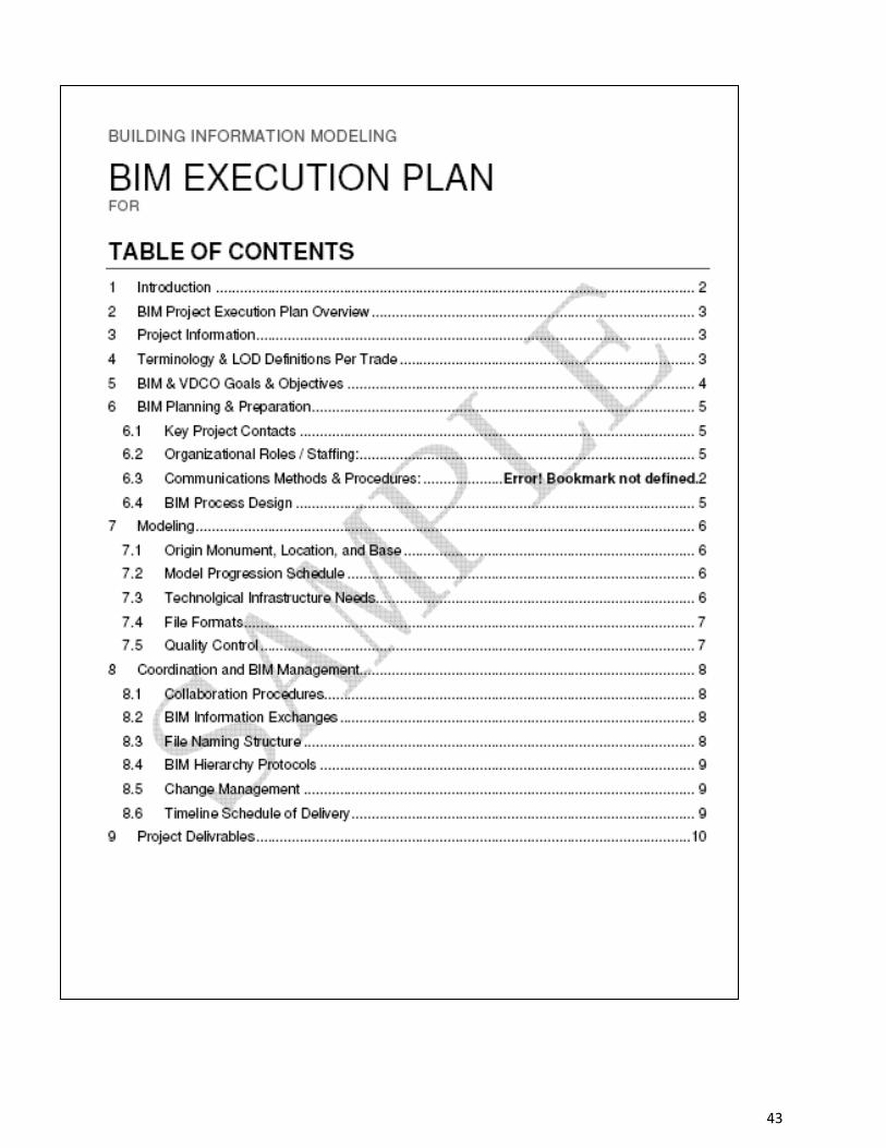
No portion of this work may be reproduced without the express written permission of the copyright holders. All rights reserved Broward County Aviation Department
43
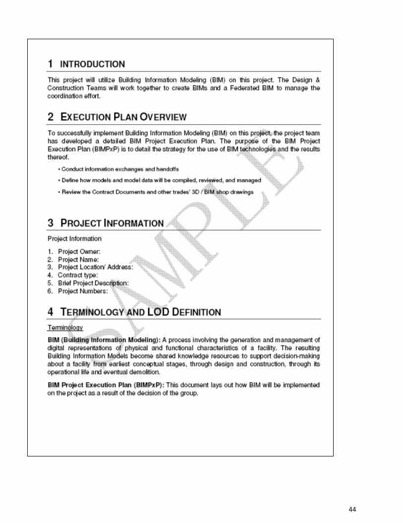
No portion of this work may be reproduced without the express written permission of the copyright holders. All rights reserved Broward County Aviation Department
44
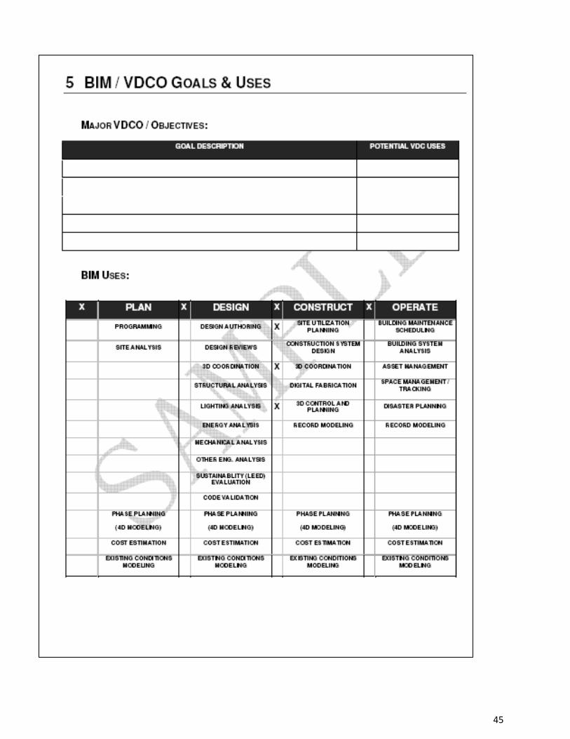
No portion of this work may be reproduced without the express written permission of the copyright holders. All rights reserved Broward County Aviation Department
45
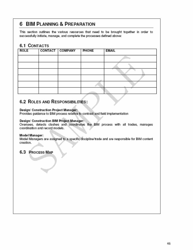
No portion of this work may be reproduced without the express written permission of the copyright holders. All rights reserved Broward County Aviation Department
46
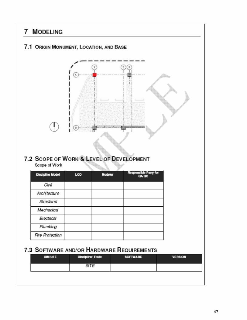
No portion of this work may be reproduced without the express written permission of the copyright holders. All rights reserved Broward County Aviation Department
47
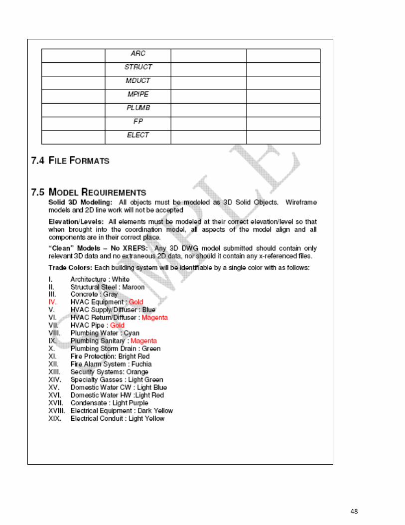
No portion of this work may be reproduced without the express written permission of the copyright holders. All rights reserved Broward County Aviation Department
48
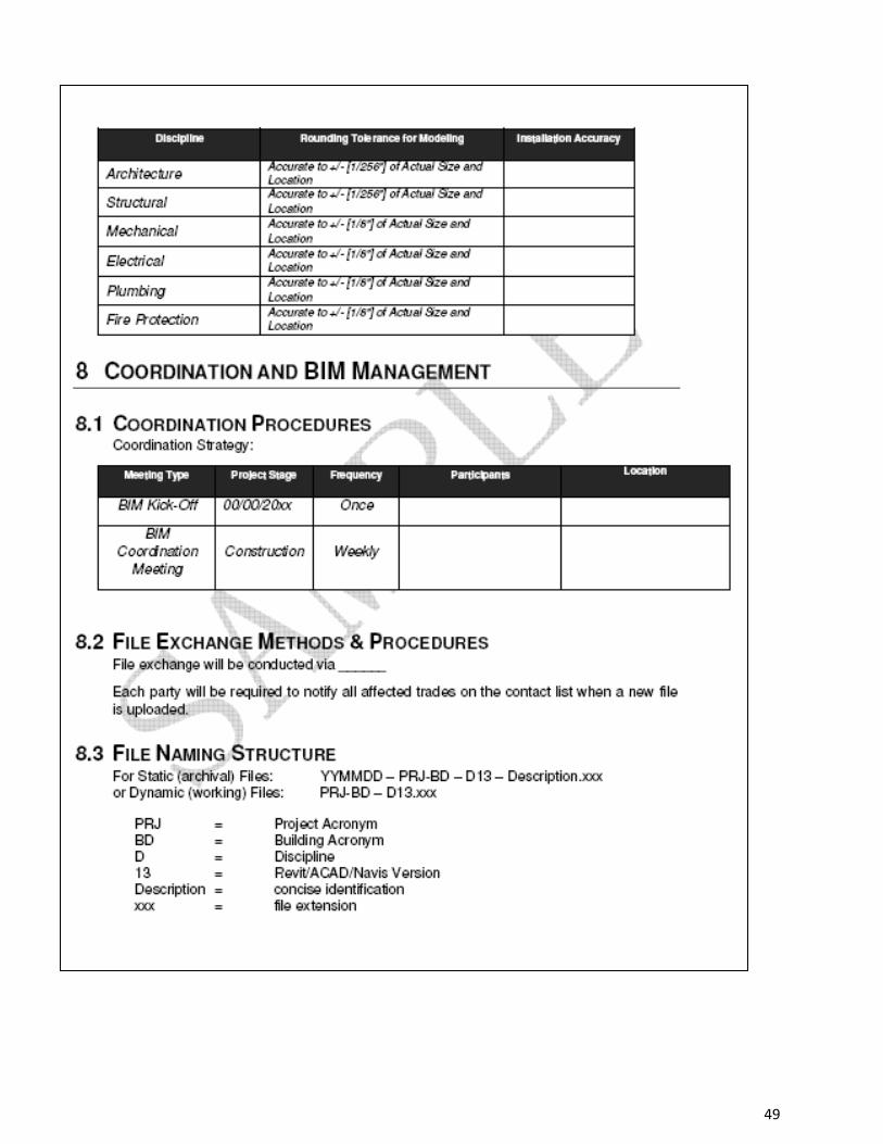
No portion of this work may be reproduced without the express written permission of the copyright holders. All rights reserved Broward County Aviation Department
49
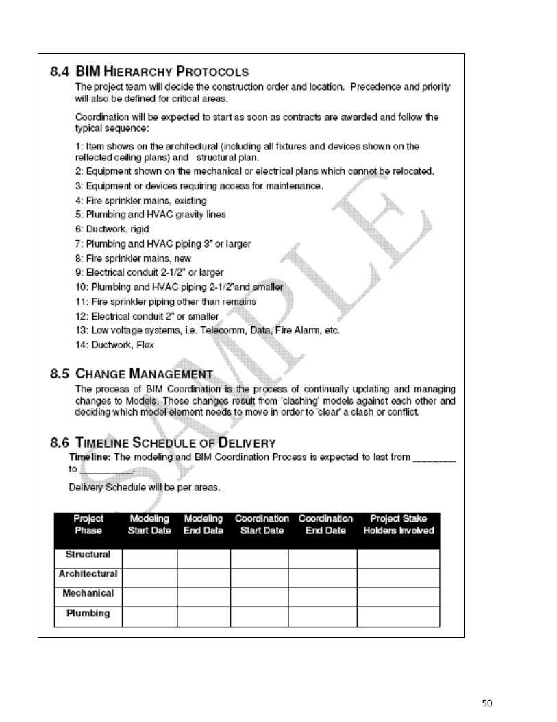
No portion of this work may be reproduced without the express written permission of the copyright holders. All rights reserved Broward County Aviation Department
50
No portion of this work may be reproduced without the express written permission of the copyright holders. All rights reserved Broward County Aviation Department
51
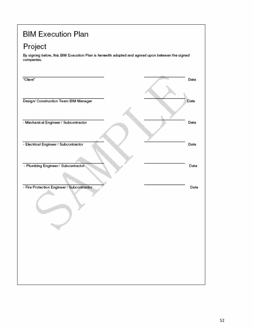
No portion of this work may be reproduced without the express written permission of the copyright holders. All rights reserved Broward County Aviation Department
52
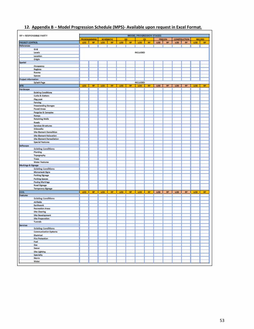
12. Appendix B – Model Progression Schedule (MPS)- Available upon request in Excel Format.
No portion of this work may be reproduced without the express written permission of the copyright holders. All rights reserved Broward County Aviation Department
53
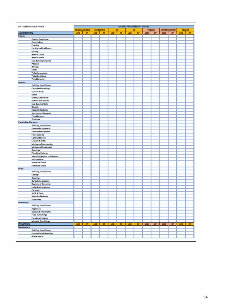
No portion of this work may be reproduced without the express written permission of the copyright holders. All rights reserved Broward County Aviation Department
54
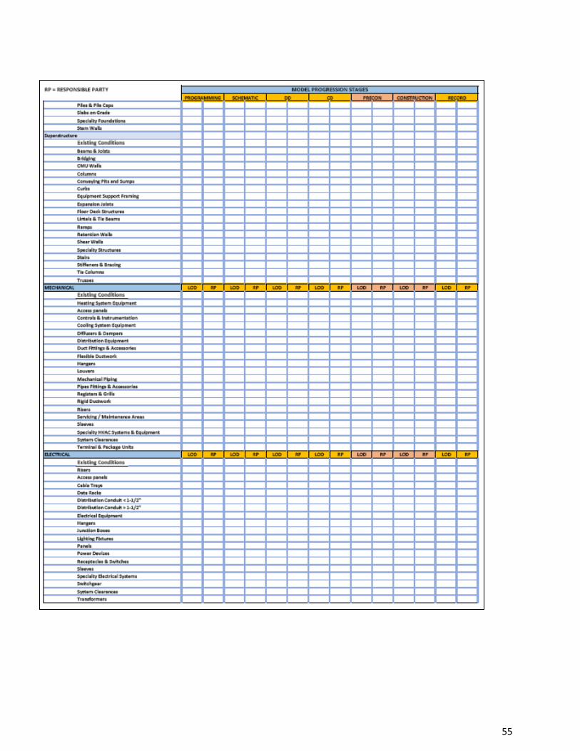
No portion of this work may be reproduced without the express written permission of the copyright holders. All rights reserved Broward County Aviation Department
55
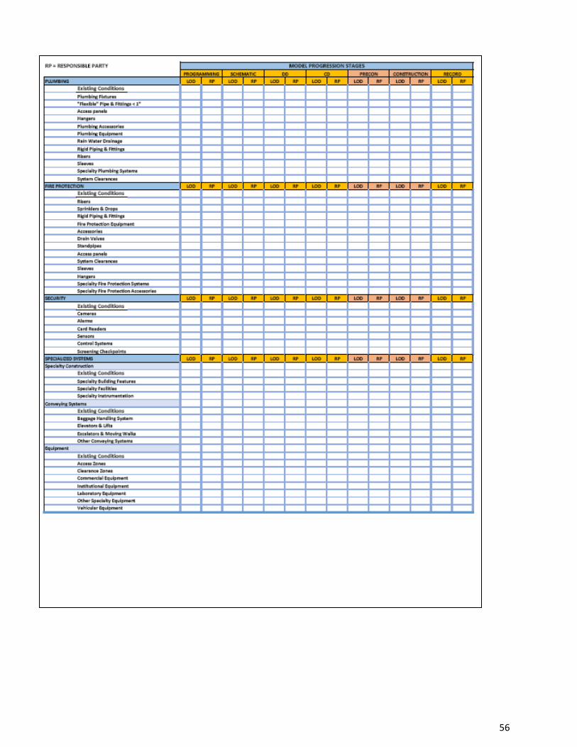
No portion of this work may be reproduced without the express written permission of the copyright holders. All rights reserved Broward County Aviation Department
56
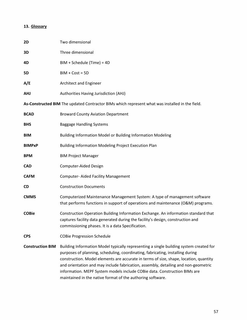
13. Glossary
2D Two dimensional
3D Three dimensional
4D BIM + Schedule (Time) = 4D
5D BIM + Cost = 5D
A/E Architect and Engineer
AHJ Authorities Having Jurisdiction (AHJ)
As-Constructed BIM The updated Contractor BIMs which represent what was installed in the field.
BCAD Broward County Aviation Department
BHS Baggage Handling Systems
BIM Building Information Model or Building Information Modeling
BIMPxP Building Information Modeling Project Execution Plan
BPM BIM Project Manager
CAD Computer-Aided Design
CAFM Computer- Aided Facility Management
CD Construction Documents
CMMS Computerized Maintenance Management System: A type of management software that performs functions in support of operations and maintenance (O&M) programs.
COBie Construction Operation Building Information Exchange. An information standard that captures facility data generated during the facility’s design, construction and commissioning phases. It is a data Specification.
CPS COBie Progression Schedule
Construction BIM Building Information Model typically representing a single building system created for purposes of planning, scheduling, coordinating, fabricating, installing during construction. Model elements are accurate in terms of size, shape, location, quantity and orientation and may include fabrication, assembly, detailing and non-geometric information. MEPF System models include COBie data. Construction BIMs are maintained in the native format of the authoring software.
No portion of this work may be reproduced without the express written permission of the copyright holders. All rights reserved Broward County Aviation Department
57
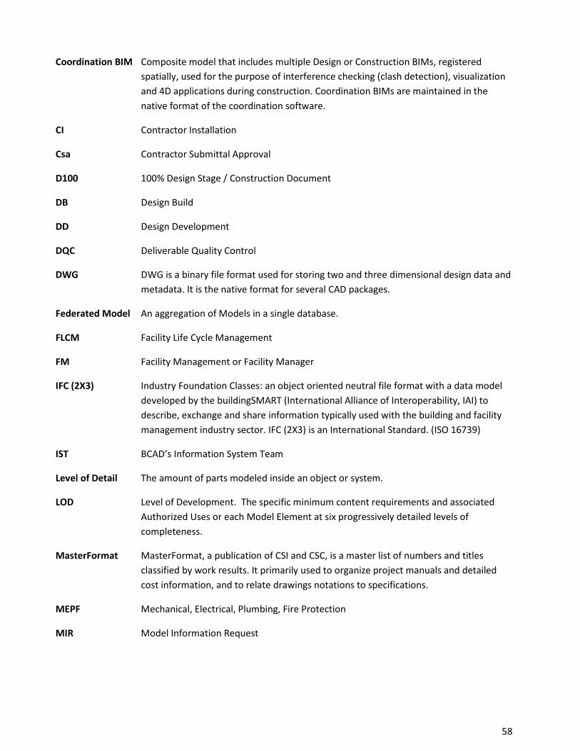
Coordination BIM Composite model that includes multiple Design or Construction BIMs, registered spatially, used for the purpose of interference checking (clash detection), visualization and 4D applications during construction. Coordination BIMs are maintained in the native format of the coordination software.
CI Contractor Installation
Csa Contractor Submittal Approval
D100 100% Design Stage / Construction Document
DB Design Build
DD Design Development
DQC Deliverable Quality Control
DWG DWG is a binary file format used for storing two and three dimensional design data and metadata. It is the native format for several CAD packages.
Federated Model An aggregation of Models in a single database.
FLCM Facility Life Cycle Management
FM Facility Management or Facility Manager
IFC (2X3) Industry Foundation Classes: an object oriented neutral file format with a data model developed by the buildingSMART (International Alliance of Interoperability, IAI) to describe, exchange and share information typically used with the building and facility management industry sector. IFC (2X3) is an International Standard. (ISO 16739)
IST BCAD’s Information System Team
Level of Detail The amount of parts modeled inside an object or system.
LOD Level of Development. The specific minimum content requirements and associated Authorized Uses or each Model Element at six progressively detailed levels of completeness.
MasterFormat MasterFormat, a publication of CSI and CSC, is a master list of numbers and titles classified by work results. It primarily used to organize project manuals and detailed cost information, and to relate drawings notations to specifications.
MEPF Mechanical, Electrical, Plumbing, Fire Protection
MIR Model Information Request
No portion of this work may be reproduced without the express written permission of the copyright holders. All rights reserved Broward County Aviation Department
58
MPS Model Progression Schedule (MPS) also known as the Model Element Table as referenced in the AIA G202 document and is a matrix that defines specific model elements by Uniformat classification.
NBIMS National Building Information Modeling Standard- United States, Version 2 (NBIMS-US v2)
OmniClass OmniClass Construction Classification System – Open Source- is a classification system for the construction industry. It incorporates other extant systems currently in use as the basis of many of its Tables – MasterFormat for work results and UniFormat for elements.
PxP Project Execution Plan
Record BIM The updated BIMS that come from the architect that includes the contractors AS Constructed BIMS.
RFI Request for Information
RFP Request for Proposal
RFQ Request for Qualifications
RP Responsible Party
SD Schematic Design
VDC Virtual Design and Construction
VDCO Virtual Design Construction and Operation (VDCO)
No portion of this work may be reproduced without the express written permission of the copyright holders. All rights reserved Broward County Aviation Department
59
14. Credits Primary References: National Building Information Modeling Standard- United States, Version 2 (NBIMS-US v2) Department of Veterans Affairs – The VA BIM Guide, v. 1.0 April 2010 Additional Reference: BIMForum’s 2013 Draft LOD Specification Broward Health BIM Standard BIM Standards Version 1, December 26, 2012 Construction Specification Institute (CSI) 2011 OmniClass Tables
Developed By: ACAI Associates, Inc.
Adolfo J. Cotilla, Jr. AIA, CGC - President
Alix Loiseau, CM-BIM, LEED AP – Director of VDC
Birgitta Foster, BSME, MBA – Director of Facility Integration
Cindy Baldwin, CGC, LEED AP, CM-BIM – Chief Operating Officer
David Thirlwell – BIM Manager
Randy Scott – Project Manager
Raul Rakela, AIA NCARB, CGC – Senior Architect
Acknowledgements:
ACAI Associates would like to thank all the individuals and organizations that participated, reviewed and contributed to this Standard.
bimSMART foundation – www.bimsmartfoundation.com
buildingSMART alliance – www.buildingsmartalliance.org
Stiles Corporation - Kris Lengieza CM-BIM – Director of Virtual Design and Construction
For further information about this Standard or to submit comments or questions, please visit contact:
BROWARD COUNTY AVIATION DEPARTMENT Mr. Marc Gambrill - Director of Capital Improvements Program (CIP) 100 Aviation Blvd Ft Lauderdale, FL 33315
No portion of this work may be reproduced without the express written permission of the copyright holders. All rights reserved Broward County Aviation Department
60

No portion of this work may be reproduced without the express written permission of the copyright holders.
All rights reserved Broward County Aviation Department


![CEHNY05XBT-281...^QV bcad`TSRSXRUSTZ ^[_P_P]_\PUYT /:Tjr4Ifhfg gggf mnopsjkrlq r](https://img.pdfslide.net/doc/110x75/60914dde0a3f011818472f90/cehny05xbt-281-qv-bcadtsrsxrustz-pppuyt-tjr4ifhfg-gggf-mnopsjkrlq.jpg)