Embed Size (px)
Citation preview
1May 2008Thrane & Thrane
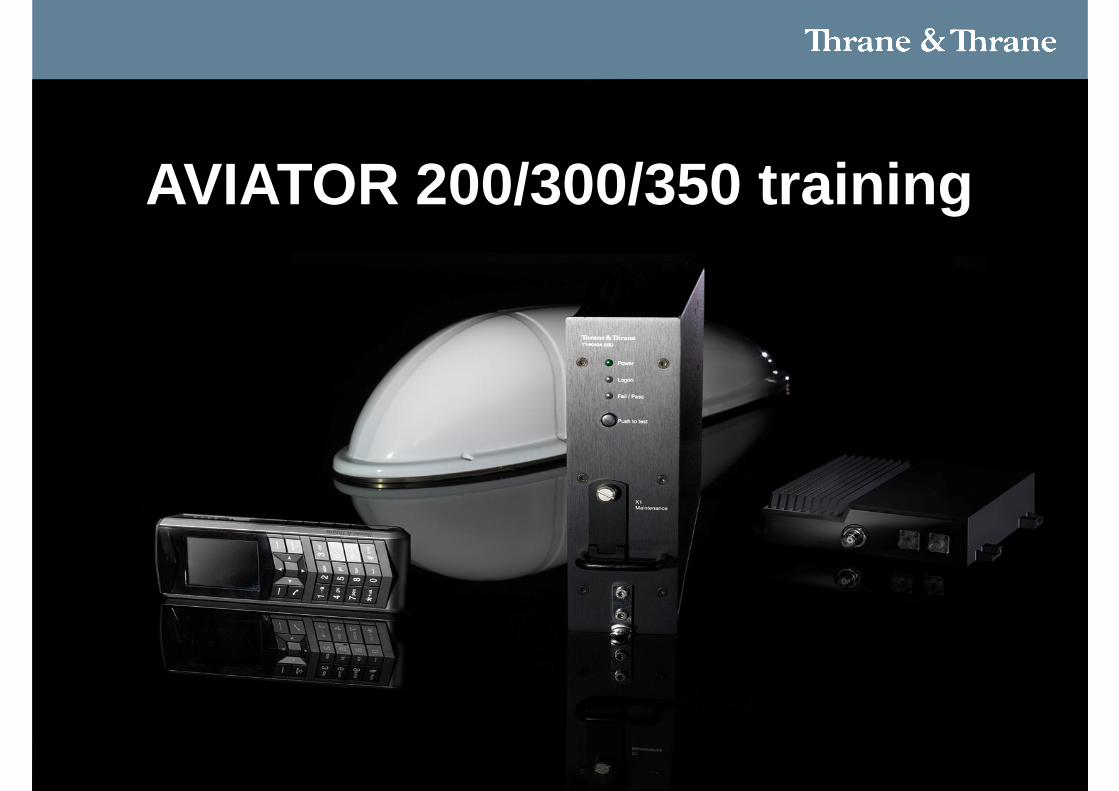
AVIATOR 200/300/350 training

Who is Thrane & Thrane?
Thrane & ThraneThe world’s leading mobile satellite
communications provider

414-12-2010T&T SwiftBroadband Solutions
• Largest Manufacturer of Inmarsat Terminals and Ground Stations
• 700 Employees World Wide• 300 R&D Engineers working with Inmarsat
Related Products• Has delivered 2/3 of all Inmarsat Terminals for
Land, Sea and Air• Has developed and delivered the entire Ground
Infrastructure for the Global Inmarsat BroadbandSystem

Thrane & Thrane Global Communication Solutions
for Aircraft

614-12-2010T&T SwiftBroadband Solutions
Tracking, Voice and Text Systems
Aero-C
Aero-I
Aero-M
Tracking and Text Messaging• Global Tracking System• Text Messaging and Fax
Voice Solution• Single Voice or Fax Channel
Voice and Cockpit Data System• 2 Voice Channels• 1 Cockpit Data Channel
714-12-2010T&T SwiftBroadband Solutions
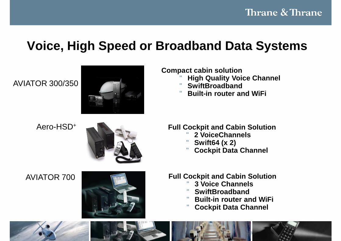
Voice, High Speed or Broadband Data Systems
Aero-HSD+
AVIATOR 300/350
AVIATOR 700
Compact cabin solution• High Quality Voice Channel• SwiftBroadband • Built-in router and WiFi
Full Cockpit and Cabin Solution• 3 Voice Channels• SwiftBroadband • Built-in router and WiFi• Cockpit Data Channel
Full Cockpit and Cabin Solution• 2 VoiceChannels• Swift64 (x 2) • Cockpit Data Channel
8
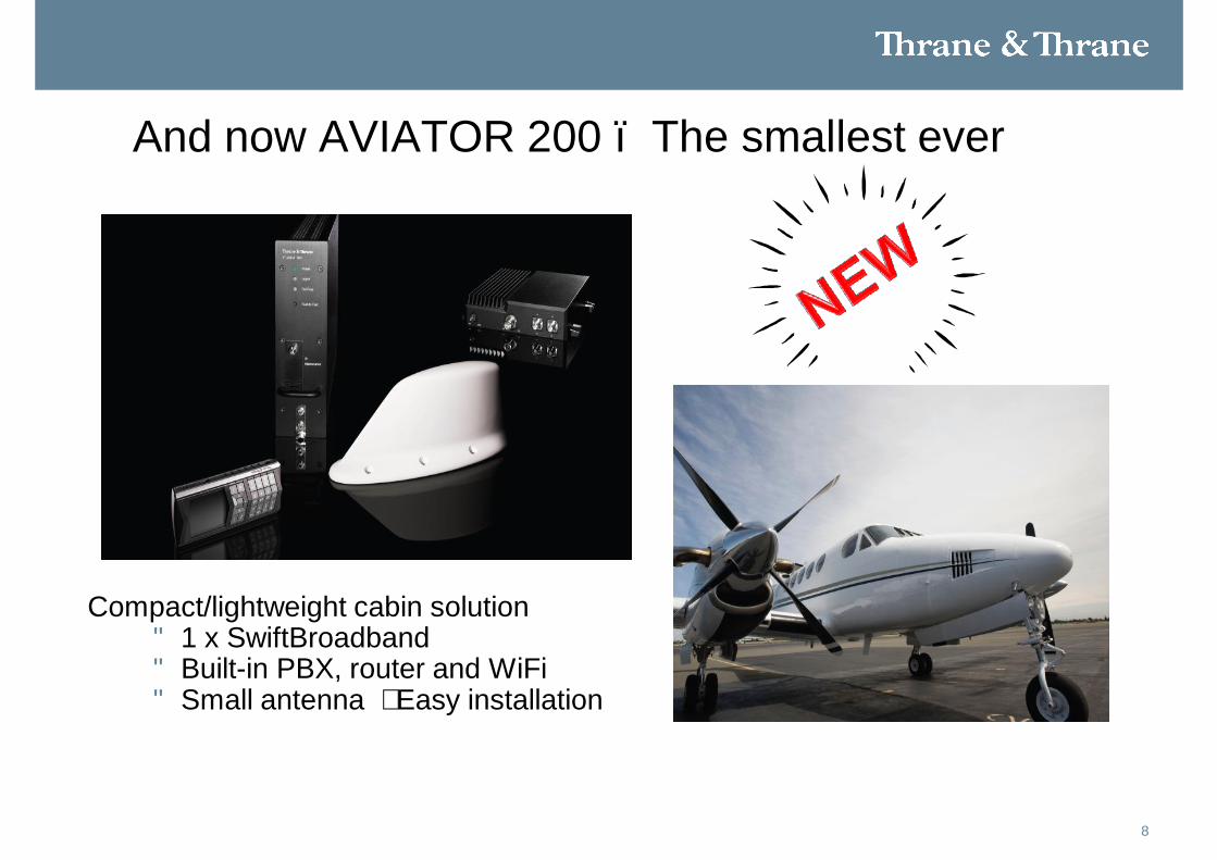
And now AVIATOR 200 – The smallest ever
Compact/lightweight cabin solution• 1 x SwiftBroadband • Built-in PBX, router and WiFi• Small antenna – Easy installation
9
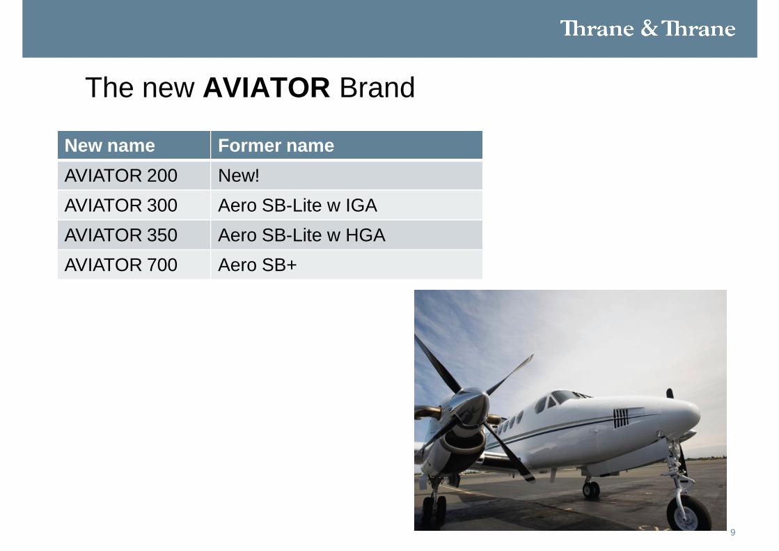
The new AVIATOR Brand
New name Former nameAVIATOR 200 New!AVIATOR 300 Aero SB-Lite w IGAAVIATOR 350 Aero SB-Lite w HGAAVIATOR 700 Aero SB+
Aero-HSD+
1114-12-2010T&T SwiftBroadband Solutions
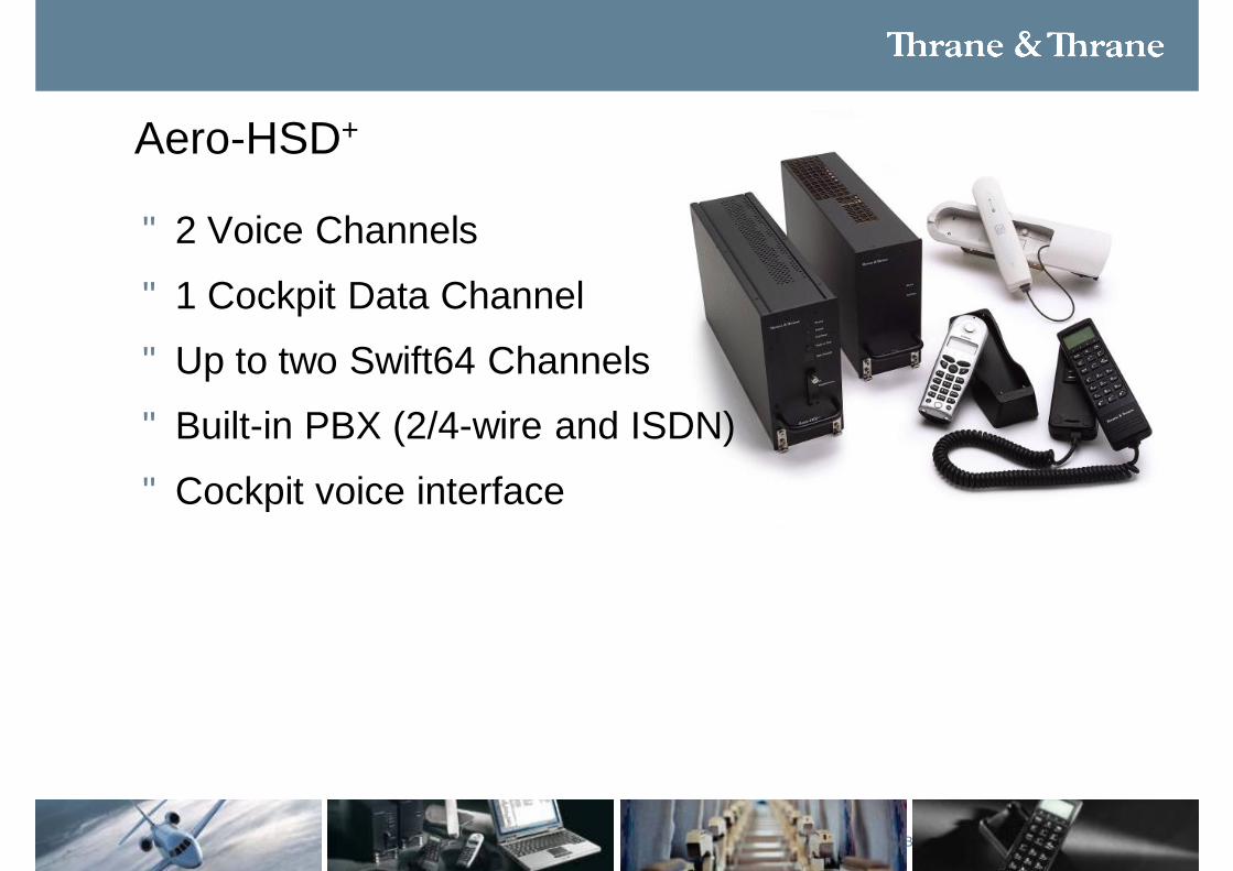
Aero-HSD+
• 2 Voice Channels
• 1 Cockpit Data Channel
• Up to two Swift64 Channels
• Built-in PBX (2/4-wire and ISDN)
• Cockpit voice interface
12
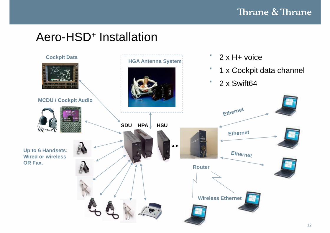
Wireless Ethernet
Router
• 2 x H+ voice
• 1 x Cockpit data channel
• 2 x Swift64
Aero-HSD+ Installation
Up to 6 Handsets:Wired or wirelessOR Fax.
Cockpit Data
SDU HPA HSU
HGA Antenna System
MCDU / Cockpit Audio
Aero SB-Lite
Now AVIATOR 300/350
1414-12-2010T&T SwiftBroadband Solutions
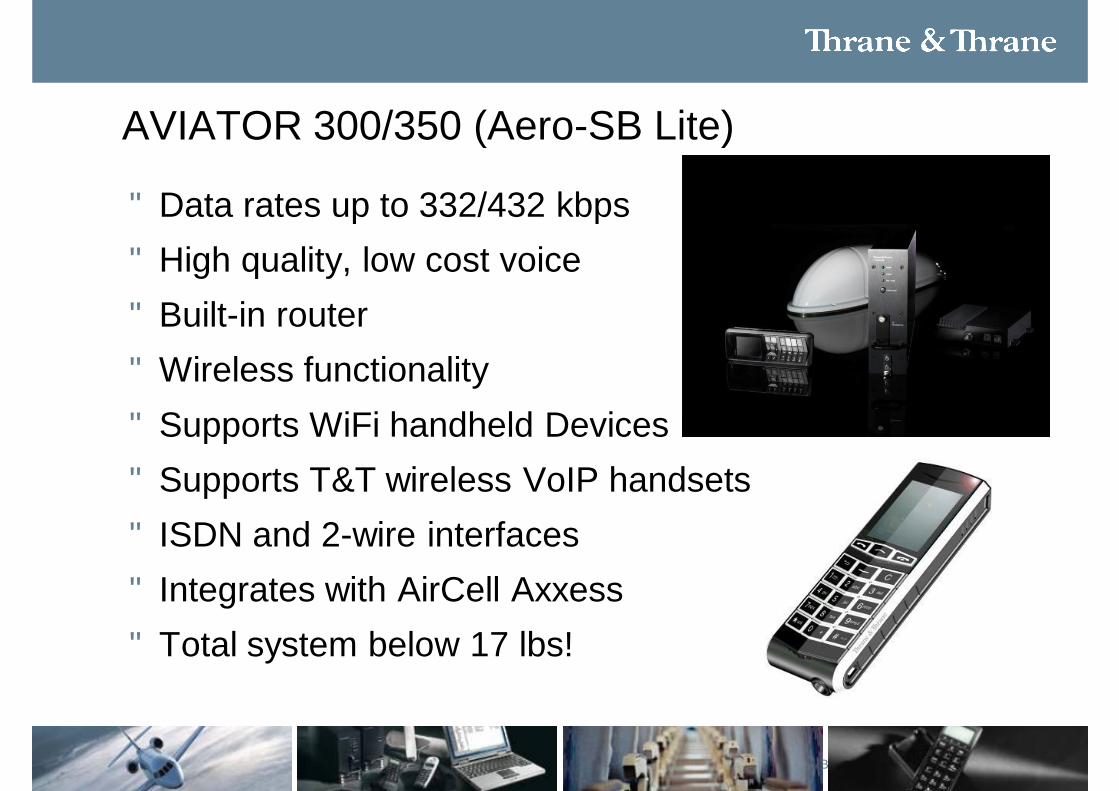
AVIATOR 300/350 (Aero-SB Lite)
• Data rates up to 332/432 kbps• High quality, low cost voice• Built-in router• Wireless functionality• Supports WiFi handheld Devices• Supports T&T wireless VoIP handsets• ISDN and 2-wire interfaces• Integrates with AirCell Axxess• Total system below 17 lbs!
1514-12-2010T&T SwiftBroadband Solutions
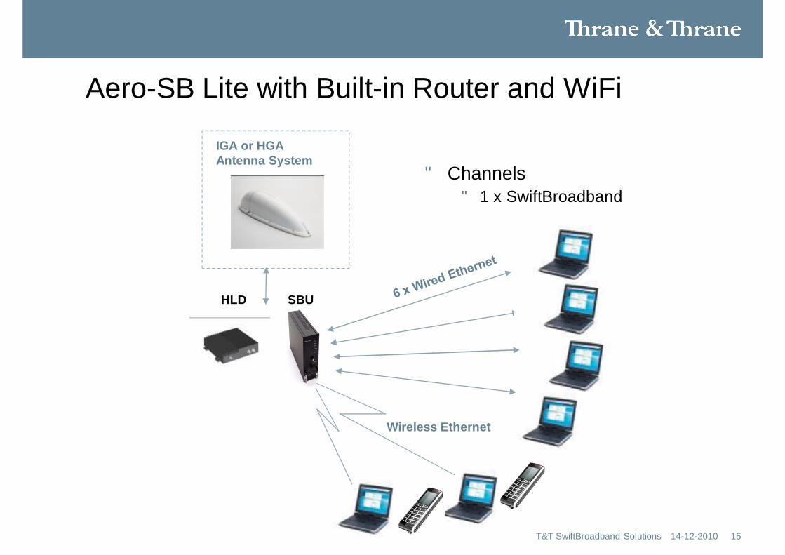
• Channels• 1 x SwiftBroadband
Aero-SB Lite with Built-in Router and WiFi
HLD SBU
IGA or HGAAntenna System
Wireless Ethernet
Aero-SB+
Now AVIATOR 700
1714-12-2010T&T SwiftBroadband Solutions
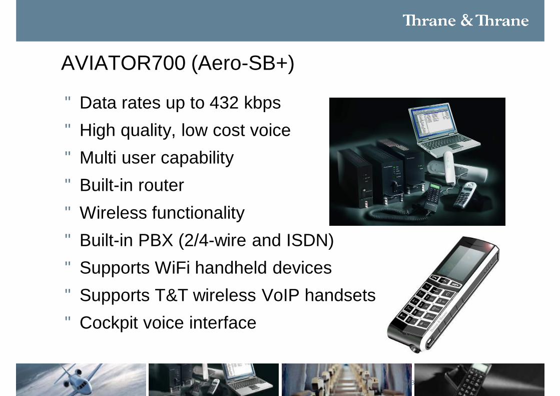
AVIATOR700 (Aero-SB+)
• Data rates up to 432 kbps• High quality, low cost voice• Multi user capability• Built-in router• Wireless functionality• Built-in PBX (2/4-wire and ISDN)• Supports WiFi handheld devices• Supports T&T wireless VoIP handsets• Cockpit voice interface
18
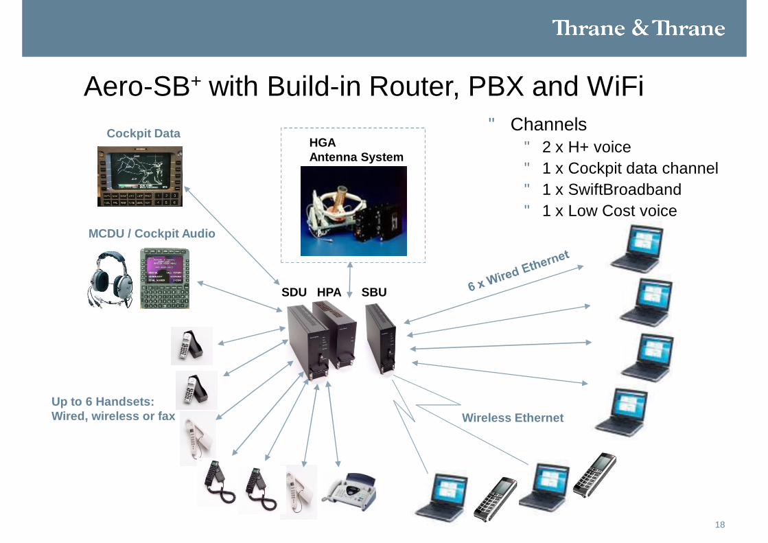
• Channels• 2 x H+ voice• 1 x Cockpit data channel• 1 x SwiftBroadband• 1 x Low Cost voice
Aero-SB+ with Build-in Router, PBX and WiFi
Up to 6 Handsets:Wired, wireless or fax
Cockpit Data
SDU HPA SBU
HGAAntenna System
MCDU / Cockpit Audio
Wireless Ethernet

1914-12-2010Skriv titel på præsentation
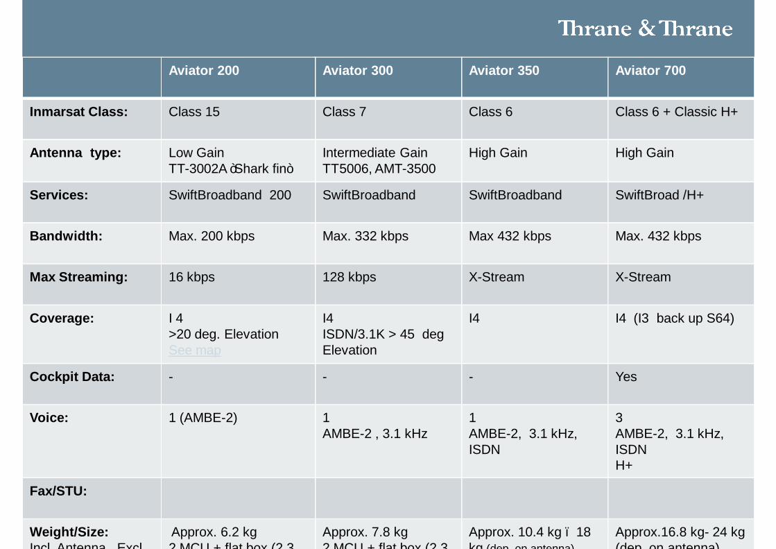
Aviator 200 Aviator 300 Aviator 350 Aviator 700
Inmarsat Class: Class 15 Class 7 Class 6 Class 6 + Classic H+
Antenna type: Low GainTT-3002A ”Shark fin”
Intermediate GainTT5006, AMT-3500
High Gain High Gain
Services: SwiftBroadband 200 SwiftBroadband SwiftBroadband SwiftBroad /H+
Bandwidth: Max. 200 kbps Max. 332 kbps Max 432 kbps Max. 432 kbps
Max Streaming: 16 kbps 128 kbps X-Stream X-Stream
Coverage: I 4 >20 deg. ElevationSee map
I4 ISDN/3.1K > 45 degElevation
I4 I4 (I3 back up S64)
Cockpit Data: - - - Yes
Voice: 1 (AMBE-2) 1 AMBE-2 , 3.1 kHz
1AMBE-2, 3.1 kHz, ISDN
3AMBE-2, 3.1 kHz, ISDNH+
Fax/STU:
Weight/Size: Incl. Antenna , Excl
Approx. 6.2 kg2 MCU + flat box (2.3
Approx. 7.8 kg2 MCU + flat box (2.3
Approx. 10.4 kg – 18 kg (dep. on antenna)
Approx.16.8 kg- 24 kg(dep. on antenna)
Introduction to Inmarsat
21Thrane & Thrane
• Inmarsat
• The Satellites• Inmarsat-2• Inmarsat-3• Inmarsat-4
• Network Operation
• Service Providers/Gateway Operators
22Thrane & Thrane
Inmarsat - Background
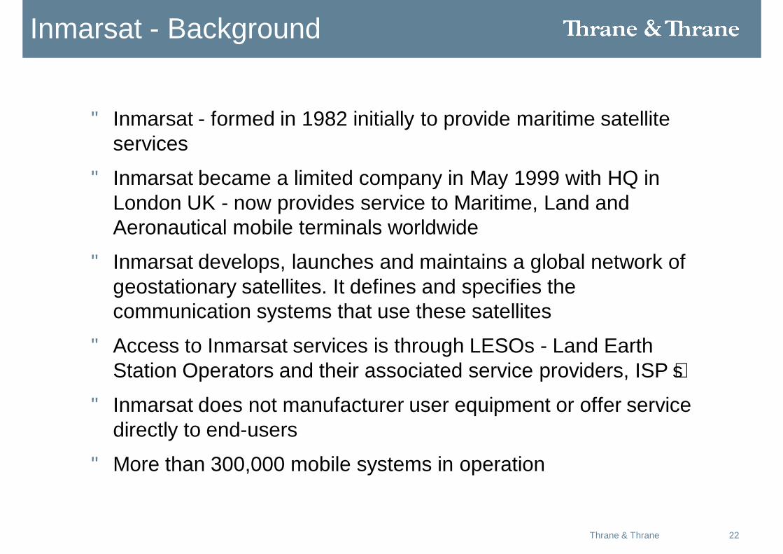
• Inmarsat - formed in 1982 initially to provide maritime satellite services
• Inmarsat became a limited company in May 1999 with HQ in London UK - now provides service to Maritime, Land and Aeronautical mobile terminals worldwide
• Inmarsat develops, launches and maintains a global network of geostationary satellites. It defines and specifies the communication systems that use these satellites
• Access to Inmarsat services is through LESOs - Land Earth Station Operators and their associated service providers, ISP’s
• Inmarsat does not manufacturer user equipment or offer service directly to end-users
• More than 300,000 mobile systems in operation
23Thrane & Thrane
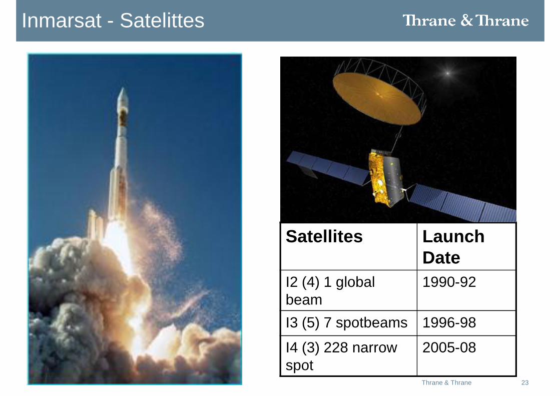
Inmarsat - Satelittes
Satellites Launch Date
I2 (4) 1 global beam
1990-92
I3 (5) 7 spotbeams 1996-98
I4 (3) 228 narrow spot
2005-08
24Thrane & Thrane
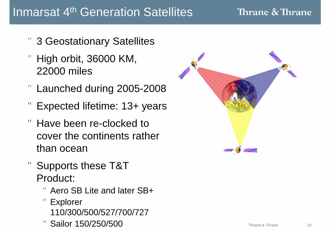
Inmarsat 4th Generation Satellites
• 3 Geostationary Satellites
• High orbit, 36000 KM, 22000 miles
• Launched during 2005-2008
• Expected lifetime: 13+ years
• Have been re-clocked to cover the continents rather than ocean
• Supports these T&T Product:• Aero SB Lite and later SB+ • Explorer
110/300/500/527/700/727• Sailor 150/250/500
25Thrane & Thrane
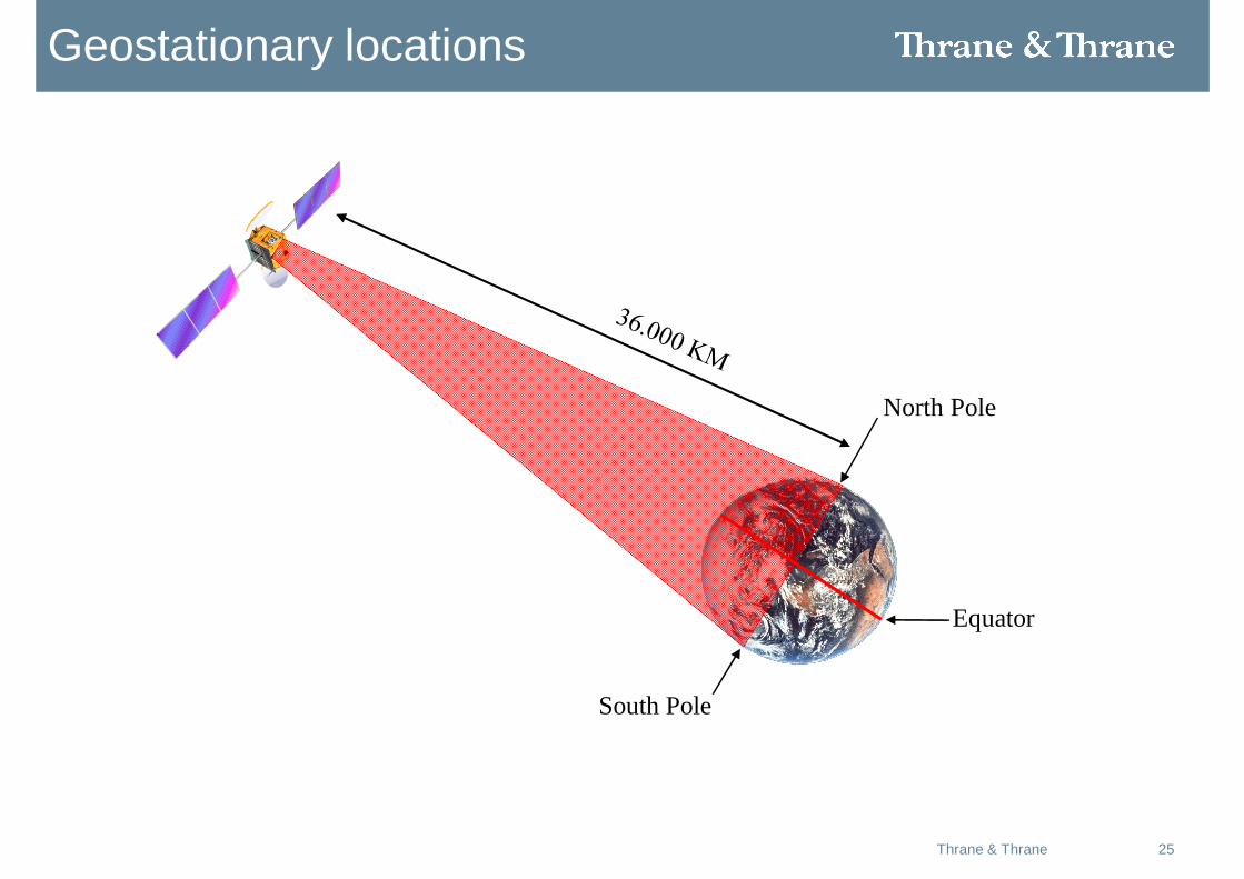
Equator
North Pole
South Pole
Geostationary locations
26Thrane & Thrane
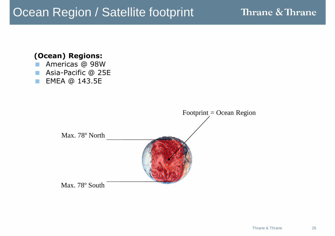
Max. 78º North
Max. 78º South
Footprint = Ocean Region
Ocean Region / Satellite footprint
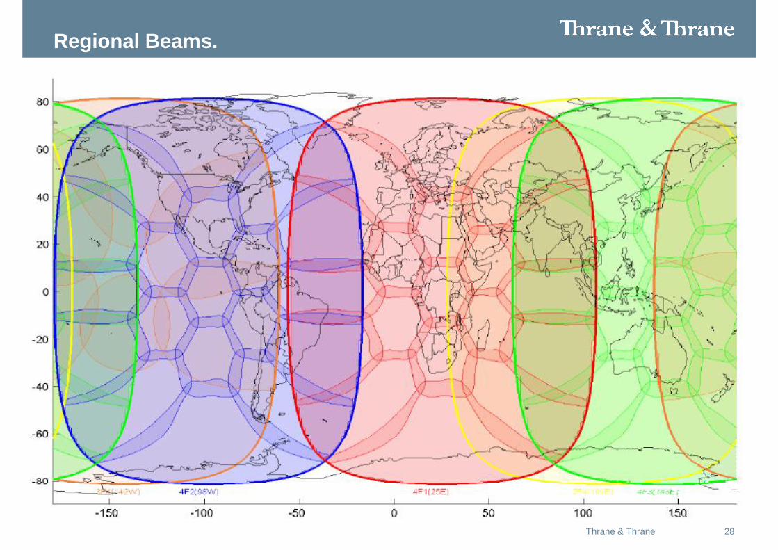
(Ocean) Regions:< Americas @ 98W< Asia-Pacific @ 25E< EMEA @ 143.5E
27Thrane & Thrane
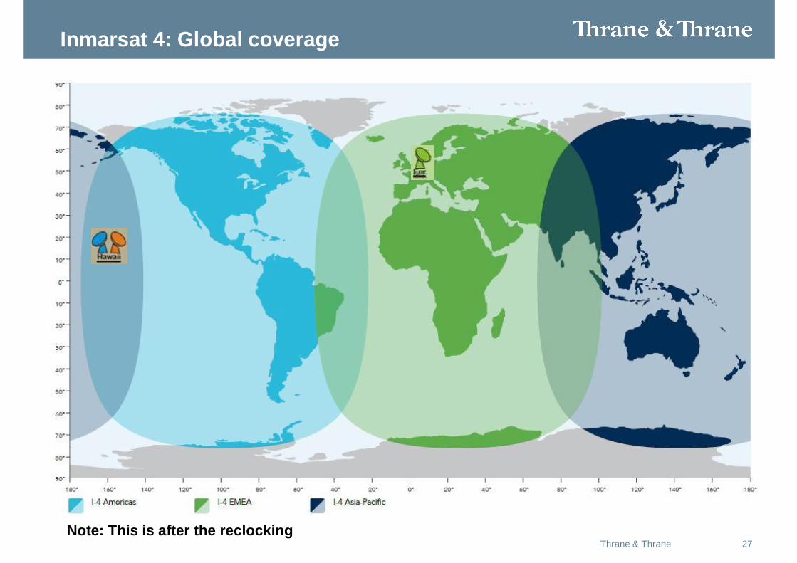
Inmarsat 4: Global coverage
Note: This is after the reclocking
28Thrane & Thrane
Regional Beams.
29Thrane & Thrane
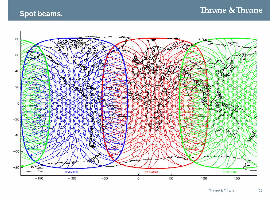
Spot beams.
30Thrane & Thrane
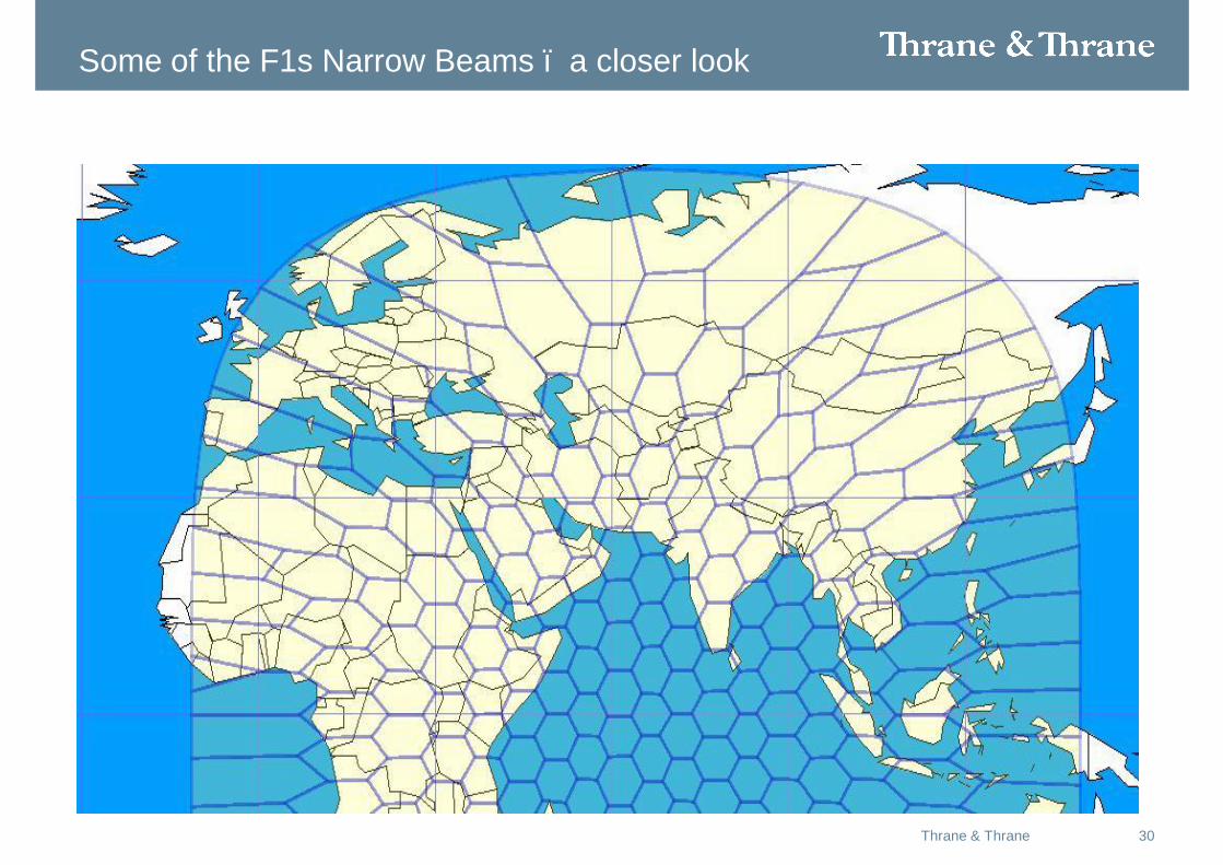
Some of the F1s Narrow Beams – a closer look
31Thrane & Thrane
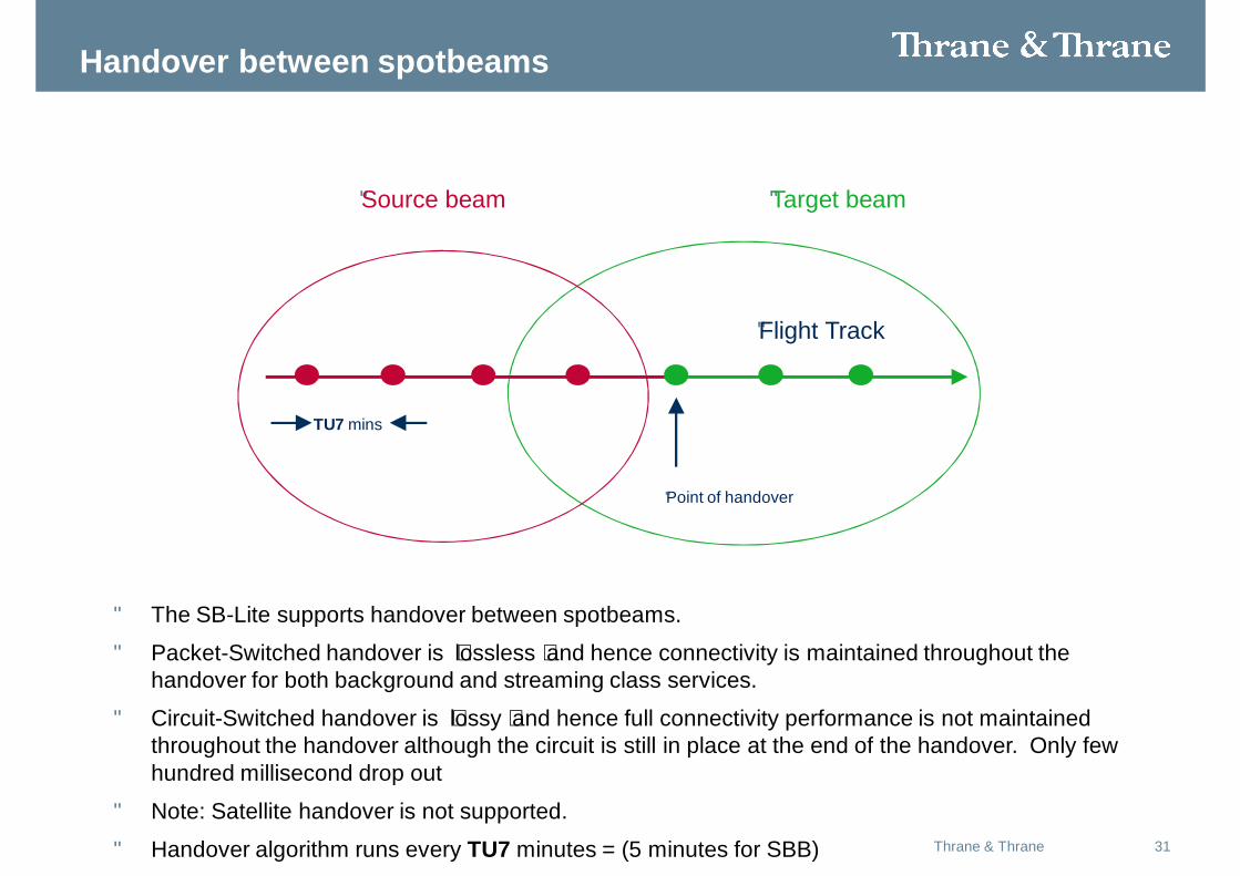
Handover between spotbeams
•Flight Track
•Source beam •Target beam
•Point of handover
TU7 mins
• The SB-Lite supports handover between spotbeams.
• Packet-Switched handover is ‘lossless’ and hence connectivity is maintained throughout the handover for both background and streaming class services.
• Circuit-Switched handover is ‘lossy’ and hence full connectivity performance is not maintained throughout the handover although the circuit is still in place at the end of the handover. Only few hundred millisecond drop out
• Note: Satellite handover is not supported.
• Handover algorithm runs every TU7 minutes = (5 minutes for SBB)
32Thrane & Thrane
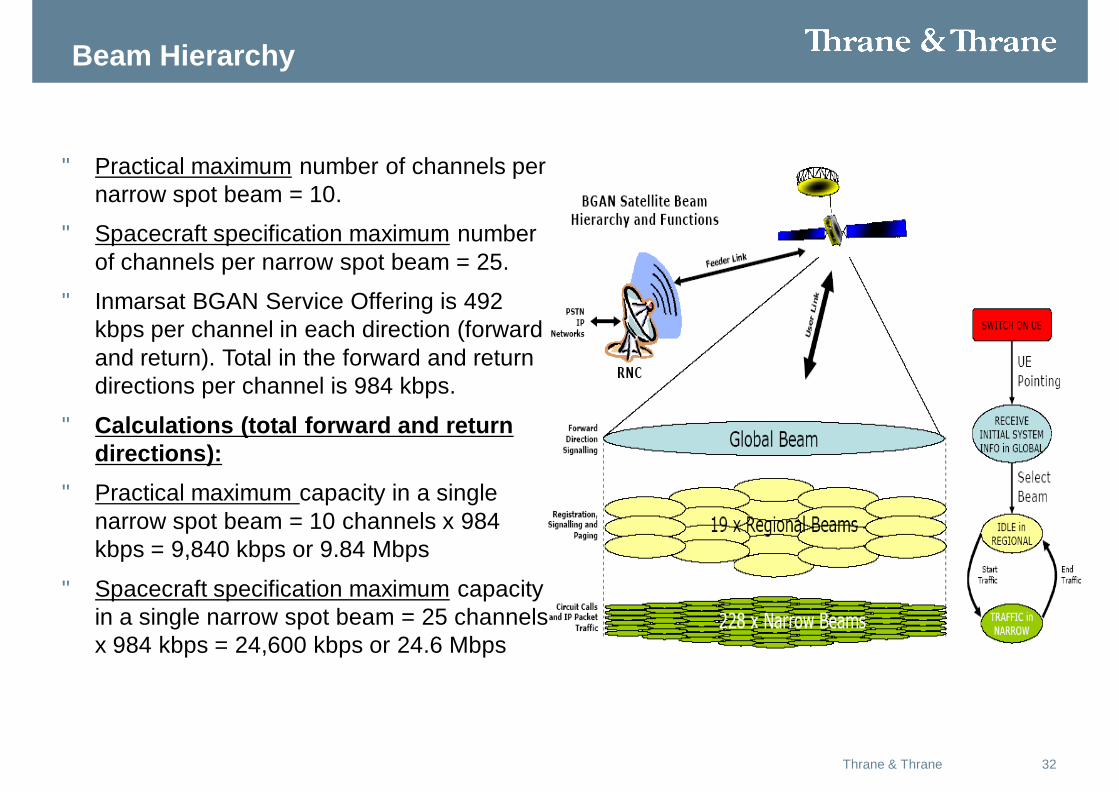
Beam Hierarchy
• Practical maximum number of channels per narrow spot beam = 10.
• Spacecraft specification maximum number of channels per narrow spot beam = 25.
• Inmarsat BGAN Service Offering is 492 kbps per channel in each direction (forward and return). Total in the forward and return directions per channel is 984 kbps.
• Calculations (total forward and return directions):
• Practical maximum capacity in a single narrow spot beam = 10 channels x 984 kbps = 9,840 kbps or 9.84 Mbps
• Spacecraft specification maximum capacity in a single narrow spot beam = 25 channels x 984 kbps = 24,600 kbps or 24.6 Mbps
33Thrane & Thrane
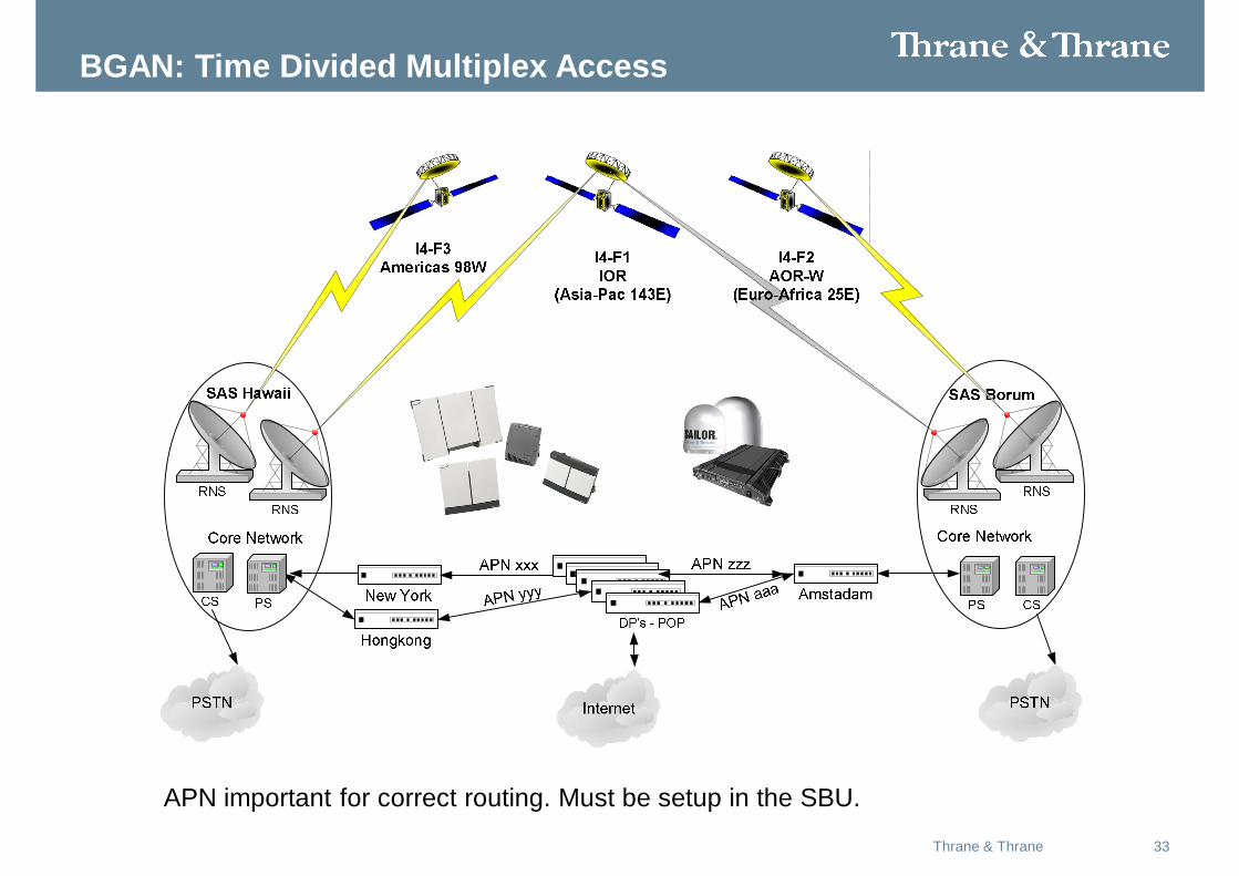
BGAN: Time Divided Multiplex Access
APN important for correct routing. Must be setup in the SBU.
34Thrane & Thrane
BusinessSupportSystems
BOC
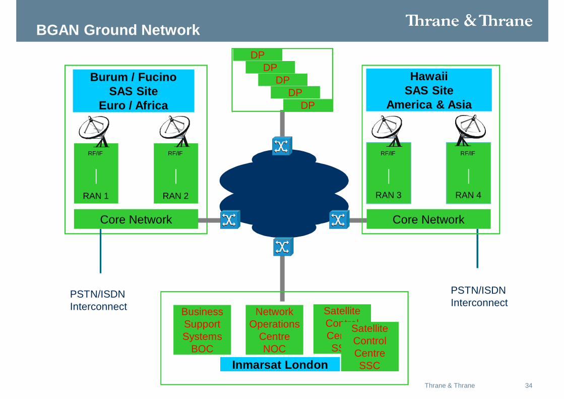
BGAN Ground Network
RAN 1
Burum / Fucino SAS Site
Euro / Africa
RAN 2
Inmarsat London
NetworkOperations
CentreNOC
SatelliteControlCentreSSC
PSTN/ISDNInterconnect
RF/IFRF/IF
Core Network
RAN 3
Hawaii SAS Site
America & Asia
RAN 4
RF/IFRF/IF
Core Network
PSTN/ISDNInterconnect
SatelliteControlCentreSSC
DPDP
DPDP
DP
35Thrane & Thrane
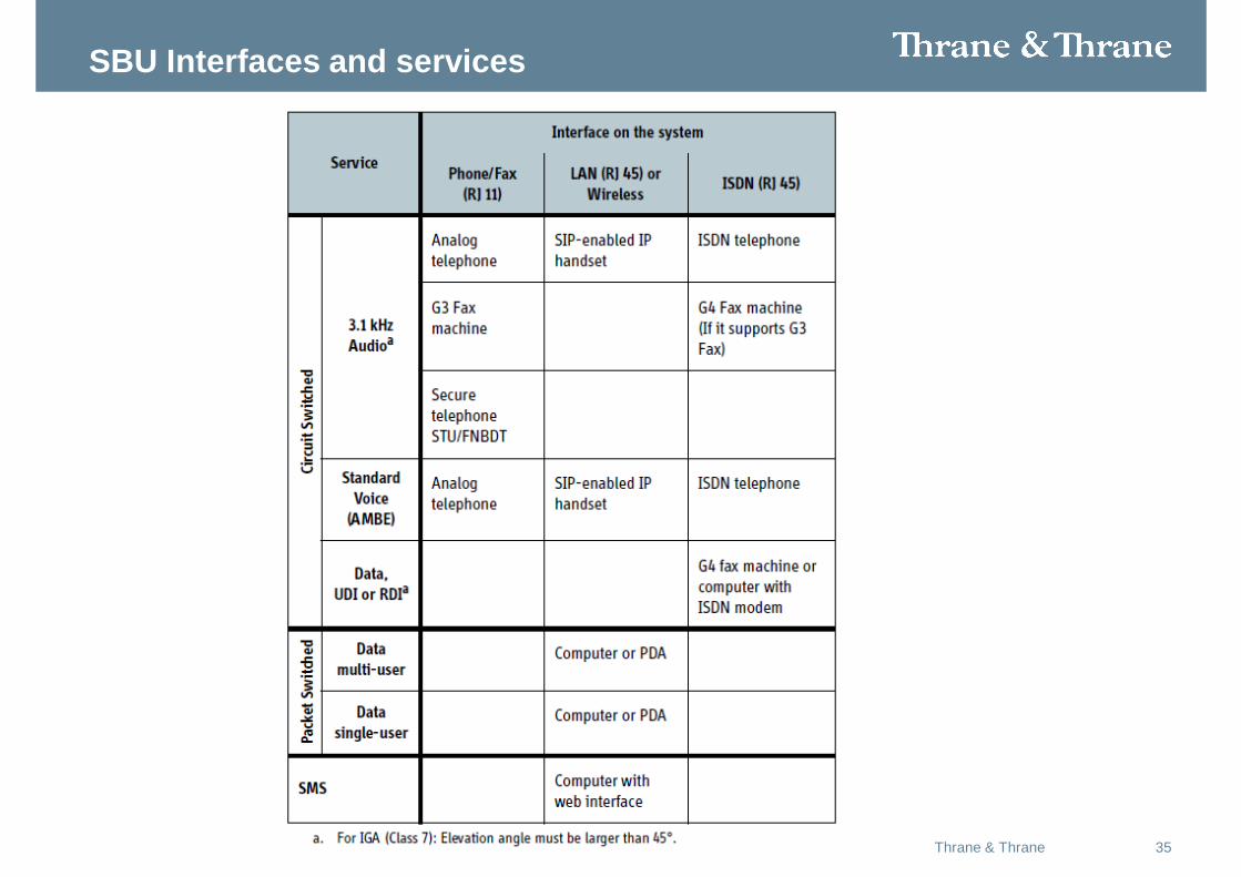
SBU Interfaces and services
36Thrane & Thrane
• The observed performance or speed of the IP data connection is influenced by many factors.
• The two different antenna sizes of the two classes will mean achievable data rates will differ. Essentially, the larger the antenna the greater the achievable bit rate, particularly in the uplink or return direction. Larger antennas will also enable higher bit rates in more demanding ‘edge of beam’ locations and should provide service to lower elevations to the satellite and in conditions of high fading (e.g. flight over calm ocean). In addition the performance of the antenna in terms of gain, G/T and ability to reject multipath will also affect the achievable bit rate. End users should also appreciate the number of users sharing the bearer at any particular time, will also impact achievable bit rate, along with at low elevation angles for a specific terminal/link conditions.
• Each 512kbps bearer needs to accommodate some system overheads, meaning the maximum theoretical bandwidth available for users will be 432kbps. As has been said previously, many factors will influence the achieved bit rate experienced by end users.
• Maximum 432 kbps RX:Maximum 432 kbps TX. High gain antenna (HGA)• Maximum 332 kbps RX: Maximum 332 kbps TX. Intermediate gain antenna (IGA)
37Thrane & Thrane
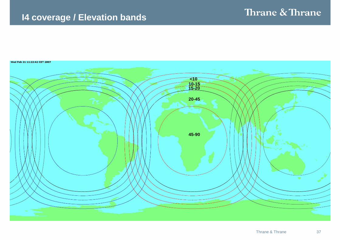
I4 coverage / Elevation bands
45-90
20-45
15-2010-15<10
38Thrane & Thrane
39Thrane & Thrane
40Thrane & Thrane
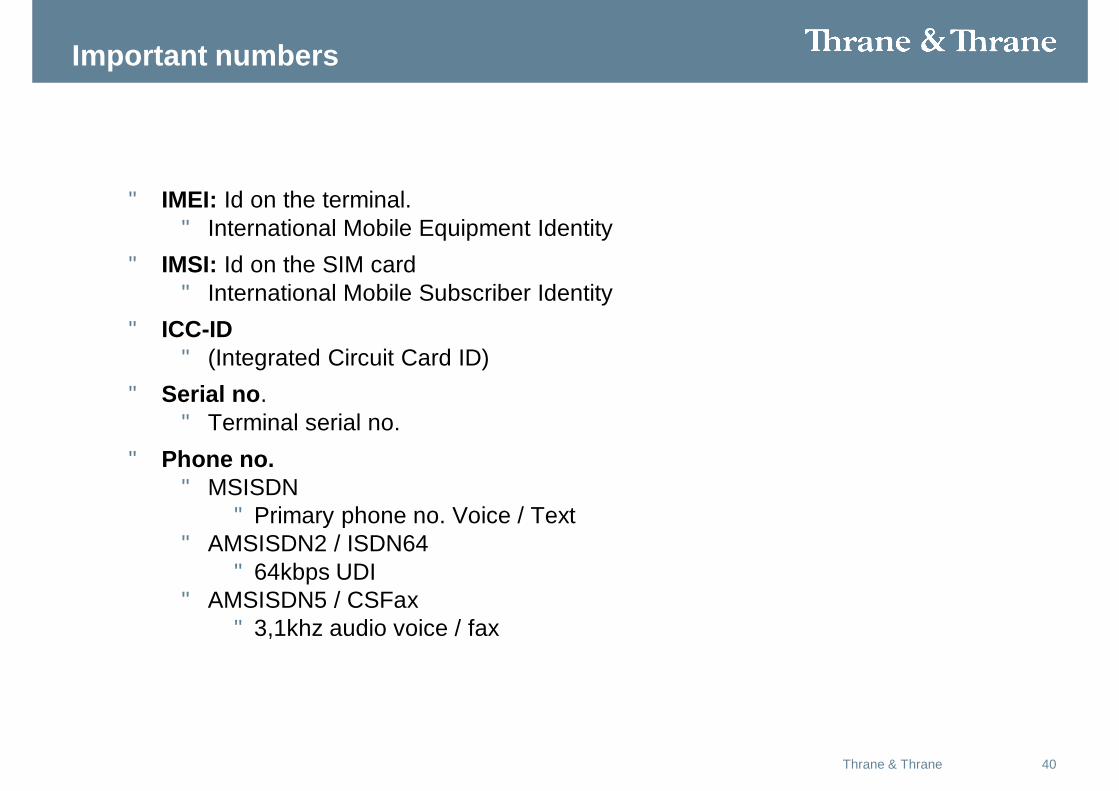
Important numbers
• IMEI: Id on the terminal. • International Mobile Equipment Identity
• IMSI: Id on the SIM card• International Mobile Subscriber Identity
• ICC-ID• (Integrated Circuit Card ID)
• Serial no. • Terminal serial no.
• Phone no.• MSISDN
• Primary phone no. Voice / Text• AMSISDN2 / ISDN64
• 64kbps UDI• AMSISDN5 / CSFax
• 3,1khz audio voice / fax
41Thrane & Thrane
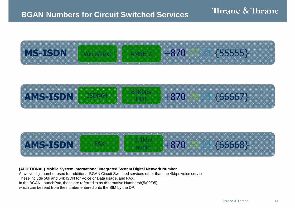
AMS-ISDN +870 7878 21 {66668}
BGAN Numbers for Circuit Switched Services
MS-ISDN +870 7777 21 {55555}Voice/Text AMBE-2
AMS-ISDN +870 7878 21 {66667}ISDN64
FAX
64Kbps UDI
3,1khz audio
(ADDITIONAL) Mobile System International Integrated System Digital Network NumberA twelve digit number used for additional BGAN Circuit Switched services other than the 4kbps voice service. These include 56k and 64k ISDN for Voice or Data usage, and FAX. In the BGAN LaunchPad, these are referred to as ‘Alternative Numbers’ (5/09/05), which can be read from the number entered onto the SIM by the DP.
42Thrane & Thrane
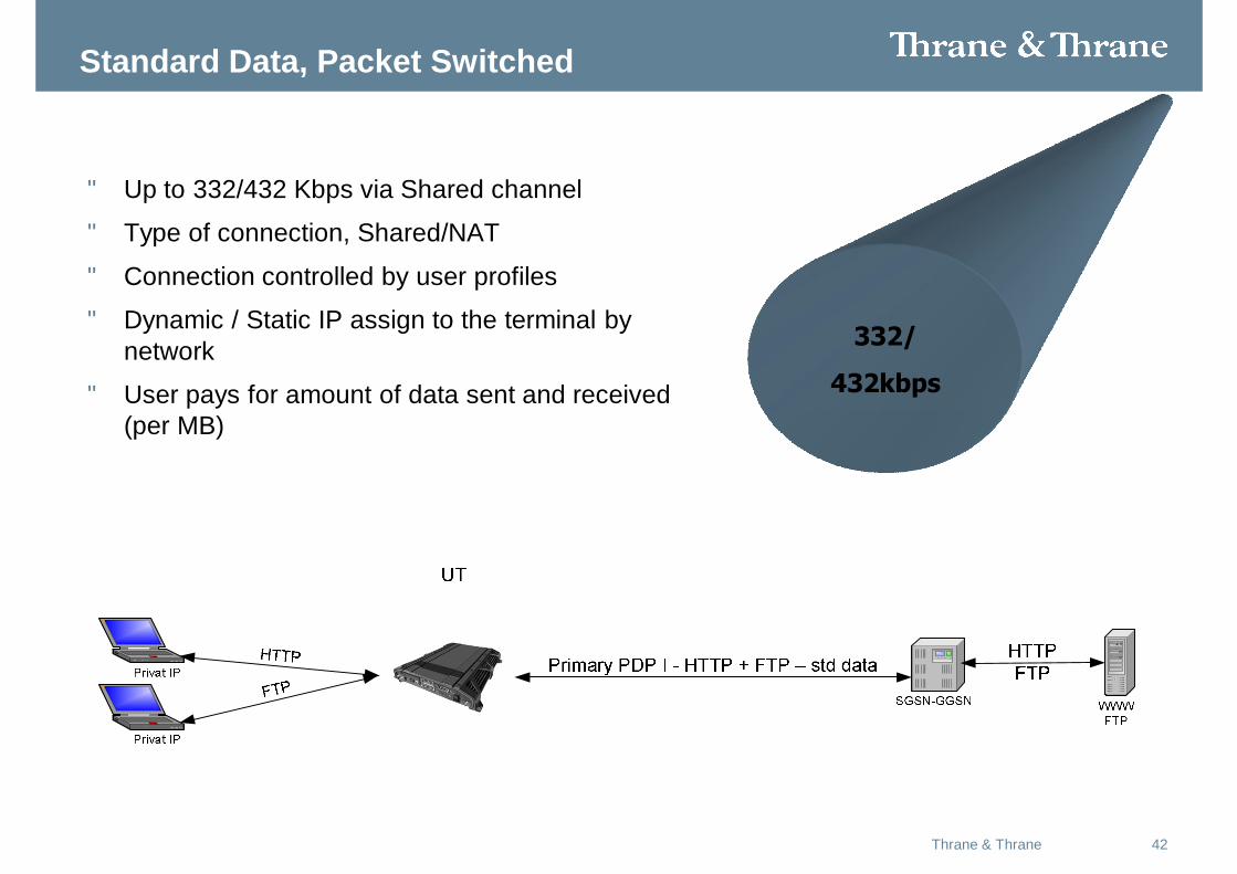
Standard Data, Packet Switched
• Up to 332/432 Kbps via Shared channel
• Type of connection, Shared/NAT
• Connection controlled by user profiles
• Dynamic / Static IP assign to the terminal by network
• User pays for amount of data sent and received (per MB)
332/
432kbps
43Thrane & Thrane
A variable bit rate IP service. Capacity is allocated dynamically by the network on the basis of the user’s demand, the user’s current link quality and the competing demands of other users sharing the same channel. Users are typically charged on the basis of data transmitted and received rather than duration of connection. The background class connection provides default a reliable in-order delivery over the satellite (i.e. any data lost due to random errors on the radio link is automatically retransmitted and re-ordered). BER = 10^-3
Standard Data
Background class IP data offers users access to the shared, contended IP 512kbps channel .There will be no guarantees associated with the service other than the SwiftBroadband contention ratio. If the link is ‘busy’, with many active users then the observed bit rate will be lower than if the link is ‘quiet’ with little traffic. This standard service will suit most office type applications, internet access, file transfer, email, etc
44Thrane & Thrane
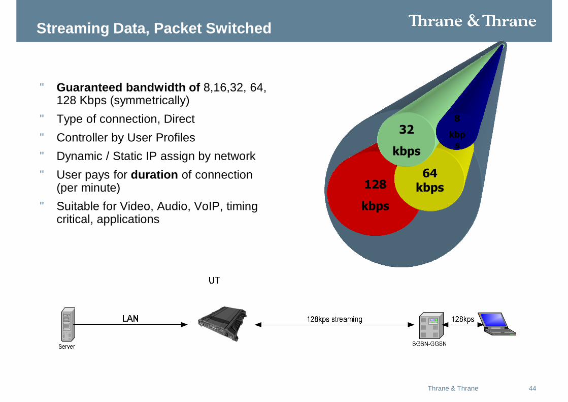
Streaming Data, Packet Switched
• Guaranteed bandwidth of 8,16,32, 64, 128 Kbps (symmetrically)
• Type of connection, Direct• Controller by User Profiles• Dynamic / Static IP assign by network• User pays for duration of connection
(per minute)• Suitable for Video, Audio, VoIP, timing
critical, applications
492kbps128
kbps
64 kbps
32
kbps
8
kbps
45Thrane & Thrane
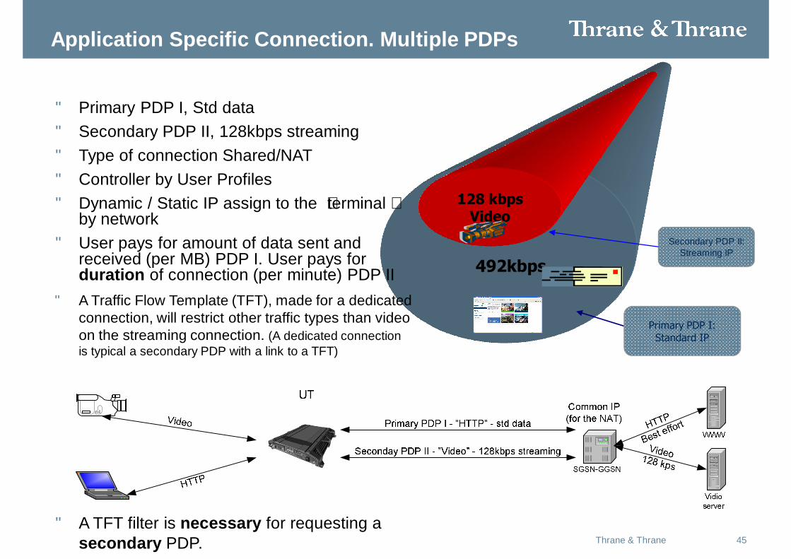
Application Specific Connection. Multiple PDPs
492kbps
Primary PDP I: Standard IP
128 kbps Video
Secondary PDP II: Streaming IP
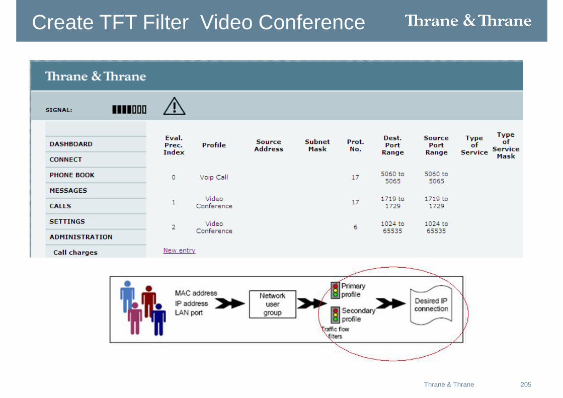
• Primary PDP I, Std data• Secondary PDP II, 128kbps streaming• Type of connection Shared/NAT• Controller by User Profiles• Dynamic / Static IP assign to the “terminal”
by network• User pays for amount of data sent and
received (per MB) PDP I. User pays for duration of connection (per minute) PDP II
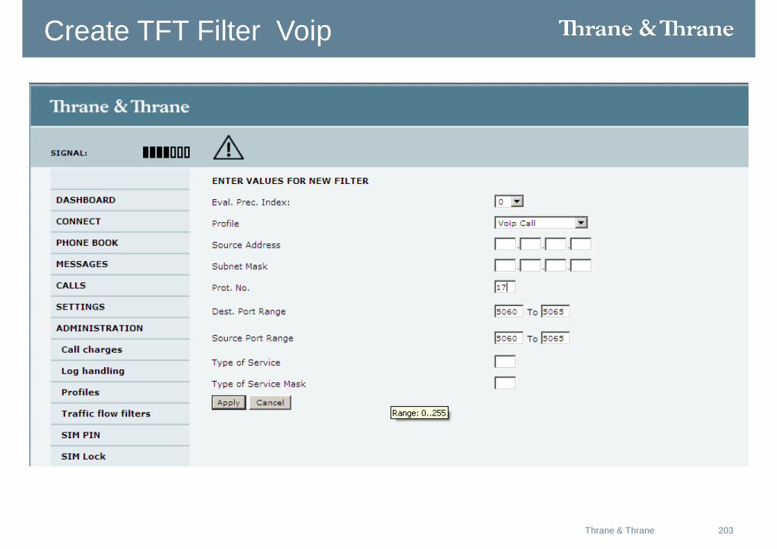
• A Traffic Flow Template (TFT), made for a dedicated connection, will restrict other traffic types than video on the streaming connection. (A dedicated connection is typical a secondary PDP with a link to a TFT)
• A TFT filter is necessary for requesting a secondary PDP.
46Thrane & Thrane
• The TFT (Traffic Flow Template) is used by the GGSN (Gateway GPRS Support Node)and the UT, to discriminate between different types of traffic (payload).
• The TFT incorporates a filter, witch discriminate the traffic based on IP address,Protocols, Ports, and TOS. Using the TFT filters the UTand GGSN maps the incomingtraffic into the correct Profile (PDPContext)
• Whenever using one or more SecondaryProfile (PDP Context), a TFT filer has to be linked to the Profile.
Secondary connections / Dedicated connections
47Thrane & Thrane
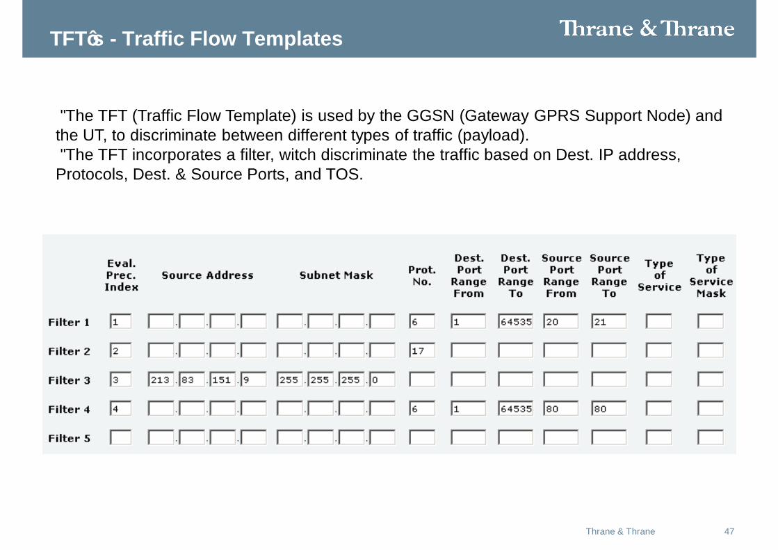
TFT’s - Traffic Flow Templates
• The TFT (Traffic Flow Template) is used by the GGSN (Gateway GPRS Support Node) and the UT, to discriminate between different types of traffic (payload). • The TFT incorporates a filter, witch discriminate the traffic based on Dest. IP address, Protocols, Dest. & Source Ports, and TOS.
48Thrane & Thrane
Link a TFT to a Profil (connection / PDP context)
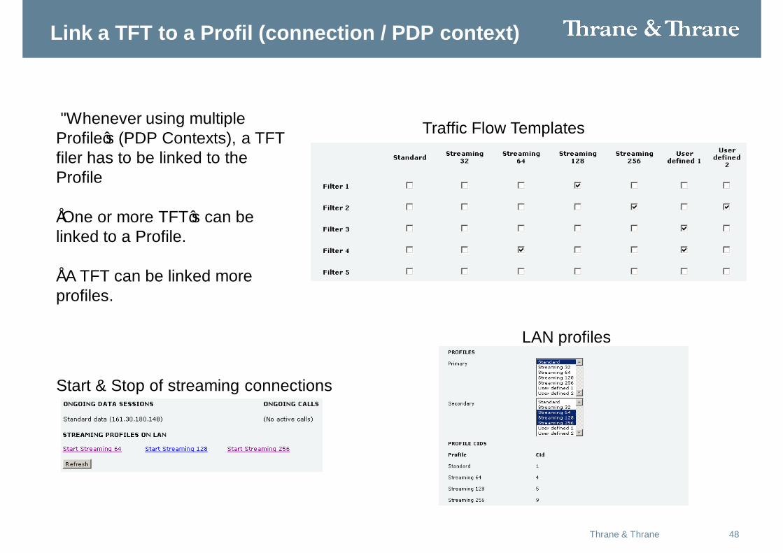
• Whenever using multiple Profile’s (PDP Contexts), a TFT filer has to be linked to the Profile
•One or more TFT’s can be linked to a Profile.
• A TFT can be linked more profiles.
Traffic Flow Templates
LAN profiles
Start & Stop of streaming connections
49Thrane & Thrane
Voice and Data, Circuit Switched
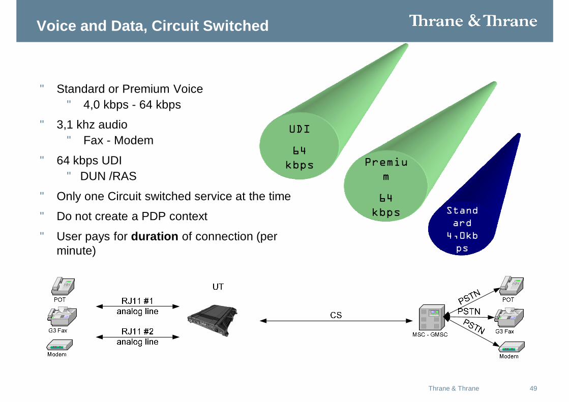
• Standard or Premium Voice • 4,0 kbps - 64 kbps
• 3,1 khz audio • Fax - Modem
• 64 kbps UDI• DUN /RAS
• Only one Circuit switched service at the time
• Do not create a PDP context
• User pays for duration of connection (per minute)
UDI
64 kbps
Standard
4,0kbps
Premium
64 kbps

50May 2008Thrane & Thrane
Theory of Operation
51Thrane & Thrane
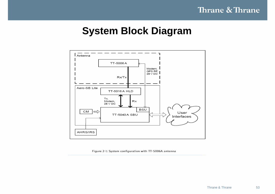
Overview of the Aero-SB Lite system
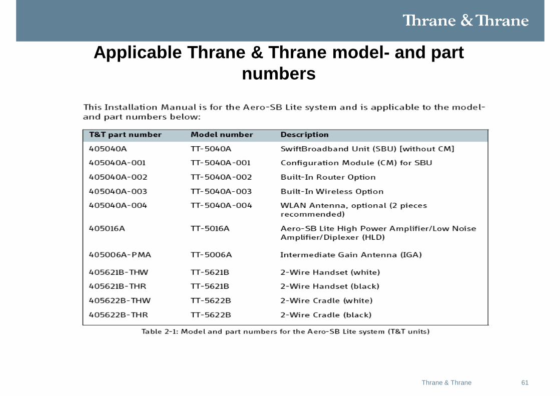
The Aero-SB Lite system is a compact, light-weight aeronautical satcom system that uses Inmarsat’s SwiftBroadband services.
The Aero-SB Lite system consists of the following units:
• • TT-5040A SBU (SwiftBroadband Unit)
• • TT-5040A-001 CM (Configuration Module), • inserted in the SBU and holds the SIM card.
• • TT-5016A HLD (High Power Amplifier, Low Noise Amplifier and Diplexer in one unit).
52Thrane & Thrane
Minimum system
• A minimum working system has at least:• • one TT-5040A SBU• • one TT-5040A-001 CM• • one TT-5016A HLD• • one IGA or HGA antenna, e.g. the TT-5006A IGA• The minimum wiring required for an Aero-SB Lite
system is described in the section Minimum system drawing on page 5-3 of the installation manual.
• The CM, HLD and IGA antenna are powered by the SBU.
53Thrane & Thrane
System Block Diagram
54Thrane & Thrane
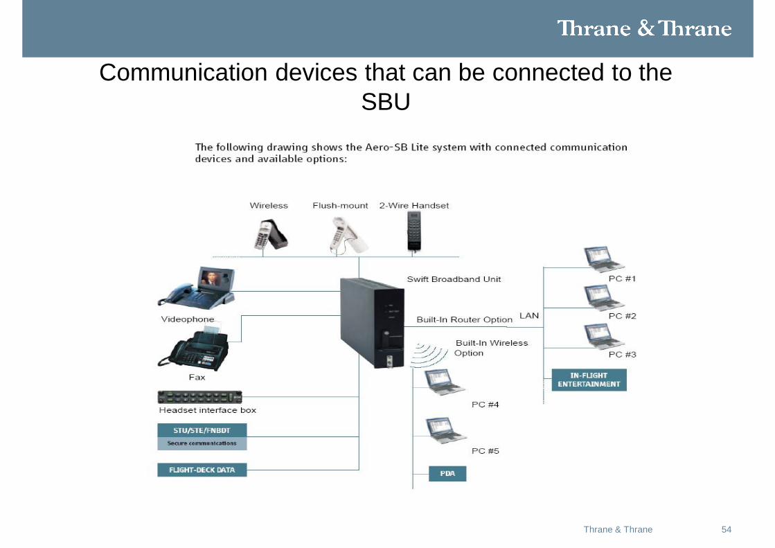
Communication devices that can be connected to the SBU
55Thrane & Thrane
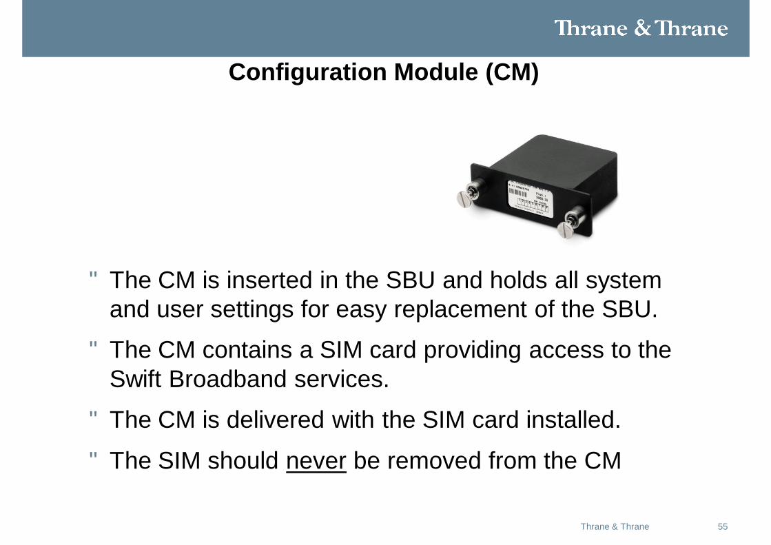
Configuration Module (CM)
• The CM is inserted in the SBU and holds all system and user settings for easy replacement of the SBU.
• The CM contains a SIM card providing access to the Swift Broadband services.
• The CM is delivered with the SIM card installed.
• The SIM should never be removed from the CM
56Thrane & Thrane
Standard features
• 1 SwiftBroadband channel providing a symmetric ‘always on’ data connection of up to 332 kbps for IGA and 432 kbps for an HGA.
• Modular design.
• Extremely small, compact and lightweight.
• 3.1 kHz audio (14.4 kbps) for modems, G3 fax, high quality voice etc.
• ISDN voice for Secure communication, G4 fax etc.
• ISDN data for video conferences etc, (only with HGA antenna).
57Thrane & Thrane
Standard features(cont)
• Built-In Router option with six Ethernet interfaces.
• Web interface for system configuration using the Maintenance connector on the SBU front plate.
• Built-In Wireless option, WLAN interface (WLAN) IEEE 802.11 b/g.
• Built-in PBX.
58Thrane & Thrane
Web interface for configuration
• Use the built-in web interface of the SBU to access the configuration settings in the CM.
• The configuration settings are stored in a write protected area of the CM.
• To change the configuration settings you must connect a PC to the connector marked Maintenance on the SBU front plate.
• You can view the configuration settings from any LAN interface.
59Thrane & Thrane
FLEx options: Built-in router and WiFi (WLAN)
• The Aero-SB Lite system offers a built-in router as an option. With this option multiple
• users and applications can use the system simultaneously.
• The system also offers a built-in WLAN option for wireless communication devices and a WLAN antenna approved for aeronautical use.
60Thrane & Thrane
PBX telephone exchange
• The built-in PBX telephone exchange unit of the SBU connects• Two 2-wire POTS interfaces
• Faxes, aux phones, headset interface boxes. • Two ISDN interface
• ISDN phones, fax machines or Secure communication• 16 VoIP handsets via SIP server & WLAN connection
• IP Handset, iPhone w SIP client etc.
61Thrane & Thrane
Applicable Thrane & Thrane model- and part numbers
62May 2008Thrane & Thrane
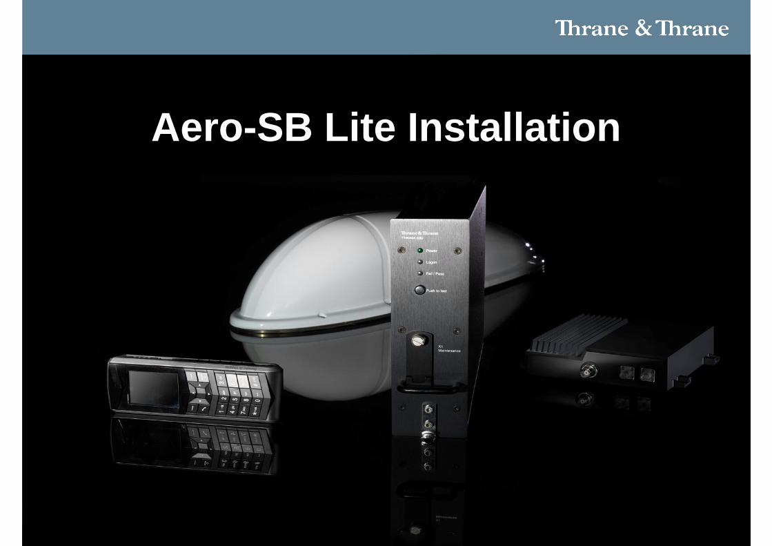
Aero-SB Lite Installation
63Thrane & Thrane
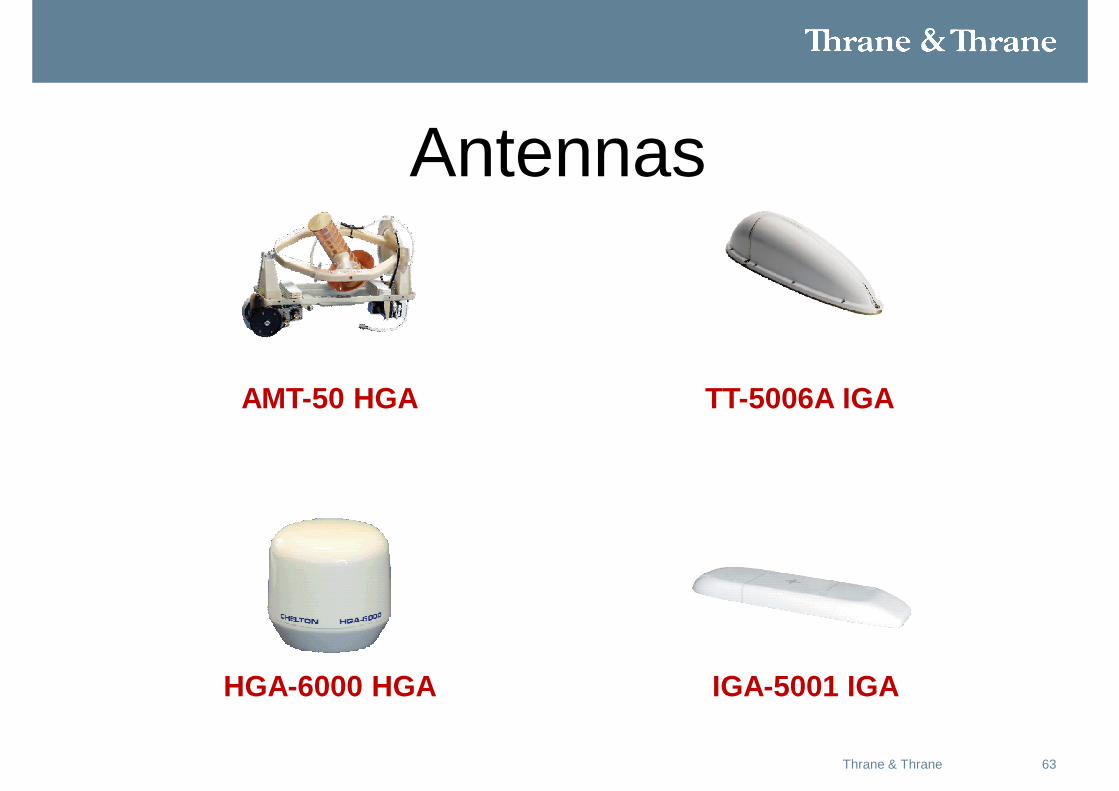
Antennas
AMT-50 HGA TT-5006A IGA
IGA-5001 IGA HGA-6000 HGA
64Thrane & Thrane
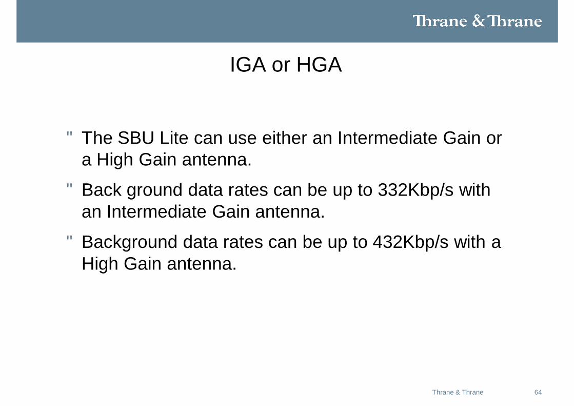
IGA or HGA
• The SBU Lite can use either an Intermediate Gain or a High Gain antenna.
• Back ground data rates can be up to 332Kbp/s with an Intermediate Gain antenna.
• Background data rates can be up to 432Kbp/s with a High Gain antenna.
6514-12-2010Skriv titel på præsentation
Aviator 200 Aviator 300 Aviator 350 Aviator 700
Inmarsat Class: Class 15 Class 7 Class 6 Class 6 + Classic H+
Antenna type: Low GainTT-3002A ”Shark fin”
Intermediate GainTT5006, AMT-3500
High Gain High Gain
Services: SwiftBroadband 200 SwiftBroadband SwiftBroadband SwiftBroad /H+
Bandwidth: Max. 200 kbps Max. 332 kbps Max 432 kbps Max. 432 kbps
Max Streaming: 16 kbps 128 kbps X-Stream X-Stream
Coverage: I 4 >20 deg. ElevationSee map
I4 ISDN/3.1K > 45 degElevation
I4 I4 (I3 back up S64)
Cockpit Data: - - - Yes
Voice: 1 (AMBE-2) 1 AMBE-2 , 3.1 kHz
1AMBE-2, 3.1 kHz, ISDN
3AMBE-2, 3.1 kHz, ISDNH+
Fax/STU:
Weight/Size: Incl. Antenna , Excl
Approx. 6.2 kg2 MCU + flat box (2.3
Approx. 7.8 kg2 MCU + flat box (2.3
Approx. 10.4 kg – 18 kg (dep. on antenna)
Approx.16.8 kg- 24 kg(dep. on antenna)
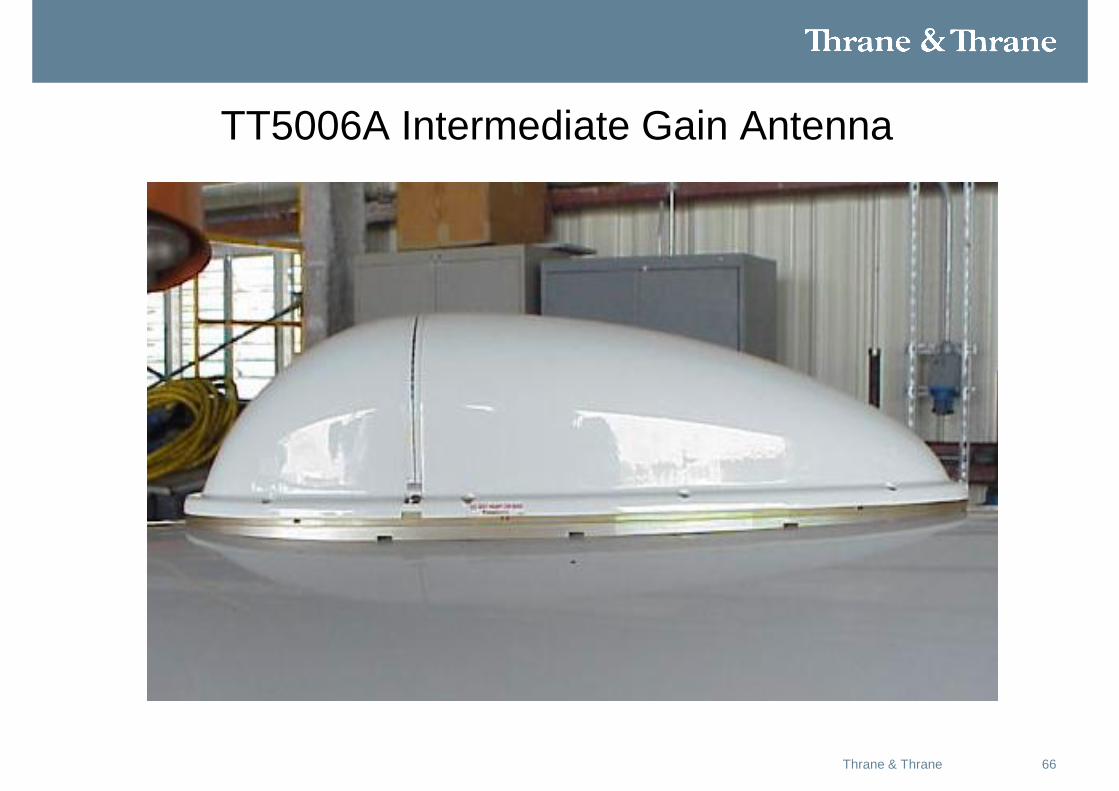
66Thrane & Thrane
TT5006A Intermediate Gain Antenna
67Thrane & Thrane
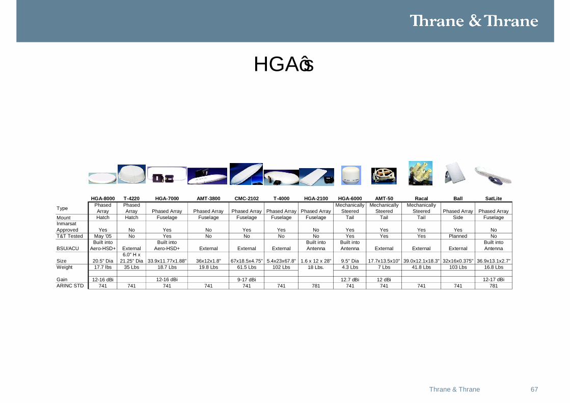
HGA’s
HGA-8000 T-4220 HGA-7000 AMT-3800 CMC-2102 T-4000 HGA-2100 HGA-6000 AMT-50 Racal Ball SatLite
Type Phased Array
Phased Array Phased Array Phased Array Phased Array Phased Array Phased Array
Mechanically Steered
Mechanically Steered
Mechanically Steered Phased Array Phased Array
Mount Hatch Hatch Fuselage Fuselage Fuselage Fuselage Fuselage Tail Tail Tail Side FuselageInmarsat Approved Yes No Yes No Yes Yes No Yes Yes Yes Yes NoT&T Tested May '05 No Yes No No No No Yes Yes Yes Planned No
BSU/ACUBuilt into
Aero-HSD+ ExternalBuilt into
Aero-HSD+ External External ExternalBuilt into Antenna
Built into Antenna External External External
Built into Antenna
Size 20.5" Dia6.0" H x
21.25" Dia 33.9x11.77x1.88" 36x12x1.8" 67x18.5x4.75" 5.4x23x67.8" 1.6 x 12 x 28" 9.5" Dia 17.7x13.5x10" 39.0x12.1x18.3" 32x16x0.375" 36.9x13.1x2.7"Weight 17.7 lbs 35 Lbs 18.7 Lbs 19.8 Lbs 61.5 Lbs 102 Lbs 4.3 Lbs 7 Lbs 41.8 Lbs 103 Lbs 16.8 Lbs
Gain 12-16 dBi 12-16 dBi 9-17 dBi 12.7 dBi 12 dBi 12-17 dBiARINC STD 741 741 741 741 741 741 781 741 741 741 741 781
18 Lbs.

AERO-SB Lite Antenna Installation Considerations
69Thrane & Thrane
Caution: Antenna Radiation
During Transmission, the antenna radiates micro wave energy from all sides. High levels of radio frequency radiation is considered harmful. When transmitting, personnel should stay a minimum of 4 feet from the antenna.
70Thrane & Thrane
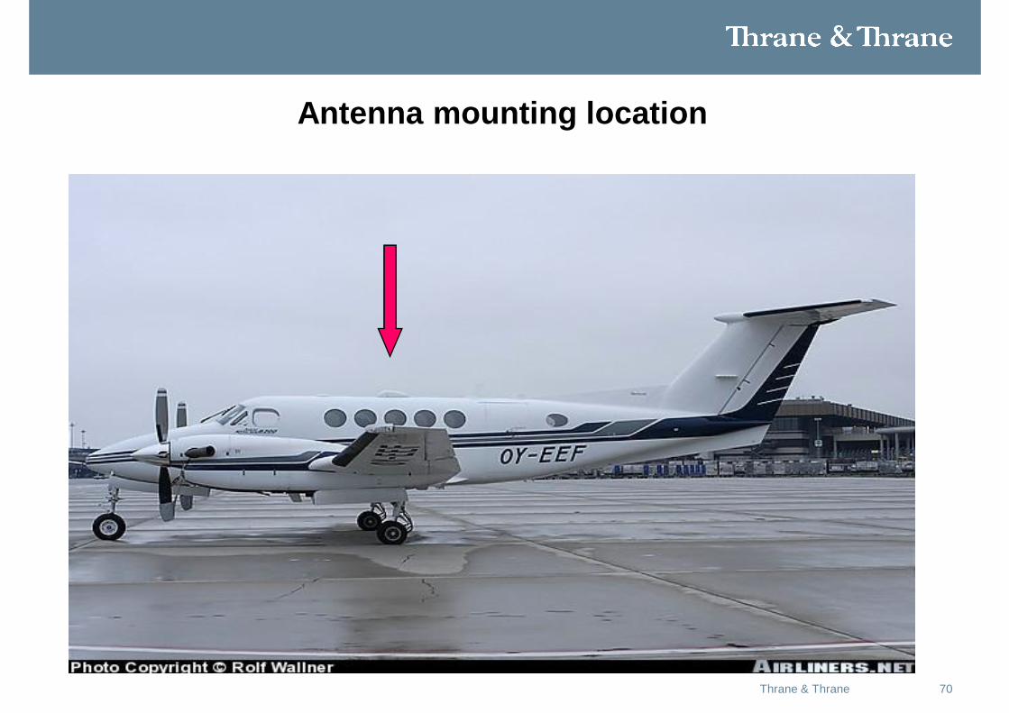
Antenna mounting location
71Thrane & Thrane
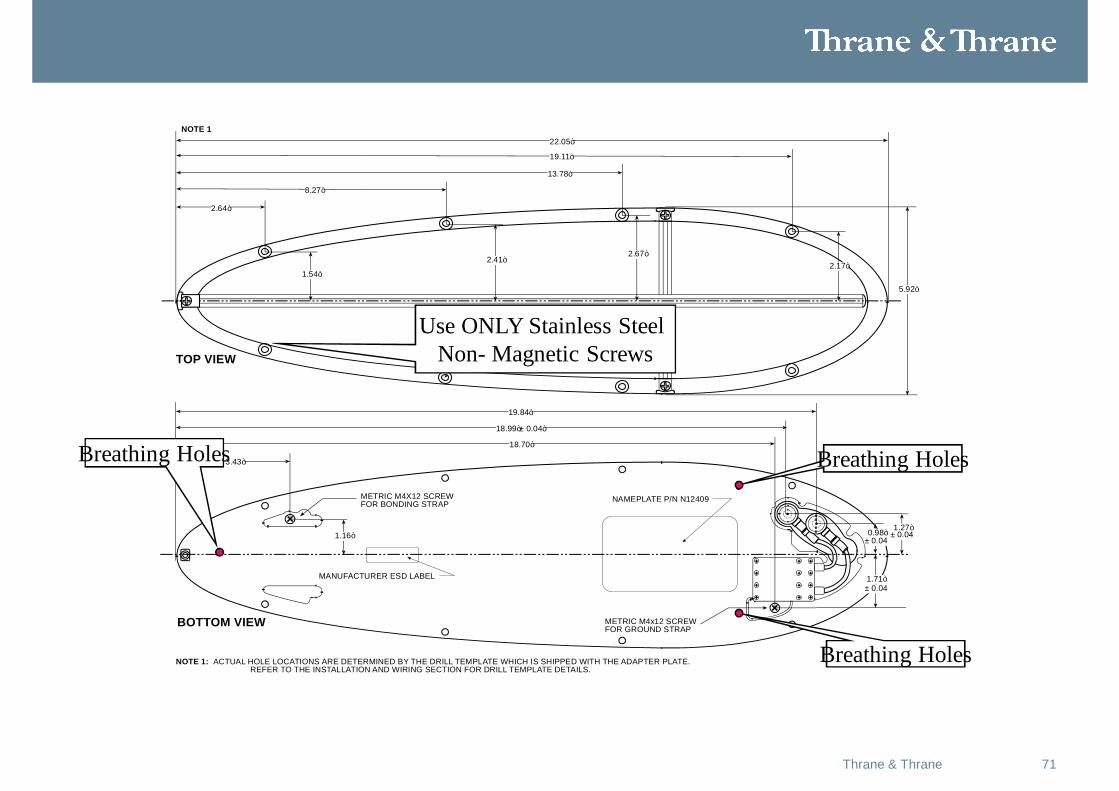
METRIC M4X12 SCREWFOR BONDING STRAP
METRIC M4x12 SCREWFOR GROUND STRAP
22.05”
19.11”
13.78”
8.27”
2.64”
1.54”
2.41”2.67”
2.17”
5.92”
19.84”
18.99”± 0.04”
18.70”
3.43”
1.16” 0.98” 1.27”
± 0.04
± 0.04± 0.04
1.71”
HOLE FOR #10-32 SCREW8 PLACES
TOP VIEW
BOTTOM VIEW
NOTE 1: ACTUAL HOLE LOCATIONS ARE DETERMINED BY THE DRILL TEMPLATE WHICH IS SHIPPED WITH THE ADAPTER PLATE.REFER TO THE INSTALLATION AND WIRING SECTION FOR DRILL TEMPLATE DETAILS.
NOTE 1
NAMEPLATE P/N N12409
MANUFACTURER ESD LABEL
Breathing Holes
Breathing Holes
Breathing Holes
Use ONLY Stainless Steel Non- Magnetic Screws
72Thrane & Thrane
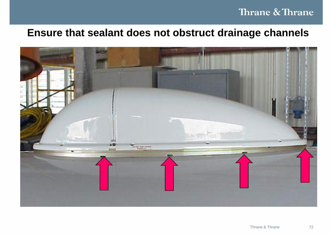
Ensure that sealant does not obstruct drainage channels
73Thrane & Thrane
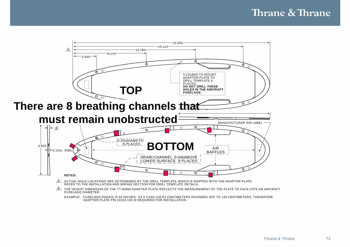
AIRBAFFLES0.12” ± .008”
5.90”
0.20” DIAMETER8 PLACES
DRAIN CHANNEL, 0.04” ABOVELOWER SURFACE. 8 PLACES
THE HEIGHT DIMENSION OF THE TT-5006A ADAPTER PLATE REFLECTS THE MEASUREMENT OF THE PLATE TO FACILITATE AN AIRCRAFTFUSELAGE DIAMETER.
22.09”
22.05”19.11”
13.78”8.27”
2.64”
0.12” (M4) TO MOUNTADAPTER PLATE TODRILL TEMPLATE 6PLACES.DO NOT DRILL THESEHOLES IN THE AIRCRAFTFUSELAGE.
EXAMPLE: FUSELAGE RADIUS IS 53 INCHES. 53 X 2.540=134.62 CENTIMETERS ROUNDED OFF TO 135 CENTIMETERS. THEREFORE ADAPTER PLATE P/N 10102-135 IS REQUIRED FOR INSTALLATION.
NOTES:
1 ACTUAL HOLE LOCATIONS ARE DETERMINED BY THE DRILL TEMPLATE WHICH IS SHIPPED WITH THE ADAPTER PLATE.REFER TO THE INSTALLATION AND WIRING SECTION FOR DRILL TEMPLATE DETAILS.
2
2
1
NAMPLATE P/N N12410 TOP AND BOTTOM MANUFACTURER S/N LABEL
There are 8 breathing channels thatmust remain unobstructed
TOP
BOTTOM
74Thrane & Thrane
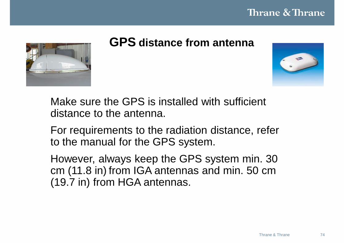
AERGPS distance from antennaO-M Antenna Installation
Make sure the GPS is installed with sufficient distance to the antenna. For requirements to the radiation distance, refer to the manual for the GPS system.However, always keep the GPS system min. 30 cm (11.8 in) from IGA antennas and min. 50 cm (19.7 in) from HGA antennas.
75Thrane & Thrane
Satcom filter
• If the GPS antenna for the existing GPS receiver on board the aircraft does not provide sufficient filtering it may be necessary to install a Satcom filter for the GPS antenna.
• Consult GPS manufacture for appropriate filter.
76Thrane & Thrane
Glonass distance from antenna
• Make sure your Glonass is installed with sufficient distance to the antenna.
• For requirements to the radiation distance, refer to the manual for the Glonass system.
• However, always keep the Glonass system min. 120 cm (47.2 in) from IGA antennas and min. 210 cm (82.7 in) from HGA antennas.
77Thrane & Thrane
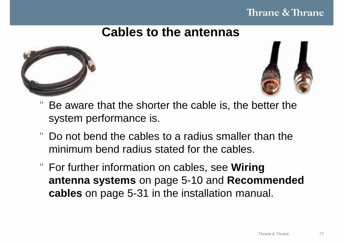
Cables to the antennas
• Be aware that the shorter the cable is, the better the system performance is.
• Do not bend the cables to a radius smaller than the minimum bend radius stated for the cables.
• For further information on cables, see Wiring antenna systems on page 5-10 and Recommended cables on page 5-31 in the installation manual.
78Thrane & Thrane
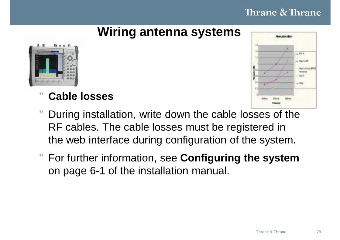
Wiring antenna systems
• Cable losses• During installation, write down the cable losses of the
RF cables. The cable losses must be registered in the web interface during configuration of the system.
• For further information, see Configuring the system on page 6-1 of the installation manual.
79Thrane & Thrane
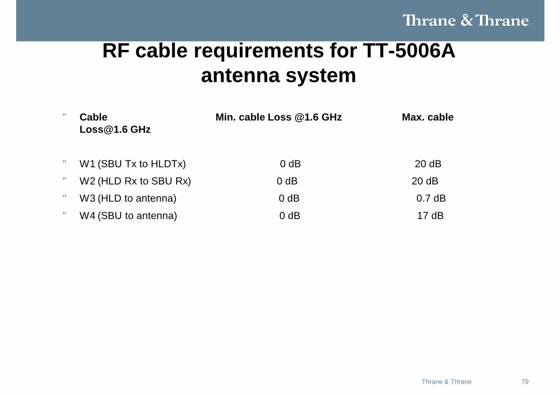
RF cable requirements for TT-5006A antenna system
• Cable Min. cable Loss @1.6 GHz Max. cable [email protected] GHz
• W1 (SBU Tx to HLDTx) 0 dB 20 dB
• W2 (HLD Rx to SBU Rx) 0 dB 20 dB
• W3 (HLD to antenna) 0 dB 0.7 dB
• W4 (SBU to antenna) 0 dB 17 dB
80Thrane & Thrane
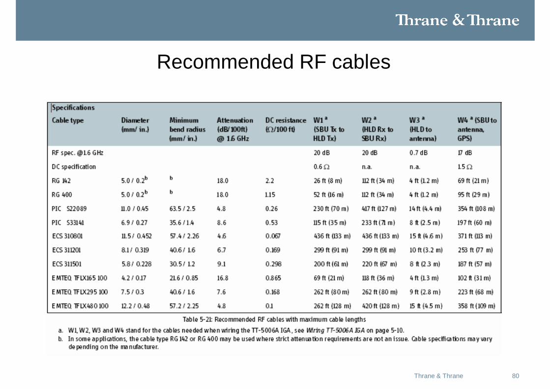
Recommended RF cables
81Thrane & Thrane
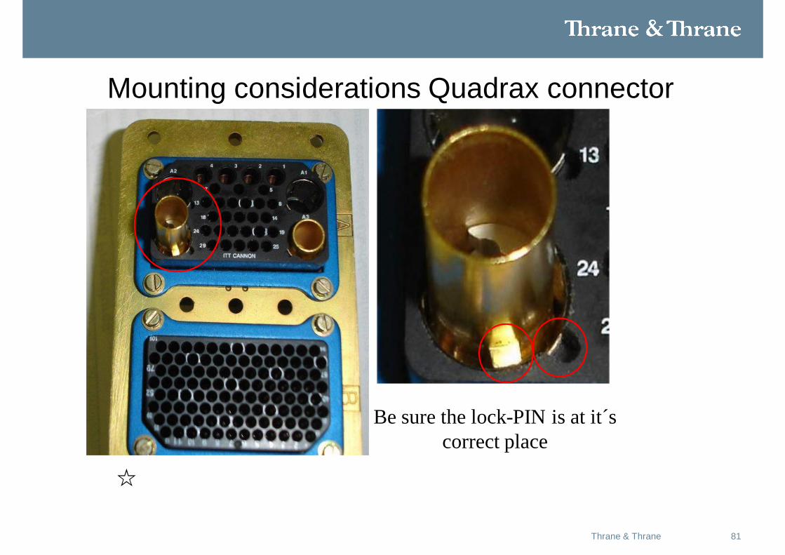
Mounting considerations Quadrax connector
Be sure the lock-PIN is at it´s correct place
82Thrane & Thrane
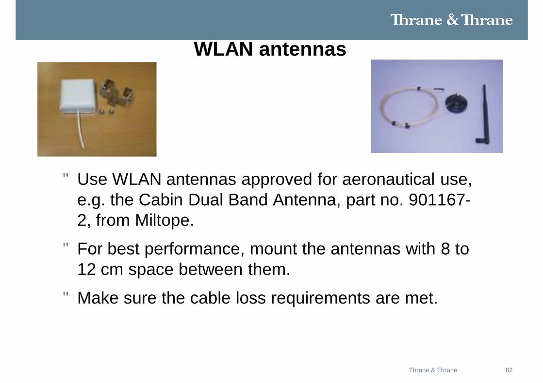
WLAN antennas
• Use WLAN antennas approved for aeronautical use, e.g. the Cabin Dual Band Antenna, part no. 901167-2, from Miltope.
• For best performance, mount the antennas with 8 to 12 cm space between them.
• Make sure the cable loss requirements are met.
83Thrane & Thrane
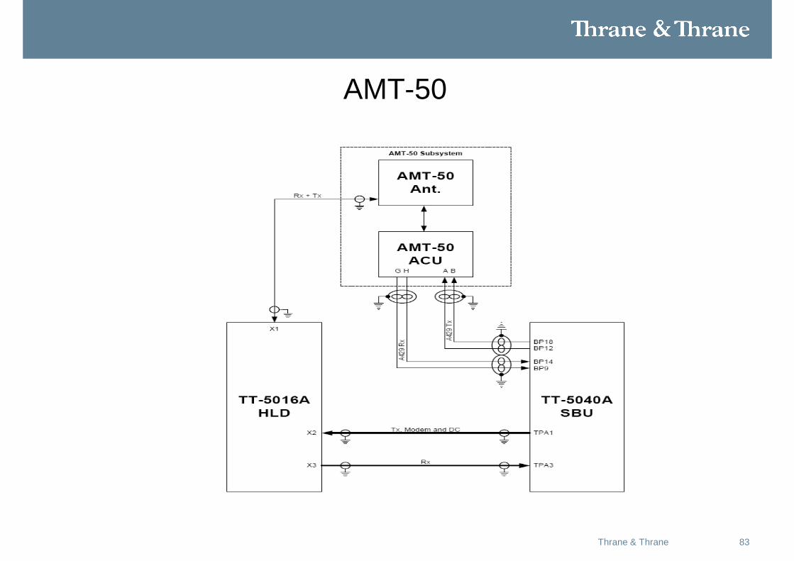
AMT-50
84Thrane & Thrane
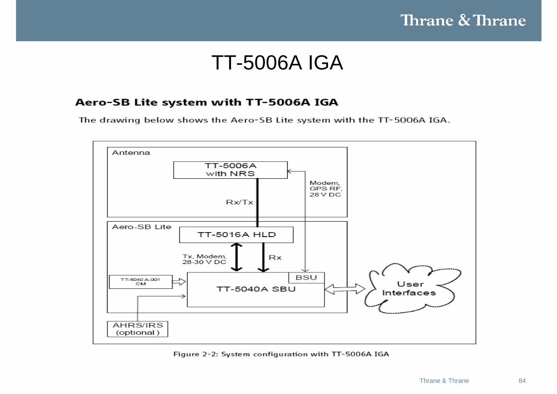
TT-5006A IGA
85Thrane & Thrane
AHRS/IRS
86Thrane & Thrane
ARINC 429
• The SBU has two ARINC 429 input interfaces for high speed IRS #1 and IRS #2 or high or low speed AHRS #1 and AHRS #2.
• If AHRS is used, a GPS antenna must also be connect
• See IM page 5-18
87Thrane & Thrane
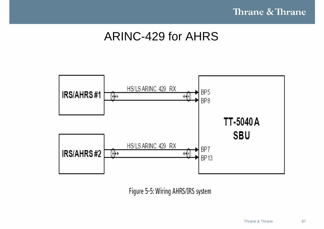
ARINC-429 for AHRS
88Thrane & Thrane
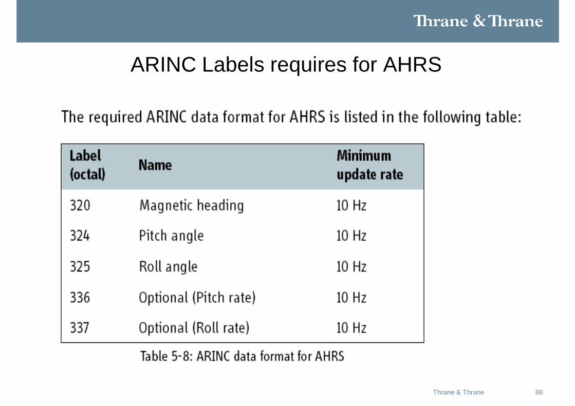
ARINC Labels requires for AHRS
89Thrane & Thrane
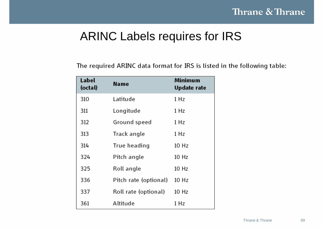
ARINC Labels requires for IRS
90Thrane & Thrane
IRS/AHRS Configuration
• When the system is configured with the web interface, the Configuration Module will contain the information of:
• • IRS or AHRS is installed.
• • IRS/AHRS # 1 or #2 or both are installed.
• • ARINC 429 Speed (High or Low).
• If IRS is used, the antenna positioning data is computed from the IRS data alone.
• If AHRS is used, the GPS must provide the SBU with 3D ECEF position and speed.
91Thrane & Thrane
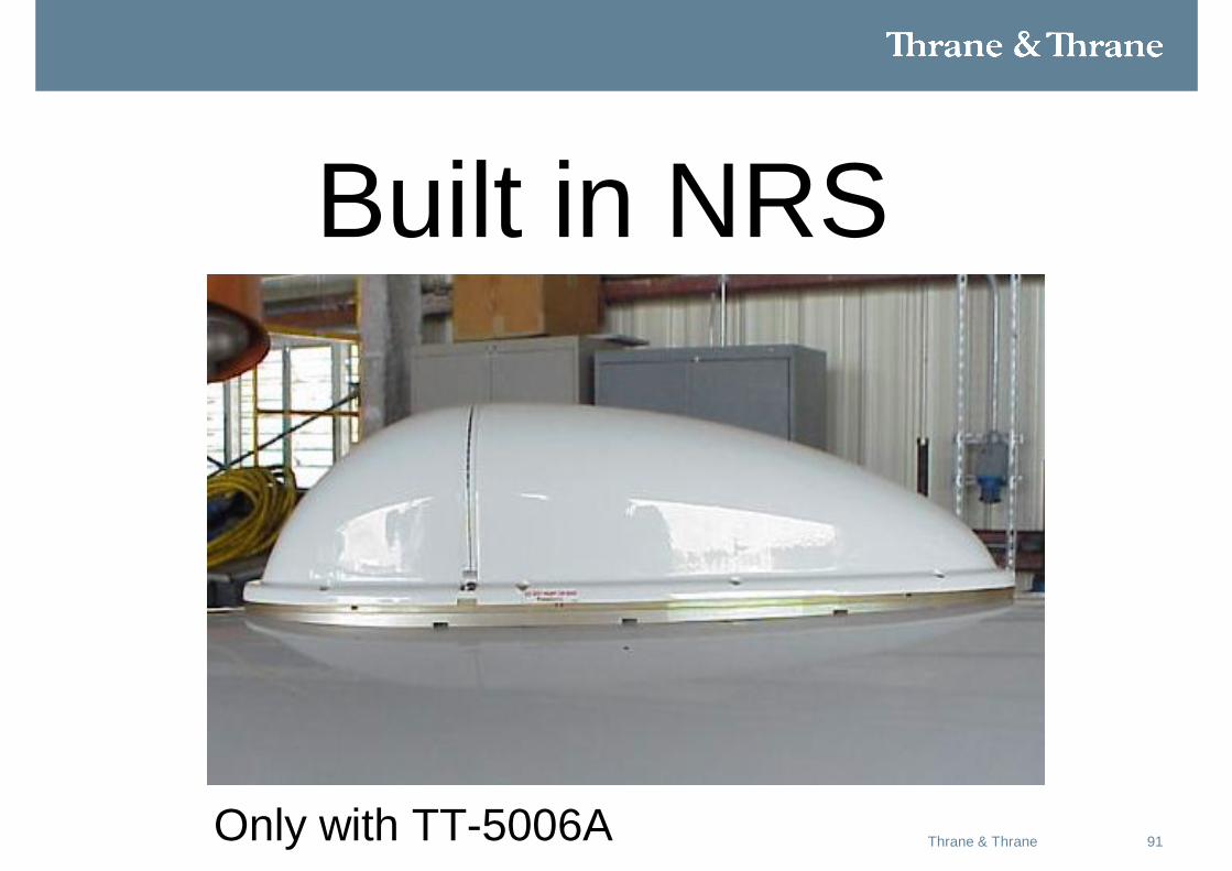
Built in NRS
Only with TT-5006A
92Thrane & Thrane
For a system with a TT-5006A IGA in the installation, you can use Built in NRS if IRS or AHRS is not available.
93Thrane & Thrane
Magnetic environment
• The TT-5006A IGA contains sensitive Magnetometers. These can be adversely influenced by ferrous materials, magnets or large currents in cables close to the antenna. Therefore you must obey the following mounting considerations:
• • Do not mount speakers or other equipment containing a magnet within 18 inches (48 cm) of this satcom antenna. If this cannot be avoided, install shielded speakers.
• • Avoid mounting close to strong magnetic fields from the aircraft’s power wiring.
• • Use non-magnetic screws and tools for mounting.
94Thrane & Thrane
Calibrating the NRS in the TT-5006A IGA
• For a system with a TT-5006A IGA you can use NRS if IRS/AHRS is not available.
• You must calibrate the integrated NRS. You mustrepeat the calibration procedure if you:
• Exchange the antenna or if you change the magnetic environment of the aircraft.
• The calibration data is stored in the CM.

95Thrane & Thrane
Magnetometer calibration procedure
• To calibrate the magnetometer do as follows:
• 1. Find a suitable location where the Aero-SB Lite system can obtain GPS
synchronization and where there is sufficient space for the aircraft to complete a 360° turn.
• 2. Power up all aircraft systems, including the engines. This is to create the aircraft magnetic environment as it would be during flight.
• 3. Wait until the GPS of the aircraft is operational.
• 4. Connect a PC with the web interface to the Maintenance connector of the SBU and enter the web interface.
96Thrane & Thrane
Magnetometer calibration procedure (Cont)
• 5. From the left navigation pane select SETTINGS > External systems.
• 6. Enter the section for magnetometer calibration.
• 7. Click the button Start Calibration to start the calibration procedure.
• 8. Start turning the aircraft in a 360° circle. Make sure that the turn rate is greater than 1° per second. The time span for one turn should be between 3 and 10 minutes.
• 9. When the turn is complete, click the button Stop calibration.
• 10. Click Apply to apply the new settings.
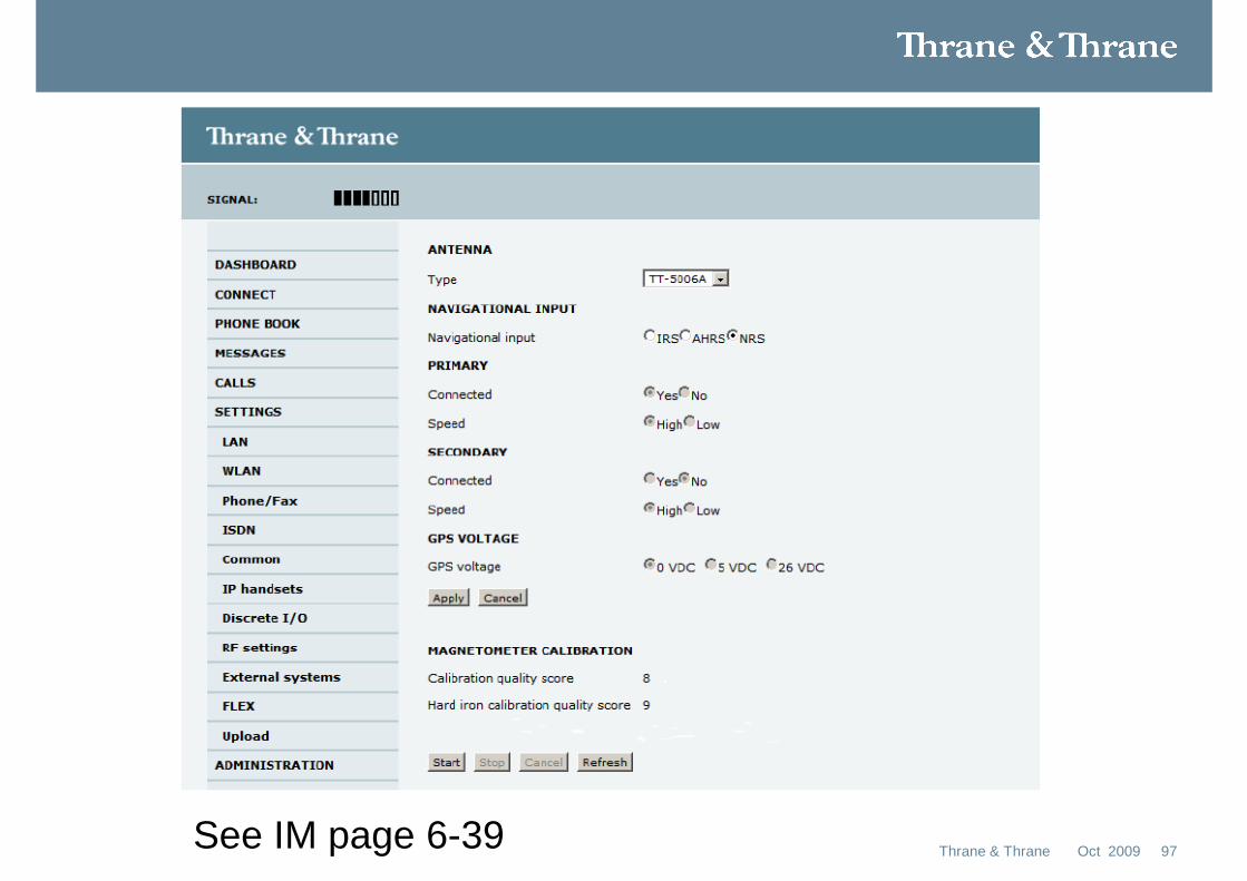
See IM page 6-39 97Oct 2009Thrane & Thrane

98Thrane & Thrane
Analyzing the magnetometer calibration score
• Having made the magnetometer calibration you must examine the quality of it.• Use the following table to examine the calibration score:

99Thrane & Thrane
See IM page A-1
Temp Specs
100Thrane & Thrane
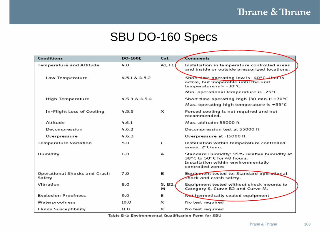
SBU DO-160 Specs
101Thrane & Thrane
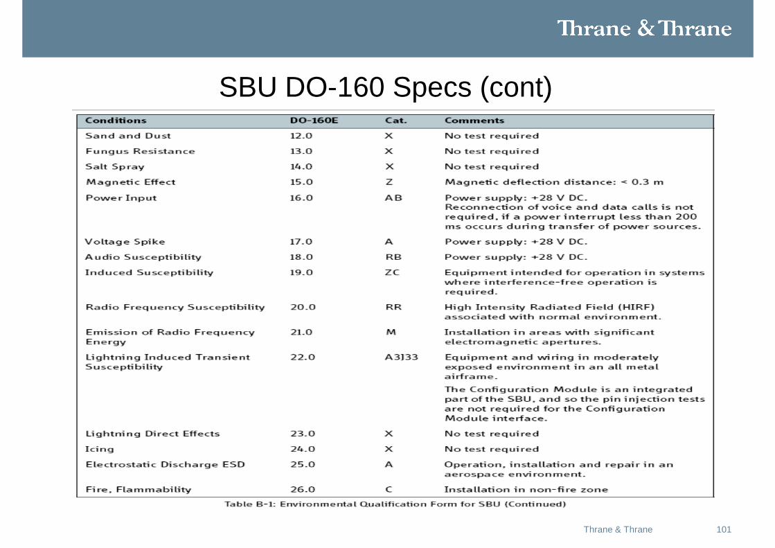
SBU DO-160 Specs (cont)
102Thrane & Thrane
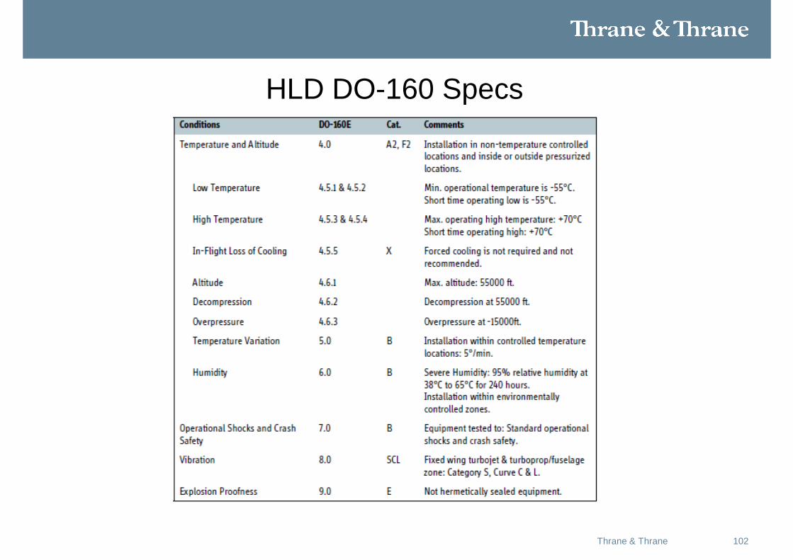
HLD DO-160 Specs
103Thrane & Thrane
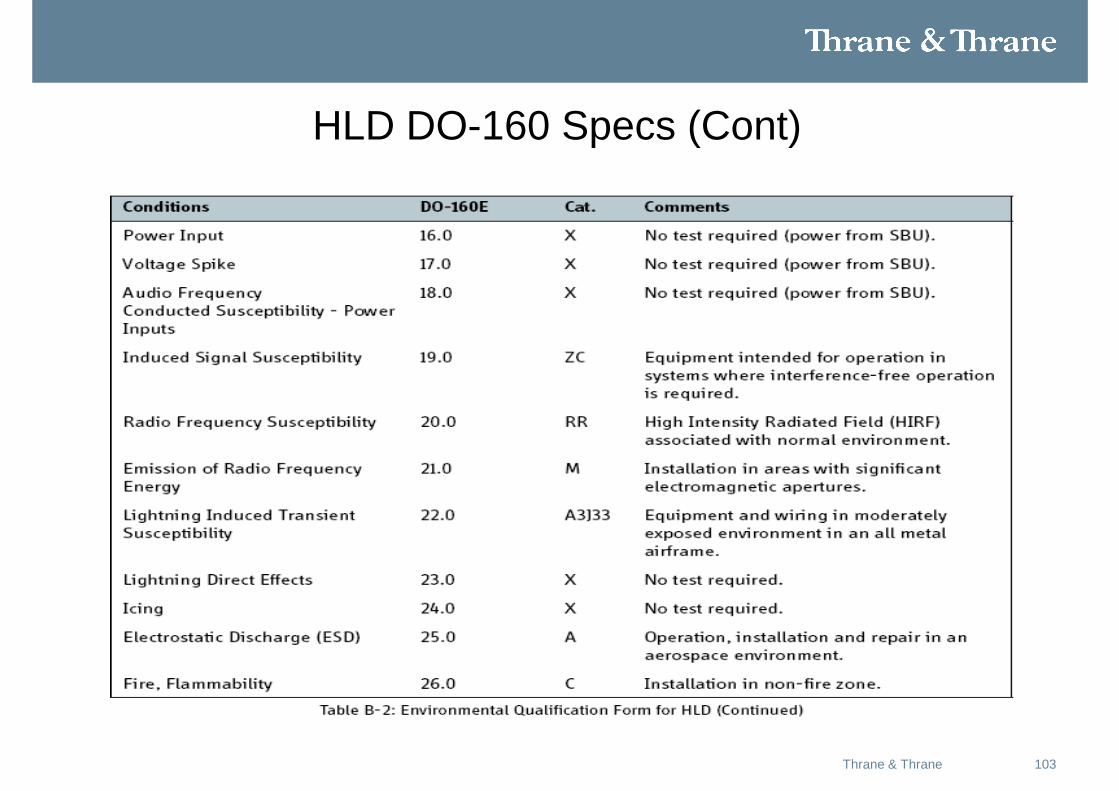
HLD DO-160 Specs (Cont)
104Thrane & Thrane
Configuration Module
105Thrane & Thrane
Purpose and function of the CM
• The CM is inserted in the back of the SBU and holds all system and user settings for easy replacement of the SBU.
• The CM contains a SIM card providing access to the Swift Broadband services.
• The CM is delivered with the SIM card installed.• Antenna calibration data is stored in the CM.• Configuration Data is stored in the CM.• The CM Must be removed and retained with the
aircraft in the event an SBU is returned for service.
106Thrane & Thrane
Handsets
107Thrane & Thrane
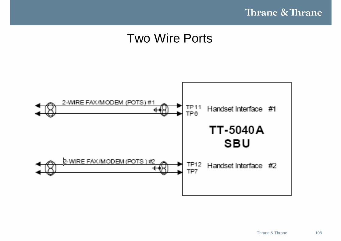
Description of 2-wire interfaces #1 and #2
• The SBU has two 2-wire Voice/Fax/Modem POTS interfaces connected to the internal PBX.
• The interfaces comply with 2-wire 600 Ω standard US DTMF telephones.
• The 2-wire interfaces are not galvanically isolated from the aircraft frame.
• Galvanic isolation is required at the external 2-wire terminal.
• Two TT-5621B 2-Wire Handset phones can be connected in parallel on each interface.
108Thrane & Thrane
Two Wire Ports
109Thrane & Thrane
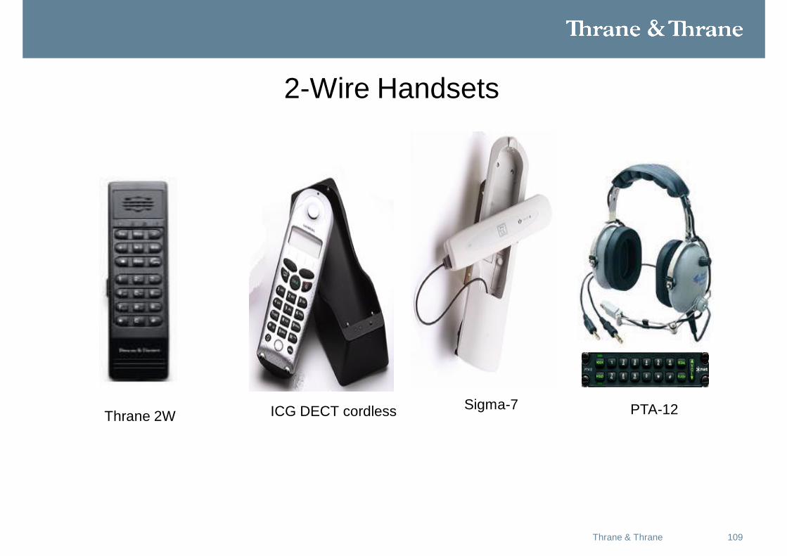
2-Wire Handsets
Thrane 2W ICG DECT cordless Sigma-7 PTA-12
11014-12-2010T&T SwiftBroadband Solutions
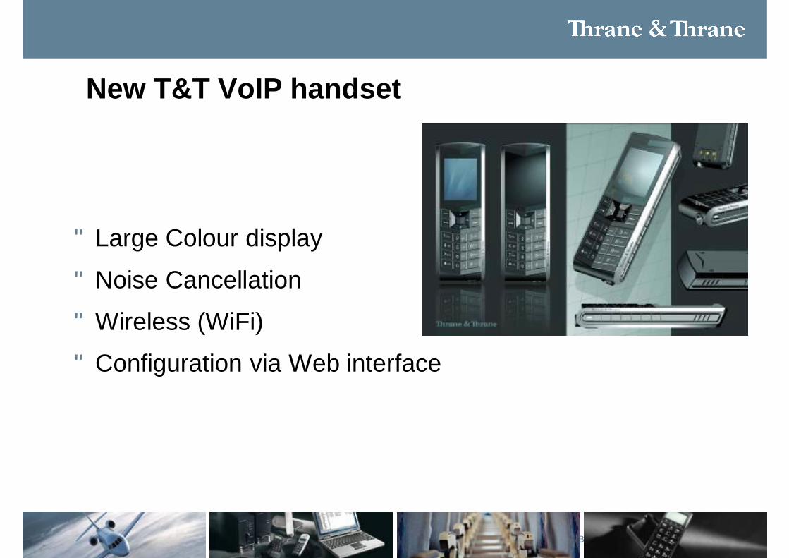
New T&T VoIP handset
• Large Colour display
• Noise Cancellation
• Wireless (WiFi)
• Configuration via Web interface
111Thrane & Thrane
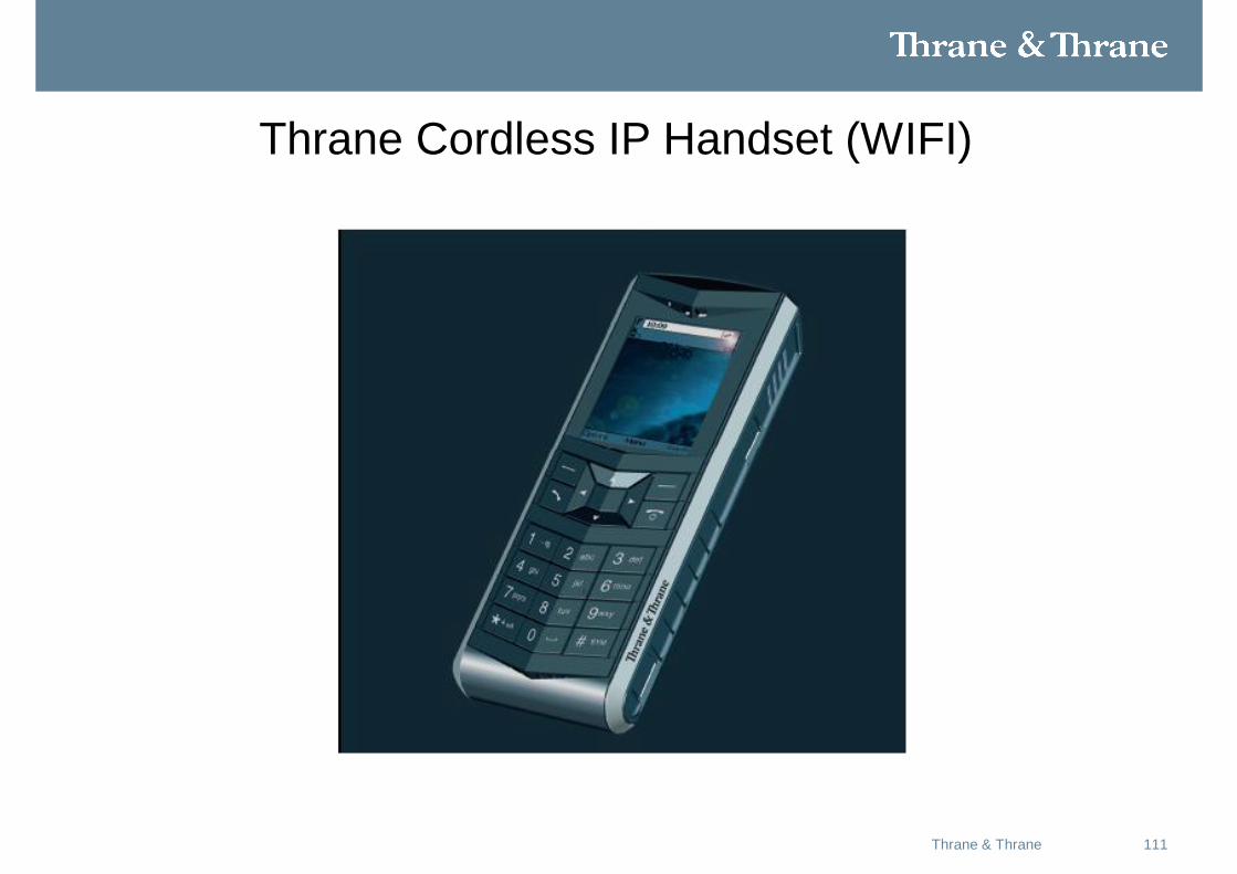
Thrane Cordless IP Handset (WIFI)
112Thrane & Thrane
External PBX
An external PBX can be connected to the SBU utilizing the two wire ports if more handsets are desired.
113Thrane & Thrane
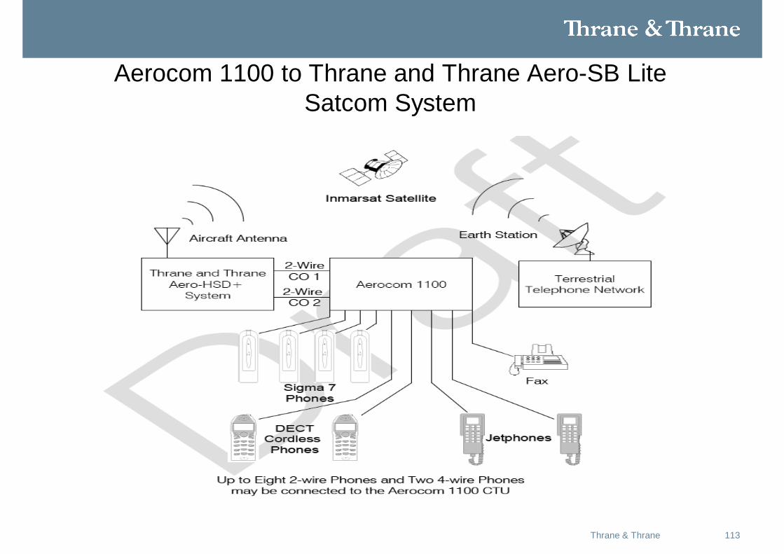
Aerocom 1100 to Thrane and Thrane Aero-SB Lite Satcom System
114Thrane & Thrane
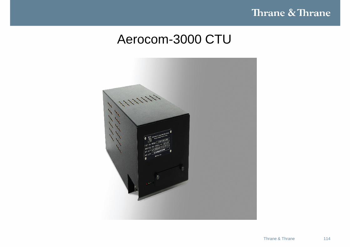
Aerocom-3000 CTU
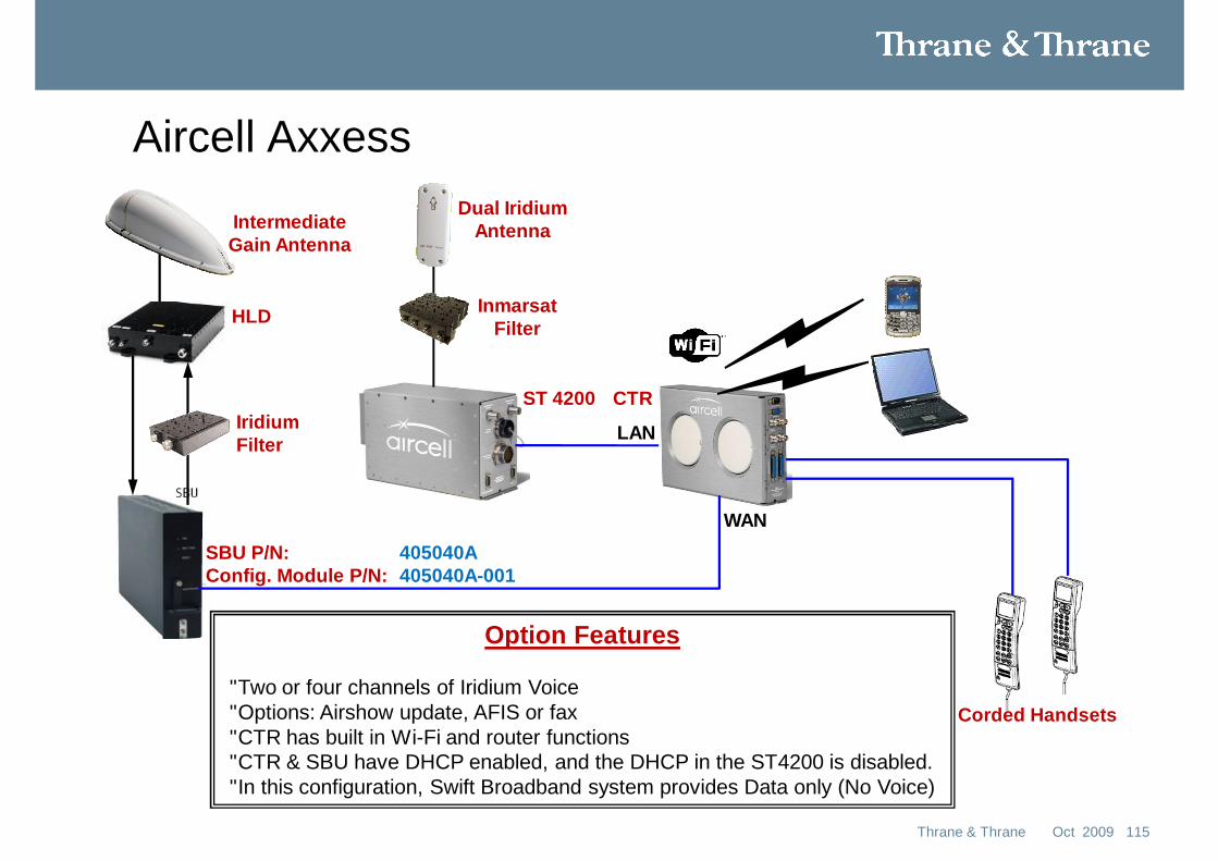
Aircell Axxess
115Oct 2009Thrane & Thrane
Option Features
• Two or four channels of Iridium Voice• Options: Airshow update, AFIS or fax• CTR has built in Wi-Fi and router functions• CTR & SBU have DHCP enabled, and the DHCP in the ST4200 is disabled.• In this configuration, Swift Broadband system provides Data only (No Voice)
SBU P/N: 405040AConfig. Module P/N: 405040A-001
IntermediateGain Antenna
Dual IridiumAntenna
InmarsatFilterHLD
IridiumFilter
ST 4200 CTR
Corded Handsets
LAN
WAN
116Thrane & Thrane
Iridium Band Reject Filter (IBRF)
117
Description of the problem
• Iridium is being jammed by Inmarsat Satcom systems active on the same aircraft.
• Two problems:1. Iridium does not have enough filtering to protect its receiver
from ”seeing” the Inmarsat transmit carrier. Iridium LNA saturates and the received signal degrades.
2. Inmarsat systems are transmitting unwanted (legal) out-of-band noise. Some of this noise falls in the Iridium band, and increases the noise seen by the Iridium receiver.
• Whichever problem is worse, dictates the lower limit for the distance between Inmarsat and Iridium antennas
118Thrane & Thrane
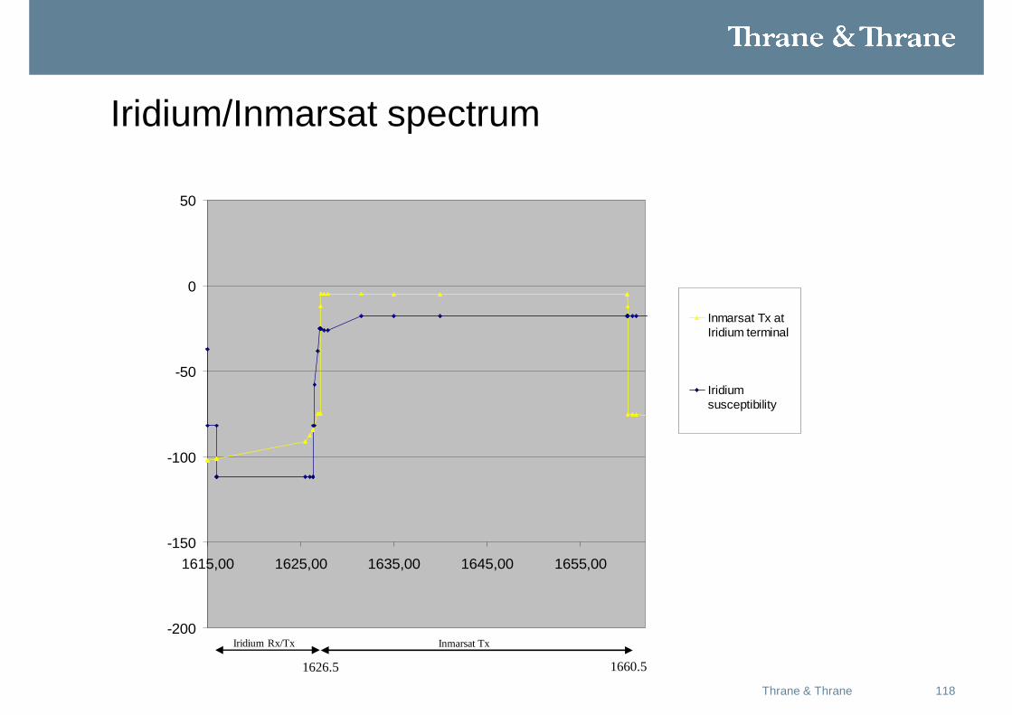
Iridium/Inmarsat spectrum
-200
-150
-100
-50
0
50
1615,00 1625,00 1635,00 1645,00 1655,00
Inmarsat Tx atIridium terminal
Iridiumsusceptibility
Iridium Rx/Tx Inmarsat Tx
1626.5 1660.5
119Thrane & Thrane
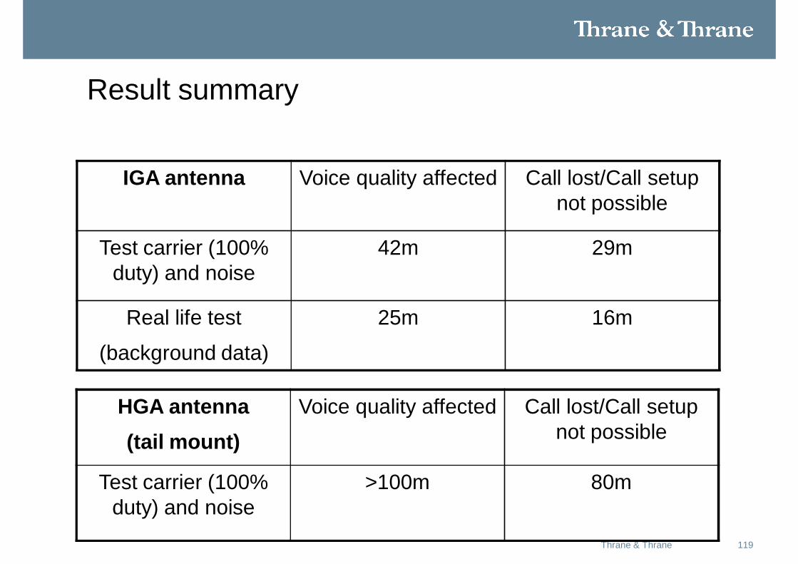
Result summary
IGA antenna Voice quality affected Call lost/Call setup not possible
Test carrier (100% duty) and noise
42m 29m
Real life test
(background data)
25m 16m
HGA antenna (tail mount)
Voice quality affected Call lost/Call setup not possible
Test carrier (100% duty) and noise
>100m 80m
120Thrane & Thrane
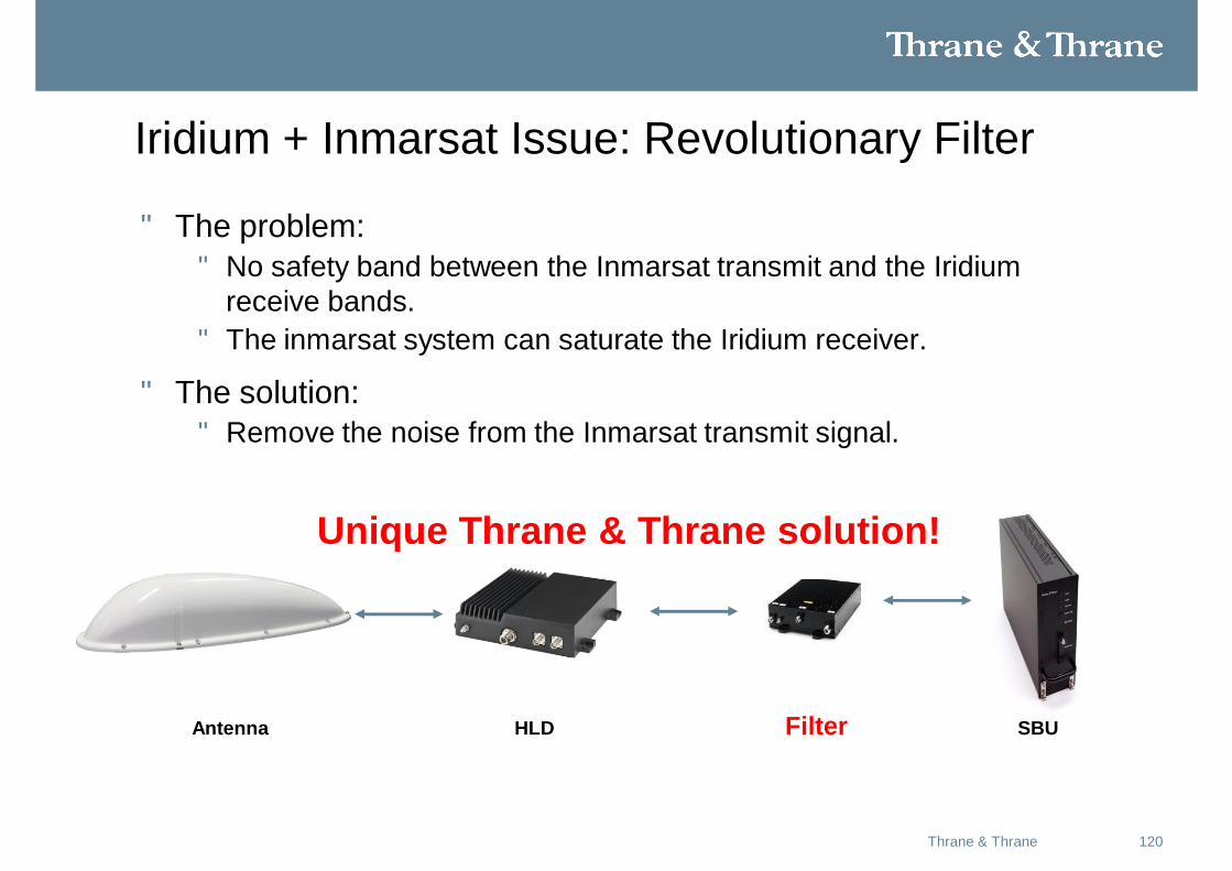
Iridium + Inmarsat Issue: Revolutionary Filter
• The problem: • No safety band between the Inmarsat transmit and the Iridium
receive bands.• The inmarsat system can saturate the Iridium receiver.
• The solution:• Remove the noise from the Inmarsat transmit signal.
Antenna HLD Filter SBU
Unique Thrane & Thrane solution!
121Thrane & Thrane
Conclusion
• Noise problem is a little bit worse than “carrier” problem.
• To ensure good Iridium performance, two filters are required.• A SATCOM filter on the Iridum terminal• An Iridium filter in the Inmarsat system
• Filters are required for IGA and HGA installations.
122May 2008Thrane & Thrane
Aero-SB Lite Configuration & use
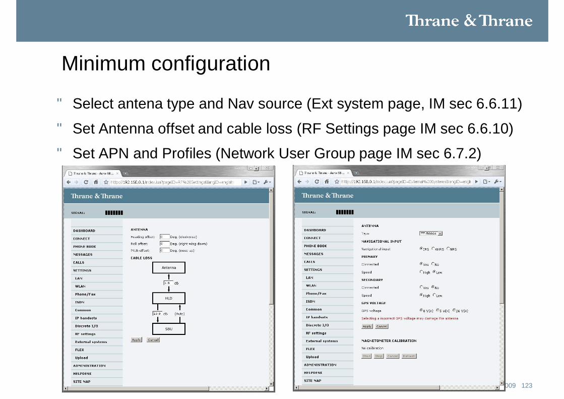
Minimum configuration
• Select antena type and Nav source (Ext system page, IM sec 6.6.11)
• Set Antenna offset and cable loss (RF Settings page IM sec 6.6.10)
• Set APN and Profiles (Network User Group page IM sec 6.7.2)
123Oct 2009Thrane & Thrane
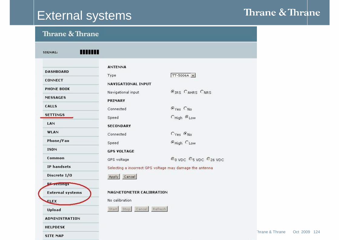
External systems
124Oct 2009Thrane & Thrane
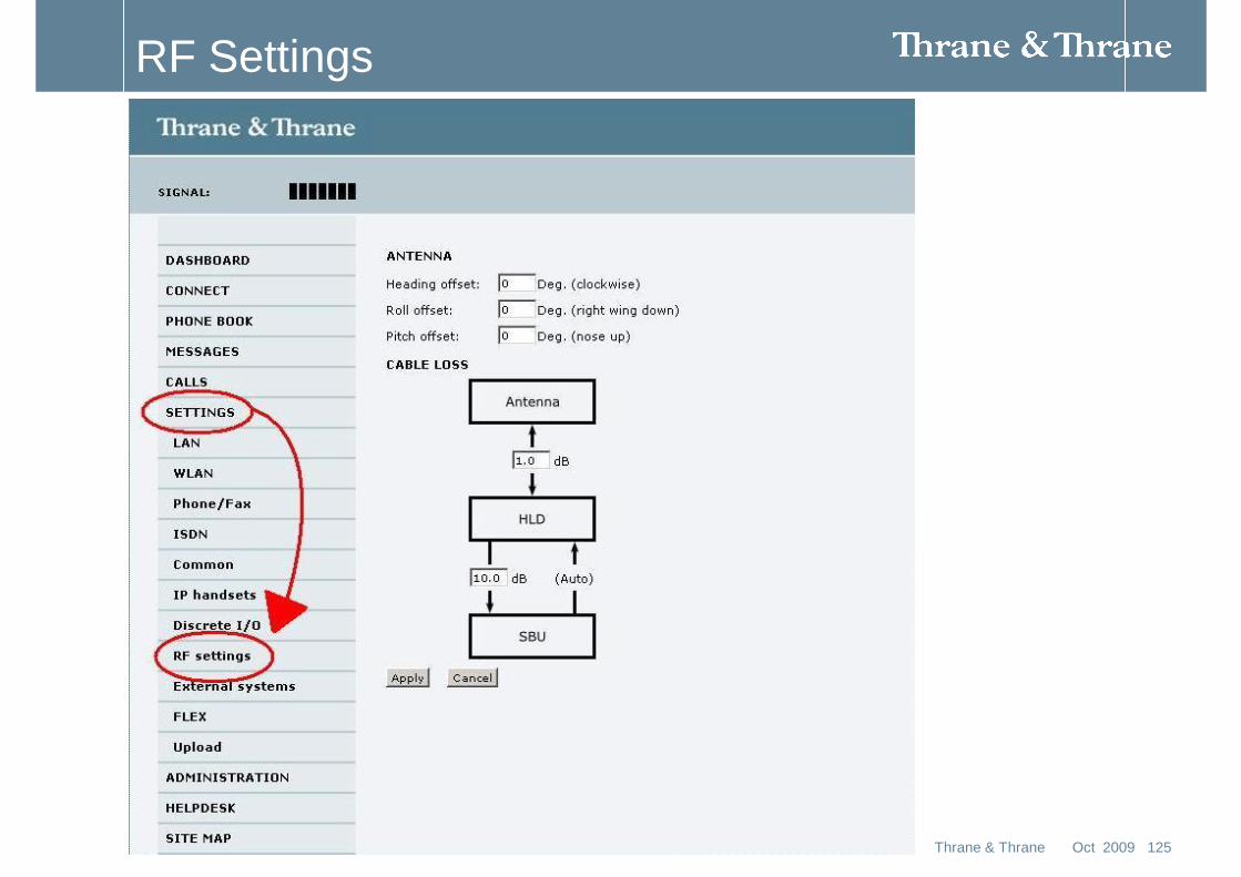
RF Settings
125Oct 2009Thrane & Thrane

Network User Group
126Oct 2009Thrane & Thrane
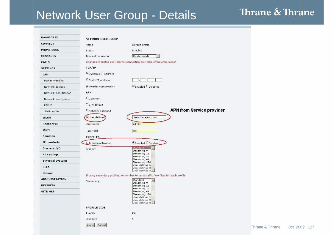
Network User Group - Details
127Oct 2009Thrane & Thrane
128Thrane & Thrane
The web interface
• What is the web interface?• The web interface is built into the terminal, and is
used for operating, setting up and configuring the system.
• You can access the web interface from a computer with a standard Internet browser.
• Internet Explorer 6.0, Mozilla Firefox 1.0 and Apple Safari 2.0 were tested successfully with the web interface. You may be able to use other browser versions as well.
129Thrane & Thrane
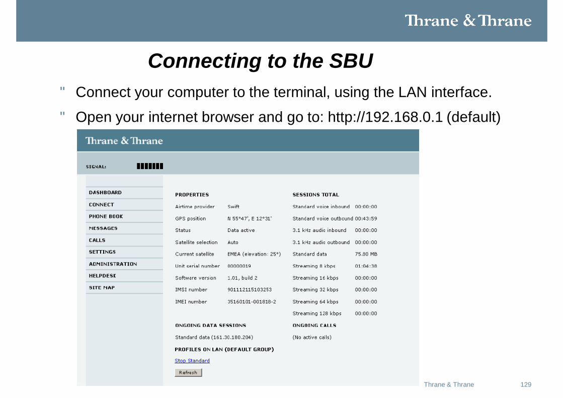
Connecting to the SBU • Connect your computer to the terminal, using the LAN interface.
• Open your internet browser and go to: http://192.168.0.1 (default)
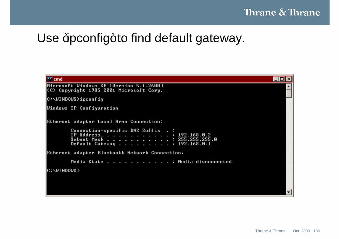
Use ”ipconfig” to find default gateway.
130Oct 2009Thrane & Thrane
131Thrane & Thrane
Browser settings
• If you are connecting your computer using the LAN interface, the Proxy server settings in your browser must be disabled before accessing the web interface.
• Most browsers support disabling of the Proxy server settings for one specific IP address, so you can disable Proxy server settings for the web interface only, if you wish.
• Consult your browser help for information.
• To disable the use of a Proxy server completely, do as follows:
132Thrane & Thrane
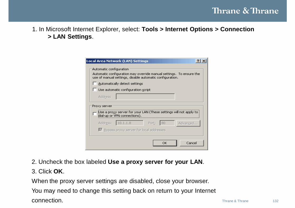
1. In Microsoft Internet Explorer, select: Tools > Internet Options > Connection> LAN Settings.
2. Uncheck the box labeled Use a proxy server for your LAN.3. Click OK.When the proxy server settings are disabled, close your browser.You may need to change this setting back on return to your Internetconnection.
133Thrane & Thrane
Changing the IP address
• If the IP address is changed and you do not have the new address, You can temporarily set the IP address to the default value by:
• Pressing the Reset button next to the Ethernet jack under the front connector panel of the terminal. You can then access the web interface and change the IP address.
• Note that if you do not change the IP address, the default IP address will only be valid until the terminal is powered off. Then the terminal returns to the IP address from before the Reset button was pressed.
134Thrane & Thrane
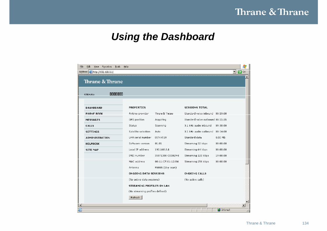
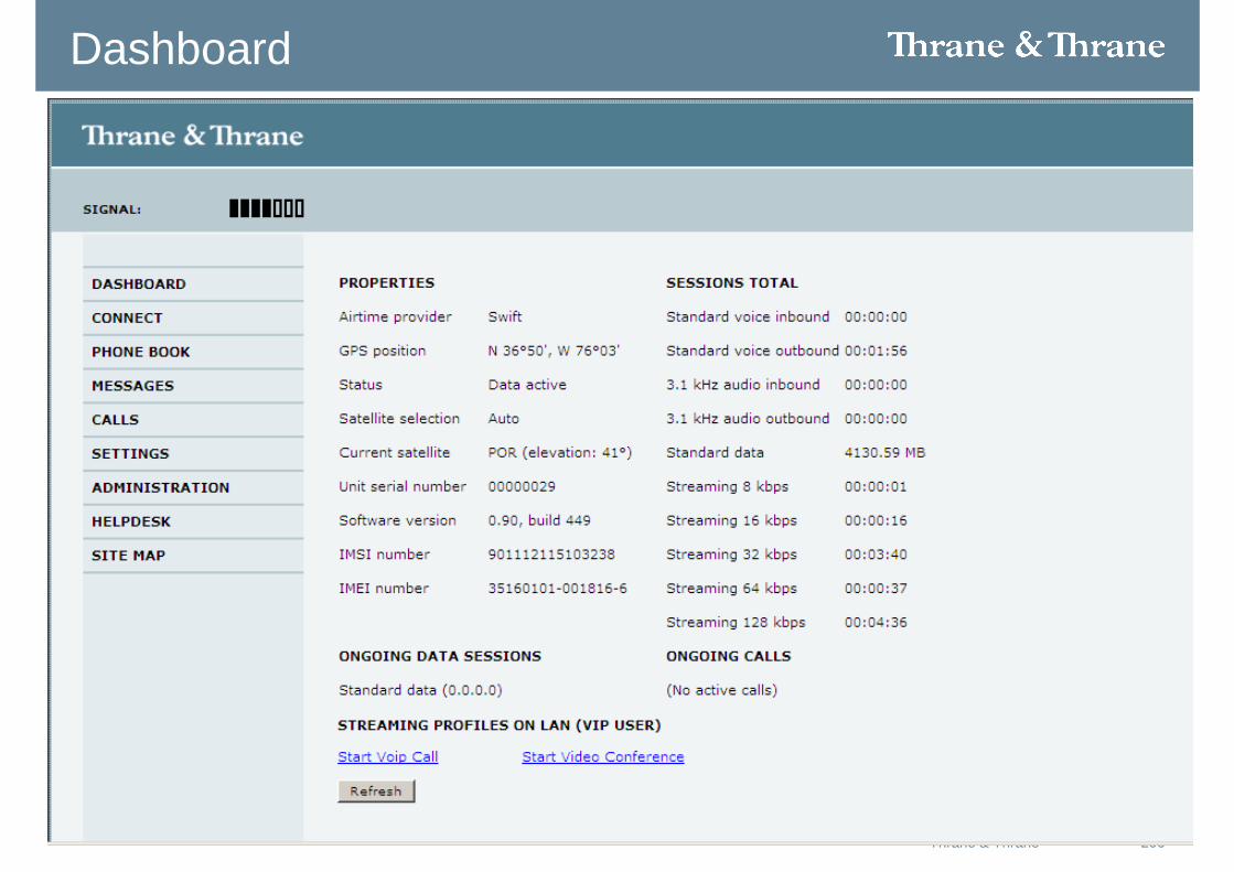
Using the Dashboard
135Thrane & Thrane
Properties
The PROPERTIES section of the DASHBOARD shows the following information:
• Airtime provider. The name of your Airtime Provider.
• GPS position. The GPS position of your system.
• Status. The status of the terminal and antenna.
Examples of status information are: Scanning, Ready and Data active.
• Satellite selection. The satellite selected for logon.
• Unit serial number. The serial number of the terminal.
136Thrane & Thrane
Properties cont.
• Software version. The version of the software embedded in the terminal.
• Local IP address. The local IP address of the terminal. This is the IP address
used to access the terminal from a device connected to the terminal.
• IMEI number. The IMEI number (International Mobile Equipment Identity) of the terminal. This is a unique number that identifies your terminal.
• MAC address for the LAN interface in the terminal.
• Antenna. The type of antenna connected to the terminal, and the status of the antenna.
137Thrane & Thrane
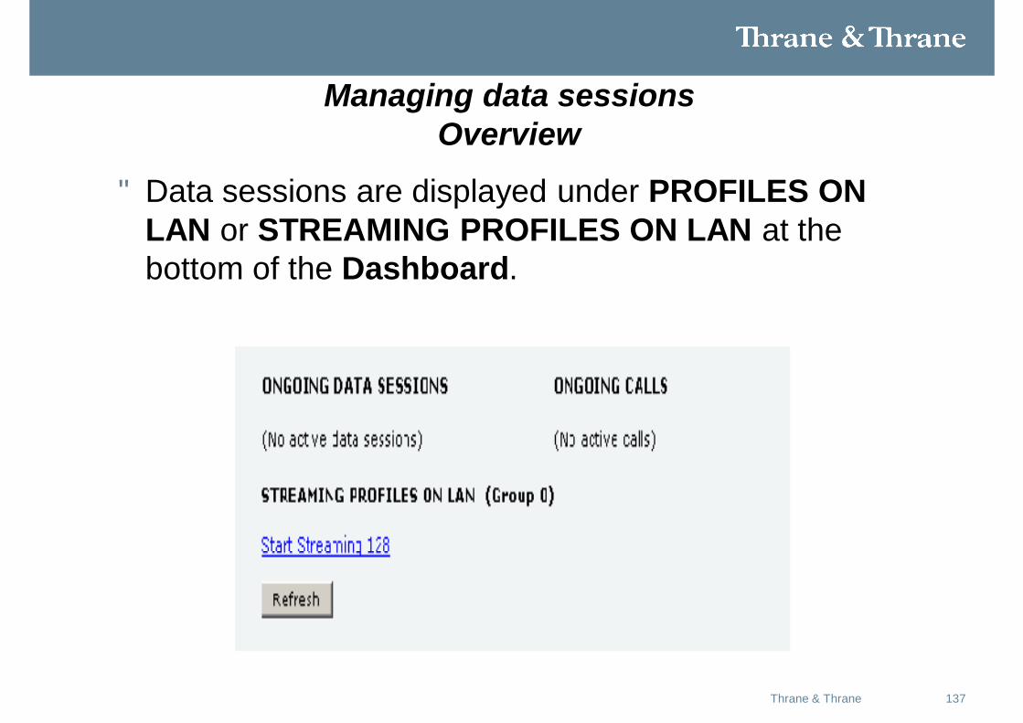
Managing data sessionsOverview
• Data sessions are displayed under PROFILES ON LAN or STREAMING PROFILES ON LAN at the bottom of the Dashboard.
138Thrane & Thrane
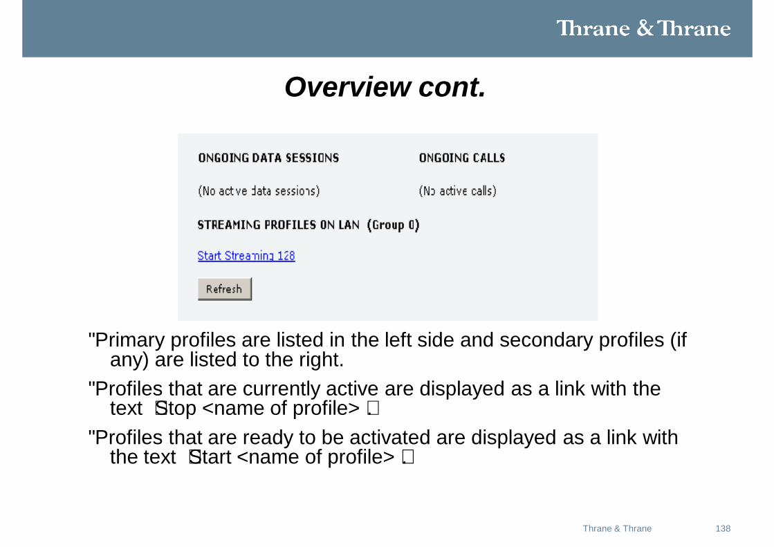
Overview cont.
• Primary profiles are listed in the left side and secondary profiles (if any) are listed to the right.
• Profiles that are currently active are displayed as a link with the text “Stop <name of profile>”.
• Profiles that are ready to be activated are displayed as a link with the text “Start <name of profile>”.
139Thrane & Thrane
Start/stop a Streaming session on the LAN interface
• Note Before starting a Streaming session, make sure you have set up a Streaming profile for your user group in the SETTINGS > LAN > Network user groups page.
• Note that if another primary profile is active you must stop it before you can start your new profile!
• Important If you have selected a Streaming connection as your primary profile, the LAN interface will be running a Streaming connection until you stop it or disconnect the interface. However, if you select one or more secondary profiles, you can set up your traffic flow filter so that it will only use the Streaming profile for certain types of traffic.
140Thrane & Thrane
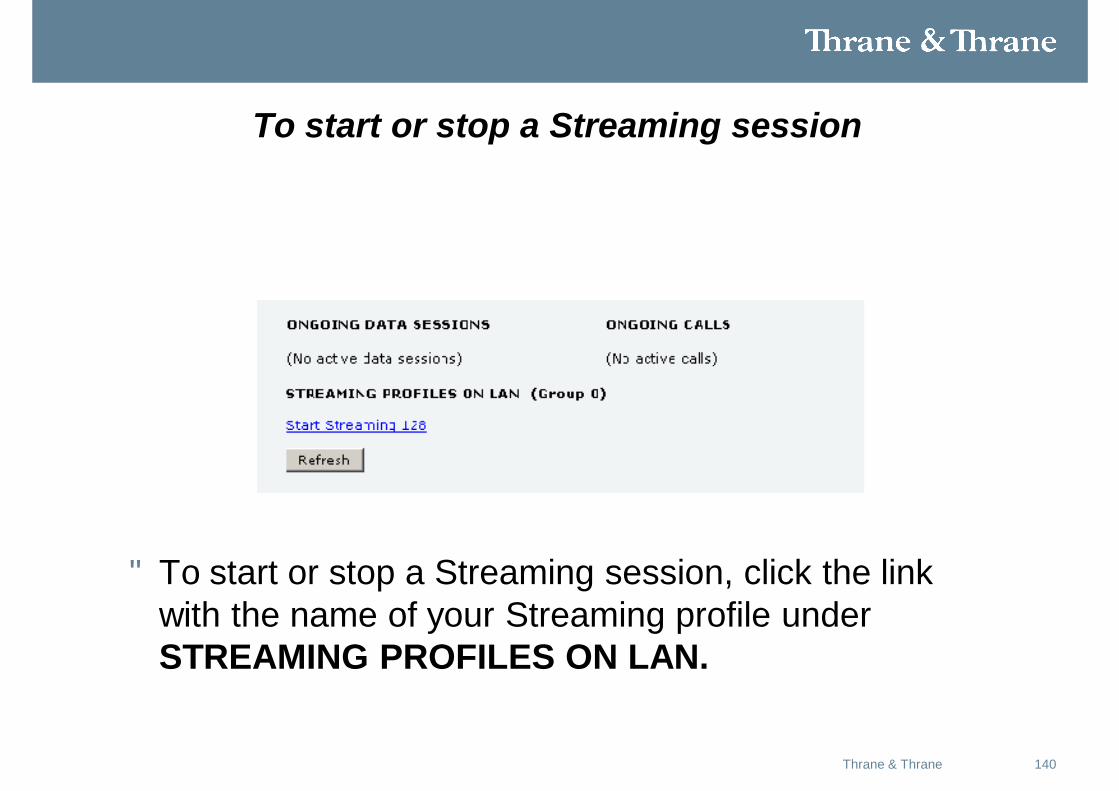
To start or stop a Streaming session
• To start or stop a Streaming session, click the link with the name of your Streaming profile under STREAMING PROFILES ON LAN.
141Thrane & Thrane
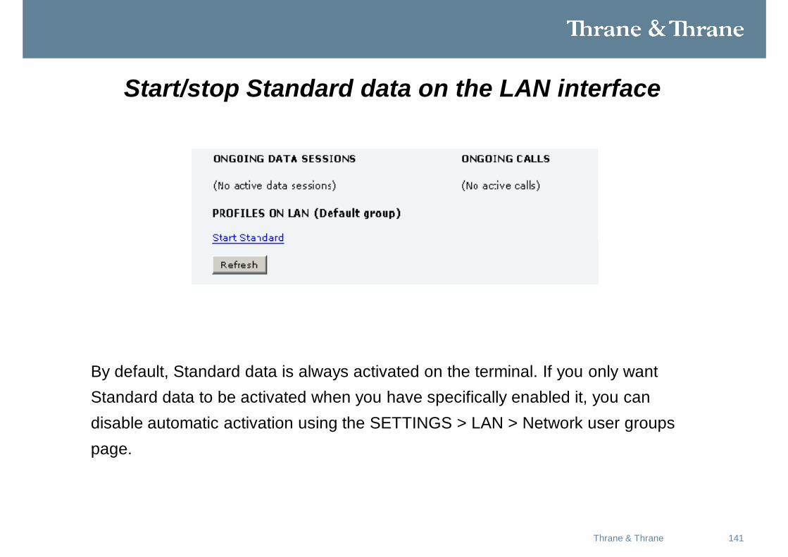
Start/stop Standard data on the LAN interface
By default, Standard data is always activated on the terminal. If you only wantStandard data to be activated when you have specifically enabled it, you candisable automatic activation using the SETTINGS > LAN > Network user groupspage.
142Thrane & Thrane
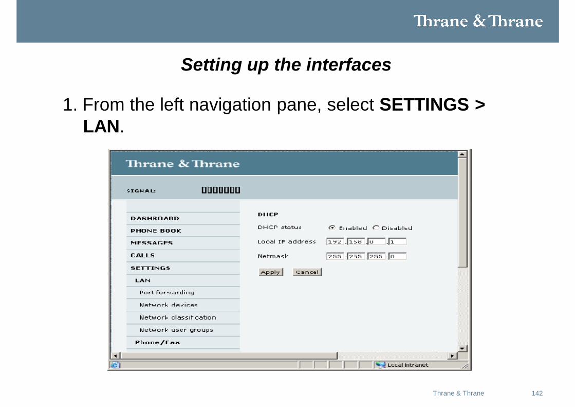
Setting up the interfaces
1. From the left navigation pane, select SETTINGS > LAN.
143Thrane & Thrane
Setting up the interfaces Cont.
2. At DHCP status, select Enabled (recommended), or Disabled.
• If you select Enabled, the terminal assigns dynamic IP addresses to
devices connected to the terminal.
• If you select Disabled, you need to set up a static IP address in the
connected device.
3. Type in the Local IP address and the Netmask.
The Local IP address is the IP address used for accessing the web
interface.
4. Click Apply.
144Thrane & Thrane
Port forwarding
• Port forwarding enables you to set up a server connected to the terminal while the terminal is in Router mode. Without port forwarding it would not be possible to contact the server from the internet.
• The following example shows how to allow internet access to a mail server (smtp) connected to the terminal.
• The mail server in this example has the IP address 192.168.0.100.
145Thrane & Thrane
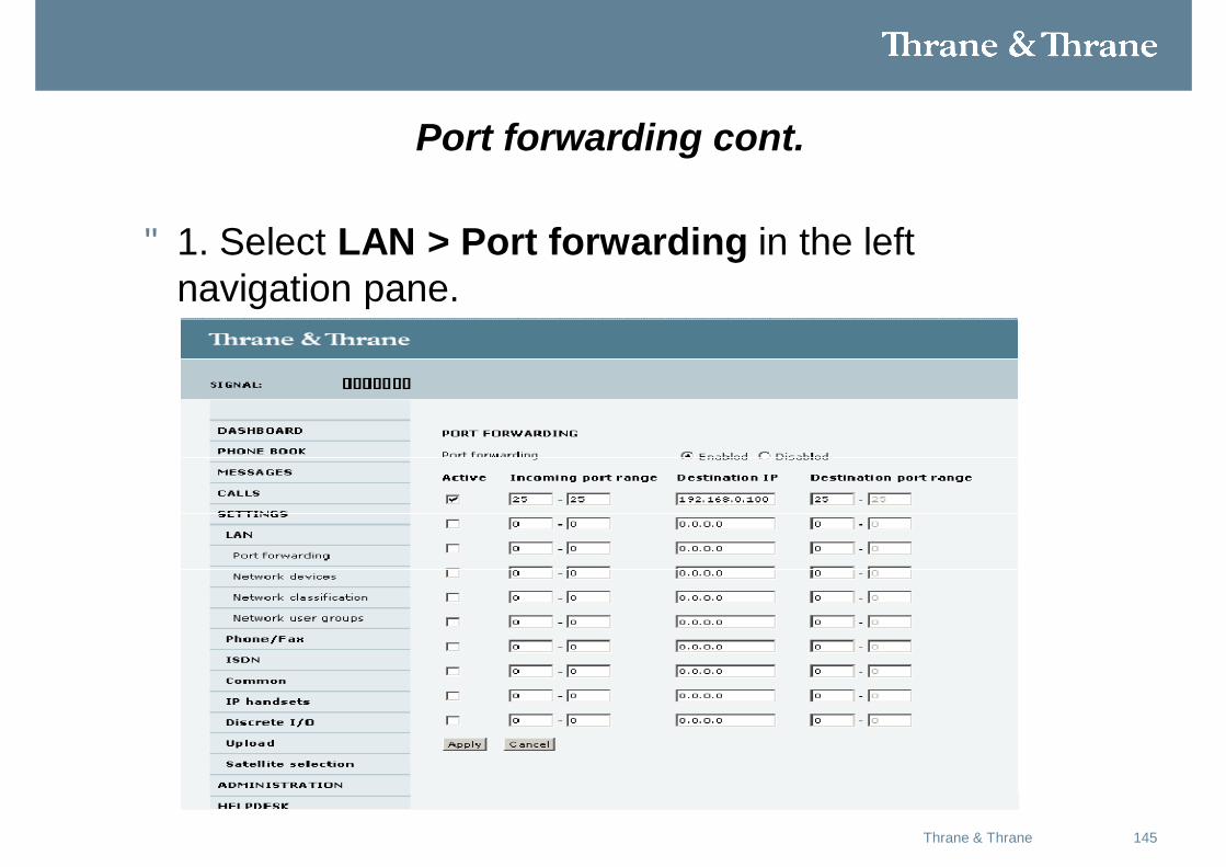
Port forwarding cont.
• 1. Select LAN > Port forwarding in the left navigation pane.
146Thrane & Thrane
Port forwarding cont.
2. Select Enabled to generally enable port forwarding.
3. Type in the Incoming port range.
4. Type in the Destination IP address, which in this example is the IP address of the mail server: 192.168.0.100.
5. Type in the Destination port range.
6. Repeat step 3 to step 5 to set up port forwarding to additional servers.
7. In the Active column, select which ports should have port forwarding
activated.
8. Click Apply.
• You can now access the mail server from the Internet, using the external IP
address of the terminal.
147Thrane & Thrane
Configuring the Phone/Fax interface
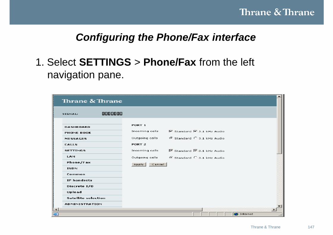
1. Select SETTINGS > Phone/Fax from the left navigation pane.
148Thrane & Thrane
Configuring the Phone/Fax interface cont.
2. For each Phone/Fax port, set the call type for incoming and outgoing calls.
• For Incoming calls, you can check Standard or 3.1 kHz Audio or both.
*If you check both, any device connected to the Phone/Fax interface will
react (ring) on incoming calls.
*If you select e.g. Standard, the Phone/Fax interface will only react on
calls made to the Standard phone number.
• For Outgoing calls, you can select either Standard or 3.1 kHz Audio. The
selected type will be used by default, if possible, for any outgoing call.
Note, however, that fax machines and modems must use 3.1 kHz Audio.
149Thrane & Thrane
Configuring the Phone/Fax interface cont.
• Note You can override the default setting for outgoing calls by dialing
• 1* (force the call to Standard) or
• 2* (force the call to 3.1 kHz Audio) before the number.
3. Click Apply.
150Thrane & Thrane
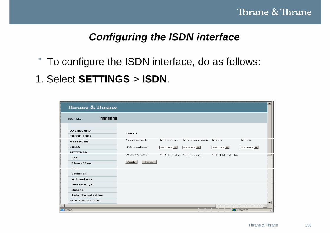
Configuring the ISDN interface
• To configure the ISDN interface, do as follows:
1. Select SETTINGS > ISDN.
151Thrane & Thrane
Configuring the ISDN interface cont.
2. Set the call type (s) for incoming calls.
• You can select Standard, 3.1 kHz Audio, UDI or RDI.
Note Connected devices will only receive incoming calls with the calltypes that are selected here.For example, if only Standard is selected, and a G4 fax call(using call type UDI) arrives, a fax connected to the ISDN portwill not receive the incoming call.
3. Set the MSN numbers that are to be assigned to each call type.Note that this setting only applies to the call type selected above the MSNnumber, and only if the connected device supports the call type used.
152Thrane & Thrane
Configuring the ISDN interface cont.
• Important If you set an MSN number to anything other than <None>,connected devices must be programmed with these MSN numbers.
4. Set the call type for outgoing calls.
• If you select Automatic, the call type will be determined by the calling
device.
• If you select Standard, all outgoing calls, except UDI/RDI, will use the
call type Standard. If you make a 3.1 kHz Audio call it will be converted
to a Standard call.
Outgoing UDI or RDI sessions will be not be influenced by this setting.
153Thrane & Thrane
Configuring the ISDN interface cont.
• If you select 3.1 kHz Audio, all outgoing calls, except UDI/RDI, will use
the call type 3.1 kHz Audio. If you make a Standard call it will be
converted to a 3.1 kHz Audio call. Outgoing UDI or RDI sessions will
not be influenced by this setting.
5. Click Apply.
Note You can override the call type setting for outgoing calls by
dialing one of the following prefixes before the number:
• 1* (force the call to Standard)
• 2* (force the call to 3.1 kHz Audio)
154Thrane & Thrane
Setting the common interface settings
The common APN (Access Point Name)The common APN setting is defined here and can be selected for each network user group. If you are using the same APN for many network user groups, it is easier to define it once, and then simply select it for the relevant user groups. Also, if you change the common APN at a later stage, it is automatically updated for all network user groups where the Common setting is selected.
155Thrane & Thrane
The common APN cont.
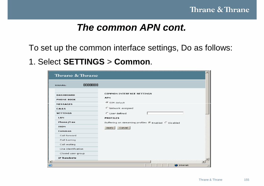
To set up the common interface settings, Do as follows:
1. Select SETTINGS > Common.
156Thrane & Thrane
The common APN cont.
2. Select the APN. You have the following options:
• SIM default. The APN is taken from the SIM card located inside of the configuration Module. This is the recommended option, unless you have special requirements.
• Network assigned. The APN is assigned from the network.
• User defined. Type in the APN. APNs are provided from the Airtime Provider.
157Thrane & Thrane
The common APN cont.
3. At Buffering on Streaming profiles, select Enabled or Disabled.
• If you select Enabled, your Streaming connection will be buffered. This
means that the transmission is slightly delayed in order to ensure a
precise and continuous data stream.
• If you select Disabled, your Streaming connection will not be buffered.
This means the data is delivered immediately, but may vary slightly in
transmission speed.
4. Click Apply.
158Thrane & Thrane
How to use the common APN
• When you configure the APN for your individual network user group, select:
Common to use the setting from this page.
• Where Common is selected in the individual groups, the setting will automatically be updated when the Common APN is changed.
159Thrane & Thrane
Setting up call servicesoverview
In the web interface you can set up the following supplementary services:• Call forwarding• Call barring• Call waiting• Line identification• Closed user groupNote that, depending on the network, some of these call service settings may prevent others from being activated. The settings apply for all connected devices using a circuit-switched service.
160Thrane & Thrane
Setting up the network user groups
• A network user group, in this context, is a group of network users sharing the same Quality of Service profile and network parameters.
• There are 11 configurable network user groups. For the Default user group.
• Certain settings are locked, to make sure there is always one functional user group available. For example, the Default user group does not allow you to select a Bridge mode connection.
Note The network user groups cannot be deleted. If you do not want to
use them, click Edit and select Disabled at Status in the NETWORKUSER GROUP field.
161Thrane & Thrane
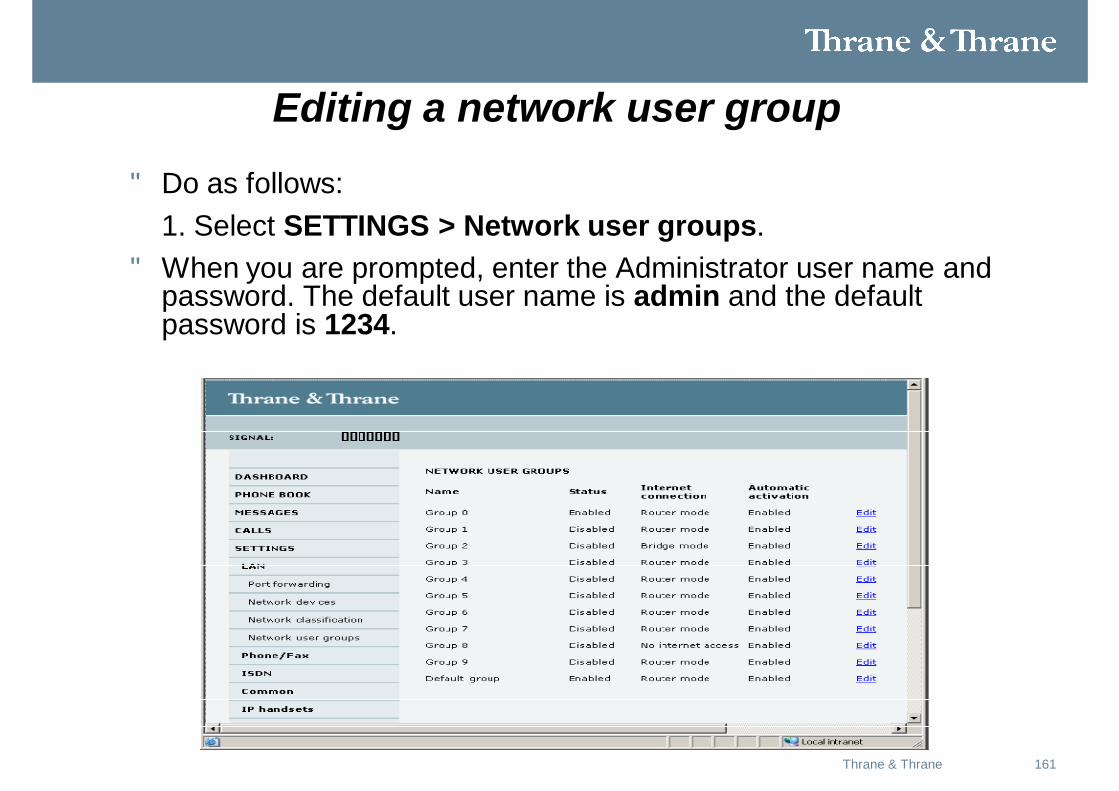
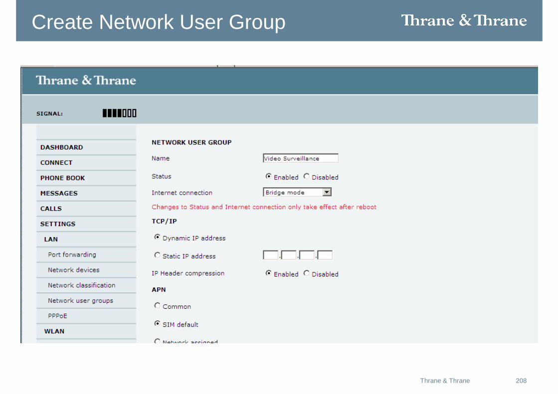
Editing a network user group
• Do as follows:1. Select SETTINGS > Network user groups.
• When you are prompted, enter the Administrator user name and password. The default user name is admin and the default password is 1234.
162Thrane & Thrane
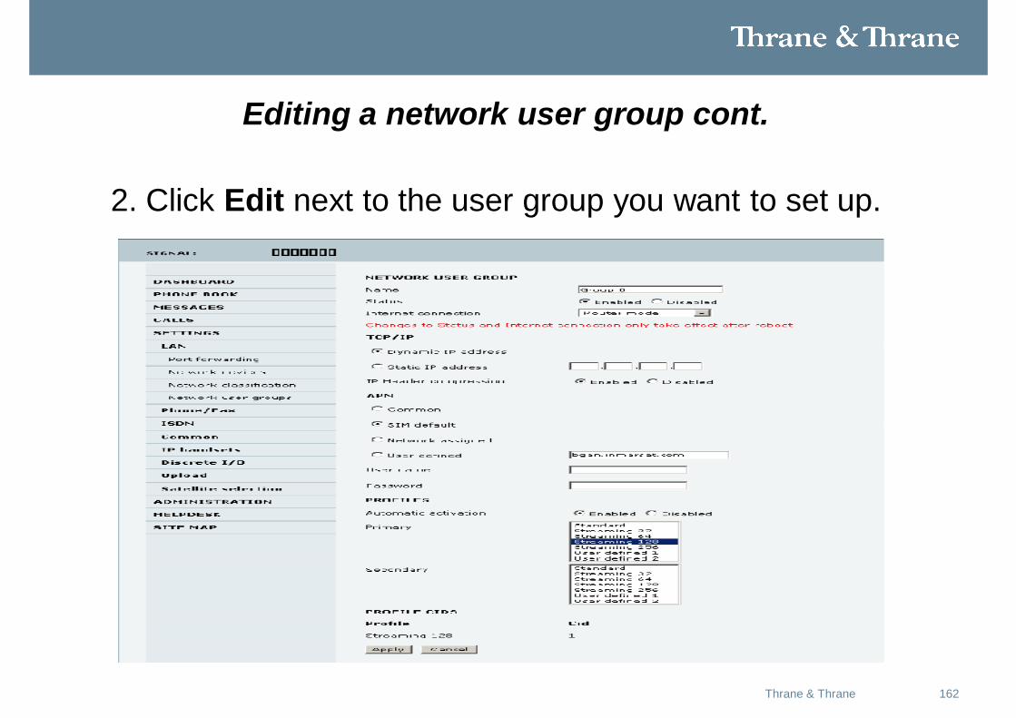
Editing a network user group cont.
2. Click Edit next to the user group you want to set up.
163Thrane & Thrane
Editing a network user group cont.
3. Type in a name for the group.4. Select Enabled or Disabled. 5. Select the type of Internet connection.
• Router mode means the connection will be shared with other users, and the NAT module of the terminal will make the necessary address translations. Use this mode if one or more computers are connected using the LAN interface, and the terminal should act as a router.• Bridge mode is an exclusive connection, with NAT disabled. Use this mode together with a network classification entry that selects a single computer. This mode is not available in the Default user group.• No internet access means no connection to the Internet is allowed. Usethis setting e.g. for IP handsets, where an Internet connection is notrequired. The external voice connection is still available; this settingonly affects communication over the Internet.
164Thrane & Thrane
Editing a network user group cont.
6. Select Dynamic IP address.
This is the IP address used externally on the satellite network.
If you want to use a static IP address, and your subscription allows it, you must still leave this setting at Dynamic. Then select SIM default in step 8 and type in the APN user name and password from your provider in step 9.
Your terminal will then use the static IP address set up for your SIM card.
Note Typing in a static IP address is currently not supported by the BGAN network.
165Thrane & Thrane
Editing a network user group cont.
7. Set IP Header compression to Enabled or Disabled.
8. Select the source of the APN (Access Point Name).
There are four options for setting the APN. Unless you have special
requirements, it is recommended to use the SIM default, or to set the
common APN to SIM default, and then select Common here. You have the
following options:
• Common. The APN is taken from the Common APN defined under
SETTINGS > Common. Refer to “Setting the common interface settings” in the previous slides.
166Thrane & Thrane
Editing a network user group cont.
• SIM default. The APN is taken from the SIM card. If you want to use a
static IP address on the external network, select this option either here
or in the Common setting.
• Network assigned. The APN is assigned from the network.
• User defined. Type in the APN. APNs are provided from the Airtime
Provider.
9. If your APN uses a password, type in the user name and password provided
from the Airtime Provider.
Note If you are going to use the static IP address from your SIM card, the user name and password are mandatory! See step 6 above.
167Thrane & Thrane
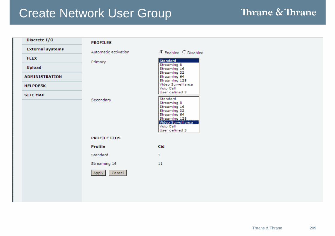
Editing a network user group cont.
10. At Automatic activation select whether the profile selected in the next step should be activated automatically or manually.
• Disabled means you can activate/deactivate the profile from the Dashboard.
• Enabled means the profile is activated automatically.
168Thrane & Thrane
Editing a network user group cont.
11. Select the Primary profile.
• Select a profile from the Primary scroll list. This profile is used by this network user group as a first choice, when possible.
• There are 4 predefined profiles in the AERO SBU:
• Standard, Streaming 32 kbps, Streaming 64 kbps and Streaming 128 kbps.
• Additionally, you can define your own custom profiles.
169Thrane & Thrane
Editing a network user group cont.
• Important: If you have selected a Streaming connection as your primary profile, the LAN interface will be running a
Streaming connection until you stop it or disconnect the
interface. However, if you select one or more secondary
profiles, you can set up your traffic flow filter so that it will
only use the Streaming profile for certain types of traffic.
• For further information on profiles and traffic flow filters, see Using profiles in the users manual.
170Thrane & Thrane
Editing a network user group cont.
12. Select the Secondary profile.
• To select more than one secondary profile, press and hold Ctrl or Shift while selecting.
• The Context Identifiers (CIDs) for the selected primary and secondary profiles are listed under Profile CIDs.
13. Click Apply.
171Thrane & Thrane
Managing network devices
• A network device, in this context, is an Ethernet hardware device, identified by a unique MAC address.
• When a network device with dynamic IP address is connected to the terminal, it is automatically listed in the Network devices list.
172Thrane & Thrane
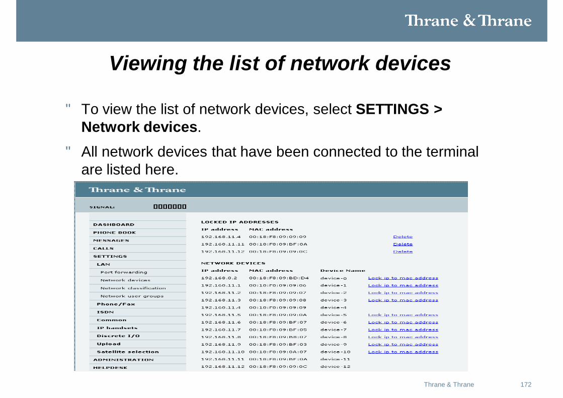
Viewing the list of network devices
• To view the list of network devices, select SETTINGS > Network devices.
• All network devices that have been connected to the terminal are listed here.
173Thrane & Thrane
Locking an IP address to a MAC address
• When the device is locked to an IP address, the terminal will always assign this IP address to the MAC address of this device (if DHCP is enabled and the Internet connection is not a Bridge mode connection).
• To lock a device to its current IP address, click the link next to the device. The device is then locked to the current IP address and added to the list of locked IP addresses at the top of the page.
• To unlock a device from the IP address, click Delete next to the device in the LOCKED IP ADDRESSES list.
174Thrane & Thrane
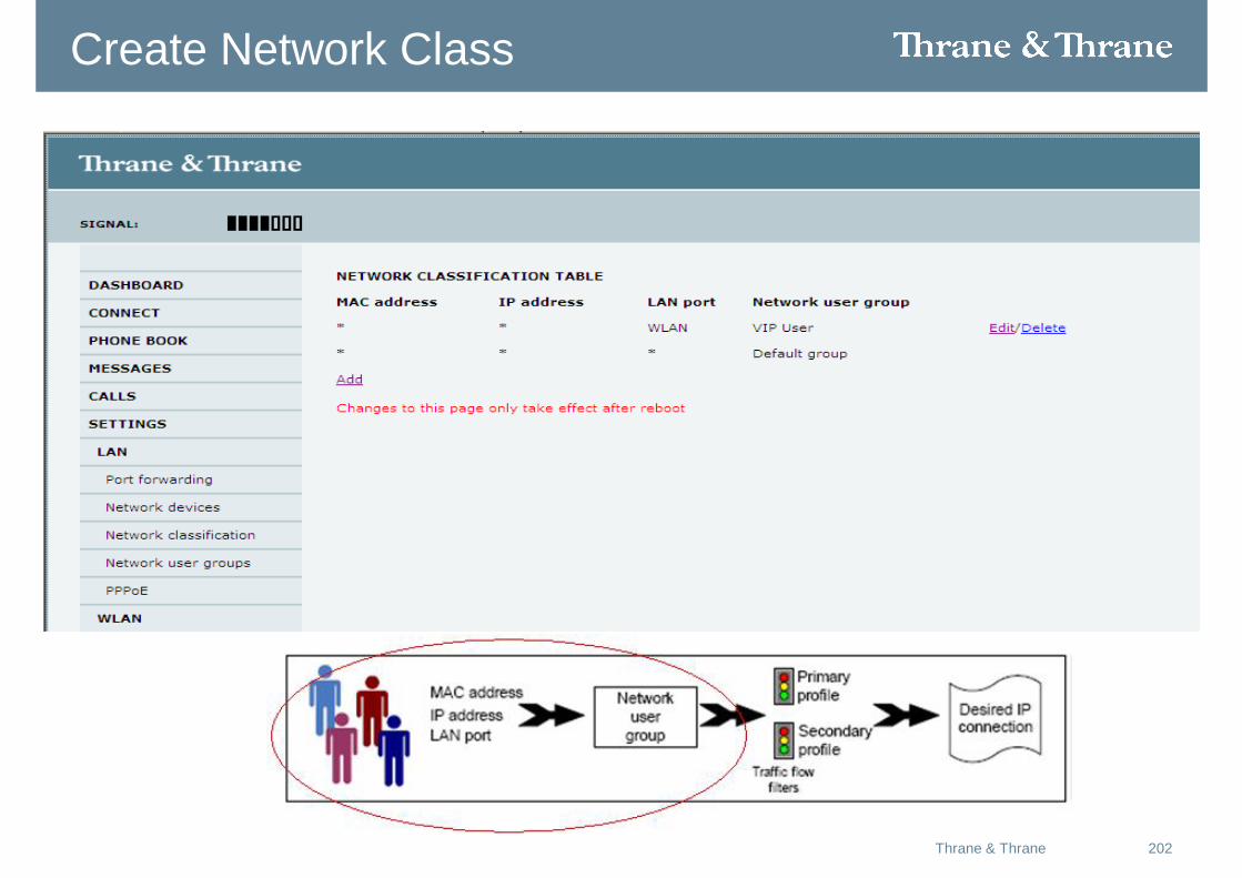
Using the network classification table
The network classification table is used for making an association between network devices and network user groups.
• Each entry in the table shows MAC address, IP address, LAN port and network user group.
• When a network device is connected, the terminal runs through the network classification table to check if the new connection matches any of the entries in the table.
• When a match is found, the terminal establishes a PDP context and the device is ready for use with the terminal.
175Thrane & Thrane
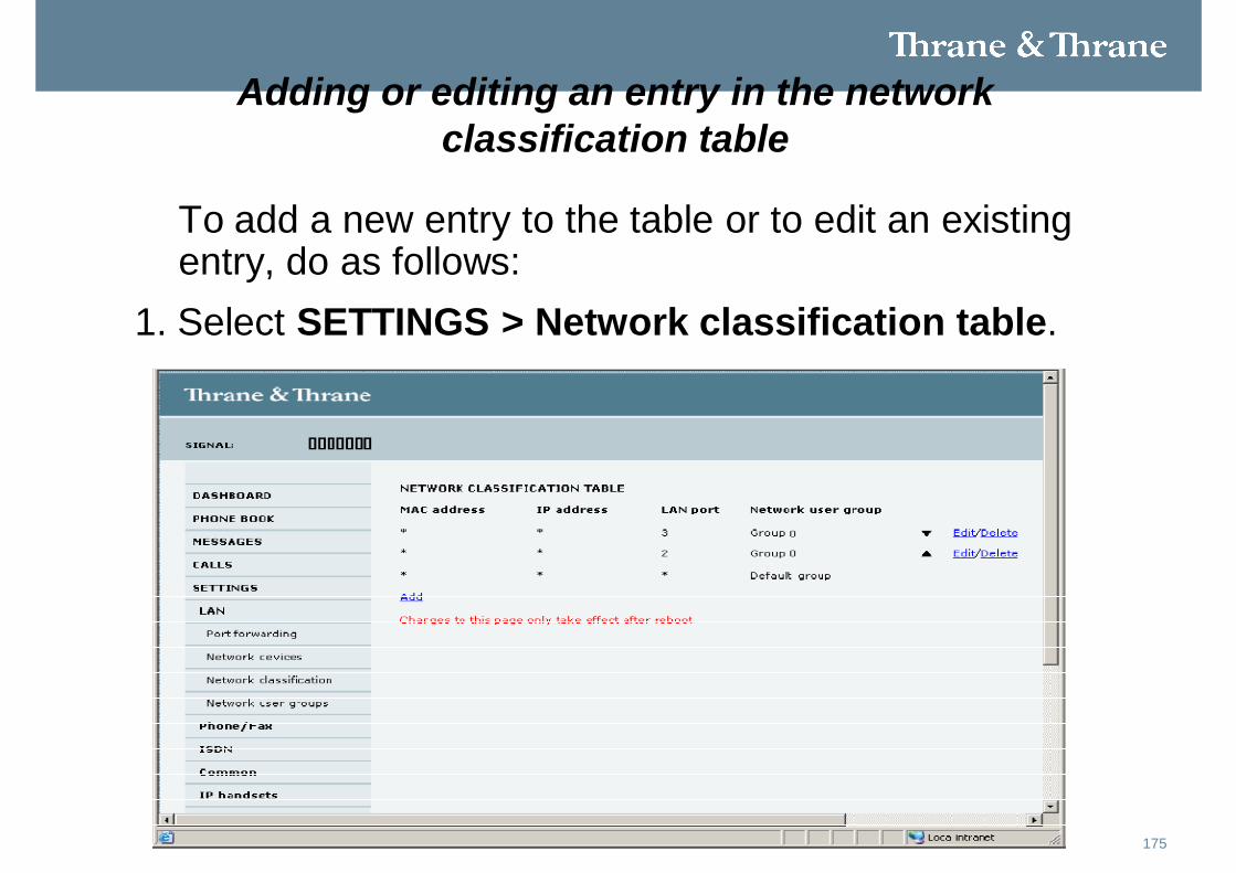
Adding or editing an entry in the network classification table
To add a new entry to the table or to edit an existing entry, do as follows:
1. Select SETTINGS > Network classification table.
176Thrane & Thrane
Adding or editing an entry in the network classification table
cont.The network classification table shows which devices are associated with
which LAN ports and network user groups. An Asterisk (*) is a “wild card”,
meaning that any value is accepted.
2. Click Edit next to the entry you want to edit, or click Add at the bottom of
the list.
3. Click Add next to a network device you want to use, or type in the MAC address manually at the top of the page.
4. Select the LAN port and Network user group you want to associate with the device.
5. Click Apply.
177Thrane & Thrane
Removing an entry in the network classification table
• In the network classification table, click Delete next to the entry you want to delete.
178Thrane & Thrane
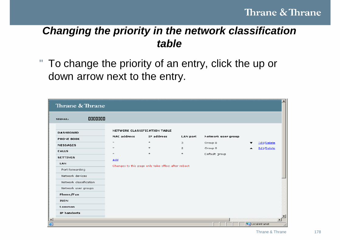
Changing the priority in the network classification table
• To change the priority of an entry, click the up or down arrow next to the entry.
179Thrane & Thrane
Changing the priority in the network classification table cont.
• Connections are evaluated in the order they are listed. The first entry (and only the first entry) that matches the properties of the connected device is applied,
• meaning that the connection will be using the settings of the user group assigned to that entry.
• The Default user group is always last, so it is only used if none of the other entries match the properties of the connected device.
180Thrane & Thrane
• This presentation is intended to be used as a basic training aid only.
• There are other configuration considerations that will need to be entered such as antenna types, handset types, Programmed cable losses, as well as Navigation sources; depending on whether AHRS, IRS or NRS is connected.
• Those additional considerations will be discussed in greater detail in the installation and users manuals for the AERO-SB Lite.
181May 2008Thrane & Thrane
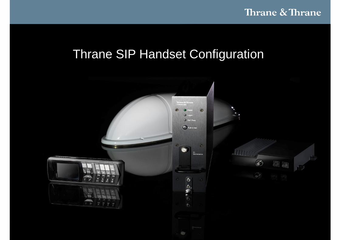
Thrane SIP Handset Configuration
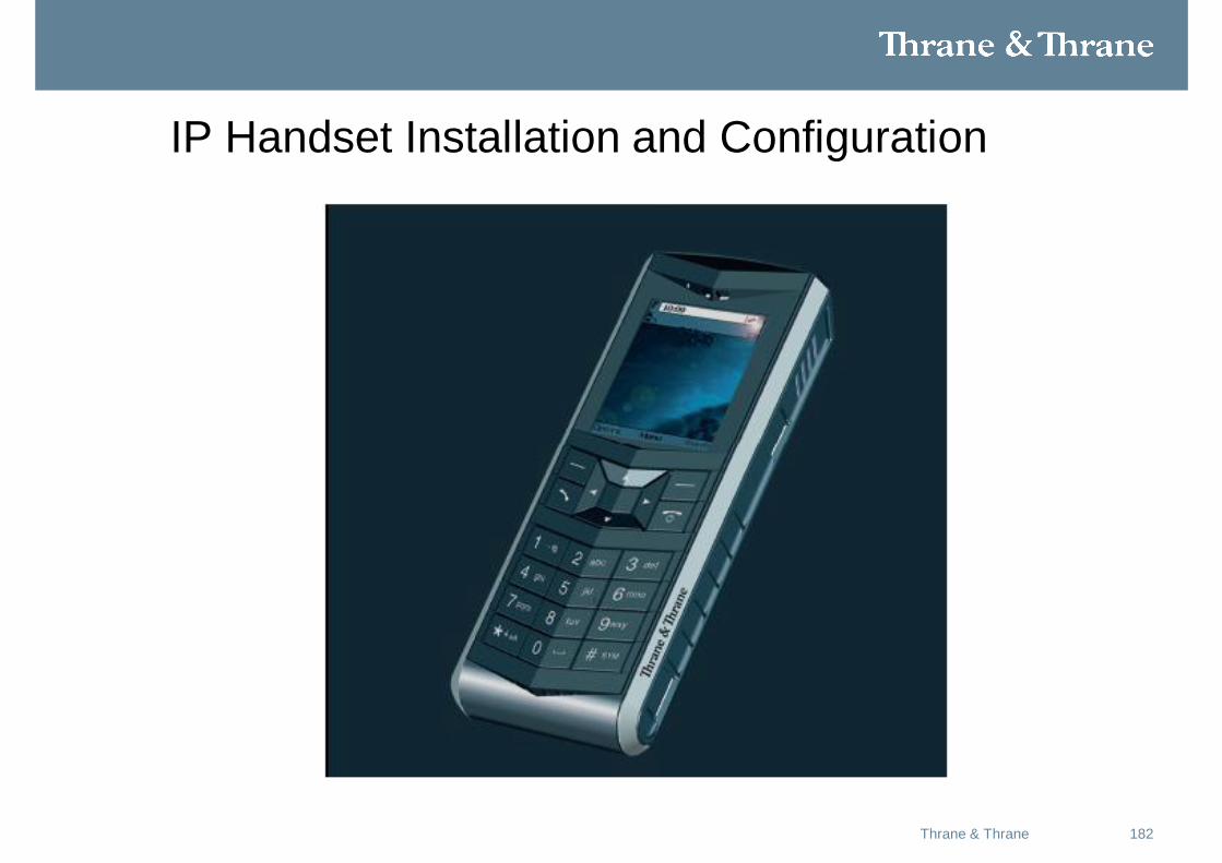
IP Handset Installation and Configuration
182Thrane & Thrane
183Thrane & Thrane
Features
• Voice communications over IP based network
• Stored contact list with up to 100 entries
• Built-in web interface (Windows CE 6.0)
• Color TFT screen (Thin-film transistor)
• Menu options for SBB terminals
• SIP to low cost voice or SIP to ground
184Thrane & Thrane
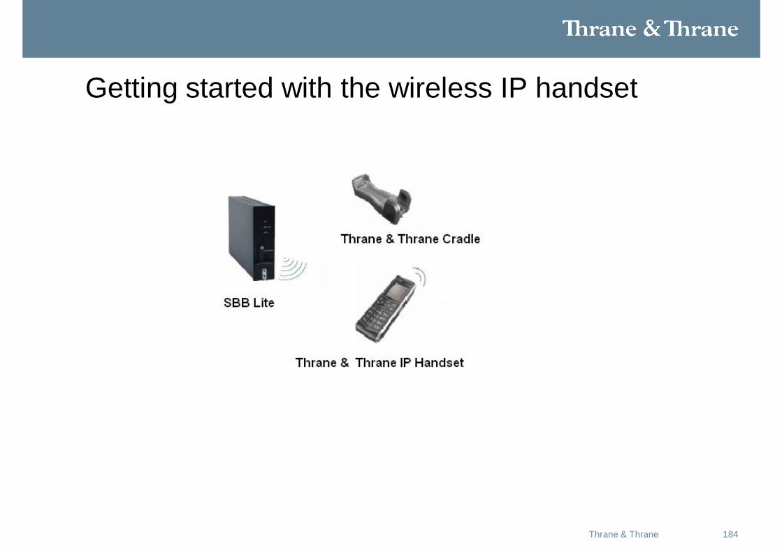
Getting started with the wireless IP handset
185Thrane & Thrane
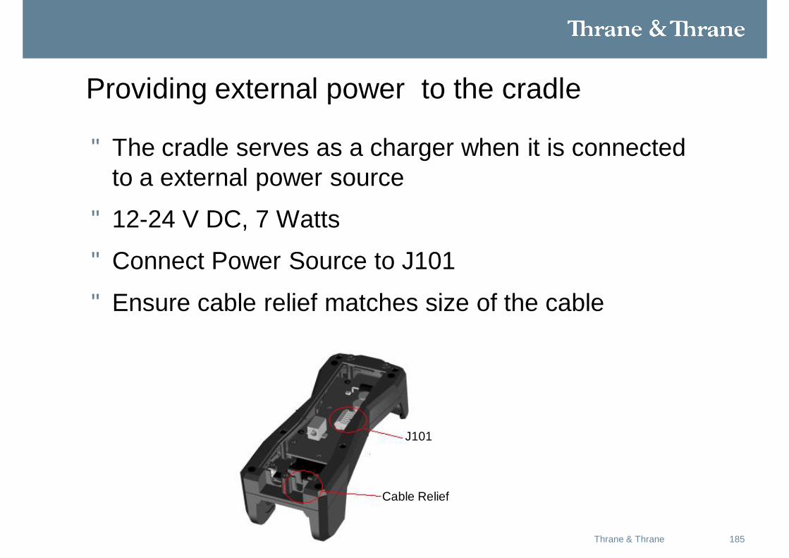
Providing external power to the cradle
• The cradle serves as a charger when it is connected to a external power source
• 12-24 V DC, 7 Watts
• Connect Power Source to J101
• Ensure cable relief matches size of the cable
J101
Cable Relief
186Thrane & Thrane
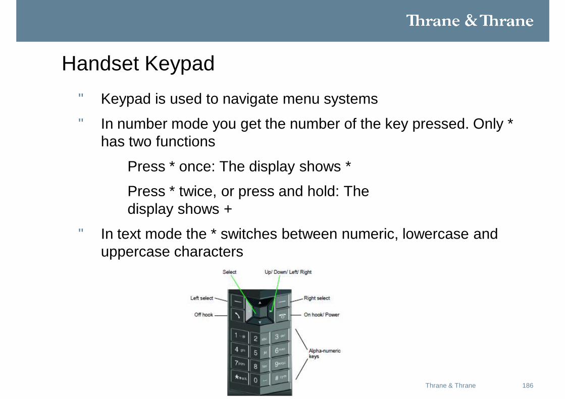
Handset Keypad • Keypad is used to navigate menu systems
• In number mode you get the number of the key pressed. Only * has two functions
Press * once: The display shows *
Press * twice, or press and hold: The display shows +
• In text mode the * switches between numeric, lowercase and uppercase characters
187Thrane & Thrane
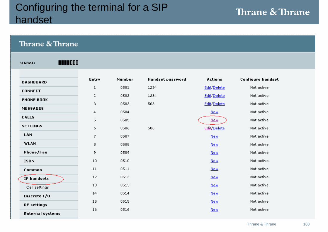
Configuring the terminal for a SIP handset
• Connect to the SBB Lite via any of the ehternet ports
• Browse to the terminal IP address. (Default is 192.168.0.1)
• Select Settings\IP handsets
• Select “new” from the actions colum.
188Thrane & Thrane
Configuring the terminal for a SIPhandset
189Thrane & Thrane
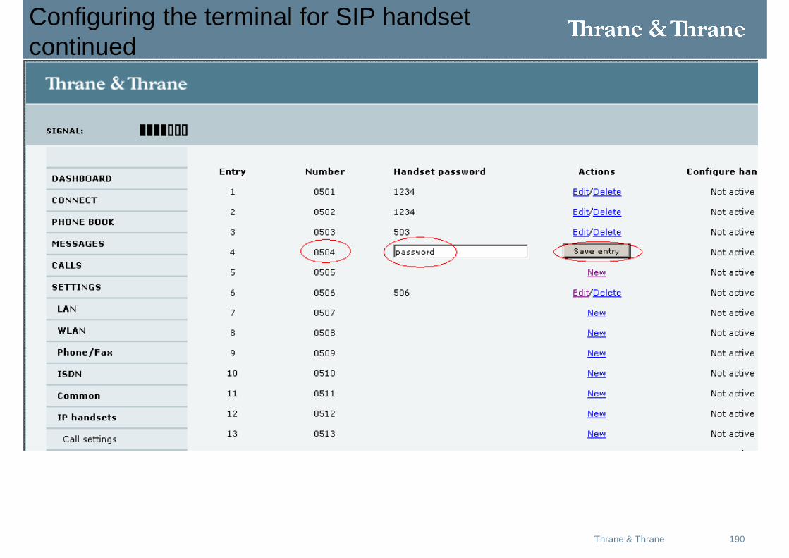
Configuring the terminal for a SIPhandset Continued
• Enter a 4 character unique password
• Select the “save” tab.
• You will need to remember the password and handset ID number. This information will be entered into the Thrane IP Hanset to complete setup
190Thrane & Thrane
Configuring the terminal for SIP handset continued
191Thrane & Thrane
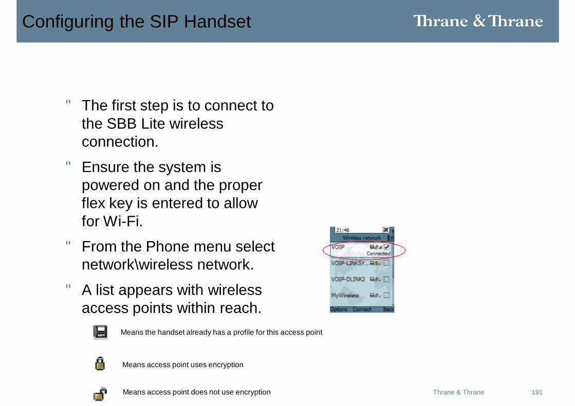
Configuring the SIP Handset
• The first step is to connect to the SBB Lite wireless connection.
• Ensure the system is powered on and the proper flex key is entered to allow for Wi-Fi.
• From the Phone menu select network\wireless network.
• A list appears with wireless access points within reach.
Means the handset already has a profile for this access point
Means access point uses encryption
Means access point does not use encryption
192Thrane & Thrane
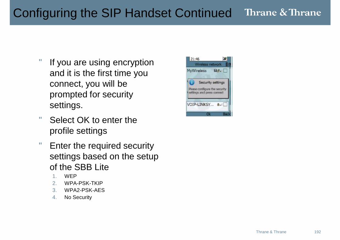
Configuring the SIP Handset Continued
• If you are using encryption and it is the first time you connect, you will be prompted for security settings.
• Select OK to enter the profile settings
• Enter the required security settings based on the setup of the SBB Lite1. WEP2. WPA-PSK-TKIP3. WPA2-PSK-AES4. No Security
193Thrane & Thrane
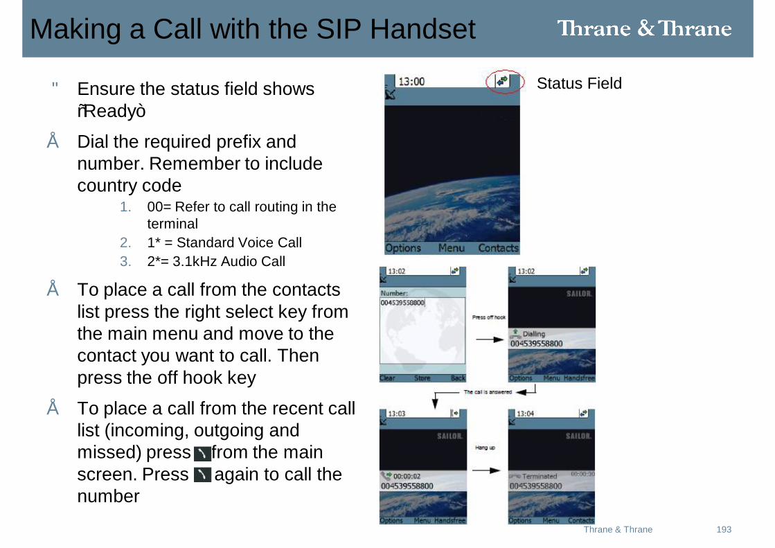
Making a Call with the SIP Handset
• Ensure the status field shows “Ready”
• Dial the required prefix and number. Remember to include country code
1. 00= Refer to call routing in the terminal
2. 1* = Standard Voice Call3. 2*= 3.1kHz Audio Call
• To place a call from the contacts list press the right select key from the main menu and move to the contact you want to call. Then press the off hook key
• To place a call from the recent call list (incoming, outgoing and missed) press from the main screen. Press again to call the number
Status Field
194Thrane & Thrane
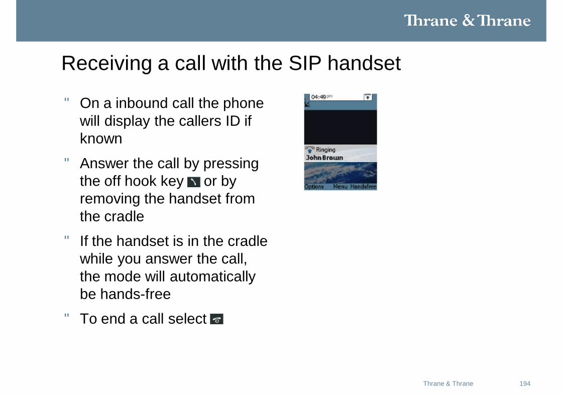
Receiving a call with the SIP handset
• On a inbound call the phone will display the callers ID if known
• Answer the call by pressing the off hook key or by removing the handset from the cradle
• If the handset is in the cradle while you answer the call, the mode will automatically be hands-free
• To end a call select
195Thrane & Thrane
Calling Ground to Air
• By Default all handsets connected to the terminal will ring on incoming calls
• Dial +870<Mobile Number>
• Refer to the information provided with your airtime subscription for mobile numbers
• There are two voice numbers, One for Standard Voice and one for 3.1kHz audio
196Thrane & Thrane
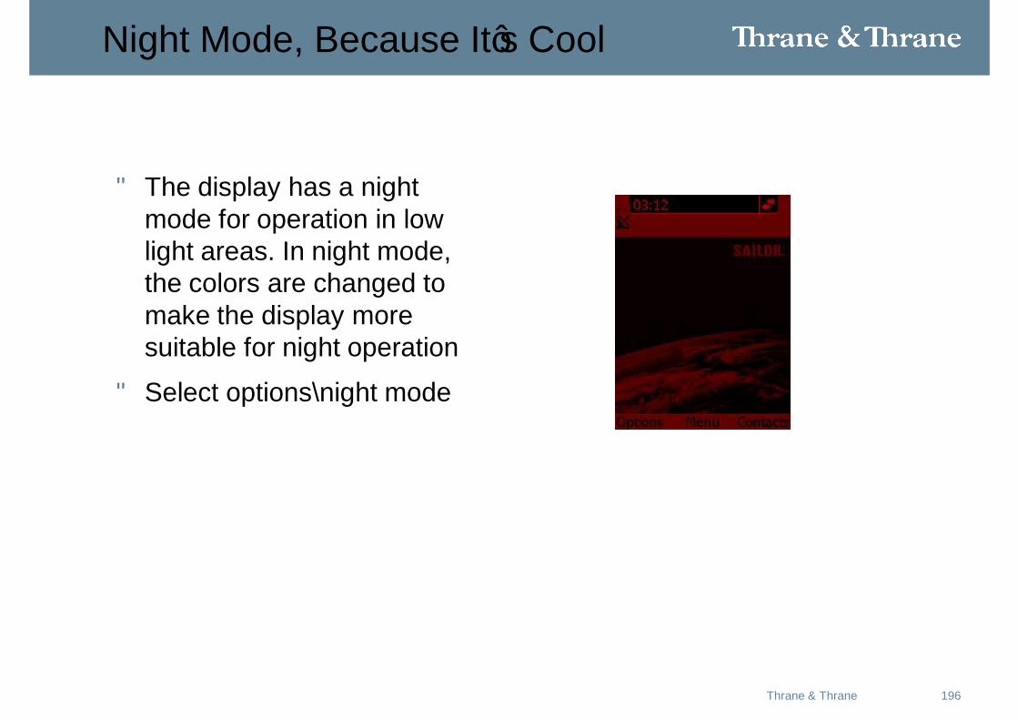
Night Mode, Because It’s Cool
• The display has a night mode for operation in low light areas. In night mode, the colors are changed to make the display more suitable for night operation
• Select options\night mode
197May 2008Thrane & Thrane
198Thrane & Thrane
Practical Application
VIP Passenger Requirements• Web Browsing Using Background Data
• Video Conference Using 32k QOS
• End To End Voip call (Cisco, Skype,Soft Phone etc.) Using 16k QOS
199May 2008Thrane & Thrane
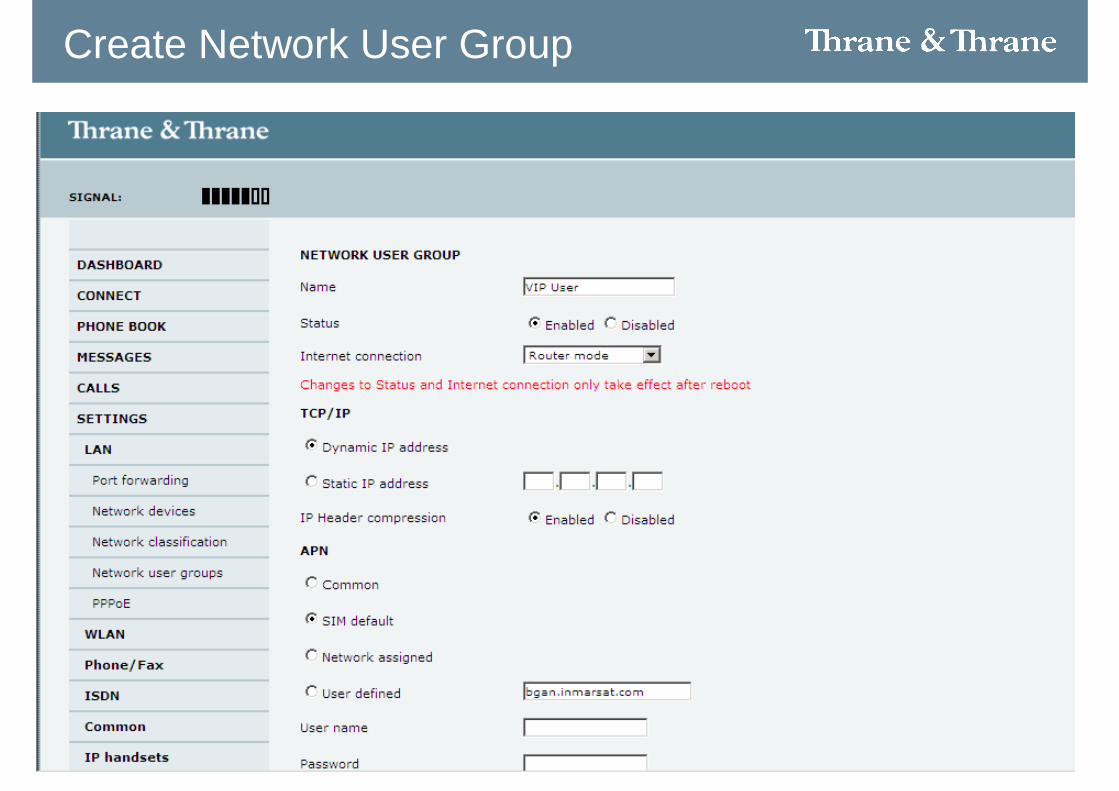
Create Network User Group
200Thrane & Thrane
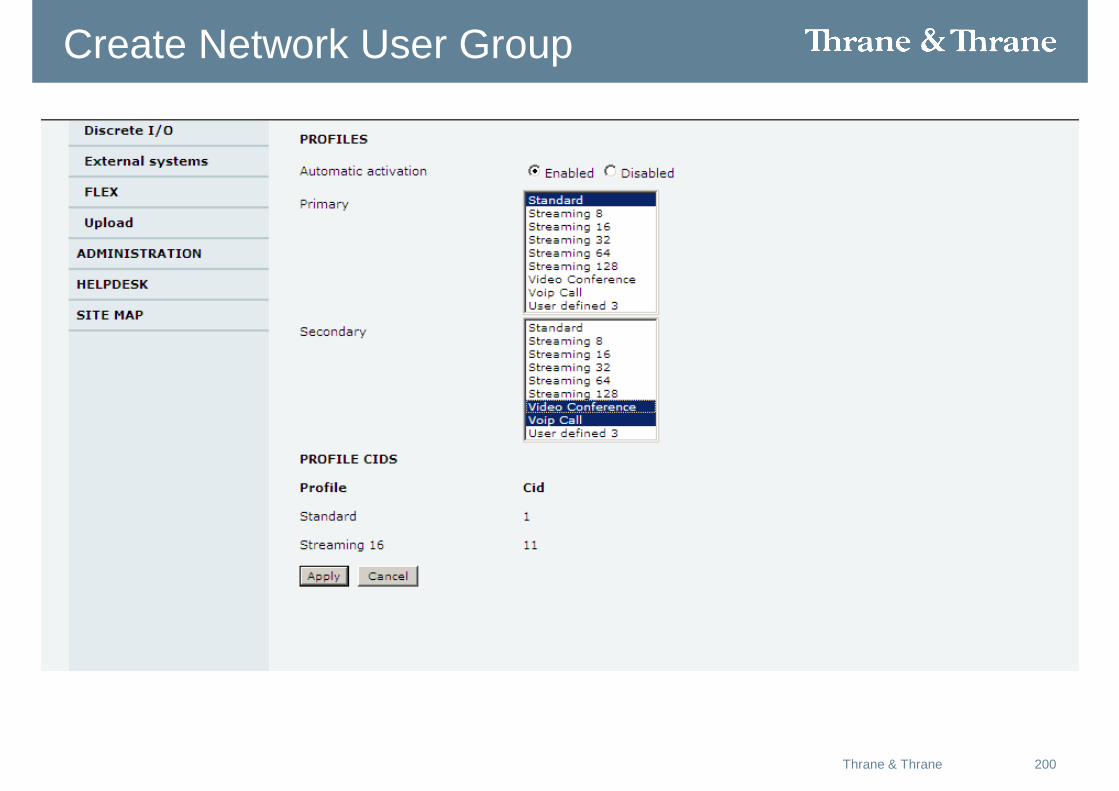
Create Network User Group
201Thrane & Thrane
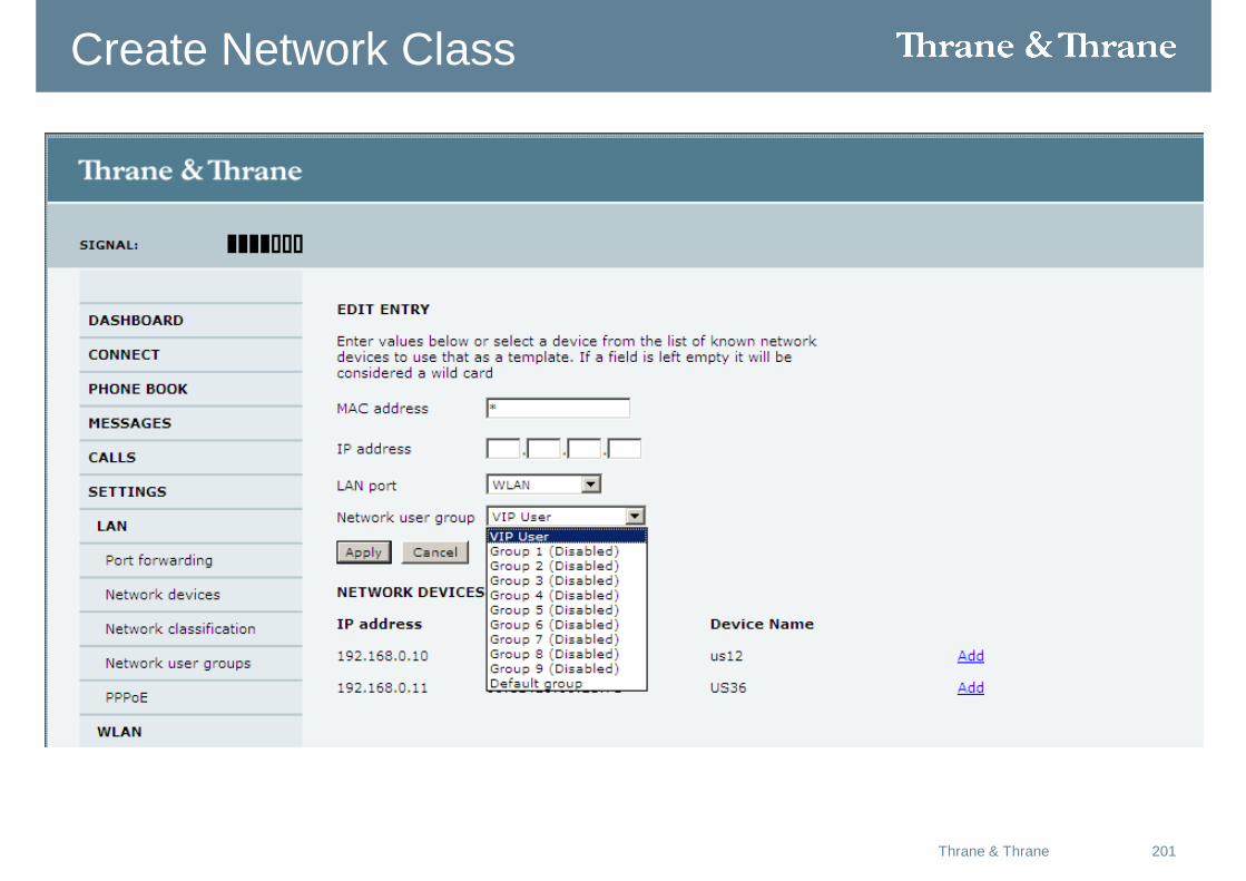
Create Network Class
202Thrane & Thrane
Create Network Class
203Thrane & Thrane
Create TFT Filter Voip
204Thrane & Thrane
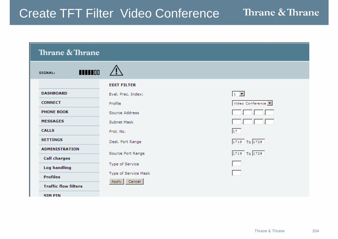
Create TFT Filter Video Conference
205Thrane & Thrane
Create TFT Filter Video Conference
206Thrane & Thrane
Dashboard
207Thrane & Thrane
Practical Application #2
Video Surveillance• Stream Video from a onboard camera 128k QOS
• Encrypted
208Thrane & Thrane
Create Network User Group
209Thrane & Thrane
Create Network User Group
210Thrane & Thrane
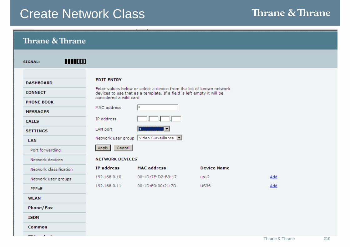
Create Network Class
211Thrane & Thrane
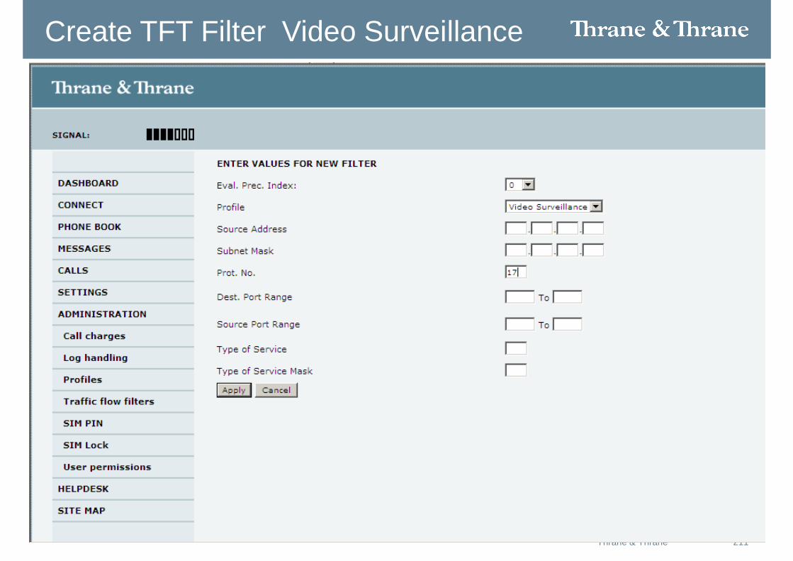
Create TFT Filter Video Surveillance
212Thrane & Thrane
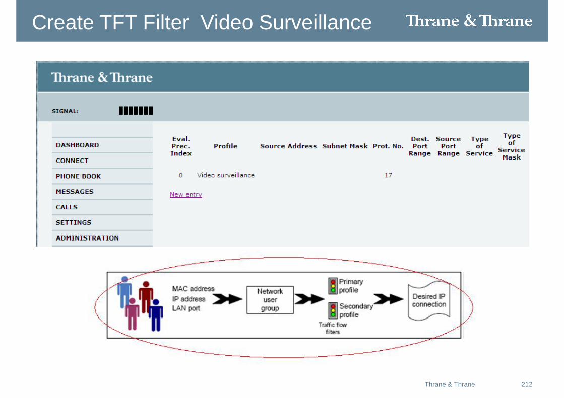
Create TFT Filter Video Surveillance
213Thrane & Thrane
Hands on Configuration and Troubleshooting
214Thrane & Thrane
Configuration
• Configure the system for use with an IGA
• Configure the system for use with an HGA
• Configure the system for use with an IRS
• Configure the system for use with an AHRS
• Set RF cable loss parameters
• Set incoming phone call types
• Set out going phone call types
• Set user groups
• Set TFT’s
• Software Upload
215Thrane & Thrane
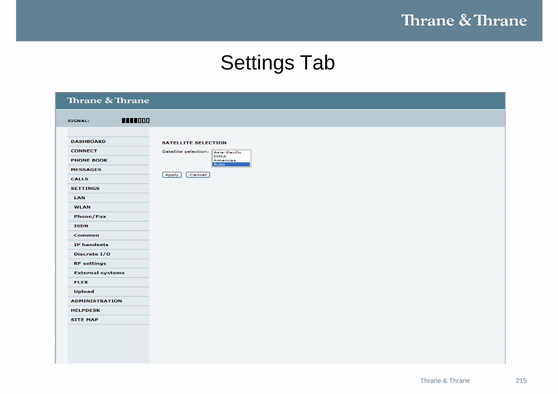
Settings Tab
216Thrane & Thrane
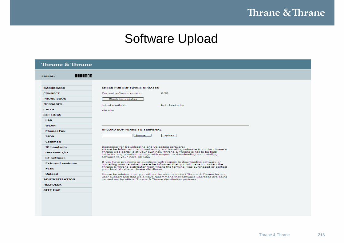
Software Upload
217Thrane & Thrane
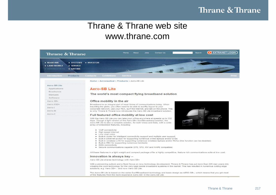
Thrane & Thrane web sitewww.thrane.com
218Thrane & Thrane
Software Upload
219Thrane & Thrane
Troubleshooting
• Help Desk
• Diagnostic report
• Event list
• Event log
• Self test
• Bite codes
• Debug commands
220Thrane & Thrane
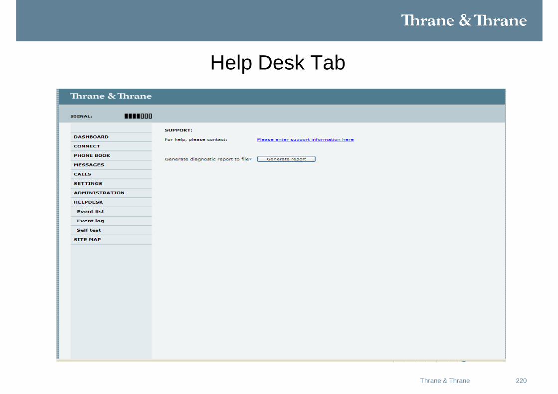
Help Desk Tab
221Thrane & Thrane
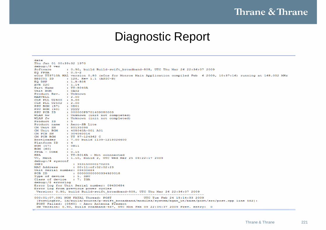
Diagnostic Report
222Thrane & Thrane
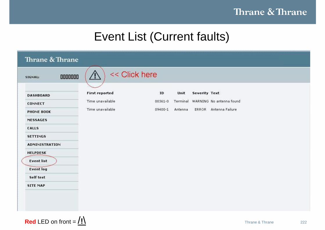
Event List (Current faults)
Red LED on front = /!\
223Thrane & Thrane
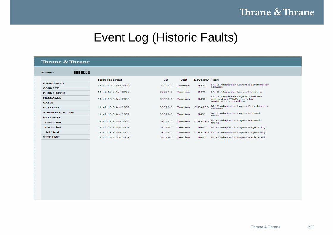
Event Log (Historic Faults)
224Thrane & Thrane
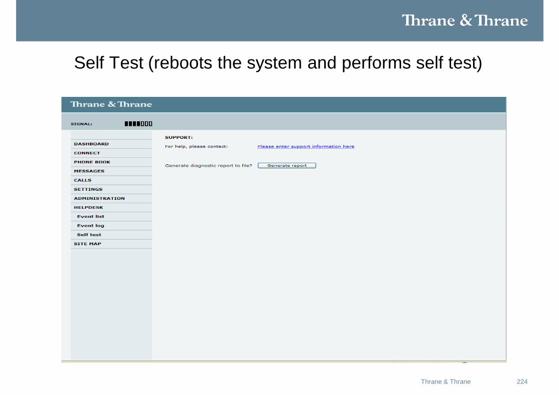
Self Test (reboots the system and performs self test)
225Thrane & Thrane
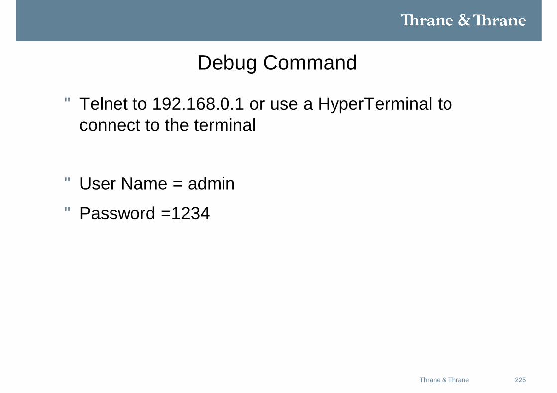
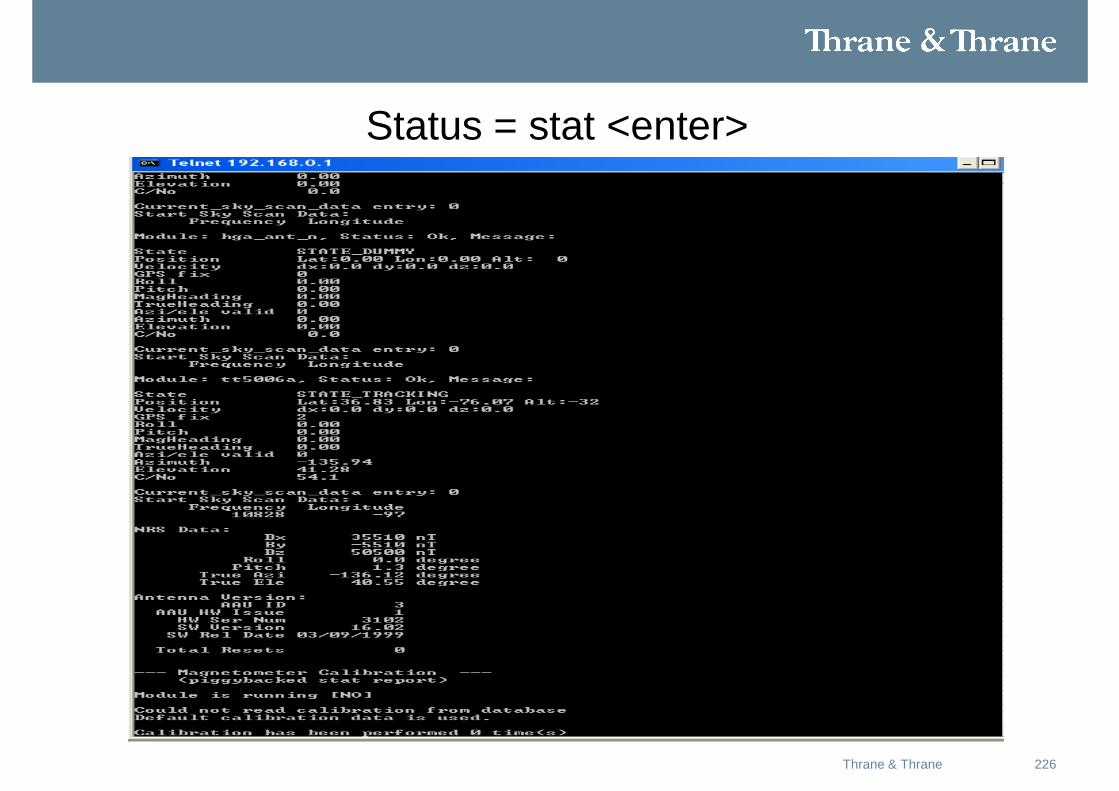
Debug Command
• Telnet to 192.168.0.1 or use a HyperTerminal to connect to the terminal
• User Name = admin
• Password =1234
226Thrane & Thrane
Status = stat <enter>
227Thrane & Thrane
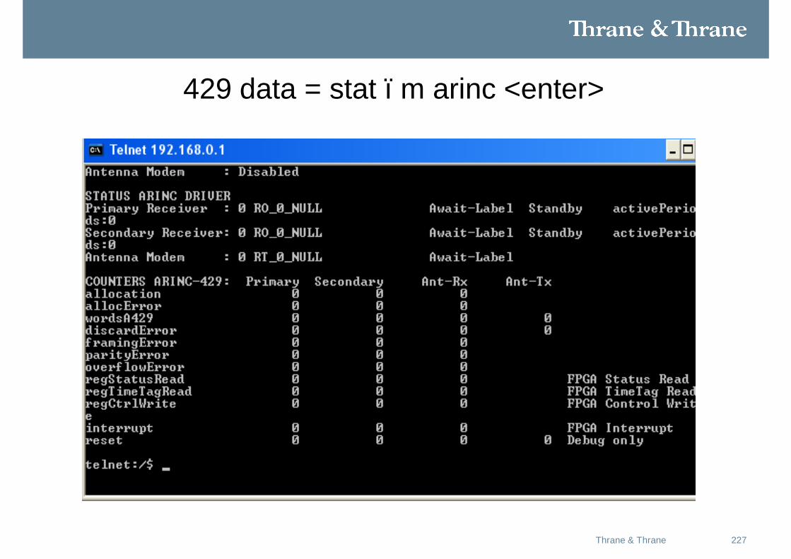
429 data = stat –m arinc <enter>
228Thrane & Thrane
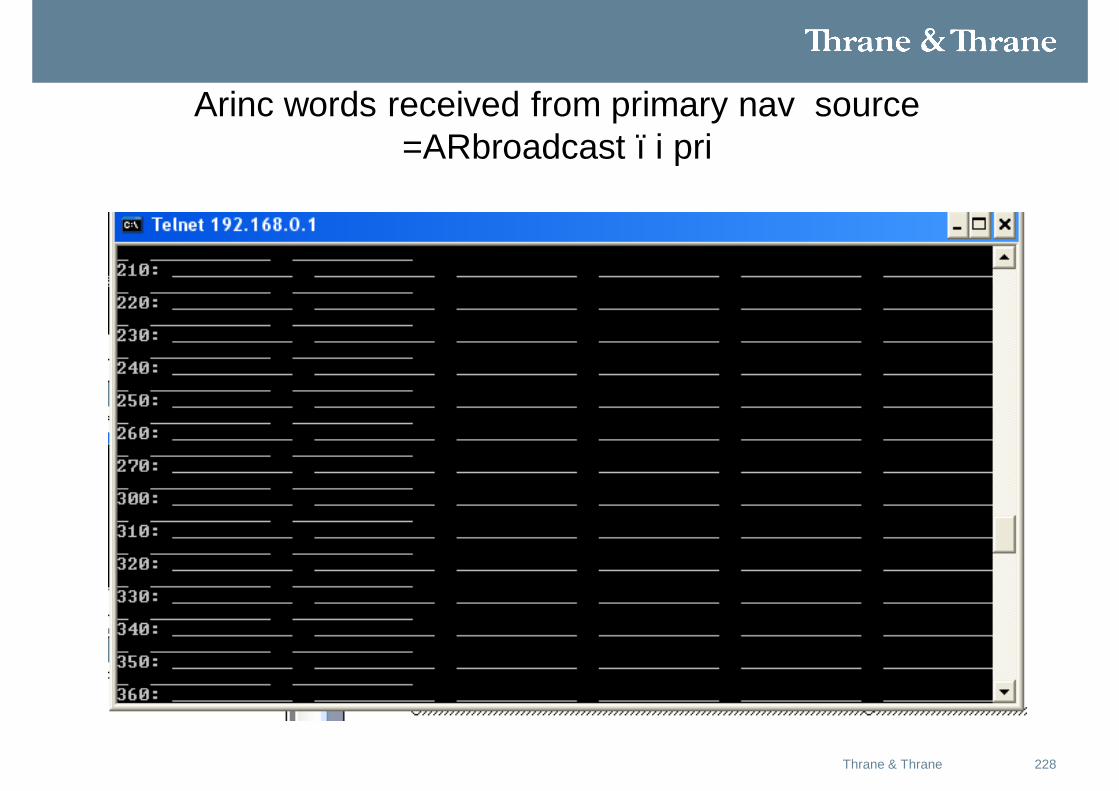
Arinc words received from primary nav source =ARbroadcast –i pri
229Thrane & Thrane
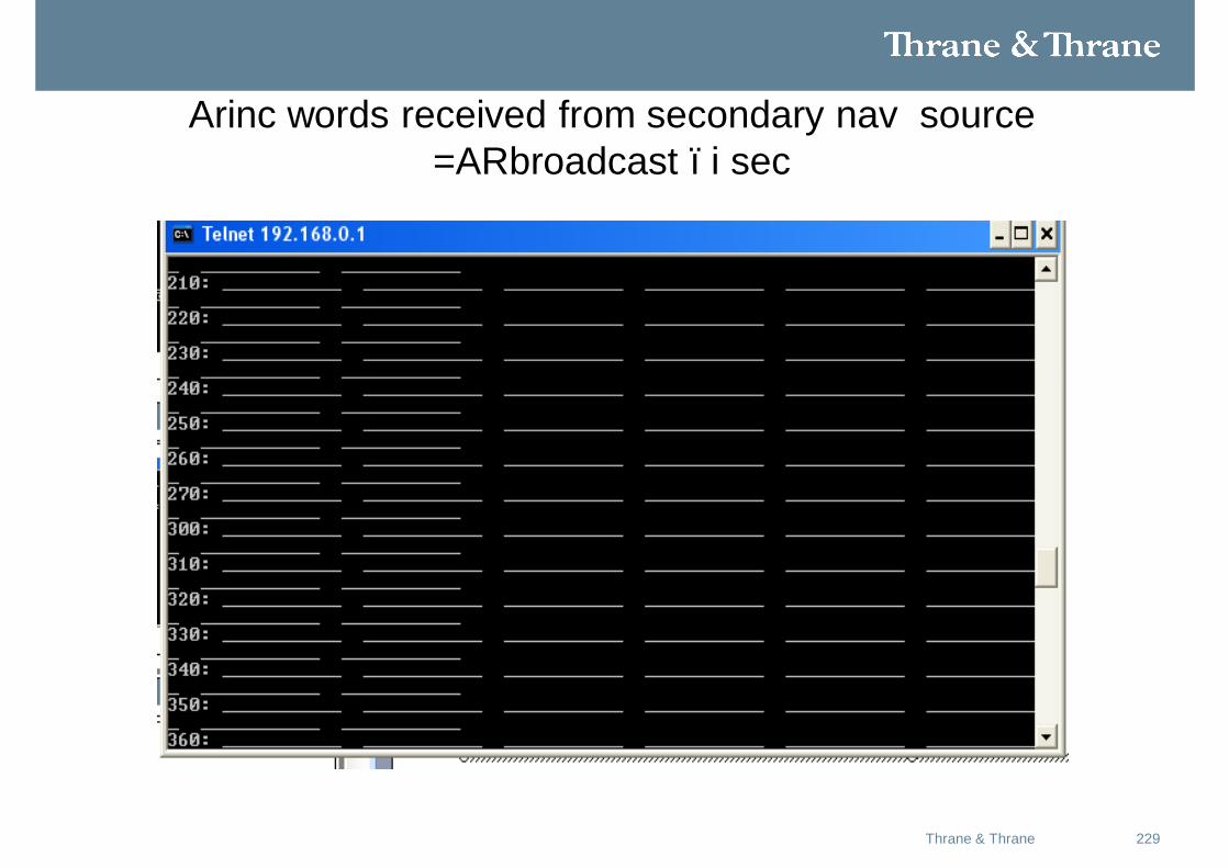
Arinc words received from secondary nav source =ARbroadcast –i sec
230Thrane & Thrane
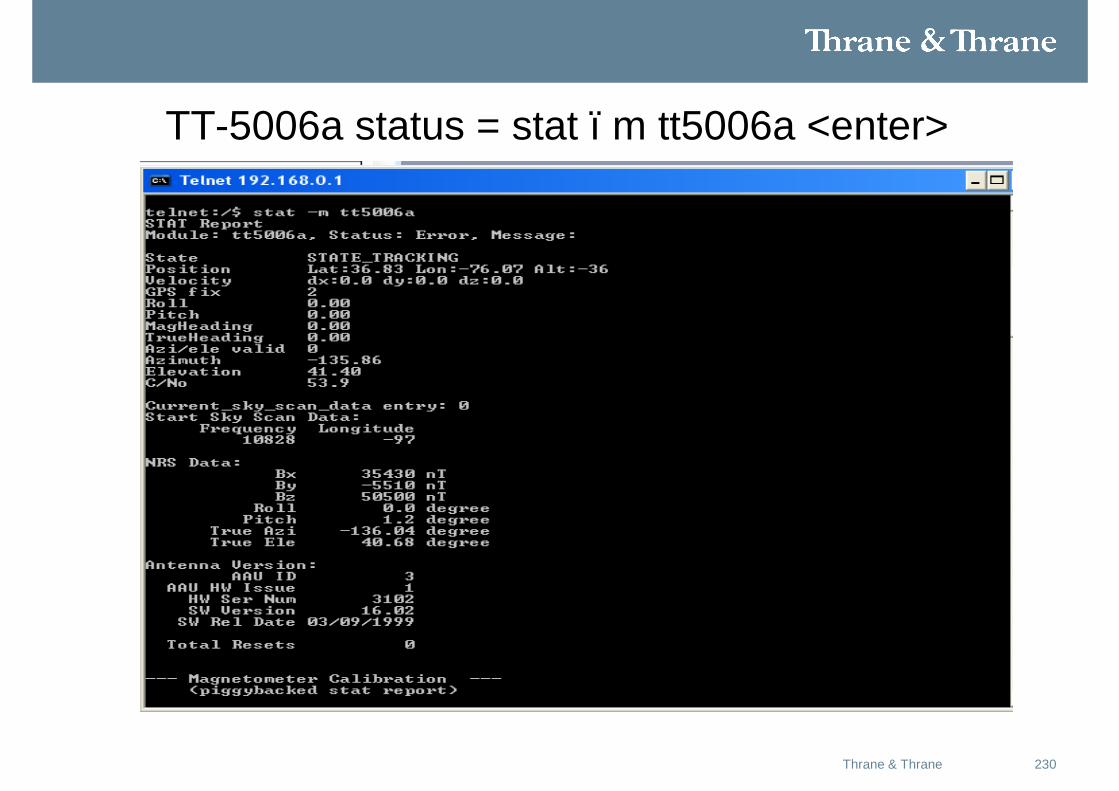
TT-5006a status = stat –m tt5006a <enter>
231Thrane & Thrane
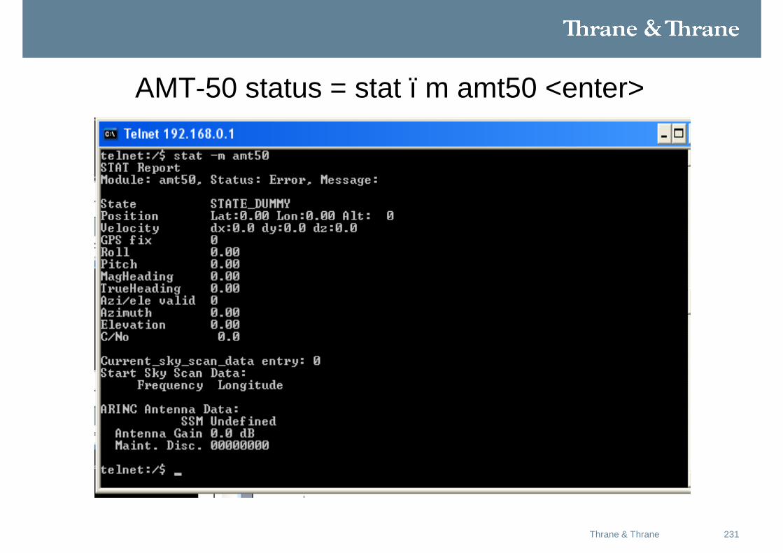
AMT-50 status = stat –m amt50 <enter>
232Thrane & Thrane
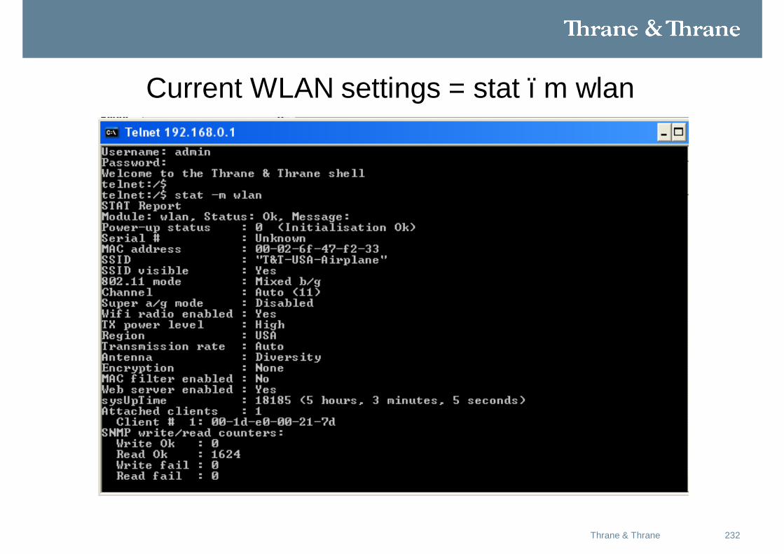
Current WLAN settings = stat –m wlan
233Thrane & Thrane
Won’t display a wireless connection?
234Thrane & Thrane
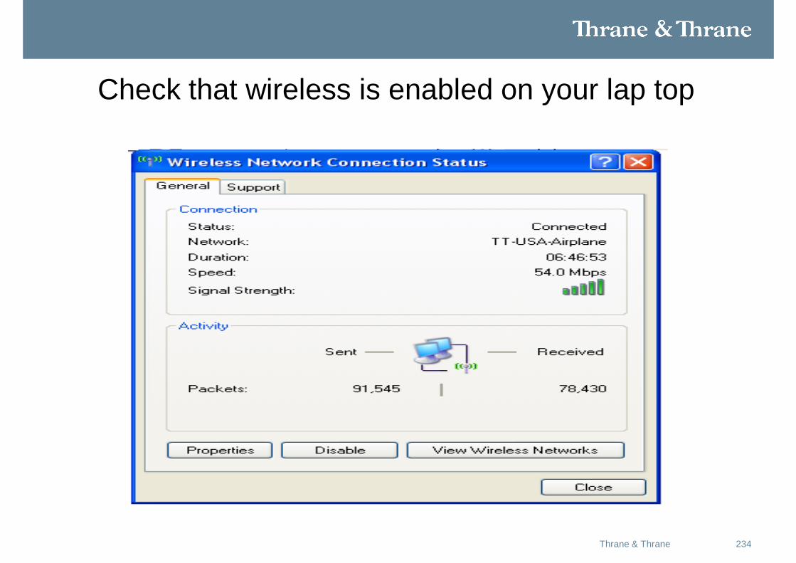
Check that wireless is enabled on your lap top
235Thrane & Thrane
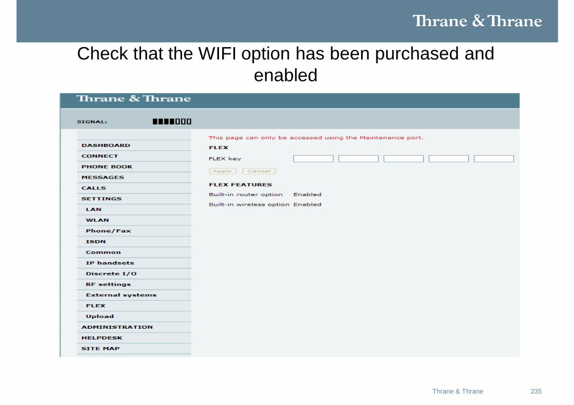
Check that the WIFI option has been purchased and enabled
236Thrane & Thrane
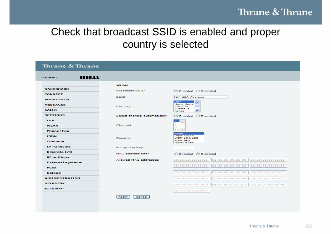
Check that broadcast SSID is enabled and proper country is selected
237Thrane & Thrane
Won’t connect to the internet?
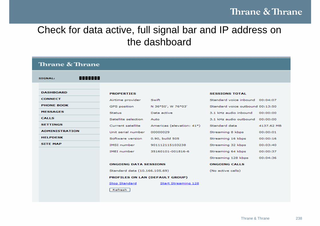
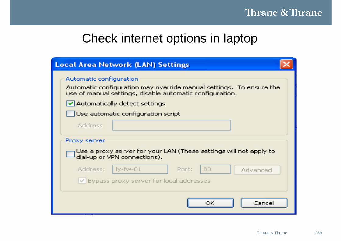
238Thrane & Thrane
Check for data active, full signal bar and IP address on the dashboard
239Thrane & Thrane
Check internet options in laptop
240Thrane & Thrane
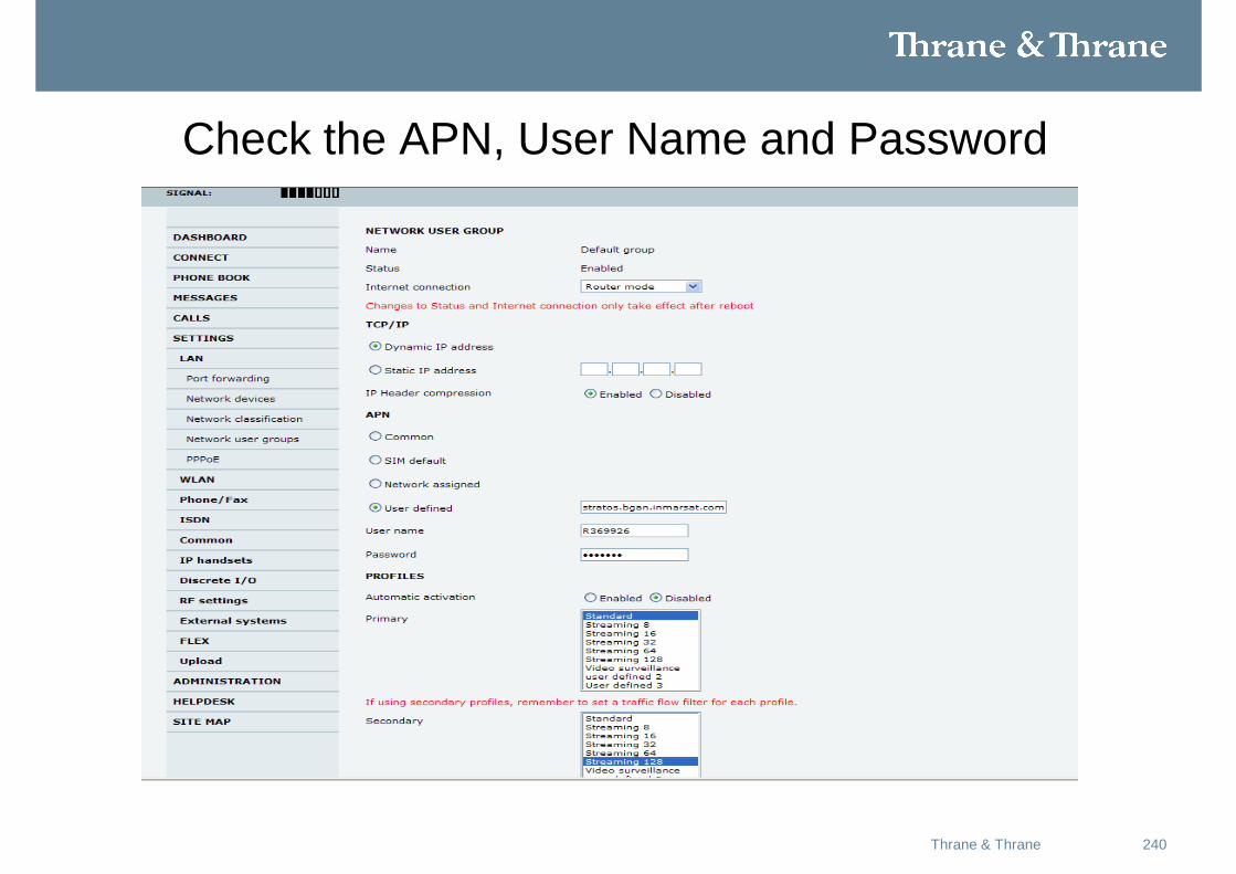
Check the APN, User Name and Password
241Thrane & Thrane
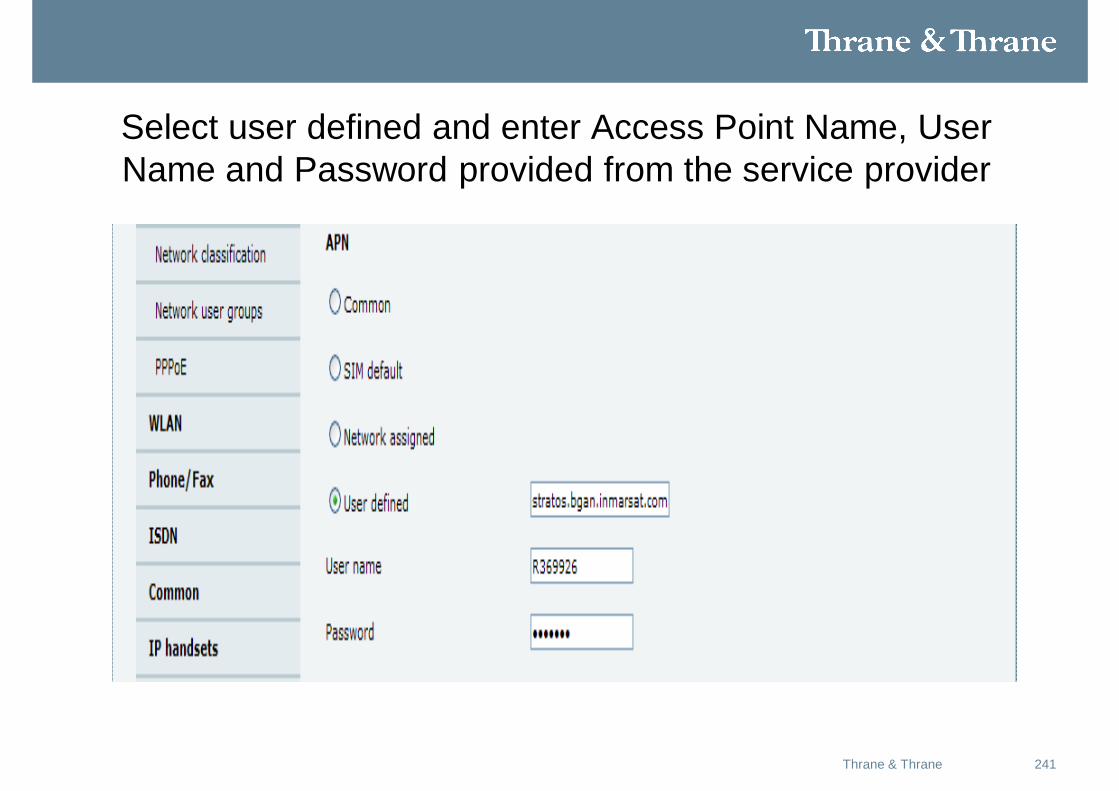
Select user defined and enter Access Point Name, User Name and Password provided from the service provider

242May 2008Thrane & Thrane