Embed Size (px)
Citation preview

1 AW07A Instruction Manual
AW07A HF/VHF/UHF Antenna Analyzer V1.6

2
INTRODUCTION:
AW07A antenna analyzer is a compact battery powered RF impedance analyzer. It can test the SWR status of your antenna, measure
the impedance and reactance component and help you to solve antenna problems. This unit combines six basic parts: a variable oscillator,
frequency counter, independent oscillator, 50 ohm RF bridge detector, an A-D converter, and microcontroller. This compact product was built
to feed the need for the solid construction and field test. The operating frequency range of this unit goes from HF, and extends up to 490MHz.
It is specially designed for analyzing 50ohm antenna system. It measures RF impedances from a few ohms to several hundred ohms. The
AW07A is also an L/C meter, measuring the values of capacitors and inductors. Additionally, it could be a non-precision signal source and
frequency counter. With a built-in RF strength meter, it tests the RF field strength near your antenna system, and it’s very useful when you
need to know the RF interference status around your station. The AW07A also functions as a non-precision signal source and frequency
counter. The operating frequency range of this unit extends from 1.5 to 71 MHz in six overlapping bands, and includes SWR measurements
on 85-185MHz, 300-490 MHz.

3
FEATURES LIST:
1. SINGNAL SOURCE
2. CAPACITANCE METER
3. INDUCTANCE METER
4. SHOW REACTANCE VALUE
5. SHOW IMPEDANCE VALUE
6. SWR VALUE FROM 1.1 TO 9.99
7. RF STRENGTH METER
8. FREQUENCY COUNTER
SPECIFICATIONS:
1. Band Coverage : 160m, 80m, 40m, 20/30m,10/15m, 6m, 2m, 70cm
2. RF Output Level: 2Vpp
3. SWR Range: 1~9.9

4
4. Impedance Range: 10~500ohm
5. Reactance Range:
6. L measurement Range:
7. C measurement Range:
8. External Power: DC 10.8~12V
9. Battery: 8 * AA Alkaline Battery
10. Power Consumption : < 150mA (HF Bands, B/L Off), < 165mA (VU Bands, B/L Off)
11. Weight: 0.6 kg
12. Size: 155 (W) ×100 (D) ×55(H)

5
GENERAL GUIDE:
When you turn on the analyzer by pressing the “POWR” switch down, a sequence of messages will be displayed on the LCD. It’s the call
sign of designer and backlight function indicator.
To turn up the backlight, you need
to press and hold the “Up” button within
the time that the message showed on
the screen. If the message is cleared,
you need to power off the unit and
re-power on again for the operation.
If you do nothing, AW07A will entry
next Menu (SWR Analyzer or Frequency
Counter) in 1 Sec. Press “Down” button
to Frequency Counter Mode, while
pressing “Up” button entering the Antenna Test Mode. Also the current DC voltage is displayed.

6
Please see the picture below for the front panel operation.

7
BAND SELECTING:
The 2 switches on the left-upper side of the analyzer are the switches to
Change band ranges. By pressing the two switches up and down, the frequency
ranges change from HF to UHF.
EXAMPLES:
SWITCH TO UHF:
1. POWER ON
2. Press the button “Up” to Ant Mode
3. Press the HF/UV switch DOWN
4. Keep the U/V switch UP
Notes: VHF: 85-185MHz continuous
SWITCH TO VHF:
1. POWER ON

8
2. Press the button “Up” to Ant Mode
3. Press the HF/UV switch DOWN
4. Keep the U/V switch DOWN
Notes: UHF: 300-490MHz continuous
SWITCH TO HF:
1. POWER ON
2. Press the button “Up” to Ant Mode
3. Keep the HF/UV switch UP
4. Press the Up/Down button on the center position of your analyzer to change to different HF
bands (BAND A to F)
Notes: Frequency range in HF bands (BAND A to F), a small frequency overlap may be possible, please
see the following:

9

10
Antenna Mode:
Press the “Up” key on “SWR Analyzer
or Frequency Counter” menu will enter the
Antenna Mode.
In this mode, it will test and show your antenna system’s several parameters, such as SWR, Z, Rs, Jx
values. All of these parameters are showed on the LCD.
ANTENNA TEST EXAMPLES:
HF and VHF test:
1. TURN ON your analyzer (It will show the power on message)
2. Press “Up” for the backlight on or off
3. Press “Up” to enter the Antenna Analyzer Mode
4. Switch to the band you want to operate (See the band selecting part)
5. Turn the “Tuning Konb” to your frequency point to see the tested results (SWR, Z, Rs, Jx).
11
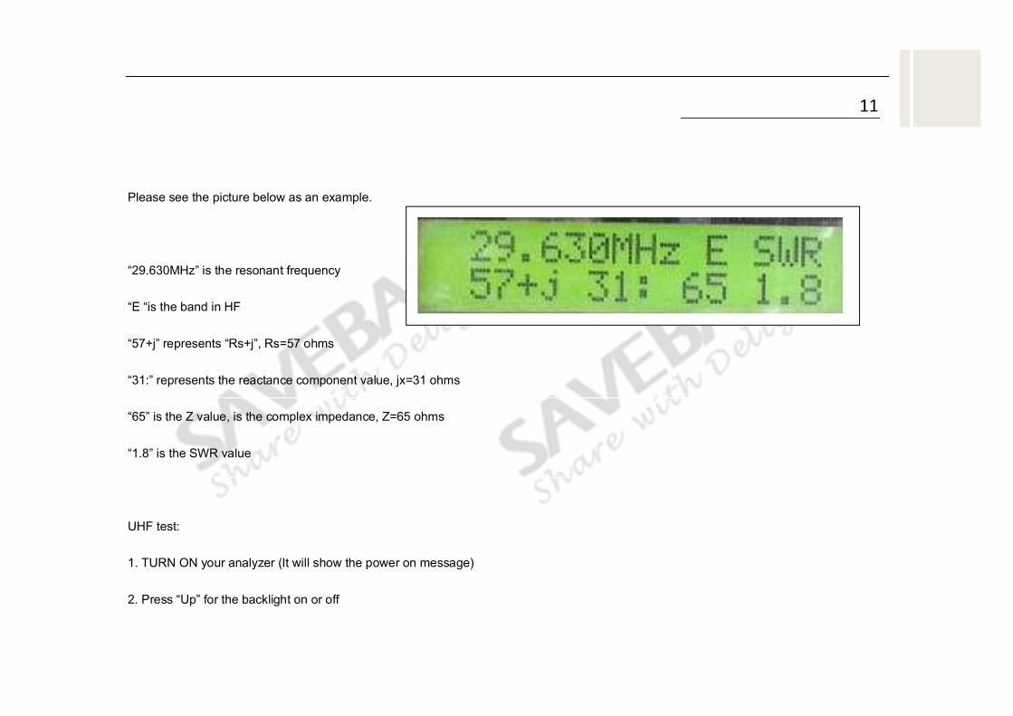
Please see the picture below as an example.
“29.630MHz” is the resonant frequency
“E “is the band in HF
“57+j” represents “Rs+j”, Rs=57 ohms
“31:” represents the reactance component value, jx=31 ohms
“65” is the Z value, is the complex impedance, Z=65 ohms
“1.8” is the SWR value
UHF test:
1. TURN ON your analyzer (It will show the power on message)
2. Press “Up” for the backlight on or off

12
3. Press “Up” to enter the Antenna Analyzer Mode
4. Switch to the band you want to operate (See the band selecting part)
5. Turn the “Tuning Konb” to your frequency point to see the tested results (SWR only).
Please see the picture below as an example.
“418.644MHz” is the resonant frequency
“U “is the band in UHF
“1.2” represents the SWR value
“===” is the bargraph display of the SWR
The left example shows the SWR status when no
antenna connected to AW07A

13
Frequency Counter Mode:
Press the “Down” key on “SWR
Analyzer or Frequency Counter” menu will
enter the Frequency Counter Mode.
In this mode, it will test and show the frequency of input signal source.
FREQUENCY TEST EXAMPLES:
1. TURN ON your analyzer (It will show the power on message)
2. Press “Up” for the backlight on or off
3. Keep the “HF/UV” switch UP.
4. Press “Down” to enter the Frequency Counter Mode
5. Connect the signal source to your AW07A

14
Please see the picture below as an example.
1. “Sg” represents “Slow Gate” (Press “Down” will
switch to “Fg”, Slow Gate)
2. “f: 207.8350 MHz” is the frequency of signal source
3. “REF FS “represents the field strength, and the tested result will be showed in a bargraph
display
4. “0mV” represents the voltage level of tested signal
Notes: The Frequency Range of AW07A in Frequency Mode is 1-500MHz.The “Frequency Mode” of
AW07A has two time gate, they are expressed by “Fg” and “Sg”. “Fg” is the Fast Gate, while “Sg”
represents Slow Gate. In Fast Gate Mode, the displayed frequency is only 6 digits, counted in
MHz. In Slow Gate Mode, the displayed frequency has 7 digits, and 4 digits after the decimal
point. It’s more accurate than Fast Gate Mode. As a general rule the longer the time window the
more accurate the frequency counted. The accuracy of this counter is typically better than 0.08 %.

15
UV/HF switch must be on HF position in Frequency Counter Mode, otherwise “FREQ.C
SW Error, PSE VU/HF SW UP” will be showed on LCD. Additionally, the tested field strength
level is just for reference, is the same to field strength meter, it does not have the laboratory
accuracy. It tests the RF field strength near your antenna system, and it’s very useful when you
need to know the RF interference status around your station. If you have a strong RF
interference around your station, the antenna analyzer may be less accurate than the case in a
good RF environment. It’s because the antenna gets the interference current down to the AW07A,
and it cancels some of the transmitted power from the analyzer.
WARING: AW07A is a RF sensitive device, if you have a very strong RF interference, please stop
testing your antenna. It may damage your AW07A.
SIGNAL GENERATOR :
The AW07A is useful as a non-precision signal source. It provides a relatively pure signal of
approximately 2 Vpp (due to local legal) into 50 ohm loads. The AW07A internal source impedance is 50

16
ohms. The AW07A is not a stable generator, but has adequate stability for non-critical applications such as
alignment of broad bandwidth filters and circuits.
EXTERNAL POWER SUPPLY:
The AW07A can be used with external low voltage dc supplies .Voltage should not
be lower than 10.8 volts, and preferably not higher than 12.5 volts. The case of the
AW07A is connected directly to the negative terminal. The current consumption is 150
mA maximum on HF, and 165 mA maximum on V/UHF (all with backlight off).
The AW07A has a 2.1 mm DC power connector on the right of the TUNE Knob. This
connector is labeled “DC 10.8-12V”.
The outside conductor of the DC connector is negative, while the center conductor
positive. Inserting a power plug to the “DC 10.8-12V” connector, will disable the power from the internal
batteries.
WARNING: REVERSE POLARITY OR EXCESSIVE VOLTAGE CAN DAMAGE OR DESTROY THE

17
AW07A. NEVER APPLY MORE THAN 13 VOLTS, NEVER USE AC OR POSITIVE GROUND
SUPPLIES! NEVER ADD OR REMOVE BATTERIES WITH AN EXTERNAL POWER SUPPLY
CONNECTED TO THIS UNIT, OR WITH THE POWER SWITCH ON.
INTERNAL BATTERIES GUIDE:
After the cover mounting screws are removed, remove the entire back cover. Battery box is accessed by
removing the AW07A’s cover. Place 8×1.5V (not 1.2V) AA size batteries into the battery box. DO NOT use
external power supply when replacing batteries.
ANTENNA ADJUSTMENT HINTS:
1. Dipoles
Since a dipole is a balanced antenna, it is a good idea to put a balun at the feedpoint. The balun can be
as simple as several turns of coax several inches in diameter, or a complicated affair with many windings on

18
a ferromagnetic core.
The height of the dipole, as well as it's surroundings, influence the feedpoint impedance and feedline
SWR. Typical heights result in SWR readings below 1.5 to 1 in most installations when using 50 ohm coaxial
cable.
In general, the only adjustment available is the length of the dipole. If the antenna is too long it will
resonate too low in frequency, and if it is too short it will resonate too high.
Remember feedline length, when the antenna is not exactly the same impedance as the feedline, modifies
the impedance along the feedpoint. SWR will remain constant (except for a small reduction in SWR as the
feedline is made longer) if the feedline is a good quality 50 ohm cable. If feedline length changes SWR at any
one fixed frequency, the feedline either has common mode currents that are detuning the antenna or the
feedline is not a true 50 ohm cable. Common mode currents are caused by lack of a balun or other
installation errors, such as a feedline paralleling the antenna.

19
2. Verticals
Verticals are usually unbalanced antennas. Many antenna manufacturers incorrectly downplay the need
for a good radial system with a grounded vertical. With a good ground system, the SWR of a directly fed
quarter-wave vertical can be nearly 2 to 1. SWR often improves if the ground system (and performance) is
poor, so a low SWR with a directly fed Marconi might be a sign of inefficiency. Verticals are tuned like dipoles,
lengthening the element moves the frequency lower, and shortening the element moves the frequency
higher.