Embed Size (px)
Citation preview
Engineering Creative Solutionsfor Fluid Systems Since 1901
AWWA Butterfly Valves 3" – 20"

A Tradition of ExcellenceWith the development of the first rubber seated butterfly valve more than 80 years ago, the Henry Pratt Company became a trusted name in the flow control industry, setting the standard for product quality and customer service. Today Pratt provides the following range of superior products to the water, wastewater and power generation industries.
Butterfly Valves: from 3" to 162"
Rectangular Valves: 1' x 1' to 14' x 16'
Ball Valves — Rubber Seated: from 4" to 60" Metal Seated: from 6" to 48"
Plug Valves: from 1/2" to 72", 100% port available up to 48", 3 ways
Air Valves for Water and Wastewater: from 1/2" to 20"
Hydraulic Control Systems
Valve Controls
Energy Dissipating Valves and Fixed Energy Dissipaters
Cone Valves
Check Valves
Plunger Valves
A Commitment to Meeting The Customers’ NeedsHenry Pratt valves represent a long-term commitment to both the customer and to a tradition of product excellence. This commitment is evident in the number of innovations we have brought to the industries we serve. In fact, the Henry Pratt Company was the first to introduce many of the flow control products in use today, including the first rubber seated butterfly valve, one of the first nuclear N-Stamp valves, and the bonded seat butterfly valve.
Innovative Products For Unique ApplicationsThough many of the standard valves we produce are used in water filtration and distribution applica tions, Pratt has built a reputation on the ability to develop specialized products that help customers to meet their individual operational challenges.
Creative Engineering for Fluid SystemsPratt’s ability to provide practical solutions to complex issues is demonstrated by the following case histories.
Earthquake Proof ValvesPratt designed and manufactured hydraulically actuated valves for a water storage application so that the valves would automatically operate in the event of earthquakes. This led to the development of a valve that will withstand acceleration forces of up to 6gs.
Custom Actuation/Isolation ValvesPratt has designed and manufactured nuclear quality quarter-turn valves and parts since the first nuclear-powered generating plants were built. Our custom valves are able to close in a millisecond, using specially designed Pratt electro-pneumatic actuators.
Valves Designed for Harsh EnvironmentsPratt designed and manufactured a 144" diameter butterfly valve for the emergency cooling system at a jet engine test facility. The valve was designed to supply water to help dissipate the tremen dous heat generated by the engines during testing.
Through experience, commitment and creative engineering, Pratt is uniquely suited to provide superior products for our customers’ special needs.
For more information, contact our corporate headquarters in Aurora, Illinois.
Henry Pratt Company | 1
Table of Contents
AWWA Butterfly Valve 3 through 20 inches:Scope of Line — 3 through 20 inches
2FII Butterfly Valve ..................................................................................................................................................................................2
Monoflange MKII Butterfly Valve ......................................................................................................................................................2
Design Details ....................................................................................................................................................................................................3
Features and Benefits ....................................................................................................................................................................................4
Cv Values .............................................................................................................................................................................................................4
Suggested Specifications .............................................................................................................................................................................5
Dimensions —
2FII (Flanged) ...........................................................................................................................................................................................6
Monoflange MKII (Wafer) ...................................................................................................................................................................6
2MII (Mechanical Joint) ........................................................................................................................................................................7
2MFII (Mechanical Joint and Flanged) ...........................................................................................................................................7
2PII & 2FPII (Push-On and Push-On X Flanged) ......................................................................................................................8
Actuator Dimensional Data ........................................................................................................................................................................9
401 South Highland AvenueAurora, Illinois 60506-5563
www.henrypratt.comphone: 630.844.4000
fax: 630.844.4160
2 | Henry Pratt Company
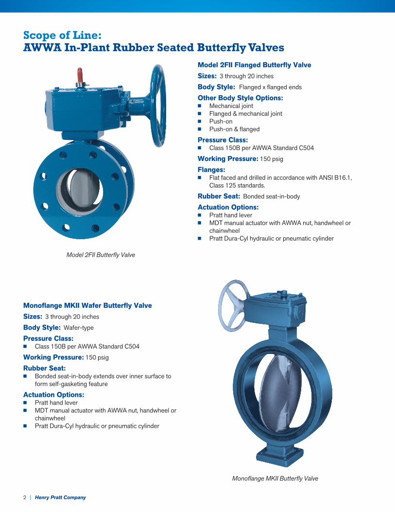
Model 2FII Flanged Butterfly ValveSizes: 3 through 20 inches
Body Style: Flanged x flanged ends
Other Body Style Options:n Mechanical jointn Flanged & mechanical jointn Push-onn Push-on & flanged
Pressure Class: n Class 150B per AWWA Standard C504
Working Pressure: 150 psig
Flanges: n Flat faced and drilled in accordance with ANSI B16.1,
Class 125 standards.
Rubber Seat: Bonded seat-in-body
Actuation Options:n Pratt hand levern MDT manual actuator with AWWA nut, handwheel or
chainwheel n Pratt Dura-Cyl hydraulic or pneumatic cylinder
Monoflange MKII Wafer Butterfly ValveSizes: 3 through 20 inches
Body Style: Wafer-type
Pressure Class: n Class 150B per AWWA Standard C504
Working Pressure: 150 psig
Rubber Seat: n Bonded seat-in-body extends over inner surface to
form self-gasketing feature
Actuation Options:n Pratt hand levern MDT manual actuator with AWWA nut, handwheel or
chainwheel n Pratt Dura-Cyl hydraulic or pneumatic cylinder
Scope of Line: AWWA In-Plant Rubber Seated Butterfly Valves
Monoflange MKII Butterfly Valve
Model 2FII Butterfly Valve
Henry Pratt Company | 3
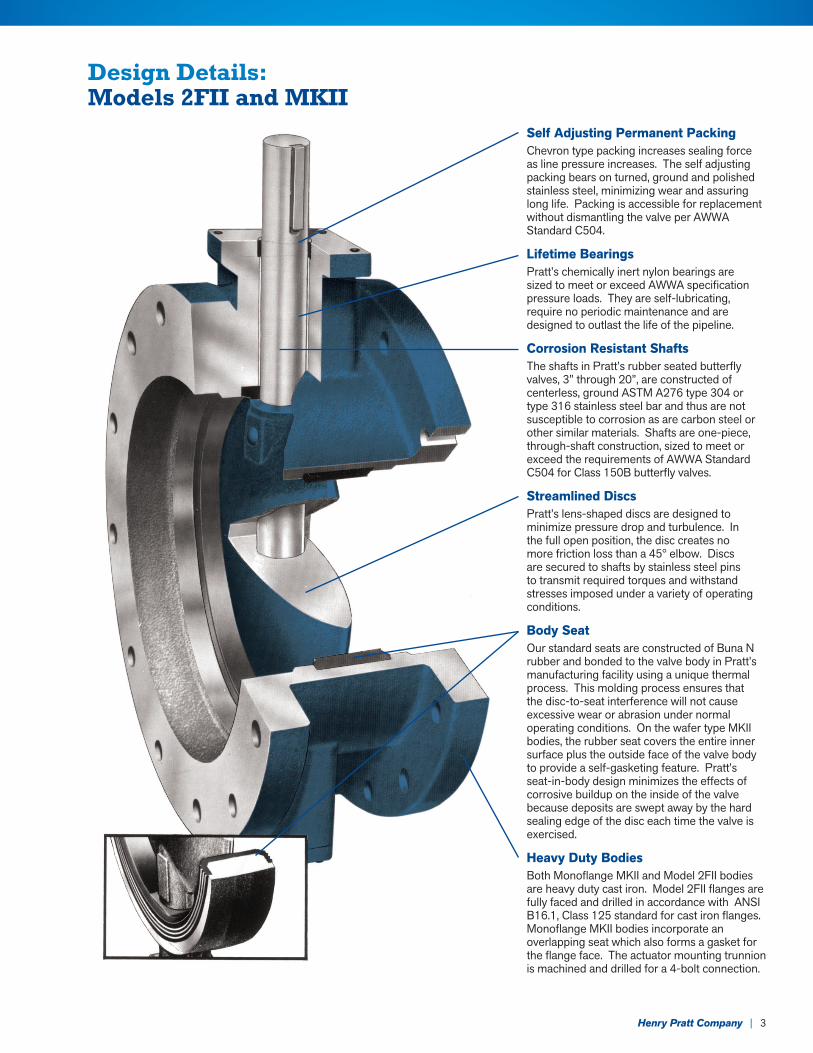
Design Details: Models 2FII and MKII
Self Adjusting Permanent PackingChevron type packing increases sealing force as line pressure increases. The self adjusting packing bears on turned, ground and polished stainless steel, minimizing wear and assuring long life. Packing is accessible for replacement without dismantling the valve per AWWA Standard C504.
Lifetime BearingsPratt’s chemically inert nylon bearings are sized to meet or exceed AWWA specification pressure loads. They are self-lubricating, require no periodic maintenance and are designed to outlast the life of the pipeline.
Corrosion Resistant ShaftsThe shafts in Pratt’s rubber seated butterfly valves, 3” through 20”, are constructed of centerless, ground ASTM A276 type 304 or type 316 stainless steel bar and thus are not susceptible to corrosion as are carbon steel or other similar materials. Shafts are one-piece, through-shaft construction, sized to meet or exceed the requirements of AWWA Standard C504 for Class 150B butterfly valves.
Streamlined DiscsPratt’s lens-shaped discs are designed to minimize pressure drop and turbulence. In the full open position, the disc creates no more friction loss than a 45° elbow. Discs are secured to shafts by stainless steel pins to transmit required torques and withstand stresses imposed under a variety of operating conditions.
Body SeatOur standard seats are constructed of Buna N rubber and bonded to the valve body in Pratt’s manufacturing facility using a unique thermal process. This molding process ensures that the disc-to-seat interference will not cause excessive wear or abrasion under normal operating conditions. On the wafer type MKII bodies, the rubber seat covers the entire inner surface plus the outside face of the valve body to provide a self-gasketing feature. Pratt’s seat-in-body design minimizes the effects of corrosive buildup on the inside of the valve because deposits are swept away by the hard sealing edge of the disc each time the valve is exercised.
Heavy Duty BodiesBoth Monoflange MKII and Model 2FII bodies are heavy duty cast iron. Model 2FII flanges are fully faced and drilled in accordance with ANSI B16.1, Class 125 standard for cast iron flanges. Monoflange MKII bodies incorporate an overlapping seat which also forms a gasket for the flange face. The actuator mounting trunnion is machined and drilled for a 4-bolt connection.
4 | Henry Pratt Company
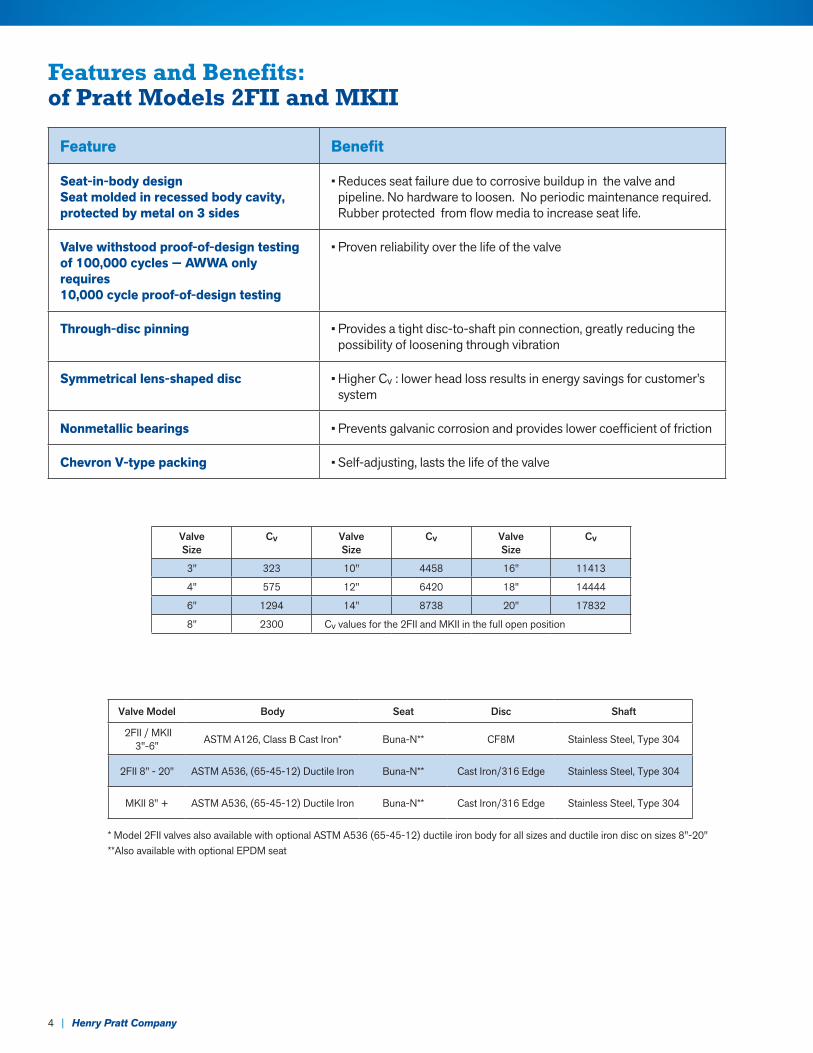
Features and Benefits: of Pratt Models 2FII and MKII
Feature Benefit
Seat-in-body design Seat molded in recessed body cavity, protected by metal on 3 sides
• Reduces seat failure due to corrosive buildup in the valve and pipeline. No hardware to loosen. No periodic maintenance required. Rubber protected from flow media to increase seat life.
Valve withstood proof-of-design testingof 100,000 cycles — AWWA only requires 10,000 cycle proof-of-design testing
• Proven reliability over the life of the valve
Through-disc pinning • Provides a tight disc-to-shaft pin connection, greatly reducing the possibility of loosening through vibration
Symmetrical lens-shaped disc • Higher Cv : lower head loss results in energy savings for customer’s system
Nonmetallic bearings • Prevents galvanic corrosion and provides lower coefficient of friction
Chevron V-type packing • Self-adjusting, lasts the life of the valve
Valve Size
Cv ValveSize
Cv ValveSize
Cv
3" 323 10" 4458 16" 11413
4" 575 12" 6420 18" 14444
6" 1294 14" 8738 20" 17832
8" 2300 Cv values for the 2FII and MKII in the full open position
Valve Model Body Seat Disc Shaft
2FII / MKII 3"-6" ASTM A126, Class B Cast Iron* Buna-N** CF8M Stainless Steel, Type 304
2FII 8" - 20" ASTM A536, (65-45-12) Ductile Iron Buna-N** Cast Iron/316 Edge Stainless Steel, Type 304
MKII 8" + ASTM A536, (65-45-12) Ductile Iron Buna-N** Cast Iron/316 Edge Stainless Steel, Type 304
* Model 2FII valves also available with optional ASTM A536 (65-45-12) ductile iron body for all sizes and ductile iron disc on sizes 8"-20"**Also available with optional EPDM seat
Henry Pratt Company | 5
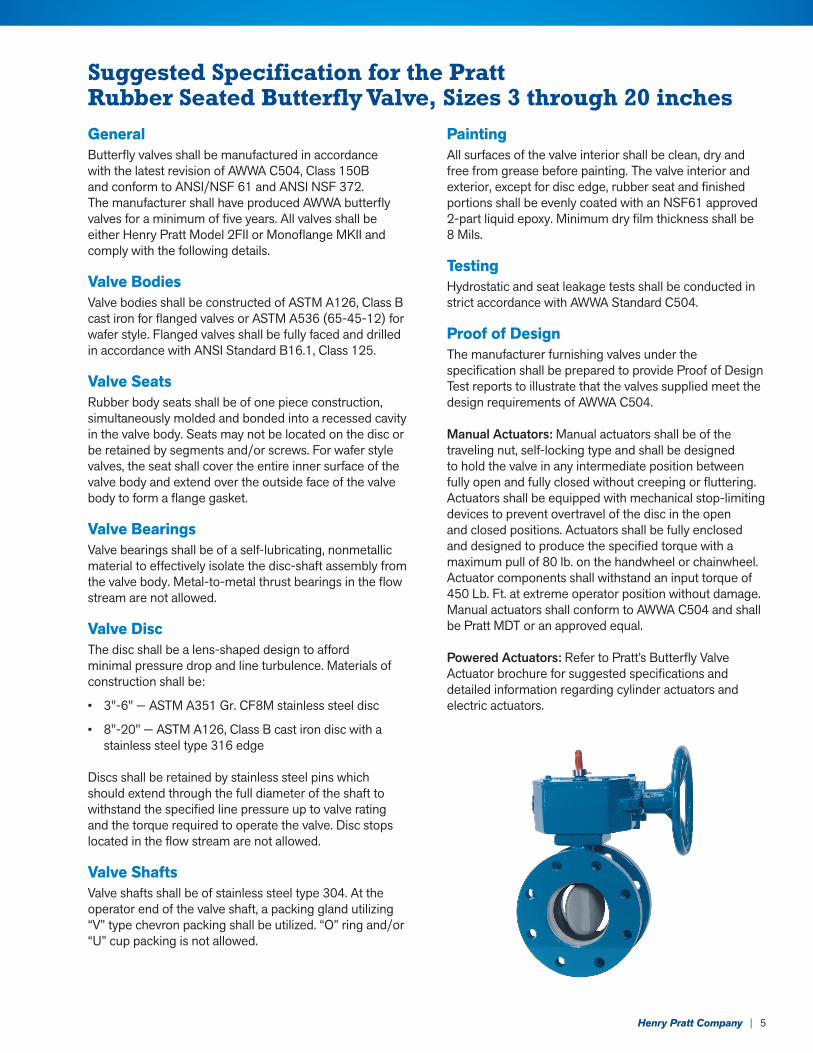
Suggested Specification for the Pratt Rubber Seated Butterfly Valve, Sizes 3 through 20 inchesGeneral Butterfly valves shall be manufactured in accordance with the latest revision of AWWA C504, Class 150B and conform to ANSI/NSF 61 and ANSI NSF 372. The manufacturer shall have produced AWWA butterfly valves for a minimum of five years. All valves shall be either Henry Pratt Model 2FII or Monoflange MKII and comply with the following details.
Valve BodiesValve bodies shall be constructed of ASTM A126, Class B cast iron for flanged valves or ASTM A536 (65-45-12) for wafer style. Flanged valves shall be fully faced and drilled in accordance with ANSI Standard B16.1, Class 125.
Valve SeatsRubber body seats shall be of one piece construction, simultaneously molded and bonded into a recessed cavity in the valve body. Seats may not be located on the disc or be retained by segments and/or screws. For wafer style valves, the seat shall cover the entire inner surface of the valve body and extend over the outside face of the valve body to form a flange gasket.
Valve BearingsValve bearings shall be of a self-lubricating, nonmetallic material to effectively isolate the disc-shaft assembly from the valve body. Metal-to-metal thrust bearings in the flow stream are not allowed.
Valve DiscThe disc shall be a lens-shaped design to afford minimal pressure drop and line turbulence. Materials of construction shall be:
• 3"-6" — ASTM A351 Gr. CF8M stainless steel disc
• 8"-20" — ASTM A126, Class B cast iron disc with a stainless steel type 316 edge
Discs shall be retained by stainless steel pins which should extend through the full diameter of the shaft to withstand the specified line pressure up to valve rating and the torque required to operate the valve. Disc stops located in the flow stream are not allowed.
Valve ShaftsValve shafts shall be of stainless steel type 304. At the operator end of the valve shaft, a packing gland utilizing “V” type chevron packing shall be utilized. “O” ring and/or “U” cup packing is not allowed.
PaintingAll surfaces of the valve interior shall be clean, dry and free from grease before painting. The valve interior and exterior, except for disc edge, rubber seat and finished portions shall be evenly coated with an NSF61 approved 2-part liquid epoxy. Minimum dry film thickness shall be 8 Mils.
TestingHydrostatic and seat leakage tests shall be conducted in strict accordance with AWWA Standard C504.
Proof of DesignThe manufacturer furnishing valves under the specification shall be prepared to provide Proof of Design Test reports to illustrate that the valves supplied meet the design requirements of AWWA C504.
Manual Actuators: Manual actuators shall be of the traveling nut, self-locking type and shall be designed to hold the valve in any intermediate position between fully open and fully closed without creeping or fluttering. Actuators shall be equipped with mechanical stop-limiting devices to prevent overtravel of the disc in the open and closed positions. Actuators shall be fully enclosed and designed to produce the specified torque with a maximum pull of 80 lb. on the handwheel or chainwheel. Actuator components shall withstand an input torque of 450 Lb. Ft. at extreme operator position without damage. Manual actuators shall conform to AWWA C504 and shall be Pratt MDT or an approved equal.
Powered Actuators: Refer to Pratt’s Butterfly Valve Actuator brochure for suggested specifications and detailed information regarding cylinder actuators and electric actuators.
6 | Henry Pratt Company
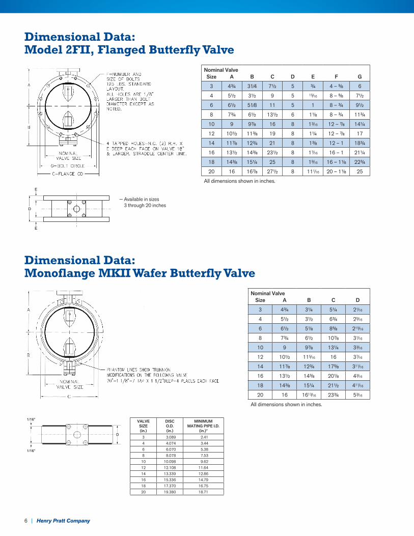
Dimensional Data: Model 2FII, Flanged Butterfly Valve
Dimensional Data: Monoflange MKII Wafer Butterfly Valve
— Available in sizes 3 through 20 inches
Nominal ValveSize A B C D E F G
3 43⁄4 31⁄4 71⁄2 5 3⁄4 4 – 5⁄8 6
4 51⁄2 31⁄2 9 5 15⁄16 8 – 5⁄8 71⁄2
6 61⁄2 51⁄8 11 5 1 8 – 3⁄4 91⁄2
8 73⁄4 61⁄2 131⁄2 6 11⁄8 8 – 3⁄4 113⁄4
10 9 97⁄8 16 8 13⁄16 12 – 7⁄8 141⁄4
12 101⁄2 113⁄8 19 8 11⁄4 12 – 7⁄8 17
14 117⁄8 123⁄4 21 8 13⁄8 12 – 1 183⁄4
16 131⁄2 143⁄8 231⁄2 8 17⁄16 16 – 1 211⁄4
18 143⁄8 151⁄4 25 8 19⁄16 16 – 11⁄8 223⁄4
20 16 167⁄8 271⁄2 8 111⁄16 20 – 11⁄8 25
All dimensions shown in inches.
D
E
E
D
1/16"
1/16"
VALVESIZE(in.)
DISCO.D.(in.)
MINIMUMMATING PIPE I.D.
(in.)*3 3.089 2.414 4.074 3.446 6.070 5.388 8.078 7.53
10 10.098 9.6212 12.108 11.6414 13.339 12.8616 15.336 14.7918 17.370 16.7520 19.380 18.71
Nominal ValveSize A B C D
3 43⁄4 31⁄4 51⁄4 21⁄16
4 51⁄2 31⁄2 63⁄4 25⁄16
6 61⁄2 51⁄8 85⁄8 215⁄16
8 73⁄4 61⁄2 107⁄8 31⁄16
10 9 97⁄8 131⁄4 33⁄16
12 101⁄2 115⁄16 16 37⁄16
14 117⁄8 123⁄4 175⁄8 311⁄16
16 131⁄2 143⁄8 201⁄8 43⁄16
18 143⁄8 151⁄4 211⁄2 411⁄16
20 16 1613⁄16 233⁄4 53⁄16
All dimensions shown in inches.
Henry Pratt Company | 7
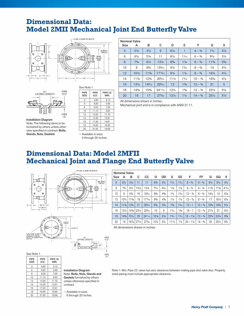
Dimensional Data: Model 2MII Mechanical Joint End Butterfly Valve
Dimensional Data: Model 2MFII Mechanical Joint and Flange End Butterfly Valve
Installation DiagramNote: The following items to be furnished by others unless other-wise specified in contract: Bolts, Glands, Nuts, Gaskets — Available in sizes
4 through 20 inches
See Note 1.
Installation DiagramNote: Bolts, Nuts, Glands and Gaskets furnished by others unless otherwise specified in contract.
Note 1: Min. Pipe I.D. value has zero clearance between mating pipe and valve disc. Properly sized piping must include appropriate clearance.
— Available in sizes 6 through 20 inches.
Nominal Valve Size A B C D E F G X
4 51⁄2 31⁄2 9 81⁄8 1 4 – 3⁄4 71⁄2 31⁄8
6 61⁄2 51⁄8 11 81⁄2 11⁄16 6 – 3⁄4 91⁄2 31⁄2
8 73⁄4 61⁄2 131⁄4 85⁄8 11⁄8 6 – 3⁄4 113⁄4 35⁄8
10 9 93⁄4 159⁄16 91⁄4 13⁄16 8 – 3⁄4 14 41⁄4
12 101⁄2 113⁄8 1715⁄16 91⁄4 11⁄4 8 – 3⁄4 161⁄4 41⁄4
14 117⁄8 123⁄4 205⁄16 111⁄2 15⁄16 10 – 3⁄4 183⁄4 41⁄2
16 131⁄2 145⁄16 229⁄16 12 13⁄8 12 – 3⁄4 21 5
18 143⁄8 153⁄8 2411⁄16 121⁄4 13⁄8 12 – 3⁄4 231⁄4 51⁄4
20 16 17 273⁄32 121⁄2 11⁄2 14 – 3⁄4 251⁄2 51⁄2
All dimensions shown in inches.Mechanical joint end is in compliance with ANSI 21.11.
Nominal ValveSize A B C CC D DD E EE F FF G GG X
6 61⁄2 51⁄8 11 11 63⁄4 41⁄4 11⁄16 11⁄16 8 – 3⁄4 6 – 3⁄4 91⁄2 91⁄2 41⁄4
8 73⁄4 61⁄2 131⁄2 131⁄4 75⁄16 45⁄16 11⁄8 11⁄8 8 – 3⁄4 6 – 3⁄4 113⁄4 113⁄4 413⁄16
10 9 97⁄8 16 159⁄16 85⁄8 45⁄8 11⁄4 13⁄16 12 – 7⁄8 8 – 3⁄4 141⁄4 14 61⁄8
12 101⁄2 113⁄8 19 1715⁄16 85⁄8 45⁄8 11⁄4 11⁄4 12 – 7⁄8 8 – 3⁄4 17 161⁄4 61⁄8
14 117⁄8 123⁄4 21 205⁄16 93⁄4 53⁄4 13⁄8 15⁄16 12 – 1 10 – 3⁄4 183⁄4 183⁄4 61⁄4
16 131⁄2 143⁄8 231⁄2 229⁄16 10 6 17⁄16 13⁄8 16 – 1 12 – 3⁄4 211⁄4 21 61⁄2
18 143⁄8 151⁄4 25 2411⁄16 101⁄8 61⁄8 19⁄16 17⁄16 16 – 11⁄8 12 – 3⁄4 223⁄4 231⁄4 65⁄8
20 16 167⁄8 271⁄2 273⁄32 101⁄4 61⁄4 111⁄16 11⁄2 20 – 11⁄8 14 – 3⁄4 25 251⁄2 63⁄4
All dimensions shown in inches.
F=NO. & SIZE OF BOLTS
G=BOLTCIRCLE
NOM.VALVESIZE
D A BE E
C
R
X=LAYING LENGTH
PIPEI.D.
PIPEO.D.
X=LAYING LENGTH
E
FF=NO. & SIZE OF BOLTS
GG=BOLTCIRCLE
NOM.VALVESIZE
EE
CC
G=BOLTCIRCLE
C = FLANGE OD
F=NO. & SIZE OF BOLTS125 LB. ST'D. LAYOUTSTRADDLE C'LINE ALL HOLES 1/8" LARGER THANBOLT DIA.
DA BDD
PIPEI.D.
PIPEO.D.
X=LAYING LENGTH
E
FF=NO. & SIZE OF BOLTS
GG=BOLTCIRCLE
NOM.VALVESIZE
EE
CC
G=BOLTCIRCLE
C = FLANGE OD
F=NO. & SIZE OF BOLTS125 LB. ST'D. LAYOUTSTRADDLE C'LINE ALL HOLES 1/8" LARGER THANBOLT DIA.
DA BDD
PIPEI.D.
PIPEO.D.
PIPESIZE
PIPEO.D.
PIPE I.D.MIN.
4 4.80 3.106 6.90 5.698 9.05 7.65
10 11.10 9.9312 13.20 11.7014 15.30 12.9116 17.40 14.9118 19.50 16.9520 21.60 18.96
PIPESIZE
PIPEO.D.
PIPE I.D.MIN.
4 4.80 3.106 6.90 5.698 9.05 7.65
10 11.10 9.9312 13.20 11.7014 15.30 12.9116 17.40 14.9118 19.50 16.9520 21.60 18.96
X=LAYING LENGTH
E
FF=NO. & SIZE OF BOLTS
GG=BOLTCIRCLE
NOM.VALVESIZE
EE
CC
G=BOLTCIRCLE
C = FLANGE OD
F=NO. & SIZE OF BOLTS125 LB. ST'D. LAYOUTSTRADDLE C'LINE ALL HOLES 1/8" LARGER THANBOLT DIA.
DA BDD
PIPEI.D.
PIPEO.D.
See Note 1.
8 | Henry Pratt Company
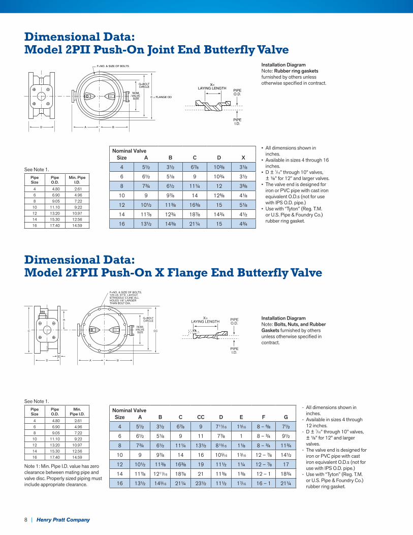
Dimensional Data: Model 2PII Push-On Joint End Butterfly Valve
Dimensional Data: Model 2FPII Push-On X Flange End Butterfly Valve
See Note 1.
See Note 1.
PipeSize
PipeO.D.
Min. PipeI.D.
4 4.80 2.616 6.90 4.968 9.05 7.22
10 11.10 9.2212 13.20 10.9714 15.30 12.5616 17.40 14.59
• All dimensions shown in inches.
• Available in sizes 4 through 16 inches.
• D ± 1⁄16" through 10" valves, ± 1⁄8" for 12" and larger valves.
• The valve end is designed for iron or PVC pipe with cast iron equivalent O.D.s (not for use with IPS O.D. pipe.)
• Use with “Tyton” (Reg. T.M. or U.S. Pipe & Foundry Co.) rubber ring gasket.
- All dimensions shown in inches.
- Available in sizes 4 through 12 inches.
- D ± 1⁄16" through 10" valves, ± 1⁄8" for 12" and larger valves.
- The valve end is designed for iron or PVC pipe with cast iron equivalent O.D.s (not for use with IPS O.D. pipe.)
- Use with “Tyton” (Reg. T.M. or U.S. Pipe & Foundry Co.) rubber ring gasket.
Installation DiagramNote: Rubber ring gaskets furnished by others unless otherwise specified in contract.
Installation DiagramNote: Bolts, Nuts, and Rubber Gaskets furnished by others unless otherwise specified in contract.
Nominal ValveSize A B C D X
4 51⁄2 31⁄2 67⁄8 103⁄8 31⁄8
6 61⁄2 51⁄8 9 103⁄4 31⁄2
8 73⁄4 61⁄2 111⁄4 12 35⁄8
10 9 97⁄8 14 125⁄8 41⁄8
12 101⁄2 113⁄8 163⁄8 15 51⁄8
14 117⁄8 123⁄4 187⁄8 143⁄4 41⁄2
16 131⁄2 143⁄8 211⁄4 15 43⁄4
PipeSize
PipeO.D.
Min.Pipe I.D.
4 4.80 2.616 6.90 4.968 9.05 7.22
10 11.10 9.2212 13.20 10.9714 15.30 12.5616 17.40 14.59
Note 1: Min. Pipe I.D. value has zero clearance between mating pipe and valve disc. Properly sized piping must include appropriate clearance.
Nominal ValveSize A B C CC D E F G
4 51⁄2 31⁄2 67⁄8 9 711⁄16 15⁄16 8 – 5⁄8 71⁄2
6 61⁄2 51⁄8 9 11 77⁄8 1 8 – 3⁄4 91⁄2
8 73⁄4 61⁄2 111⁄4 131⁄2 815⁄16 11⁄8 8 – 3⁄4 113⁄4
10 9 97⁄8 14 16 105⁄16 13⁄16 12 – 7⁄8 141⁄2
12 101⁄2 113⁄8 163⁄8 19 111⁄2 11⁄4 12 – 7⁄8 17
14 117⁄8 1211⁄16 187⁄8 21 113⁄8 13⁄8 12 – 1 183⁄4
16 131⁄2 145⁄16 211⁄4 231⁄2 111⁄2 17⁄16 16 – 1 211⁄4
X=LAYING LENGTH
PIPEO.D.
PIPEI.D.
F=NO. & SIZE OF BOLTS
G=BOLTCIRCLE
NOM.VALVESIZE
D A B
C = FLANGE OD
X=LAYING LENGTH
PIPEO.D.
PIPEI.D.
F=NO. & SIZE OF BOLTS
G=BOLTCIRCLE
NOM.VALVESIZE
D A B
C = FLANGE OD
X= LAYING LENGTH PIPE
O.D.
PIPE I.D.
F=NO. & SIZE OF BOLTS. 125 LB. ST'D. LAYOUT. STRADDLE C'LINE ALL HOLES 1/8" LARGER THAN BOLT DIA.
G=BOLT CIRCLE
NOM. VALVE SIZE
D A B E
CC
R
C
X= LAYING LENGTH PIPE
O.D.
PIPE I.D.
F=NO. & SIZE OF BOLTS. 125 LB. ST'D. LAYOUT. STRADDLE C'LINE ALL HOLES 1/8" LARGER THAN BOLT DIA.
G=BOLT CIRCLE
NOM. VALVE SIZE
D A B E
CC
R
C
Henry Pratt Company | 9
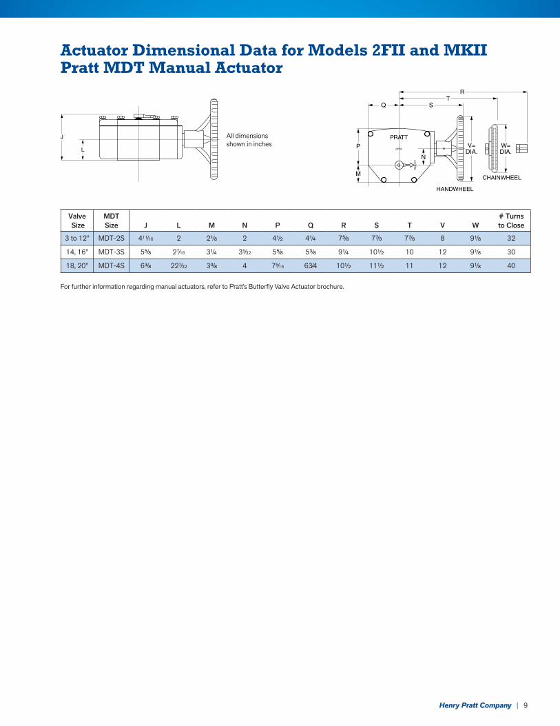
Actuator Dimensional Data for Models 2FII and MKIIPratt MDT Manual Actuator
All di men sions shown in inches
For further information regarding manual actuators, refer to Pratt’s Butterfly Valve Actuator brochure.
Valve Size
MDTSize
J
L
M
N
P
Q
R
S
T
V
W
# Turns to Close
3 to 12" MDT-2S 411⁄16 2 21⁄8 2 41⁄2 41⁄4 75⁄8 77⁄8 77⁄8 8 91⁄8 32
14, 16" MDT-3S 55⁄8 27⁄16 31⁄4 35⁄32 55⁄8 53⁄8 91⁄4 101⁄2 10 12 91⁄8 30
18, 20" MDT-4S 63⁄8 227⁄32 33⁄8 4 75⁄16 63⁄4 101⁄2 111⁄2 11 12 91⁄8 40
J
LC
LOS
ED
OPEN
PRATT
P
M
N
Q ST
R
V=DIA.
HANDWHEEL
CHAINWHEEL
W=DIA.
©2016 Henry Pratt Company | Printed in the U.S.A. | Form 13086 4/2016
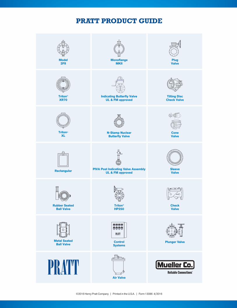
PRATT PRODUCT GUIDE
Model 2FII
Monoflange MKII
PlugValve
Triton® XR70
Indicating Butterfly ValveUL & FM approved
Tilting Disc Check Valve
Triton® XL
N-Stamp Nuclear Butterfly Valve
Cone Valve
Rectangular PIVA Post Indicating Valve AssemblyUL & FM approved
Sleeve Valve
Rubber SeatedBall Valve
Triton® HP250
Check Valve
Metal SeatedBall Valve
ControlSystems
Plunger Valve
Air Valve


![INDEX [] · and AWWA check valves. These operators are assured of durability, along with an ease of maintenance, for trouble free production. Walworth Water Works AWWA Butterfly and](https://img.pdfslide.net/doc/110x75/5e6179fdef074b09e5529c86/index-and-awwa-check-valves-these-operators-are-assured-of-durability-along.jpg)