Embed Size (px)
Citation preview

energies
Article
Axial Flux PM In-Wheel Motor for Electric Vehicles:3D Multiphysics Analysis
Andrea Credo 1,* , Marco Tursini 1 , Marco Villani 1, Claudia Di Lodovico 2 , Michele Orlando 2
and Federico Frattari 2
Citation: Credo, A.; Tursini, M.;
Villani, M.; Di Lodovico, C.; Orlando,
M.; Frattari, F. Axial Flux PM
in-Wheel Motor for Electric Vehicles:
3D Multiphysics Analysis. Energies
2021, 14, 2107. https://doi.org/
10.3390/en14082107
Academic Editor: Chunhua Liu
Received: 11 February 2021
Accepted: 5 April 2021
Published: 9 April 2021
Publisher’s Note: MDPI stays neutral
with regard to jurisdictional claims in
published maps and institutional affil-
iations.
Copyright: © 2021 by the authors.
Licensee MDPI, Basel, Switzerland.
This article is an open access article
distributed under the terms and
conditions of the Creative Commons
Attribution (CC BY) license (https://
creativecommons.org/licenses/by/
4.0/).
1 Department of Industrial and Information Engineering and Economics, University of L’Aquila,Monteluco di Roio, 67100 L’Aquila, AQ, Italy; [email protected] (M.T.); [email protected] (M.V.)
2 Spin Applicazioni Magnetiche Srl, Via F. Corselli n. 11, 29122 Piacenza, PC, Italy;[email protected] (C.D.L.); [email protected] (M.O.);[email protected] (F.F.)
* Correspondence: [email protected]; Tel.: +39-0862434428
Abstract: The Axial Flux Permanent Magnet (AFPM) motor represents a valid alternative to thetraditional radial flux motor due to its compact structure; it is suitable for in-wheel applications so thatthe transmission gear can be suppressed. The modeling of the motor is a purely Three-Dimensional(3D) problem and the use of 3D finite element tools allows the attainment of accurate results takingalso into account the effects of the end-windings. Moreover, a 3D multiphysics analysis is essentialto evaluate not only the motor performance and its thermal behavior, but also the electromagneticforces acting on the surfaces of the stator teeth and of the magnets that face the air gap. Moreover, asthe vehicle’s motors often work in variable-speed conditions, the prediction of vibrations and noisefor electric motors over a wide speed range is usually necessary. The paper presents a double-sidedAFPM motor for a small pure electric vehicle; the basic drive architecture includes four axial fluxmotors installed directly inside the vehicle’s wheels. The aim is to propose advanced and integratedelectromagnetic, vibroacoustic and thermal analyses that allow the investigation of the axial fluxmotor behavior in a detailed and exhaustive way.
Keywords: axial flux; permanent magnet; in-wheel; electric vehicle; direct-drive; multiphysics;thermal; vibration; noise; 3D finite element analysis
1. Introduction
The electric mobility represents a possible solution to the pollution and global warmingproblems. The research on these topics is intense and there is a great interest in findinginnovative and more efficient solutions for the main component of the powertrain: theelectric motor. Nowadays, the types of electric motors for automotive applications thatare most frequently adopted are radial flux machines, either squirrel cage induction orPermanent Magnet (PM) ones, but innovative motor typologies are being proposed andinvestigated to guarantee a high efficiency and high torque and power densities [1].
The current Electric Vehicles (EV) can be classified into two categories according totheir configurations, namely “indirect-drive” and “direct-drive”.
The first solution needs the reduction gear and the differential gear and presentsmechanical losses during the power transmission from the motor to the car’s tires.
On the other hand, the direct-drive electric vehicle is simpler because it does notrequire transmission components and allows to reduce the volume and the weight ofthe whole system while improving its efficiency [2,3]: it could be the future trend forthe new EVs. For this specific application, the Axial Flux Permanent Magnet (AFPM)motor represents a valid alternative to the traditional radial flux motor due to its compactstructure; it can also be suitable to be placed inside the wheel so that the transmission gear
Energies 2021, 14, 2107. https://doi.org/10.3390/en14082107 https://www.mdpi.com/journal/energies

Energies 2021, 14, 2107 2 of 18
is suppressed [4–6]. In [7], a prototype of an AFPM motor has been realized, tested andcompared to a radial flux motor.
Due to the integration of the reducer with the motor, the heat dissipation, lubrication,protection, and torque output capacity of the in-wheel motor system can be significantlyimproved.
In this paper, a small pure electric vehicle with gearless in-wheel motors was consid-ered as a case study; the basic drive architecture is shown in Figure 1. The drive systemincludes four axial flux PM synchronous motors and four motor drive controllers, each ofwhich is composed of a three-phase inverter. As the motor directly drives the wheel, theaxial length of the motor itself must be small and its diameter could be relatively large;furthermore, the motor has to be designed as a high-torque low-speed motor.
Figure 1. The direct-drive electric vehicle with in-wheel motors.
The modeling of an axial flux machine is a pure 3D problem and the use of 3DFinite Element (FE) tools [8–10] allows the attainment of accurate results taking alsointo account the effects of the end-windings. Moreover, a 3D multiphysics analysis isessential to evaluate not only the motor performance, but also its thermal behavior andthe electromagnetic forces acting on the surfaces of the stator teeth and of the magnets.Moreover, since the vehicle’s motors often work in variable-speed conditions, the predictionof vibrations and noise for electric motors over a wide speed range is usually necessary [11].
This paper is organized as follows: the design of the AFPM in-wheel motor is illus-trated in Section 2 together with the criteria used for the choice of the number of poles andslots; then, a case study is proposed in Section 3. In Section 4, the multiphysics analysis ispresented in order to predict the performance, the temperatures and the electromagneticvibration and noise of the axial flux PM motor. Finally, the conclusions are drawn inSection 5.
2. The AFPM Motor Sizing Equations
The AFPM motors can be designed in single-sided or double-sided configurations andas single-stage or multi-stage machines [12–14]. In the case of a double-sided configuration(Figure 2), the motor has two rotor discs with surface Permanent Magnets (PMs) anda central stator core that is sandwiched between the rotor discs (Figure 2). The slottedstator core is manufactured from laminated electrical steel and has two sets of three-phasewindings: Figure 3 shows the prototype of a laminated stator core. A low-cost processforesees the stator slot cutting; however, this process gives rise to the short-circuit of thelamination sheets and to a slight increase in the iron losses. To avoid this drawback, the“slinky technology” can be used: the lamination strip is carefully punched and then woundto realize the stator core.
The PMs are glued to the surfaces of the solid mild-steel rotor discs. The flux in theAFPM motor flows axially through the air gap.
The numbers of slots and poles have to be chosen so that their ratio is fractional and,using concentrated windings, it is possible to reduce the cogging torque and to improve themachine performance. The AFPM machine with fractional-slot concentrated windings [8],compared to the traditional distributed winding one, offers many advantages: shorterend-turns, reduced copper losses and a higher slot fill factor.
Energies 2021, 14, 2107 3 of 18
Figure 2. The double-sided axial flux permanent magnet motor.
Figure 3. The prototype of a laminated stator core.
Several authors propose a criterion for the choice of the right N. poles-N. slots com-bination. In [5], the authors suggest to reduce the cogging torque using fractional-slotwindings and magnetic wedges in the slots. Fractional-slot windings with a number of slotsper pole and per phase less than unity sometimes become mandatory for the construction oflow-power machines with a large number of pole pairs. A fractional-slot winding typicallyexhibits an inductance higher than the corresponding integer-slot winding configuration.In [6], the authors point out that the choice of a high number of rotor poles allows thereduction of the mass; however, the thickness of the magnetic air gap must be small com-pared to the pole pitch in order to reduce the leakage flux. In [4], the authors remark thatthe appropriate selection of the number of poles is important to realize a small-sized motor.A low number of poles would lead to the increase in the axial length since the size of eachPM would have to be greater, resulting in a thicker rotor yoke; the radial size of the motorwould also be greater and the leakage inductance and copper losses would increase. Onthe other hand, if the number of poles was high, the frequency would be higher and theiron losses would increase. In the AFPM motor, the pole width wp(r) and the pole pitchτ(r) are functions of the axial flux machine radius r:
τ(r) =2π r2p
=π rp
(1)
and
βi =wp(r)τ(r)
(2)
where p is the number of pole pairs.
Energies 2021, 14, 2107 4 of 18
The linear current density is also a function of the radius and its peak value for athree-phase machine is equal to:
Amax =3√
2 Nt Iph
p τ(r)=
3√
2 Nt Iph
π r(3)
where Nt is the number of turns in series per phase and Iph is the phase current.It is convenient to introduce the inner-to-outer PM diameter ratio:
kD =DiDo
(4)
The average electromagnetic torque for a three-phase double-sided machine is givenby the following equation:
T = 2π Bavg Arms R3o
(kD − k3
D
)(5)
where Bavg is the average value of the air gap flux density and Arms is the rms value of theline current density.
In most axial flux machines, the kD ratio is a major design parameter, which hassignificant effects on the characteristics of the machine and, therefore, must be carefullychosen; this aspect has been fully investigated in [15], where the kD value for high torquedensity AFPM motors should be in the range 0.4–0.5. The paper analyzes also the “ratiobetween the axial length and the outer diameter of the whole machine”, which representshow flat the motor is: when this ratio has a small value, the torque and the torque densityof the AFPM motor will be higher.
3. A Case Study
The AFPM motor was designed for a small pure electric vehicle without reductiongears: the basic drive architecture includes four axial flux motors installed directly insidethe vehicle’s wheels (Figure 1). The requirements of the AFPM motor are listed in Table 1.Due to the limited space inside the wheel, the AFPM motor should guarantee a high torquedensity; this goal has been achieved with a double-sided AFPM motor with a double airgap and whose stator core is sandwiched between two rotor plates.
Table 1. AFPM motor requirements.
Requirement Unit Value
DC voltage V 550Maximum phase current A <30
Base speed rpm 840Torque @ base speed Nm >75
Efficiency % >80Maximum speed rpm 1200
Torque @ maximum speed Nm >60Maximum outer diameter mm <200
Maximum axial length mm <80Winding temperature C 100
Cooling system Forced-air
The sizing procedure proposed in [12] has been adopted by means of a spreadsheetsoftware. The first part of the design procedure consisted of the choice of the rotor poleand of the stator slot numbers: for this purpose, different combinations have been testedand the following solution has been adopted: 18 stator slots and 16 rotor poles, single layer,fractional slot and concentrated windings (alternate type).
Energies 2021, 14, 2107 5 of 18
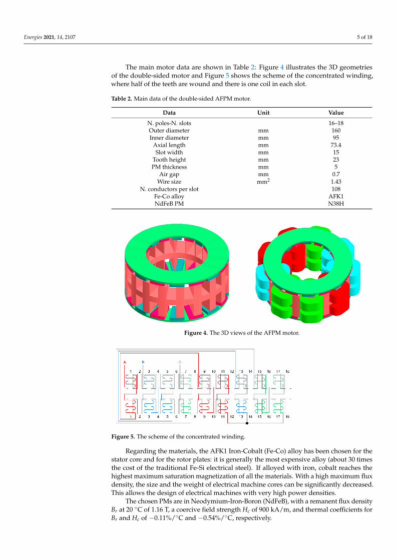
The main motor data are shown in Table 2: Figure 4 illustrates the 3D geometriesof the double-sided motor and Figure 5 shows the scheme of the concentrated winding,where half of the teeth are wound and there is one coil in each slot.
Table 2. Main data of the double-sided AFPM motor.
Data Unit Value
N. poles-N. slots 16–18Outer diameter mm 160Inner diameter mm 95
Axial length mm 73.4Slot width mm 15
Tooth height mm 23PM thickness mm 5
Air gap mm 0.7Wire size mm2 1.43
N. conductors per slot 108Fe-Co alloy AFK1NdFeB PM N38H
Figure 4. The 3D views of the AFPM motor.
Figure 5. The scheme of the concentrated winding.
Regarding the materials, the AFK1 Iron-Cobalt (Fe-Co) alloy has been chosen for thestator core and for the rotor plates: it is generally the most expensive alloy (about 30 timesthe cost of the traditional Fe-Si electrical steel). If alloyed with iron, cobalt reaches thehighest maximum saturation magnetization of all the materials. With a high maximum fluxdensity, the size and the weight of electrical machine cores can be significantly decreased.This allows the design of electrical machines with very high power densities.
The chosen PMs are in Neodymium-Iron-Boron (NdFeB), with a remanent flux densityBr at 20 C of 1.16 T, a coercive field strength Hc of 900 kA/m, and thermal coefficients forBr and Hc of −0.11%/C and −0.54%/C, respectively.

Energies 2021, 14, 2107 6 of 18
4. The 3D Multiphysics Analysis
The components of the AFPM motor vary with its radius and this makes the analysismore complicated: thus, 3D FE analyses have been conducted through the Altair tools.Particularly, a 3D multiphysics analysis allowed the evaluation of not only the motorperformance, but also the thermal behavior and the electromagnetic forces acting on thesurfaces of the stator teeth and of the permanent magnets.
4.1. Electromagnetic Analyses
3D electromagnetic analyses have been carried out in order to evaluate the perfor-mance of the AFPM motor and its magnetic field distribution: static analyses have beenperformed to shorten the simulation time. A temperature of 100 C has been imposed forboth the stator windings and the permanent magnets.
Table 3 lists the motor performance at base speed and at maximum speed, and it fullysatisfies the initial requirements with an efficiency higher than 80%.
Table 3. Motor performance.
Requirement Unit Value
DC voltage V 550Winding temperature C 100
PM temperature C 100Phase resistance Ω 0.85
Phase current A 28Base speed rpm 840
Torque @ base speed Nm 78Power @ base speed kW 6.86
Efficiency % 85Max speed rpm 1200
Torque @ max speed Nm 67.5Power @ max speed kW 8.48
The Back ElectroMotive Force (BEMF) at no-load is shown in Figure 6 and it exhibits asinusoidal behavior, while Figure 7 presents the motor torque profile: the ripple, calculatedas the ratio of the difference between the maximum and the minimum torque values to theaverage one, is very low and this is mainly due to the use of concentrated windings and tothe right choice of the combination N. poles-N. slots.
Figure 6. The back electromotive force at no-load.
Energies 2021, 14, 2107 7 of 18
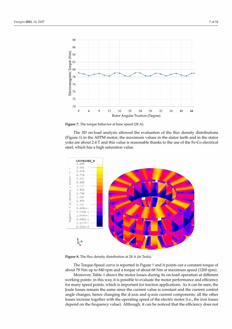
Figure 7. The torque behavior at base speed (28 A).
The 3D on-load analysis allowed the evaluation of the flux density distributions(Figure 8) in the AFPM motor; the maximum values in the stator teeth and in the statoryoke are about 2.4 T and this value is reasonable thanks to the use of the Fe-Co electricalsteel, which has a high saturation value.
Figure 8. The flux density distribution at 28 A (in Tesla).
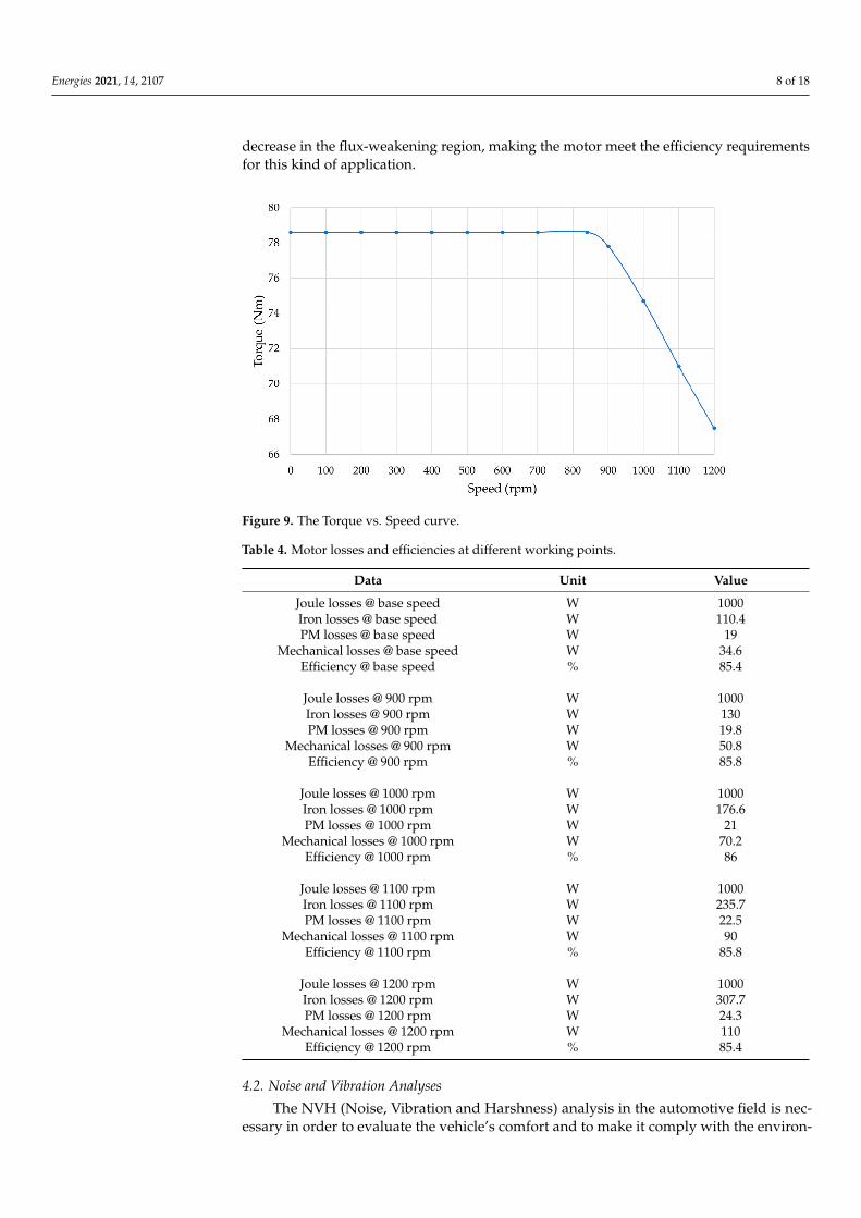
The Torque-Speed curve is reported in Figure 9 and it points out a constant torque ofabout 78 Nm up to 840 rpm and a torque of about 68 Nm at maximum speed (1200 rpm).
Moreover, Table 4 shows the motor losses during its on-load operation at differentworking points: in this way, it is possible to evaluate the motor performance and efficiencyfor many speed points, which is important for traction applications. As it can be seen, theJoule losses remain the same since the current value is constant and the current controlangle changes, hence changing the d-axis and q-axis current components; all the otherlosses increase together with the operating speed of the electric motor (i.e., the iron lossesdepend on the frequency value). Although, it can be noticed that the efficiency does not
Energies 2021, 14, 2107 8 of 18
decrease in the flux-weakening region, making the motor meet the efficiency requirementsfor this kind of application.
Figure 9. The Torque vs. Speed curve.
Table 4. Motor losses and efficiencies at different working points.
Data Unit Value
Joule losses @ base speed W 1000Iron losses @ base speed W 110.4PM losses @ base speed W 19
Mechanical losses @ base speed W 34.6Efficiency @ base speed % 85.4
Joule losses @ 900 rpm W 1000Iron losses @ 900 rpm W 130PM losses @ 900 rpm W 19.8
Mechanical losses @ 900 rpm W 50.8Efficiency @ 900 rpm % 85.8
Joule losses @ 1000 rpm W 1000Iron losses @ 1000 rpm W 176.6PM losses @ 1000 rpm W 21
Mechanical losses @ 1000 rpm W 70.2Efficiency @ 1000 rpm % 86
Joule losses @ 1100 rpm W 1000Iron losses @ 1100 rpm W 235.7PM losses @ 1100 rpm W 22.5
Mechanical losses @ 1100 rpm W 90Efficiency @ 1100 rpm % 85.8
Joule losses @ 1200 rpm W 1000Iron losses @ 1200 rpm W 307.7PM losses @ 1200 rpm W 24.3
Mechanical losses @ 1200 rpm W 110Efficiency @ 1200 rpm % 85.4
4.2. Noise and Vibration Analyses
The NVH (Noise, Vibration and Harshness) analysis in the automotive field is nec-essary in order to evaluate the vehicle’s comfort and to make it comply with the environ-

Energies 2021, 14, 2107 9 of 18
mental requirements, since the motor can be a great source of noise and vibrations if notproperly designed and controlled [16]. The reason why the electric motor can producenoise has to be found in the magnetic forces acting between the stator teeth and the rotorpermanent magnets [17,18].
Three main categories of vibrations and noise produced by an electrical machine canbe defined: the electromagnetic vibrations and noise (due to higher harmonics of timeand space, phase unbalance, magnetic saturation, slot openings, magnetostriction, etc.),the mechanical ones (due to bearings, rotor unbalance, shaft misalignment, etc.) and theaerodynamic ones (due to the air flow produced by the cooling fan, etc.).
In particular, in this case study, the modal analysis of the electrical machine’s mechan-ical system (complete with housing and shaft) and the frequency response on a modalbasis have been carried out. The first analysis has provided the natural frequencies and themode shapes of the mechanical structure, in order to check if any frequency of the Maxwellforces between the stator and the rotor matched them, either spatially and temporally: thiswould cause the so-called resonance phenomenon, a dynamic effect that amplifies noiseand vibrations, making them dangerous for the motor’s integrity.
In order to carry out a realistic vibroacoustic analysis and to obtain accurate results,the machine’s geometry used for the electromagnetic analyses must be mirrored first andthen completed with the addition of the shaft and of the housing. The mechanical systemof the axial flux permanent magnet machine is shown in Figure 10. It is possible to see thesecond-order tetrahedral mesh that has been created after many attempts at finding theproper element size for each component; in fact, the mesh elements have to be small enoughto obtain accurate results but not too much to excessively increase the computational time.
Figure 10. The meshed mechanical model of the AFPM machine.
The modal and frequency response analyses have been realized with another FiniteElement Analysis (FEA) tool of the Altair Suite: HyperWorks. After defining the mechanicalproperties of each component’s material (Table 5), the entities that define the bearings,which connect the shaft to the housing, and the flanges, which connect the rotor discs to theshaft, have been created. Moreover, the contacts between the stator teeth and the windingsand between the stator teeth and the housing have been defined and the clamped-conditionfor one side of the housing has been set.
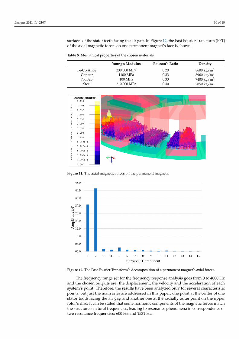
Finally, the electromagnetic torque and the normal component of the global magneticforces due to the stator-PMs interaction (while in Figure 11 the nodal magnetic forces areshown) have been exported from Altair Flux and imported into HyperWorks as loads ofthe studied mechanical system: specifically, the global Maxwell forces have been appliedto both the surface sets of the rotor permanent magnets and of the stator teeth facing eachother, while the electromagnetic torque has been applied as a distributed load to all the
Energies 2021, 14, 2107 10 of 18
surfaces of the stator teeth facing the air gap. In Figure 12, the Fast Fourier Transform (FFT)of the axial magnetic forces on one permanent magnet’s face is shown.
Table 5. Mechanical properties of the chosen materials.
Young’s Modulus Poisson’s Ratio Density
Fe-Co Alloy 230,000 MPa 0.29 8600 kg/m3
Copper 1100 MPa 0.33 8960 kg/m3
NdFeB 100 MPa 0.33 7400 kg/m3
Steel 210,000 MPa 0.30 7850 kg/m3
Figure 11. The axial magnetic forces on the permanent magnets.
Figure 12. The Fast Fourier Transform’s decomposition of a permanent magnet’s axial forces.
The frequency range set for the frequency response analysis goes from 0 to 4000 Hzand the chosen outputs are: the displacement, the velocity and the acceleration of eachsystem’s point. Therefore, the results have been analyzed only for several characteristicpoints, but just the main ones are addressed in this paper: one point at the center of onestator tooth facing the air gap and another one at the radially outer point on the upperrotor’s disc. It can be stated that some harmonic components of the magnetic forces matchthe structure’s natural frequencies, leading to resonance phenomena in correspondence oftwo resonance frequencies: 600 Hz and 1531 Hz.
Energies 2021, 14, 2107 11 of 18
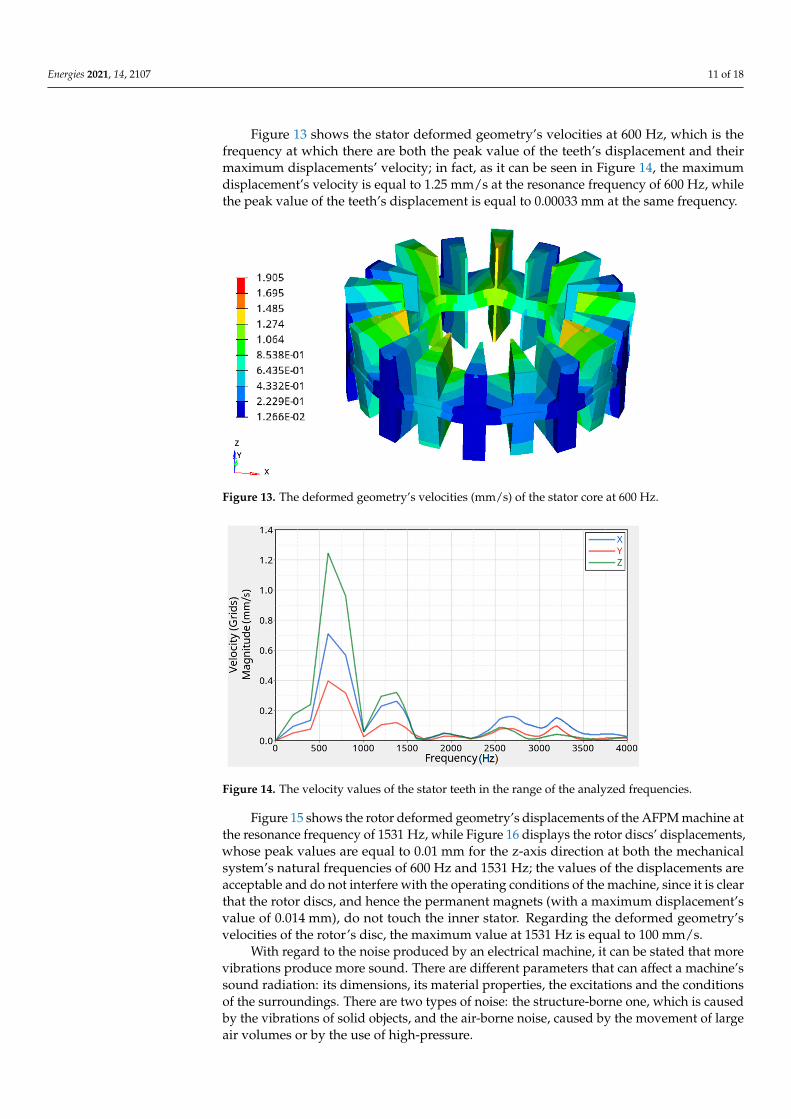
Figure 13 shows the stator deformed geometry’s velocities at 600 Hz, which is thefrequency at which there are both the peak value of the teeth’s displacement and theirmaximum displacements’ velocity; in fact, as it can be seen in Figure 14, the maximumdisplacement’s velocity is equal to 1.25 mm/s at the resonance frequency of 600 Hz, whilethe peak value of the teeth’s displacement is equal to 0.00033 mm at the same frequency.
Figure 13. The deformed geometry’s velocities (mm/s) of the stator core at 600 Hz.
Figure 14. The velocity values of the stator teeth in the range of the analyzed frequencies.
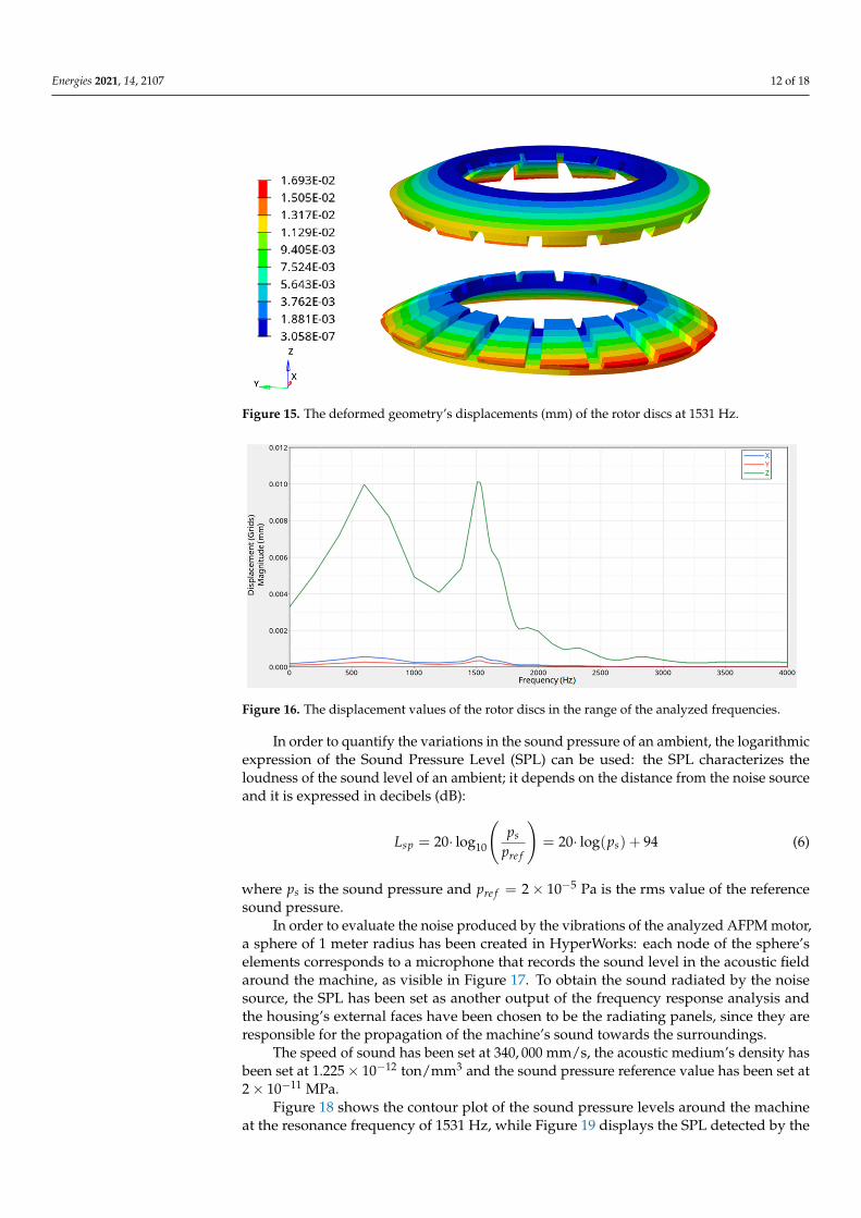
Figure 15 shows the rotor deformed geometry’s displacements of the AFPM machine atthe resonance frequency of 1531 Hz, while Figure 16 displays the rotor discs’ displacements,whose peak values are equal to 0.01 mm for the z-axis direction at both the mechanicalsystem’s natural frequencies of 600 Hz and 1531 Hz; the values of the displacements areacceptable and do not interfere with the operating conditions of the machine, since it is clearthat the rotor discs, and hence the permanent magnets (with a maximum displacement’svalue of 0.014 mm), do not touch the inner stator. Regarding the deformed geometry’svelocities of the rotor’s disc, the maximum value at 1531 Hz is equal to 100 mm/s.
With regard to the noise produced by an electrical machine, it can be stated that morevibrations produce more sound. There are different parameters that can affect a machine’ssound radiation: its dimensions, its material properties, the excitations and the conditionsof the surroundings. There are two types of noise: the structure-borne one, which is causedby the vibrations of solid objects, and the air-borne noise, caused by the movement of largeair volumes or by the use of high-pressure.
Energies 2021, 14, 2107 12 of 18
Figure 15. The deformed geometry’s displacements (mm) of the rotor discs at 1531 Hz.
Figure 16. The displacement values of the rotor discs in the range of the analyzed frequencies.
In order to quantify the variations in the sound pressure of an ambient, the logarithmicexpression of the Sound Pressure Level (SPL) can be used: the SPL characterizes theloudness of the sound level of an ambient; it depends on the distance from the noise sourceand it is expressed in decibels (dB):
Lsp = 20· log10
(ps
pre f
)= 20· log(ps) + 94 (6)
where ps is the sound pressure and pre f = 2× 10⁻⁵ Pa is the rms value of the referencesound pressure.
In order to evaluate the noise produced by the vibrations of the analyzed AFPM motor,a sphere of 1 meter radius has been created in HyperWorks: each node of the sphere’selements corresponds to a microphone that records the sound level in the acoustic fieldaround the machine, as visible in Figure 17. To obtain the sound radiated by the noisesource, the SPL has been set as another output of the frequency response analysis andthe housing’s external faces have been chosen to be the radiating panels, since they areresponsible for the propagation of the machine’s sound towards the surroundings.
The speed of sound has been set at 340, 000 mm/s, the acoustic medium’s density hasbeen set at 1.225× 10⁻¹² ton/mm3 and the sound pressure reference value has been set at2× 10−11 MPa.
Figure 18 shows the contour plot of the sound pressure levels around the machineat the resonance frequency of 1531 Hz, while Figure 19 displays the SPL detected by the

Energies 2021, 14, 2107 13 of 18
sphere’s microphones in the red zone: the maximum sound pressure level obtained by thosemicrophones and, hence, radiated by the AFPM machine during its nominal operatingconditions reaches the value of 65 dB, which is acceptable for this type of application.
Figure 17. The sphere of microphones used to detect the AFPM motor’s radiated sound.
Figure 18. The sound pressure level in (dB) on the chromatic microphone sphere.
Figure 19. The sound pressure level detected by the red zone’s microphones.

Energies 2021, 14, 2107 14 of 18
4.3. Thermal Analysis
Thermal analyses are of great relevance, especially concerning PM machines becauseof the permanent magnet sensitivity to high operating temperatures, which could lead tothe PM demagnetization. In order to avoid that and to ensure the AFPM motor reliability,a thermal analysis has been carried out with the Altair Finite Element Method (FEM)software used for Computational Fluid Dynamics (CFD) simulations: in this workspace,the conductive heat transfers have been modeled and the convective ones have beenimposed; however, the fluid dynamics has been neglected in this context. Considering thechosen cooling system (forced-air) and the base speed working point, it has been possibleto establish whether the insulating materials, the bearings and the permanent magnetscould be damaged by high temperatures, which could have also caused higher losses and,therefore, a lower efficiency of the electric machine.
The machine losses have been considered as heat sources: the main ones are dueto the Joule losses, to the stator and rotor iron losses and to the PM losses, while theother contributions are lower and, therefore, they have not been considered in this 3D FEsimulation [19]. The material thermal properties have been assigned to each machine’scomponent, as it can be seen in Table 6.
Table 6. Thermal properties of the chosen materials.
Specific Heat Thermal Conductivity Density
Fe-Co Alloy 430 J/(kgK) 32 W/(mK) 8600 kg/m3
Copper 377 J/(kgK) 385 W/(mK) 8960 kg/m3
NdFeB 450 J/(kgK) 7 W/(mK) 7400 kg/m3
Steel 434 J/(kgK) 52 W/(mK) 7850 kg/m3
After that each material has been assigned to the correspondent components, it hasbeen possible to define the internal heat sources starting from the machine losses mentionedabove: their values are shown in Table 7.
Table 7. Internal heat sources of the machine.
Machine loss Unit Value
Joule losses W/m3 1,785,000PM losses W/m3 200,630Iron losses W/m3 274,435
Considering a forced-air cooling system, which has been chosen to provide a bettercooling of the machine than the one provided by a natural-air cooling system, the convectiveheat transfer coefficients have been empirically estimated to determine the boundaryconditions for the CFD simulation. Some assumptions must be made: one side of theAFPM motor housing is clamped to the chassis of the vehicle; the rotor rings are keyed tothe inner side of the wheel’s rim (with a 24 cm radius); the ambient temperature is equal to20 C. Assuming that the motor base speed corresponds to 21 m/s of the electric vehicle’swheels and that some housing’s areas are directly hit by the air while others are less or byno means lapped by it, the average convective heat transfer coefficient used for the externalhousing’s surfaces (except for the one clamped to the chassis) can be seen in Table 8. Theother coefficients have been estimated considering that inside the machine’s housing thereis an improvement in the quality of the thermal exchange, which is mainly due to theturbulent motion of the two rotor discs and that depends almost linearly on the rotatingspeed and on the average diameter of the discs. Considering the faces of the permanentmagnets and of the stator teeth that face the air gap, they do not benefit from a great aircirculation because of the little space defined by the motor air gap itself; therefore, theirconvective heat transfer coefficient is quite low.
Energies 2021, 14, 2107 15 of 18
Table 8. Heat transfer coefficients of the machine’s surfaces.
Component Unit Value
External housing W/(m2K) 42.3Internal housing W/(m2K) 20
External shaft W/(m2K) 15Internal shaft W/(m2K) 25
Stator core W/(m2K) 21Windings W/(m2K) 21
Rotor core + PMs W/(m2K) 40Air gap surfaces W/(m2K) 28.8
Once the mesh has been created and considering the conductive and convective heattransfers between the machine’s components, the thermal analysis has been carried outand the temperature distributions shown in the following figures have been obtained.
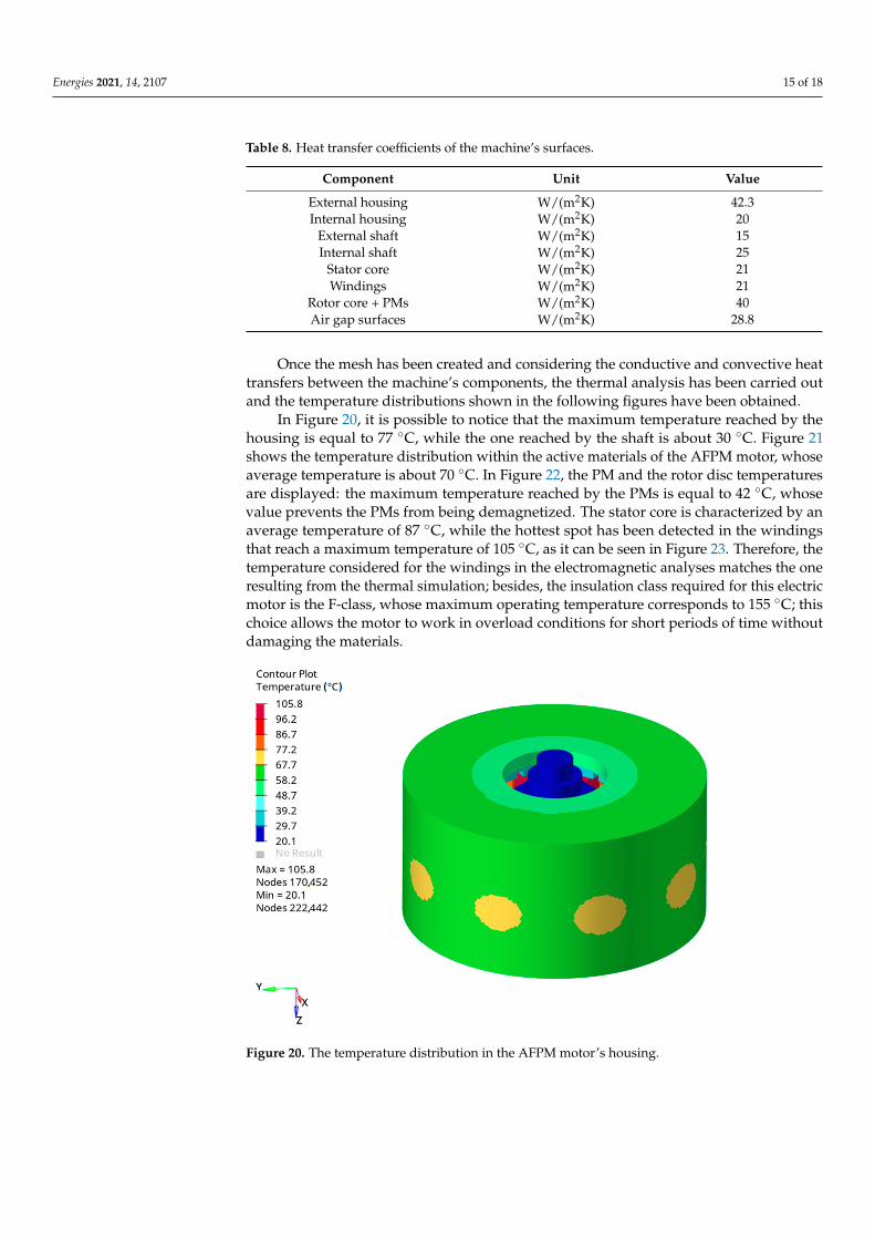
In Figure 20, it is possible to notice that the maximum temperature reached by thehousing is equal to 77 C, while the one reached by the shaft is about 30 C. Figure 21shows the temperature distribution within the active materials of the AFPM motor, whoseaverage temperature is about 70 C. In Figure 22, the PM and the rotor disc temperaturesare displayed: the maximum temperature reached by the PMs is equal to 42 C, whosevalue prevents the PMs from being demagnetized. The stator core is characterized by anaverage temperature of 87 C, while the hottest spot has been detected in the windingsthat reach a maximum temperature of 105 C, as it can be seen in Figure 23. Therefore, thetemperature considered for the windings in the electromagnetic analyses matches the oneresulting from the thermal simulation; besides, the insulation class required for this electricmotor is the F-class, whose maximum operating temperature corresponds to 155 C; thischoice allows the motor to work in overload conditions for short periods of time withoutdamaging the materials.
Figure 20. The temperature distribution in the AFPM motor’s housing.

Energies 2021, 14, 2107 16 of 18
Figure 21. The temperature distribution in the active materials of the AFPM motor.
Figure 22. The temperature distribution in the rotor discs with PMs.
Figure 23. An enlargement of the temperature distribution in the stator windings.

Energies 2021, 14, 2107 17 of 18
5. Conclusions
The direct-drive electric vehicle could be the future trend because it does not requiretransmission components and it allows to reduce the volume and the weight of the wholepowertrain system while improving its efficiency. For this specific application, the axialflux permanent magnet motor represents a valid alternative to the traditional radial fluxmotor due to the possibility of placing it inside the vehicle’s wheels so that the reducer anddifferential gears can be suppressed. Due to the integration of the transmission gear withthe motor, the heat dissipation, lubrication, protection, and torque output capacity of thein-wheel motor system can be significantly improved.
A small pure electric vehicle with gearless in-wheel motors has been considered as acase study; the basic drive architecture includes four axial flux motors installed directlyinside the vehicle’s wheels.
In this paper, advanced and integrated electromagnetic, vibroacoustic and thermalanalyses have been proposed in order to investigate, in a detailed and exhaustive way, theaxial flux motor behavior.
In particular, the modal analysis and the frequency response analysis on a modalbasis of the electrical machine’s mechanical system (complete with housing and shaft)have been carried out. Moreover, the deformed geometries at the resonance frequenciesof all the motor components have been evaluated in terms of displacement, velocity andacceleration together with the noise produced by the vibrations of the analyzed AFPMmotor. For the purpose of this paper, only the main results have been displayed: the rotordiscs’ displacements due to the resonance phenomenon do not interfere with the nominaloperating conditions of the analyzed axial flux PM machine.
In conclusion, considering that all the aspects evaluated for the application of thedesigned electric motor in the automotive field, together with the initial requirements(in terms of torque and power), have been satisfied (see Table 3), it can be stated thatthe analyzed AFPM motor is suitable for traction applications, showing indeed goodpower and torque densities. Moreover, the thermal analysis’ results reveal that the choseninsulation class is appropriate for the studied machine. Finally, it is possible to notice, fromthe vibroacoustic analyses, that the vibrations generated at base speed by the electric motorare acceptable; in fact, they produce an emitted sound lower than 65 dB, making the motoritself suitable, in terms of comfort and environmental impact, to be placed in an electricvehicle. After this multiphysics analysis, it is therefore possible to move on to the next step:a dynamic analysis of the electric vehicle that includes four in-wheel AFPM motors.
Author Contributions: Conceptualization, M.T. and M.V.; methodology, A.C. and M.V.; software,C.D.L., F.F. and M.O.; writing—original draft preparation, M.V.; writing—review and editing, A.C.and C.D.L.; visualization, A.C. and C.D.L.; supervision, M.T. and M.V. All authors have read andagreed to the published version of the manuscript.
Funding: This research received no external funding.
Conflicts of Interest: The authors declare no conflict of interest.
References1. Zhao, J.; Han, Q.; Dai, Y.; Hua, M. Study on the Electromagnetic Design and Analysis of Axial Flux Permanent Magnet
Synchronous Motors for Electric Vehicles. Energies 2019, 12, 3451. [CrossRef]2. Gao, P.; Gu, Y.; Wang, X. The Design of a Permanent Magnet In-Wheel Motor with Dual-Stator and Dual-Field-Excitation Used in
Electric Vehicles. Energies 2018, 11, 424. [CrossRef]3. Rahman, K.M.; Patel, N.J.; Ward, T.; Nagashima, J.; Caricchi, F.; Crescimbini, F. Application of Direct-Drive Wheel Motor for Fuel
Cell Electric and Hybrid Electric Vehicle Propulsion System. IEEE Trans. Ind. Appl. 2006, 42, 1185–1192. [CrossRef]4. Deng, Q.-L.; Xiao, F.; Huang, W.-T. Design of New-type Axial Flux Permanent Magnet in-Wheel Machine. In Proceedings of the
2010 International Conference on Electrical and Control Engineering IEEE, Wuhan, China, 25–27 June 2010; pp. 5831–5834.5. Xiao, F.; Deng, Q.-L.; Liu, J.-C. Design of direct-drive axial flux permanent magnet in-wheel machine for electric vehicle. In
Proceedings of the 2011 International Conference on Electrical Machines and Systems, Beijing, China, 20–23 August 2011; pp. 1–4.[CrossRef]
Energies 2021, 14, 2107 18 of 18
6. Takorabet, N.; Martin, J.P.; Meibody-Tabar, F.; Sharif, F.; Fontaine, P. Design and optimization of a permanent magnet axial fluxwheel motors for electric vehicle. In Proceedings of the 2012 XXth International Conference on Electrical Machines, Marseille,France, 2–5 September 2012; pp. 2635–2640. [CrossRef]
7. Moreels, D. Axial flux motor topology: Will it dominate the future? In Proceedings of the International Motor Summit 2020,Zurich, Switzerland, 18–19 November 2020.
8. Cetin, E.; Daldaban, F. Analyzing the Profile Effects of the Various Magnet Shapes in Axial Flux PM Motors by Means of 3D-FEA.Electronics 2018, 7, 13. [CrossRef]
9. Hajnrych, S.J.; Jakubowski, R.; Szczypior, J. Yokeless Axial Flux Surface-Mounted Permanent Magnets Machine Rotor ParametersInfluence on Torque and Back-Emf. Energies 2020, 13, 3418. [CrossRef]
10. Mlot, A.; González, J. Performance Assessment of Axial-Flux Permanent Magnet Motors from a Manual Manufacturing Process.Energies 2020, 13, 2122. [CrossRef]
11. Deng, W.; Zuo, S. Analytical Modeling of the Electromagnetic Vibration and Noise for an External-Rotor Axial-Flux in-WheelMotor. IEEE Trans. Ind. Electron. 2018, 65, 1991–2000. [CrossRef]
12. Gieras, J.F.; Wang, R.-J.; Kamper, M.J. Axial Flux Permanent Magnet Brushless Machines, 2nd ed.; Springer Netherlands: Dordrecht,The Netherlands, 2008.
13. Capponi, F.G.; De Donato, G.; Caricchi, F.A. Recent Advances in Axial-Flux Permanent-Magnet Machine Technology. IEEE Trans.Ind. Appl. 2012, 48, 2190–2205. [CrossRef]
14. Marignetti, F.; Colli, V.D.; Di Stefano, R.; Cavagnino, A. Design Issues of a Fractional-Slot Windings Axial Flux PM Machine withSoft Magnetic Compound Stator. In Proceedings of the IECON 2007—33rd Annual Conference of the IEEE Industrial ElectronicsSociety, Taipei, Taiwan, 5–8 November 2007; pp. 187–192. [CrossRef]
15. Chai, F.; Bi, Y.; Chen, L. A Comparison between Axial and Radial Flux Permanent Magnet In-Wheel Motors for Electric Vehicle.In Proceedings of the 2020 International Conference on Electrical Machines (ICEM), Online. 23–26 August 2020; Volume 1,pp. 1685–1690.
16. Torregrossa, D.; Peyraut, F.; Cirrincione, M.; Espanet, C.; Cassat, A.; Miraoui, A. A New Passive Methodology for Reducing theNoise in Electrical Machines: Impact of Some Parameters on the Modal Analysis. IEEE Trans. Ind. Appl. 2010, 46, 1899–1907.[CrossRef]
17. Deng, W.; Zuo, S.; Lin, F.; Wu, S. Influence of pole and slot combinations on vibration and noise in external rotor axial fluxin-wheel motors. IET Electr. Power Appl. 2017, 11, 586–594. [CrossRef]
18. Gieras, J.F.; Wang, C.; Lai, J.C. Noise of Polyphase Electric Motors; CRC/Taylor & Francis: Boca Raton, FL, USA, 2018.19. Li, D.; Wen, Y.; Li, W.; Feng, B.; Cao, J. Three-Dimensional Temperature Field Calculation and Analysis of an Axial-Radial
Flux-Type Permanent Magnet Synchronous Motor. Energies 2018, 11, 1208. [CrossRef]
![Design of Axial-Flux Motor for Traction Applicationradial-flux motors, the axial-flux ones can be modulated which leads to the increase of their torque generation capabilities [1,2,4]](https://img.pdfslide.net/doc/110x75/5e7ecdb1efdfb0767a23aa9b/design-of-axial-flux-motor-for-traction-application-radial-flux-motors-the-axial-flux.jpg)