Embed Size (px)
Citation preview
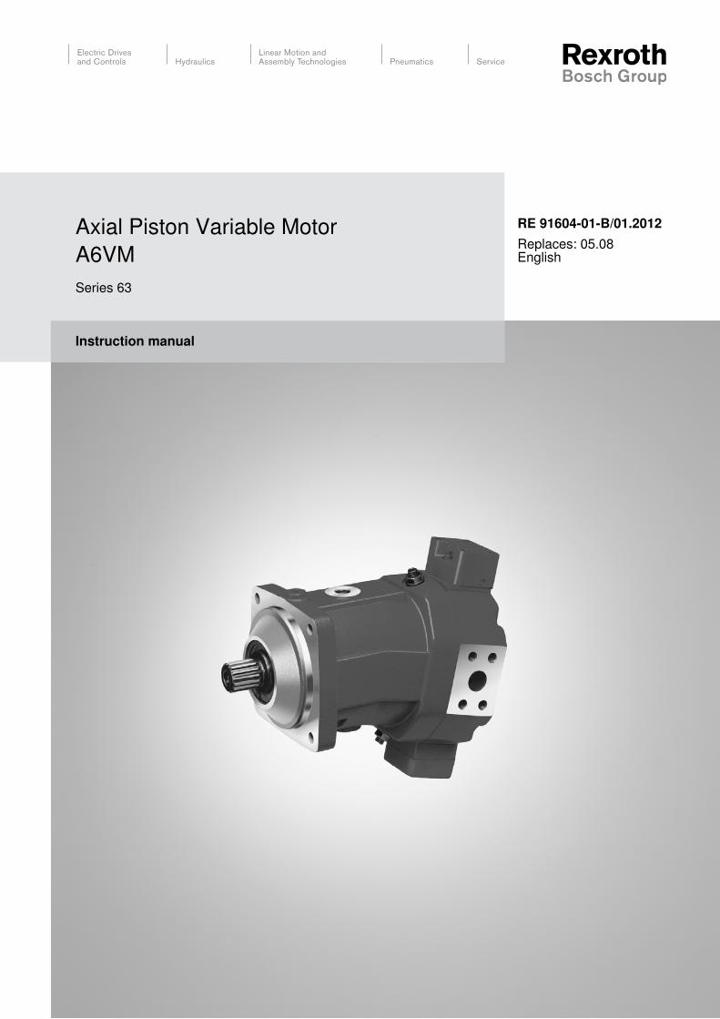
Instruction manual
RE 91604-01-B/01.2012Replaces: 05.08English
Axial Piston Variable MotorA6VMSeries 63
The data specified above serve to describe the product. Should information be provided on use, these are only examples of applications and suggestions.Information from the catalog are not assured properties. The information given does not release the user from the obligation of own judgment and verification. Our products are subject to a natural wear and aging process.
© This document, as well as the data, specifications and other information set forth in it, are the exclusive property of Bosch Rexroth AG.It may not be reproduced or given to third parties without its consent.
The cover shows an example application. The product delivered may differ from the image on the cover.
The original instruction manual were created in the German language.
RE 91604-01-B/01.2012 | A6VM Series 63 Bosch Rexroth AG 3/56
Contents1 About this manual .....................................................................................51.1 Validity of the documentation ......................................................................51.2 Required and supplementary documentation .............................................51.3 Display of information ..................................................................................61.3.1 Safety instructions .......................................................................................61.3.2 Symbols ......................................................................................................61.3.3 Designations ...............................................................................................71.3.4 Abbreviations ..............................................................................................72 Safety instructions ....................................................................................82.1 About this chapter .......................................................................................82.2 Intended use ...............................................................................................82.3 Improper use ...............................................................................................82.4 Personnel qualifications ..............................................................................92.5 General safety instructions ..........................................................................92.6 Product-specific safety instructions ...........................................................112.7 Personal protective equipment ..................................................................123 General instructions on damage to equipment and the product .......134 Delivery contents ....................................................................................155 Product description ................................................................................165.1 Performance description ...........................................................................165.2 Product description ...................................................................................165.2.1 Assembly of the axial piston unit ...............................................................165.2.2 Functional description ...............................................................................175.3 Product identification .................................................................................186 Transport and storage ............................................................................196.1 Transporting the axial piston unit ..............................................................196.1.1 Transporting by hand ................................................................................196.1.2 Transporting with lifting device ..................................................................196.2 Storing the axial piston unit .......................................................................217 Installation ...............................................................................................237.1 Unpacking .................................................................................................237.2 Installation conditions ................................................................................237.3 Installation position ....................................................................................257.3.1 Below-reservoir installation (standard) ......................................................257.3.2 Above-reservoir installation .......................................................................267.4 Installing the axial piston unit ....................................................................277.4.1 Preparation ................................................................................................277.4.2 Dimensions ...............................................................................................277.4.3 General instructions ..................................................................................277.4.4 Installation with coupling ...........................................................................287.4.5 Installation on a gearbox ...........................................................................297.4.6 Installation with cardan shaft .....................................................................297.4.7 Completing installation ..............................................................................297.4.8 Hydraulically connecting the axial piston unit ............................................307.4.9 Electrically connecting the axial piston unit ...............................................377.5 Performing flushing cycle ..........................................................................388 Commissioning .......................................................................................398.1 First commissioning ..................................................................................398.1.1 Filling the axial piston unit .........................................................................398.1.2 Testing the hydraulic fluid supply ..............................................................408.1.3 Performing functional test .........................................................................418.2 Running-in phase ......................................................................................418.3 Recommissioning after standstill ...............................................................429 Operation .................................................................................................43
Contents
4/56 Bosch Rexroth AG A6VM Series 63 | RE 91604-01-B/01.2012
10 Maintenance and repair ..........................................................................4410.1 Cleaning and care .....................................................................................4410.2 Inspection ..................................................................................................4510.3 Maintenance ..............................................................................................4510.4 Repair ........................................................................................................4510.5 Spare parts ................................................................................................4611 Removal and replacement ......................................................................4711.1 Required tools ...........................................................................................4711.2 Preparing for removal ................................................................................4711.3 Removing the axial piston unit ..................................................................4711.4 Preparing the components for storage or further use ...............................4712 Disposal ...................................................................................................4813 Extension and conversion .....................................................................4814 Troubleshooting ......................................................................................4914.1 How to proceed for troubleshooting ..........................................................4914.2 Malfunction table .......................................................................................5015 Technical data .........................................................................................5116 Appendix ..................................................................................................5116.1 Address directory ......................................................................................5117 Alphabetical index ..................................................................................52
Contents
RE 91604-01-B/01.2012 | A6VM Series 63 Bosch Rexroth AG 5/56
About this manual
About this manual1
Validity of the documentation1.1 This documentation applies to the following products:
Axial piston variable motor A6VM Series 63 •
This documentation is intended for machine/system manufacturers, fitters and service technicians.This documentation contains important information on the safe and appropriate installation, transport, commissioning, operation, maintenance, removal and simple troubleshooting of the axial piston unit.
Read this documentation completely and in particular chapter 2 "Safety finstructions" and chapter 3 "General instructions on damage to equipment and the product", before working with the axial piston unit.
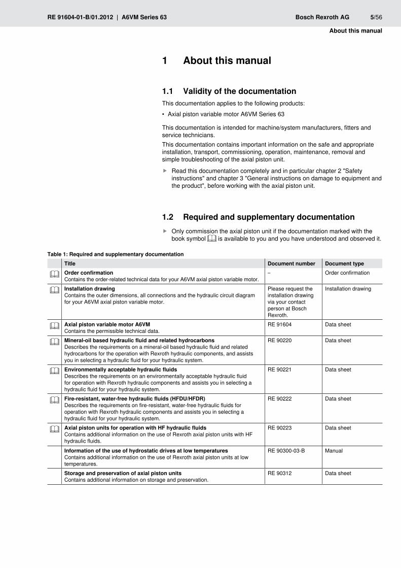
1.2 Required and supplementary documentationOnly commission the axial piston unit if the documentation marked with the fbook symbol is available to you and you have understood and observed it.
Required and supplementary documentationTable 1: Title Document number Document typeOrder confirmationContains the order-related technical data for your A6VM axial piston variable motor.
– Order confirmation
Installation drawingContains the outer dimensions, all connections and the hydraulic circuit diagram for your A6VM axial piston variable motor.
Please request the installation drawing via your contact person at Bosch Rexroth.
Installation drawing
Axial piston variable motor A6VMContains the permissible technical data.
RE 91604 Data sheet
Mineral-oil based hydraulic fluid and related hydrocarbonsDescribes the requirements on a mineral-oil based hydraulic fluid and related hydrocarbons for the operation with Rexroth hydraulic components, and assists you in selecting a hydraulic fluid for your hydraulic system.
RE 90220 Data sheet
Environmentally acceptable hydraulic fluidsDescribes the requirements on an environmentally acceptable hydraulic fluid for operation with Rexroth hydraulic components and assists you in selecting a hydraulic fluid for your hydraulic system.
RE 90221 Data sheet
Fire-resistant, water-free hydraulic fluids (HFDU/HFDR)Describes the requirements on fire-resistant, water-free hydraulic fluids for operation with Rexroth hydraulic components and assists you in selecting a hydraulic fluid for your hydraulic system.
RE 90222 Data sheet
Axial piston units for operation with HF hydraulic fluidsContains additional information on the use of Rexroth axial piston units with HF hydraulic fluids.
RE 90223 Data sheet
Information of the use of hydrostatic drives at low temperaturesContains additional information on the use of Rexroth axial piston units at low temperatures.
RE 90300-03-B Manual
Storage and preservation of axial piston unitsContains additional information on storage and preservation.
RE 90312 Data sheet
6/56 Bosch Rexroth AG A6VM Series 63 | RE 91604-01-B/01.2012
About this manual
Display of information1.3 Standardized safety instructions, symbols, terms and abbreviations are used so that you can use this documentation to work quickly and safely with your axial piston unit. To give you a better understanding they are explained in the sections below.
Safety instructions1.3.1 Safety instructions are contained in this documentation in chapter 2.6 "Product-specific safety instructions" and chapter 3 "General instructions on damage to equipment and the product" as well as before a sequence or instruction whenever there is a risk of injury to persons or damage to equipment. The measures described to avoid these hazards must be observed.Safety instructions are set out as follows:
SIGnAl wORD!Type and source of dangerConsequences in case of noncompliance
Measure for danger prevention f<List> f
Safety sign: • draws attention to the dangerSignal word: • identifies the degree of the dangerType and source of danger: • identifies the type and source of the dangerConsequences: • describes what occurs if the safety instructions are not complied withPrecautions: • states how the danger can be avoided
Danger classes in accordance with AnSI Z535.6-2006Table 2:
Safety sign, signal word Meaning
DAnGER Identifies a dangerous situation that will result in death or serious injuries if it is not avoided.
wARnInG Identifies a dangerous situation that may result in death or serious injuries if it is not avoided.
CAUTIOn Identifies a dangerous situation that may result in minor to moderate injuries if it is not avoided.
NOTE Damage to equipment: the product or the environment may be damaged.
1.3.2 SymbolsThe following symbols mark notes that are not safety-relevant but which increase the understanding of the documentation.
Meaning of the symbolsTable 3: Symbol Meaning
If this information is disregarded, the product can not be used and/or operated to the optimum extent.
f Single, independent step
1.
2.
3.
Numbered instruction:The numbers specify that the steps are completed one after the other.
RE 91604-01-B/01.2012 | A6VM Series 63 Bosch Rexroth AG 7/56
About this manual
1.3.3 DesignationsThis documentation uses the following designations:
DesignationsTable 4: Designation MeaningA6VM Axial piston variable motor, open and closed circuits
Screw plug Metal screw, pressure-resistant
Protective plug Made out of plastic, not pressure-resistant, only for transportation
As umbrella term for "axial piston variable motor A6VM", the designation "axial piston unit" will be used in the following.
1.3.4 AbbreviationsThis documentation uses the following abbreviations:
AbbreviationsTable 5: Abbreviation MeaningDA Hydraulic control, speed relatedDIN Deutsche Industrie norm (German Institute for Standardization)EP Electrical control, with proportional solenoidEZ Electric two-point control, with switching solenoidHA Automatic control, high-pressure relatedHD Hydraulic control, pilot-pressure relatedHZ Hydraulic two-point controlISO International Organization for StandardizationRE Rexroth document in the English languageVDI 2230 Directive for the systematic calculation of high duty bolted
joints and joints with one cylindrical bolt from the VDI (Verein Deutscher Ingenieure – Association of German Engineers)
8/56 Bosch Rexroth AG A6VM Series 63 | RE 91604-01-B/01.2012
Safety instructions
2 Safety instructions
About this chapter2.1 The axial piston unit has been manufactured according to the generally accepted rules of current technology. There is, however, still a danger of personal injury or damage to equipment if this chapter and the safety instructions in this documentation are not complied with.
Read this documentation completely and thoroughly before working with the faxial piston unit.Keep this documentation in a location where it is accessible to all users at all ftimes.Always include the required documentation when you pass the axial piston funit on to third parties.
2.2 Intended useAxial piston units are hydraulic components, meaning that in their application they are classified neither as complete nor as incomplete machines in the sense of the EU machine directive 2006/42/EC. A component is exclusively intended to form an incomplete or a complete machine together with other components. The component may only be commissioned after it has been installed in the machine/system for which it is intended and the safety of the entire system has been established in accordance with the machine directive.The product is intended for the following use:The axial piston unit is only approved for use as a hydraulic motor in hydrostatic drives.
Observe the technical data, application and operating conditions and fperformance limits as specified in data sheet RE 91604 and in the order confirmation. Information about approved hydraulic fluids can be found in data sheet RE 91604.
The axial piston unit is only intended for professional use and not for private use.Intended use includes having completely read and understood this documentation, especially chapter 2 "Safety instructions".
Improper use2.3 Any use other than that described as intended use shall be considered as improper and is therefore impermissible.Bosch Rexroth AG shall accept no liability whatsoever for damage resulting from improper use. The user shall bear all risks arising from improper use.Similarly, the following foreseeable faulty usages are also considered to be improper:
Using outside the operating parameters approved in the data sheet (unless •customer-specific approval has been granted)Use for non-approved fluids • , e.g. water or polyurethane componentsModification of factory settings by non-authorized persons •Use of add/on parts (e.g. mountable filter, control unit, valves) that are not •specified Rexroth componentsUsing the axial piston unit under water at a depth of more than 10 meters •without necessary additional measures, e.g. pressure equalization
RE 91604-01-B/01.2012 | A6VM Series 63 Bosch Rexroth AG 9/56
Safety instructions
Using the axial piston unit when the exterior pressure is greater than the interior •pressure (case pressure)Using the axial piston unit in explosive environments unless the •component or machine/system has been certified as compliant with the ATEX directive 94/9/ECUsing the axial piston unit in an aggressive atmosphere •Using the axial piston unit in aircraft or space craft •
2.4 Personnel qualificationsThe activities described in this documentation require basic mechanical, electrical and hydraulic knowledge, as well as knowledge of the associated technical terms. For transporting and handling the product, additional knowledge is necessary with regard to working with a lifting device and the corresponding attachment equipment. In order to ensure safe use, these activities may therefore only be carried out by appropriate qualified personnel or an instructed person under the direction and supervision of qualified personnel.Qualified personnel are those who can recognize possible hazards and institute the appropriate safety measures due to their professional training, knowledge, and experience, as well as their understanding of the relevant conditions pertaining to the work to be done. Qualified personnel must observe the rules relevant to the subject area and have the necessary hydraulic knowledge.Hydraulic knowledge means, for instance:
reading and fully understanding hydraulic plans, •fully understanding in particular the interrelationships regarding safety devices, •andhaving knowledge on the function and assembly of hydraulic components. •
Bosch Rexroth offers training support for special fields. You can find an overview of the training contents in the Internet at: http://www.boschrexroth.de/didactic.
2.5 General safety instructionsObserve the applicable accident prevention and environmental protection •regulations.Observe the safety regulations and provisions of the country in which the •product is used/operated.Use Rexroth products only when they are in good technical order and condition. •Observe all notes on the product. •Persons who install, operate, remove or maintain Rexroth products must not •consume any alcohol, drugs or pharmaceuticals that may affect their ability to respond.Only use Rexroth original accessories and spare parts to ensure there is no risk •to persons from unsuitable spare parts.Conform to the technical data and ambient conditions specified in the product •documentation.If unsuitable products are installed or used in applications that are of relevance •to safety, unexpected operating conditions may occur in the application which could result in injury to persons or property damage. For this reason, only use the product in a safety-relevant application if this use is expressly specified and permitted in the product documentation, for example in ex-protection applications or in safety-related parts of a control system (functional safety).

10/56 Bosch Rexroth AG A6VM Series 63 | RE 91604-01-B/01.2012
Safety instructions
You may only commission the product if it has been determined that the end •product (e.g. machinery or a system) into which the Rexroth products are installed complies with the country-specific provisions, safety regulations and standards of the application.
RE 91604-01-B/01.2012 | A6VM Series 63 Bosch Rexroth AG 11/56
Safety instructions
2.6 Product-specific safety instructionsThe following safety instructions apply for chapters 6 to 14.
wARnInGDanger from suspended loads!Danger to life or risk of injury, damage to equipment!Improper transportation may cause the axial piston unit to fall down lead to injuries e.g. crushing or broken bones or damage to the product.
Make certain that the forklift truck or lifting device has adequate lifting fcapacity.Never stand under or put you hands under suspended loads. fEnsure your position is stable during transportation. fUse your personal protective equipment (e.g. safety glasses, safety gloves, fsuitable working clothes, safety shoes).Use suitable lifting devices for transportation. fObserve the prescribed position of the lifting strap. fObserve the national laws and regulations on work and health protection fand transportation.
Pressurized machine/system!Danger to life or risk of injury, serious injuries when working on machines/systems not shutdown! Damage to equipment!
Protect the complete system against being energized. fMake sure that the machine/system is depressurized. Please follow the fmachine/system manufacturer’s instructions.Do not disconnect any line connections, ports and components when the fmachine/system is pressurized.Switch off all power-transmitting components and connections (electric, fpneumatic, hydraulic) in accordance with the manufacturer's instruction and secure them against being switched back on.
Escaping oil mist!Danger of explosion, danger of fire, allergic reactions, environmental pollution!
Depressurize the machine/system and repair the leak. fOnly perform welding work then the machine/system is depressurized. fKeep open flames and ignition sources away from the axial piston unit. fIf axial piston units are to be situated in the vicinity of ignition sources or fpowerful thermal radiators, a shield must be erected to ensure that any escaped hydraulic fluid can not ignite, and to protect hose lines from premature aging.
Electrical voltage!Risk of injury due to electric shock or damage to equipment!
Always set up the relevant part of the machine/system so that it is free of felectrical voltage before you install the product or when connecting and disconnecting plugs. Protect the machine/system against being energized.
12/56 Bosch Rexroth AG A6VM Series 63 | RE 91604-01-B/01.2012
Safety instructions
CAUTIOnHigh noise development in operation!Danger of hearing damage, deafness!The noise emission of axial piston units depends on speed, operating pressure and installation conditions. The sound pressure level may rise above 70 dBA during normal operating conditions.
Always wear hearing protection when in the vicinity of the operating axial fpiston unit.
Hot surfaces on the axial piston unit!Risk of burns!
Allow the axial piston unit to cool down sufficiently before touching it. fWear heat-resistant protective clothing, e.g. gloves. f
Improper routing of cables and lines!Tripping hazard and damage to equipment!
Lay cables and lines so that they can not be damaged and nobody can trip fover them.
Contact with hydraulic fluid!Hazard to health/health impairment e.g. eye injuries, skin damage, toxication during inhalation!
Avoid contact with hydraulic fluids. fWhen working with hydraulic fluids, strictly observe the safety instructions fprovided by the lubricant manufacturer.Use your personal protective equipment (e.g. safety glasses, safety gloves, fsuitable working clothes, safety shoes).If hydraulic fluid should, nevertheless, come into contact with your eyes or fbloodstream or is swallowed, consult a doctor immediately.
Escaping hydraulic fluid due to machine/system leakage!Risk of burns and risk of injury due to escaping oil jet!
Depressurize the machine/system and repair the leak. fNever attempt to block or seal the leak or oil jet with a cloth. f
Personal protective equipment2.7 The personal protective equipment is the responsibility of the user of the axial piston unit. Observe the safety regulations and provisions of your country.All components of the personal protective equipment must be intact.
RE 91604-01-B/01.2012 | A6VM Series 63 Bosch Rexroth AG 13/56
General instructions on damage to equipment and the product
General instructions on 3 damage to equipment and the product
The following notes apply for chapters 6 to 14.
NOTEDanger from improper handling!Product can be damaged!
Do not expose the product to an impermissible mechanical load. fNever use the product as a handle or step. fDo not place/lay any objects on the product. fDo not strike the drive shaft of the axial piston unit. fDo not set/place the axial piston unit on the drive shaft. fDo not strike sensitive fittings (e.g. sensors or valves). fDo not strike sealing surfaces (e.g. service line ports). fLeave the protective covers on the axial piston unit until shortly before the flines are connected.
Damage to equipment due to improper lubrication!Product can be damaged or destroyed!
Never operate the axial piston unit with insufficient hydraulic fluid. Make sure fin particular that the rotary group has sufficient lubrication.When commissioning a machine/system, make sure that the case interior fand the service lines of the axial piston unit are filled with hydraulic fluid and remain filled during operation. Air intrusions in the forward drive shaft bearing are to be prevented, especially with the installation position "drive shaft upwards".With the installation position "drive shaft upwards" additional air bleeding is fto be provided via the flushing port U.Check the hydraulic fluid level in the case interior regularly; if necessary, frecommission. With above-reservoir installation, the case interior may drain via the reservoir line after longer standstill periods (air enters via the shaft seal) or via the service line (gap leakage). The bearings are thus insufficiently lubricated at switch on.
Mixing of hydraulic fluids!Product can be damaged!
Before installation, remove all fluids from the axial piston unit to prevent fmixing with the hydraulic fluid used in the machine/system.Any mixing of hydraulic fluids of different manufacturers or different types of fthe same manufacturer is not permissible in general.
14/56 Bosch Rexroth AG A6VM Series 63 | RE 91604-01-B/01.2012
General instructions on damage to equipment and the product
NOTEContamination of the hydraulic fluid!The cleanliness of the hydraulic fluid has a considerable impact on the cleanliness and service life of the hydraulic system. Premature wear and malfunctions!
Make sure that the working environment at the installation site is fully free fof dust and foreign substances in order to prevent contaminants, such as welding beads or metal cuttings, from getting into the hydraulic lines and causing product wear or malfunctions. The axial piston unit must be installed in a clean condition.Use only clean connections, hydraulic lines and attachments (e.g. measuring fequipment).No contaminants may enter the connections when they are plugged. fBefore commissioning, make sure that all hydraulic connections are tight fand that all the connection seals and plugs are installed correctly to ensure that they are leakproof and fluids and contaminants are prevented from penetrating the product.Use a suitable filter system to filter hydraulic fluid during filling to minimize fsolid impurities and water in the hydraulic system.
Improper cleaning!Product can be damaged!
Plug all openings with the appropriate protective equipment in order to fprevent detergents from entering the hydraulic system.Never use solvents or aggressive detergents. Use only water and, fif necessary, a mild detergent to clean the axial piston unit.Do not point the power washer at sensitive components, e.g. shaft seal, felectrical connections and components.Use lint-free cloths for cleaning. f
Environmental pollution due to incorrect disposal!Careless disposal of the axial piston unit, the hydraulic fluid and the packaging material could lead to pollution of the environment!
Dispose of the axial piston unit, hydraulic f fluid and packaging in accordance with the national regulations in your country.Dispose of the hydraulic fluid in accordance with the applicable safety data fsheet for the hydraulic fluid.
Escaping or spilling hydraulic fluid!Environmental pollution and contamination of the ground water!
When filling and draining the hydraulic fluid, f always place a drip tray under the axial piston unit.Use an oil binding agent if hydraulic fluid is spilled. fObserve the information in the safety data sheet for the hydraulic f fluid and the specifications provided by the system manufacturer.
The warranty applies only to the delivered configuration. •The entitlement under warranty is rendered void if the product is incorrectly •installed, commissioned or operated, as well as in the case of improper use and/or handling.
RE 91604-01-B/01.2012 | A6VM Series 63 Bosch Rexroth AG 15/56
Delivery contents
4 Delivery contents1
2
2
1
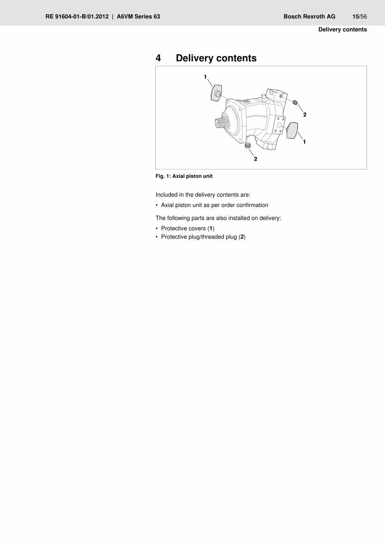
Axial piston unitFig. 1:
Included in the delivery contents are:
Axial piston unit as per order confirmation •
The following parts are also installed on delivery:
Protective covers ( • 1)Protective plug/threaded plug ( • 2)
16/56 Bosch Rexroth AG A6VM Series 63 | RE 91604-01-B/01.2012
Product description
Product description5
5.1 Performance descriptionThe axial piston variable motor converts hydrostatic flow into mechanical rotation. It is designed for mobile and stationary applications.Refer to data sheet RE 91604 and the order confirmation for the technical data, operating conditions and operating limits of the axial piston unit.
5.2 Product descriptionThe A6VM is a variable motor with axial piston rotary group of bent-axis design, for hydrostatic drives in open and closed circuits. For axial piston units with bent-axis design, the pistons (7) are arranged at an angle to the drive shaft (1). The pistons rest directly on the drive shaft where they generate torque depending on the pressure and swivel angle. The specific torque and displacement can be changed by adjusting the bent axis.In the open circuit, the hydraulic fluid flows from the reservoir to the hydraulic pump from where it is transported to the hydraulic motor. From the hydraulic motor, the hydraulic fluid flows directly back to the reservoir. The output direction of rotation of the hydraulic motor can be changed, e.g. by a directional valve.In the closed circuit, the hydraulic fluid flows from the hydraulic pump to the hydraulic motor and from there directly back to the hydraulic pump. The output direction of rotation of the hydraulic motor is changed, e.g. by reversing the flow direction in the hydraulic pump.
5.2.1 Assembly of the axial piston unit
1
2
3
45
6
7
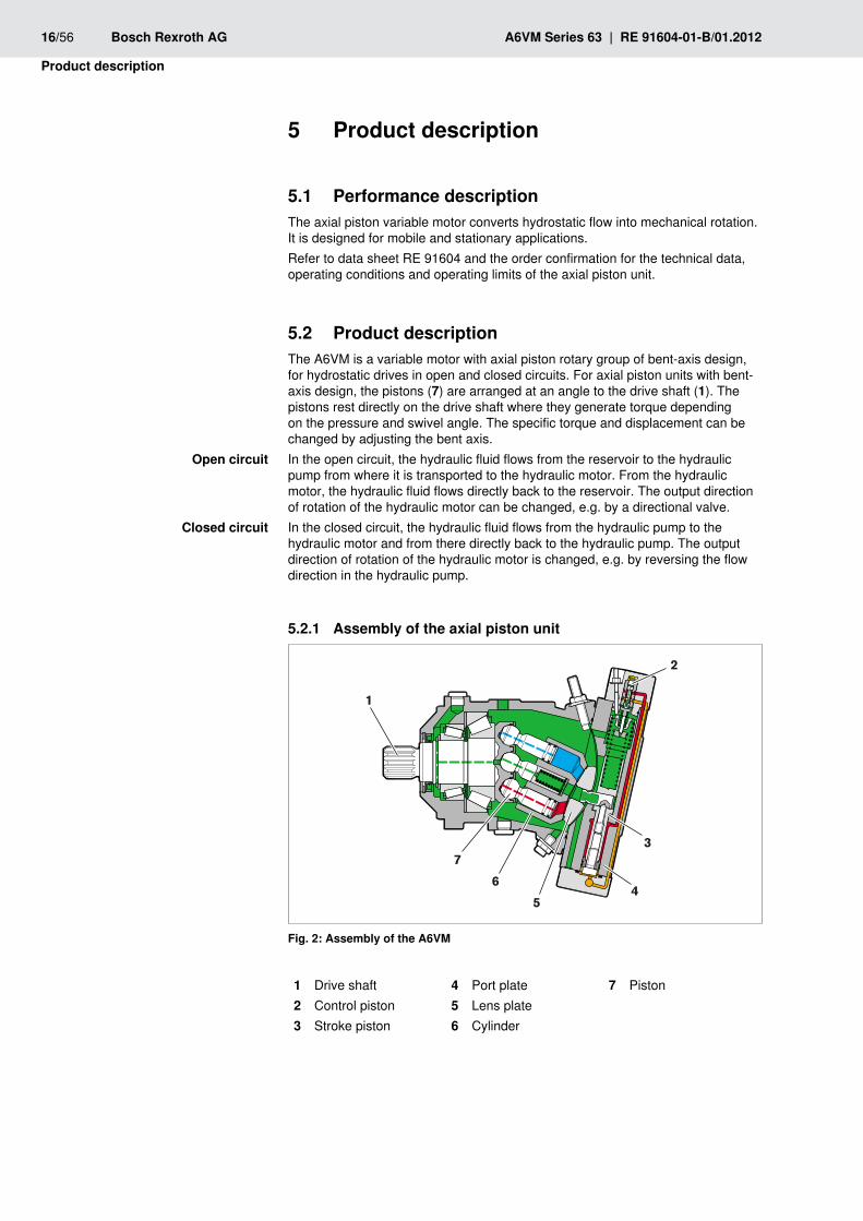
Assembly of the A6VMFig. 2:
1 Drive shaft2 Control piston3 Stroke piston
4 Port plate5 Lens plate6 Cylinder
7 Piston
Open circuit
Closed circuit
RE 91604-01-B/01.2012 | A6VM Series 63 Bosch Rexroth AG 17/56
Product description
Functional description5.2.2 A hydraulic motor converts hydrostatic energy into mechanical energy. Hydraulic fluid is directed via the port plate (4) and the lens plate (5) to the cylinder bores. The pistons (7) in the cylinder bores execute a stroke which is converted into rotation by the piston at the drive shaft flange. During this process, the pistons move the cylinder (6) and generate an output torque at the drive shaft. The output torque increases with the pressure difference between the high- and low-pressure sides and increasing displacement. The output speed is proportional to the inward flow and inversely proportional to the displacement of the hydraulic motor.The swivel angle of the bent axis rotary group can be steplessly varied. With two-point control (HZ, EZ), the swivel angle can be switched from maximum to minimum angle. Control of the swivel angle of the bent-axis rotary group changes the piston stroke and therefore the displacement. The swivel angle is controlled hydraulically by the stroke piston (3). The cylinder including piston and lens plate is swiveled thereby. The lens plate is mounted for easy motion in a guideway. Increasing the swivel angle results in an increase in the displacement and specific torque; decreasing the swivel angle results in a corresponding decrease of these values. The output speed is dependent on the input flow and the displacement of the hydraulic motor.
Various control devices are available depending on requirements. Information about this can be found in data sheet RE 91604.
The following warning concerns all axial piston units with the control part HD and EP:
CAUTIOnThe spring return feature in the control part is not a safety device!Internal contamination (contaminated hydraulic fluid, abrasion or residual contamination from system components) can cause the control part to stick in an undefined position. As a result, the volume flow of the axial piston unit will no longer respond correctly to the operator's commands.
Check whether the application on your machine requires additional safety fmeasures, in order to bring the driven actuator into a controlled and safe position (e. g. immediate stop).
Motor function
Control
18/56 Bosch Rexroth AG A6VM Series 63 | RE 91604-01-B/01.2012
Product description
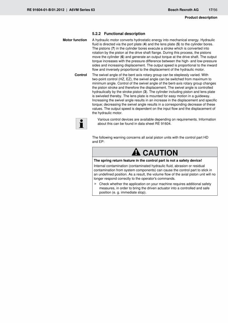
5.3 Product identificationThe axial piston unit can be identified from the name plate. The following example shows an A6VM name plate:
CNR:
MNR:SN:FD:
Rotation:
DE - 89275 Elchingen
Made in Germany
X1234567890Y
R90XXXXXXX SC: X12345678
Rexroth
2011W50m XXX kg
7202
Typ: A6VM160HA1T/63W-VAB027A
1
234
56
13
12
1110
9 Vg min = XXX,X cm3
78
A6VM name plate Fig. 3:
Manufacturer1 Sample category (optional)2 Internal plant designation3 Specified area for test stamp4 Direction of rotation (viewed on 5 drive shaft) – here: alternatingGround (optional)6
Barcode7 Minimum displacement8 Production date9 Serial number10 Material number of the 11 axial piston unitOrdering code12 Customer material number13
RE 91604-01-B/01.2012 | A6VM Series 63 Bosch Rexroth AG 19/56
Transport and storage
6 Transport and storageMake sure you conform to the required ambient conditions during ftransportation and storage, see chapter 6.2 "Storing the axial piston unit".
You can find unpacking notes in chapter 7.1 "Unpacking".
Transporting the axial piston unit6.1 The transportation options below exist depending on the weight and duration of the transport:
Transporting by hand •Transporting with • lifting device (ring screw or lifting strap)
Table 6: Dimensions and weightsSize 28 55 80 107 140 160 200 250 355 500 1000Ground kg 16 26 34 47 60 64 80 100 170 210 430
Width mm The dimensions vary with the pump type. The values applicable for your axial piston unit can be found in the installation drawing (request if necessary).
Height mmDepth mm
The weight specifications may vary depending on the pump type.
Transporting by hand6.1.1 Axial piston units with a weight of up to 15 kg can be transported manually for a short time if necessary.
CAUTIOn! Danger from heavy loads!There is a danger of health damage when carrying axial piston units.
Use suitable lifting, placement and relocation equipment. fUse your personal protective equipment (e.g. safety glasses, safety gloves, fsuitable working clothes, safety shoes).
Do not transport the axial piston unit at sensitive attachment parts f(e.g. sensors or valves).Carefully place the axial piston unit on the seating to prevent it from being fdamaged.
Transporting with lifting device6.1.2 For transporting, the axial piston unit can be connected to a lifting device via a ring screw or a lifting strap.The axial piston unit can be transported suspended from a ring screw screwed into the drive shaft as long as only outward (pulling) axial forces are applied.
For all female threads, use a threaded plug from the same system of units and fof the correct size.To do this, screw a ring screw completely into the thread on the drive shaft. fThe thread size is stated in the installation drawing.Make sure that the ring screw can bear the total weight of the axial piston unit fplus 20%.
Dimensions and weights
Transport with ring screw
20/56 Bosch Rexroth AG A6VM Series 63 | RE 91604-01-B/01.2012
Transport and storage
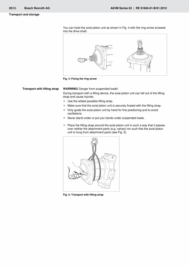
You can hoist the axial piston unit as shown in Fig. 4 with the ring screw screwed into the drive shaft.
Fixing the ring screwFig. 4:
wARnInG! Danger from suspended loads!During transport with a lifting device, the axial piston unit can fall out of the lifting strap and cause injuries.
Use the widest possible lifting strap. fMake sure that the axial piston unit is securely fixated with the lifting strap. fOnly guide the axial piston unit by hand for fine positioning and to avoid foscillations.Never stand under or put you hands under suspended loads. f
Place the lifting strap around the axial piston unit in such a way that it passes fover neither the attachment parts (e.g. valves) nor such that the axial piston unit is hung from attachment parts (see Fig. 5).
Transport with lifting strapFig. 5:
Transport with lifting strap
RE 91604-01-B/01.2012 | A6VM Series 63 Bosch Rexroth AG 21/56
Transport and storage
Storing the axial piston unit6.2 • The storage areas must be free from corrosive materials and gases.
To prevent damage to the seals, ozone-forming equipment (e.g. mercury-vapor •lamps, high voltage equipment, electric motors, sources of electrical sparks or electrical discharges) must not be operated in storage areas.The storage areas must be dry. •Ideal storage temperature: +5 °C to +20 °C. •Minimum storage temperature: -50 °C. •Maximum storage temperature: +60 °C. •Avoid high light irradiation (e.g. bright windows or direct fluorescent lighting). •Do not stack axial piston units and store them shock-proof. •Do not store the axial piston unit on sensitive attachment parts, e.g. speed •sensors.For other storage conditions, see Table 7. •
Check the axial piston unit monthly to ensure proper storage. f
The axial piston units are provided ex-works with corrosion protection packaging (corrosion protection film).The following table lists the maximum permissible storage times for an originally packed axial piston unit as per data sheet RE 90312.Table 7: Storage time with factory corrosion protection
Storage conditions Standard corrosion protection
long-term corrosion protection
Closed, dry room, uniform temperature between +5 °C and +20 °C. Undamaged and closed corrosion protection film.
Maximum 12 months Maximum 24 months
Entitlement to warranty will be rendered void if the requirements and storage conditions are not adhered to or after expiration of the maximum storage time (see Table 7).
Procedure after expiry of the maximum storage time:
Check the entire axial piston unit for damage and corrosion prior to 1. installation.
Check the axial piston unit for proper function and leaks during a test run.2.
If the storage time exceeds 24 months, the shaft seal ring must be replaced.3.
After expiry of the maximum storage time, we recommend that you have the axial piston unit inspected by your responsible Bosch Rexroth Service partner.
In the event of questions regarding repair and spare parts, contact your responsible Bosch Rexroth Service partner or the service department of the manufacturer's plant for the axial piston unit, see chapter 10.5 "Spare parts" for further information.
Requirement
After delivery
22/56 Bosch Rexroth AG A6VM Series 63 | RE 91604-01-B/01.2012
Transport and storage
If a removed axial piston unit is to be stored, it must be preserved against corrosion for the duration of storage.
The following instructions only refer to axial piston units which are operated with a mineral-oil based hydraulic fluid. Other hydraulic fluids require preservation methods that are specifically designed for them. In such a case, consult with Bosch Rexroth Service, see chapter 10.5 "Spare parts" for address.
Bosch Rexroth recommends the following procedure:
Clean the axial piston unit, see chapter 10.1 "Cleaning and care".1.
Empty the axial piston unit.2.
For storage time up to 12 months: Moisten the inside of the axial piston unit 3. with mineral oil and fill with approx. 100 ml mineral oil. For storage time up to 24 months: Fill the axial piston unit with corrosion protection medium VCI 329 (20 ml). Fill via the reservoir port T1 or T2, see chapter 7.4 "Installing the axial piston unit", Fig. 11 to 18.
Seal all ports 4. airproof.
Moisten the unpainted surfaces of the axial piston unit with mineral oil or a 5. suitable, easily removed corrosion protection agent, e.g. acid-free grease.
Package the axial piston unit airproof together with desiccant in corrosion 6. protection film.
Store the axial piston unit so that it is protected against jolts, see 7. "Requirement" in this chapter.
After removal
RE 91604-01-B/01.2012 | A6VM Series 63 Bosch Rexroth AG 23/56
Installation
7 InstallationPrior to installation, the following documents must be ready at hand:
Installation drawing for axial piston unit (can be obtained from your responsible •contact person at Bosch Rexroth)Hydraulic circuit diagram for the axial piston unit (in the installation drawing) •Hydraulic circuit diagram for the machine/system (available from the machine/ •system manufacturer)Order confirmation (contains the order-related technical data for your axial •piston unit)Data sheet of the axial piston unit (contains the permissible values of •technical data)
7.1 UnpackingThe axial piston unit is delivered in a corrosion protection film made of polyethylene material (PE).
CAUTIOn! Danger from parts falling out!If the packaging is not opened correctly, parts may fall out and damage the parts or even cause injuries!
Place the packaging on a flat and solid underground. fOnly open the packaging from the top. f
Remove the packaging from the axial piston unit. fCheck the axial piston unit for transport damage and completeness, fsee chapter 4 "Delivery contents".Dispose of the packaging according to the national regulations of your country. f
7.2 Installation conditionsThe installation location and position of the axial piston unit essentially determine the procedures during installation and commissioning (such as when filling and air bleeding the axial piston unit).
Fix the axial piston unit so that the expected forces and torques can be ftransferred without any danger. The machine/system manufacturer is responsible for dimensioning the fasteners.Observe the permissible radial forces on the drive shaft when transferring foutput drive with radial loading (belt drives). If necessary, the belt pulley must be separately mounted.Make sure that the axial piston unit is air bled and filled with hydraulic fluid fduring commissioning and operation. This is also to be observed following relatively long standstill periods as the axial piston unit may empty via the hydraulic lines.The case drain fluid in the case interior must be directed to the reservoir via fthe highest case drain port. Use the line size which is appropriate for the port.Avoid using a check valve in the reservoir line. fException: above-reservoir installation, shaft upward. A check valve in the reservoir line (cracking pressure 0.5 bar) can prevent draining via the reservoir line. Note the correct flow direction.To achieve favorable noise values, decouple all connecting lines from all fvibration-capable components (e.g. reservoir) using elastic elements.

24/56 Bosch Rexroth AG A6VM Series 63 | RE 91604-01-B/01.2012
Installation
Make sure that the reservoir and return lines lead into the reservoir below the fminimum fluid level in all operating conditions. You prevent foam formation by doing this.Make sure that the working environment at the installation site is fully free of fdust and foreign substances. The axial piston unit must be installed in a clean condition. Dirt contamination in the hydraulic fluid can seriously impair the function and service life of the axial piston unit.Use lint-free cloths for cleaning. fUse suitable mild detergents to remove lubricants and other difficult-to-remove fcontamination. Cleaning agents must not enter the hydraulic system.
RE 91604-01-B/01.2012 | A6VM Series 63 Bosch Rexroth AG 25/56
Installation
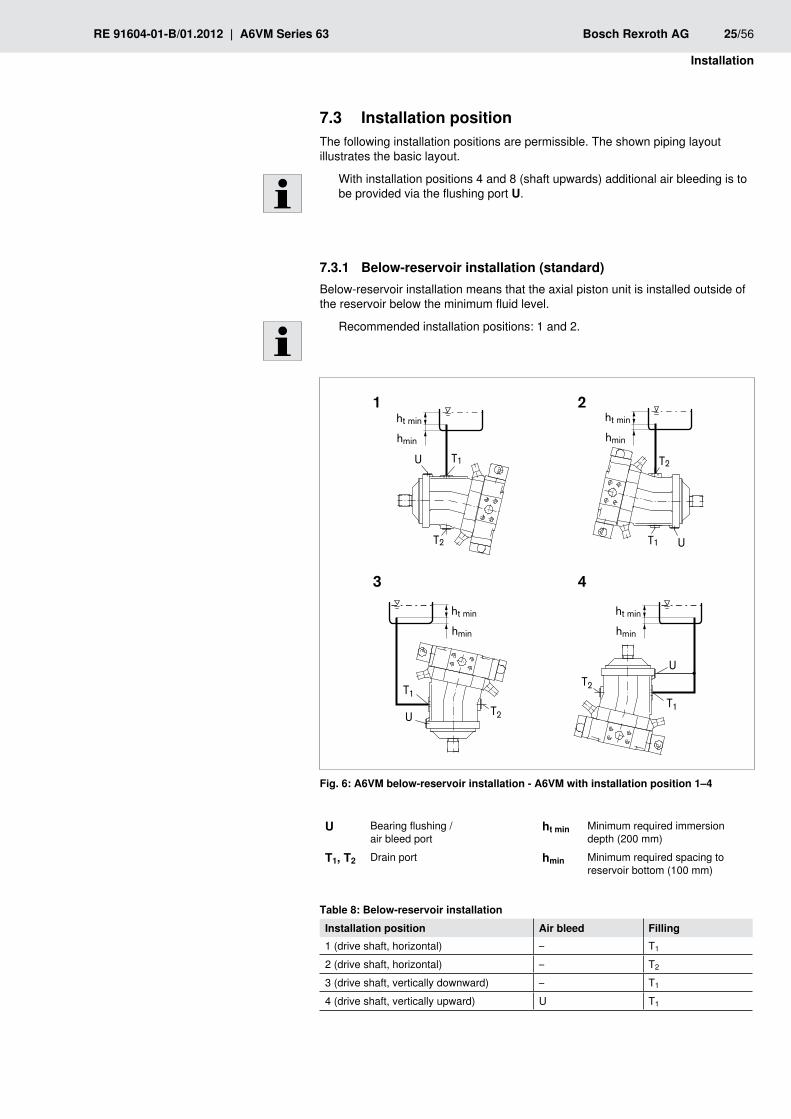
Installation position7.3 The following installation positions are permissible. The shown piping layout illustrates the basic layout.
With installation positions 4 and 8 (shaft upwards) additional air bleeding is to be provided via the flushing port U.
7.3.1 Below-reservoir installation (standard)Below-reservoir installation means that the axial piston unit is installed outside of the reservoir below the minimum fluid level.
Recommended installation positions: 1 and 2.
ht min
hmin
ht min
hmin
ht min
hmin
ht min
hmin
1 2
3 4
U T1
T2
T2
UT1
U T2
T1T2
U
T1
A6VM below-reservoir installation - A6VM with installation position 1–4Fig. 6:
U Bearing flushing / air bleed port
ht min Minimum required immersion depth (200 mm)
T1, T2 Drain port hmin Minimum required spacing to reservoir bottom (100 mm)
Below-reservoir installationTable 8: Installation position Air bleed Filling1 (drive shaft, horizontal) – T1
2 (drive shaft, horizontal) – T2
3 (drive shaft, vertically downward) – T1
4 (drive shaft, vertically upward) U T1
26/56 Bosch Rexroth AG A6VM Series 63 | RE 91604-01-B/01.2012
Installation
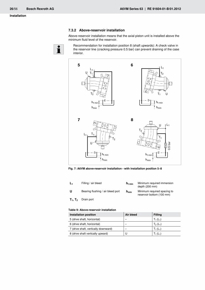
Above-reservoir installation7.3.2 Above-reservoir installation means that the axial piston unit is installed above the minimum fluid level of the reservoir.
Recommendation for installation position 8 (shaft upwards): A check valve in the reservoir line (cracking pressure 0.5 bar) can prevent draining of the case interior.
L1
ht min
hmin
L1
ht min
hmin
L1
ht min
hmin
L1
0.5
bar
ht min
hmin
5 6
7 8
T2
T1 U
T1
U
T2
T2
U
T1
U T1
T2
A6VM above-reservoir installation - with installation position 5–8Fig. 7:
l1 Filling / air bleed ht min Minimum required immersion depth (200 mm)
U Bearing flushing / air bleed port hmin Minimum required spacing to reservoir bottom (100 mm)
T1, T2 Drain port
Above-reservoir installationTable 9: Installation position Air bleed Filling5 (drive shaft, horizontal) – T1 (L1)6 (drive shaft, horizontal) – T2 (L1)7 (drive shaft, vertically downward) – T1 (L1)8 (drive shaft vertically upward) U T1 (L1)
RE 91604-01-B/01.2012 | A6VM Series 63 Bosch Rexroth AG 27/56
Installation
Installing the axial piston unit7.4
7.4.1 Preparation
Compare the material number and designation (ordering code) with the details 1. in the order confirmation.
If the material number for the axial piston unit does not correspond to the one in the order confirmation, contact Bosch Rexroth Service for clarification, see chapter "10.5 Spare parts" for address.
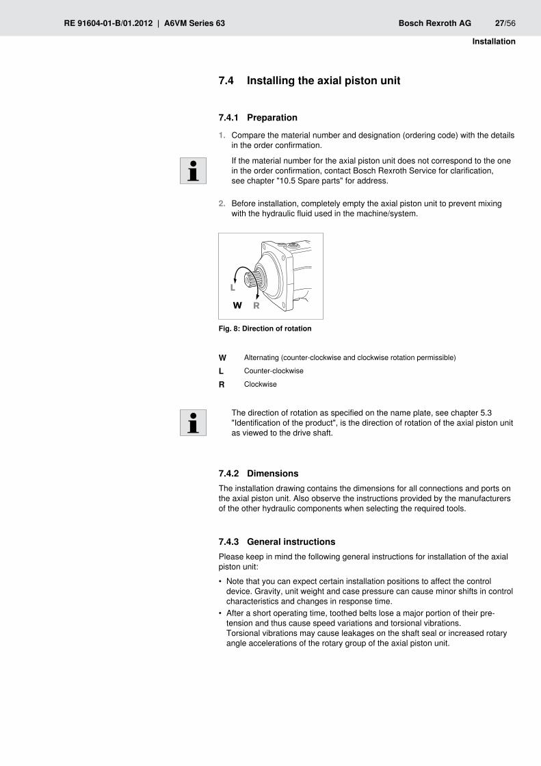
Before installation, completely empty the axial piston unit to prevent mixing 2. with the hydraulic fluid used in the machine/system.
L
RW
Fig. 8: Direction of rotation
w Alternating (counter-clockwise and clockwise rotation permissible)
l Counter-clockwise
R Clockwise
The direction of rotation as specified on the name plate, see chapter 5.3 "Identification of the product", is the direction of rotation of the axial piston unit as viewed to the drive shaft.
7.4.2 DimensionsThe installation drawing contains the dimensions for all connections and ports on the axial piston unit. Also observe the instructions provided by the manufacturers of the other hydraulic components when selecting the required tools.
7.4.3 General instructionsPlease keep in mind the following general instructions for installation of the axial piston unit:
Note that you can expect certain installation positions to affect the control •device. Gravity, unit weight and case pressure can cause minor shifts in control characteristics and changes in response time.After a short operating time, toothed belts lose a major portion of their pre- •tension and thus cause speed variations and torsional vibrations. Torsional vibrations may cause leakages on the shaft seal or increased rotary angle accelerations of the rotary group of the axial piston unit.
28/56 Bosch Rexroth AG A6VM Series 63 | RE 91604-01-B/01.2012
Installation
V-belt drives are also critical with respect to speed variations and torsional •vibration. These can also lead to leakages on the shaft seal ring. An automatic tensioning device can lessen the speed variations and vibrations and thus avoid consequential damage.
Always use an automatic tensioning device when using toothed belts or –V-belts to transfer the input or output drive.
On the input or output drive of an axial piston unit, a cardan shaft may cause •vibrations and impermissible rotary angle accelerations. Depending on the frequency and temperature, they may result in leakage on the shaft seal and damage to the rotary group.For combinations of multiple units, make sure that the respective case pressure •in each unit is not exceeded. In the event of pressure differences at the drain ports of the units, the shared drain line must be changed so that the minimum permissible case pressure of all connected units is not exceeded in any situation. If this is not possible, separate drain lines must be laid if necessary.
The installation method for the axial piston unit depends on the connecting elements to the output side. The following descriptions explain the installation of the axial piston unit:
with a coupling •on a gearbox •
7.4.4 Installation with couplingThe method for installing the axial piston unit with a coupling is described below:
nOTE! Danger from improper handling!Product can be damaged!
Do not install the coupling hub onto the drive shaft of the axial piston unit by fstriking it.
Install the specified coupling half onto the drive shaft of the axial piston unit 1. according to the instructions of the coupling manufacturer.
The drive shaft of the axial piston unit is equipped with a threaded bore. Use this threaded bore to pull the coupling element onto the drive shaft. The size of the threaded bore can be seen in the installation drawing.
Clamp the coupling hub onto the drive shaft or ensure permanent lubrication 2. of the drive shaft. This prevents the formation of frictional corrosion and the associated wear.
Transport the axial piston unit to the installation location.3.
Remove dirt and contaminants from the installation location.4.
Install the coupling on the drive shaft of the machine/system in accordance 5. with the specifications provided by the coupling manufacturer.
The axial piston unit may not be bolted down until the coupling has been correctly installed.
Fix the axial piston unit at the installation location.6.
Align the drive shaft of the axial piston unit and the drive shaft of the machine 7. or system so that there is no angular deviation.
Make sure that no impermissible axial and radial forces act on the drive shaft.8.
RE 91604-01-B/01.2012 | A6VM Series 63 Bosch Rexroth AG 29/56
Installation
Details on the required tools and tightening torques for the mounting bolts are 9. available from the machine/system manufacturer.
When using flexible couplings, check that the drive is free of resonance after 10. completing the installation.
7.4.5 Installation on a gearboxThe installation layout for the axial piston unit on a gearbox is described below.After installing on a gearbox, the axial piston unit is covered and is difficult to access:
Therefore, before installing, make sure that the centering spigot centers the faxial piston unit (observe tolerances) and that no impermissible axial or radial forces act on the drive shaft of the axial piston unit (installation length).Protect the drive shaft against frictional corrosion by providing permanent flubrication.Fix the axial piston unit at the installation location. f
No gearing forces higher than the permissible axial and radial forces are to act on the shaft, if necessary the gear wheel must be supported separately at the gearbox output.
Installation with cardan shaft7.4.6 To be connected around the axial piston unit with a cardan shaft:
Position the axial piston unit close to the specified installation location. 1. It should allow enough space for the cardan shaft to fit through on both sides.
Join the cardan shaft to the drive shaft of the machine/system.2.
Push the axial piston unit to the cardan shaft and join the cardan shaft to the 3. output shaft of the axial piston unit.
Bring the axial piston unit to the installation position and secure. Details on the 4. required tools and breakaway torques for the mounting bolts can be obtained from the system manufacturer if required.
Completing 7.4.7 installation
Remove any mounted transport screws.1.
CAUTIOn! Operation with protective plug!Operating the axial piston unit with protective plugs may result in injuries or damage to the axial piston unit.
Before commissioning, remove all protective plugs and replace them with fsuitable, pressure-proof, metal threaded plugs.
For attachment via gear wheel or helically-toothed shaft
30/56 Bosch Rexroth AG A6VM Series 63 | RE 91604-01-B/01.2012
Installation
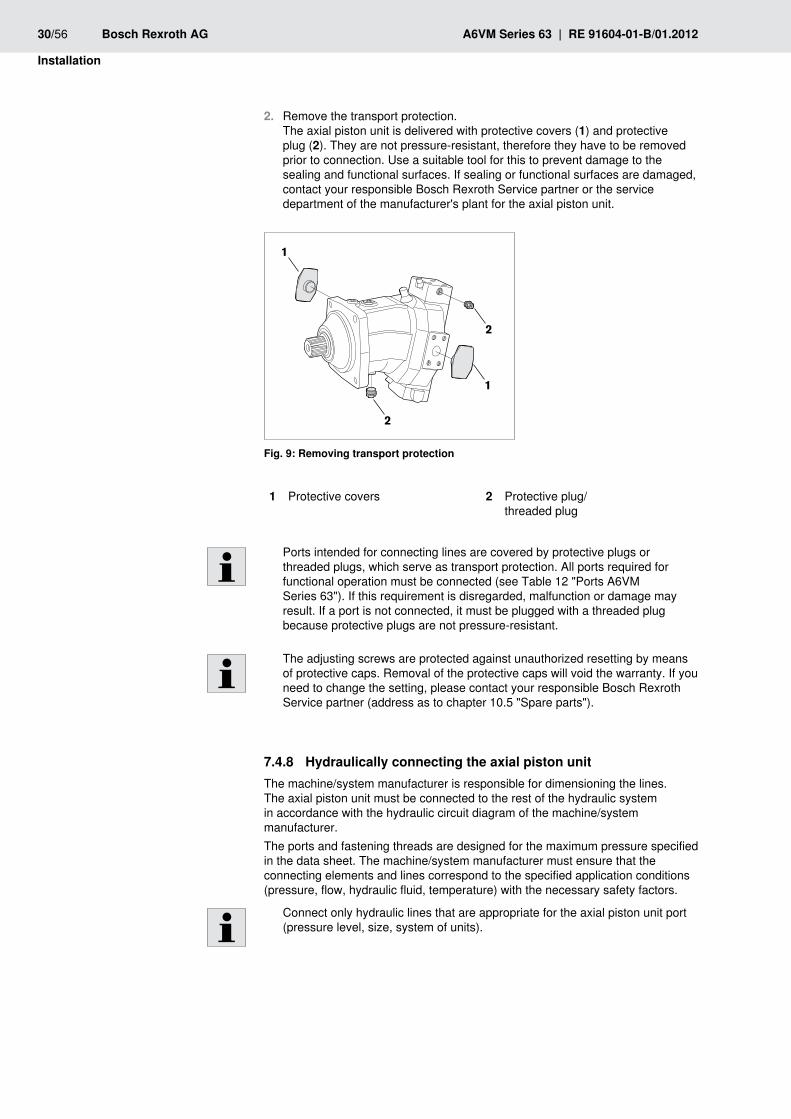
Remove the transport protection. 2. The axial piston unit is delivered with protective covers (1) and protective plug (2). They are not pressure-resistant, therefore they have to be removed prior to connection. Use a suitable tool for this to prevent damage to the sealing and functional surfaces. If sealing or functional surfaces are damaged, contact your responsible Bosch Rexroth Service partner or the service department of the manufacturer's plant for the axial piston unit.
1
2
2
1
Fig. 9: Removing transport protection
Protective covers1 Protective plug/ 2 threaded plug
Ports intended for connecting lines are covered by protective plugs or threaded plugs, which serve as transport protection. All ports required for functional operation must be connected (see Table 12 "Ports A6VM Series 63"). If this requirement is disregarded, malfunction or damage may result. If a port is not connected, it must be plugged with a threaded plug because protective plugs are not pressure-resistant.
The adjusting screws are protected against unauthorized resetting by means of protective caps. Removal of the protective caps will void the warranty. If you need to change the setting, please contact your responsible Bosch Rexroth Service partner (address as to chapter 10.5 "Spare parts").
Hydraulically connecting the axial piston unit7.4.8 The machine/system manufacturer is responsible for dimensioning the lines. The axial piston unit must be connected to the rest of the hydraulic system in accordance with the hydraulic circuit diagram of the machine/system manufacturer.The ports and fastening threads are designed for the maximum pressure specified in the data sheet. The machine/system manufacturer must ensure that the connecting elements and lines correspond to the specified application conditions (pressure, flow, hydraulic fluid, temperature) with the necessary safety factors.
Connect only hydraulic lines that are appropriate for the axial piston unit port (pressure level, size, system of units).
RE 91604-01-B/01.2012 | A6VM Series 63 Bosch Rexroth AG 31/56
Installation
Observe the following notes when routing the pressure and reservoir lines.
Lines and hoses must be installed without pre-charge pressure, so that no •further mechanical forces are applied during operation that will reduce the service life of the axial piston unit and, if applicable, the entire machine/system.Use suitable seals as sealing material. •Pressure line •
For the pressure lines, use only pipes, hoses and connecting elements –rated for the operating pressure range specified in data sheet RE 91604 (see Table 12).
Drain line •Always route the reservoir lines so that the case is constantly filled with –hydraulic fluid and to ensure that no air gets through the shaft seal even during extended standstill periods.The case internal pressure must not exceed the limit values listed for the axial –piston unit in the data sheet under any operating conditions.The reservoir line joint in the reservoir must always be below the minimum –fluid level under all conditions (see chapter 7.3 "Installation position").
If the axial piston unit is equipped with installed screw fittings, these must not •be unscrewed. Screw the threaded plug of the fitting directly into the installed screw fitting.
Axial piston units are employed in regions using the metric measuring system, in regions using the Anglo-American (imperial) measuring system and in regions using the Japanese (Japan Industrial Standard) measuring system.Both the system of units as well as the size of female thread and threaded plugs (e.g. locking screw) must match.Due to the limited options for visually detecting differences, there is a risk of mix-ups.
wARnInG! Leaking or popped-out threaded plugs!If a threaded plug which is of a different measurement system and size with respect to the female thread is pressurized, the threaded plug may loosen itself or even be ejected from the hole in a projectile-like manner. This can result in serious injury and damage to equipment. Hydraulic fluid can be discharged from this leakage point.
Use the drawings (installation drawing) to determine the required threaded fplug for each fitting.Make certain that there are no mix-ups when installing fittings, mounting bolts fand locking screws.For all female threads, use a threaded plug from the same system of units and fof the correct size.
notes on routing the lines
Risk of mix-ups with threaded connections
32/56 Bosch Rexroth AG A6VM Series 63 | RE 91604-01-B/01.2012
Installation
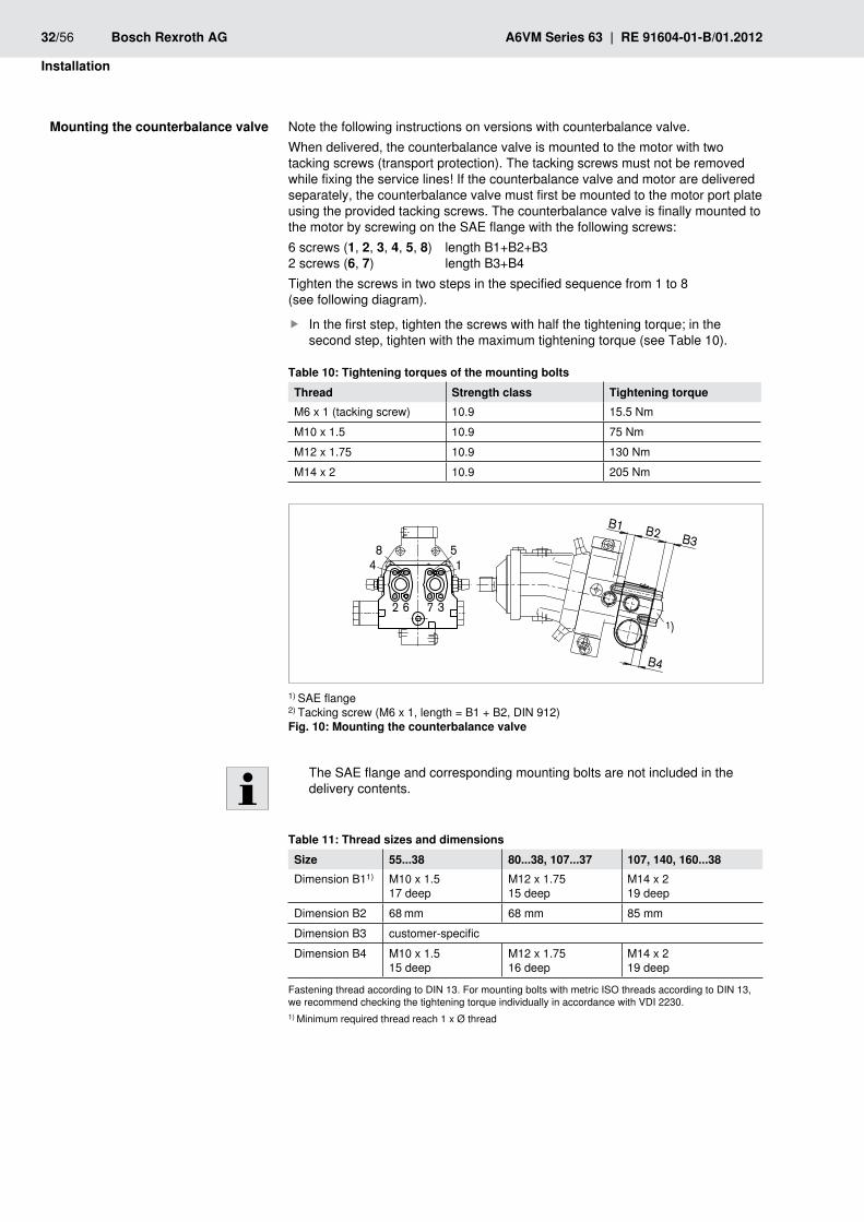
Note the following instructions on versions with counterbalance valve.When delivered, the counterbalance valve is mounted to the motor with two tacking screws (transport protection). The tacking screws must not be removed while fixing the service lines! If the counterbalance valve and motor are delivered separately, the counterbalance valve must first be mounted to the motor port plate using the provided tacking screws. The counterbalance valve is finally mounted to the motor by screwing on the SAE flange with the following screws:6 screws (1, 2, 3, 4, 5, 8) length B1+B2+B3 2 screws (6, 7) length B3+B4Tighten the screws in two steps in the specified sequence from 1 to 8 (see following diagram).
In the first step, tighten the screws with half the tightening torque; in the fsecond step, tighten with the maximum tightening torque (see Table 10).
Tightening torques of the mounting boltsTable 10: Thread Strength class Tightening torqueM6 x 1 (tacking screw) 10.9 15.5 NmM10 x 1.5 10.9 75 NmM12 x 1.75 10.9 130 NmM14 x 2 10.9 205 Nm
B4
B1 B2
1)
B358
4
3762
1
1) SAE flange2) Tacking screw (M6 x 1, length = B1 + B2, DIN 912)
Mounting the counterbalance valveFig. 10:
The SAE flange and corresponding mounting bolts are not included in the delivery contents.
Thread sizes and dimensionsTable 11: Size 55...38 80...38, 107...37 107, 140, 160...38Dimension B11) M10 x 1.5
17 deepM12 x 1.7515 deep
M14 x 219 deep
Dimension B2 68 mm 68 mm 85 mmDimension B3 customer-specificDimension B4 M10 x 1.5
15 deepM12 x 1.7516 deep
M14 x 219 deep
Fastening thread according to DIN 13. For mounting bolts with metric ISO threads according to DIN 13, we recommend checking the tightening torque individually in accordance with VDI 2230.1) Minimum required thread reach 1 x Ø thread
Mounting the counterbalance valve
RE 91604-01-B/01.2012 | A6VM Series 63 Bosch Rexroth AG 33/56
Installation
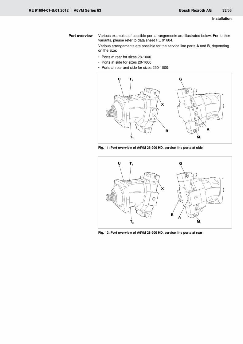
Various examples of possible port arrangements are illustrated below. For further variants, please refer to data sheet RE 91604.Various arrangements are possible for the service line ports A and B, depending on the size:
Ports at rear for sizes 28-1000 •Ports at side for sizes 28-1000 •Ports at rear and side for sizes 250-1000 •
A
U T1
T2
X
G
M1
B
Port overview of A6VM 28-200 HD, service line ports at sideFig. 11:
A
U T1
T2
X
G
M1
B
Port overview of A6VM 28-200 HD, service line ports at rearFig. 12:
Port overview
34/56 Bosch Rexroth AG A6VM Series 63 | RE 91604-01-B/01.2012
Installation
B
U
T2
T2
X
G
M
A
MA
MB
T1
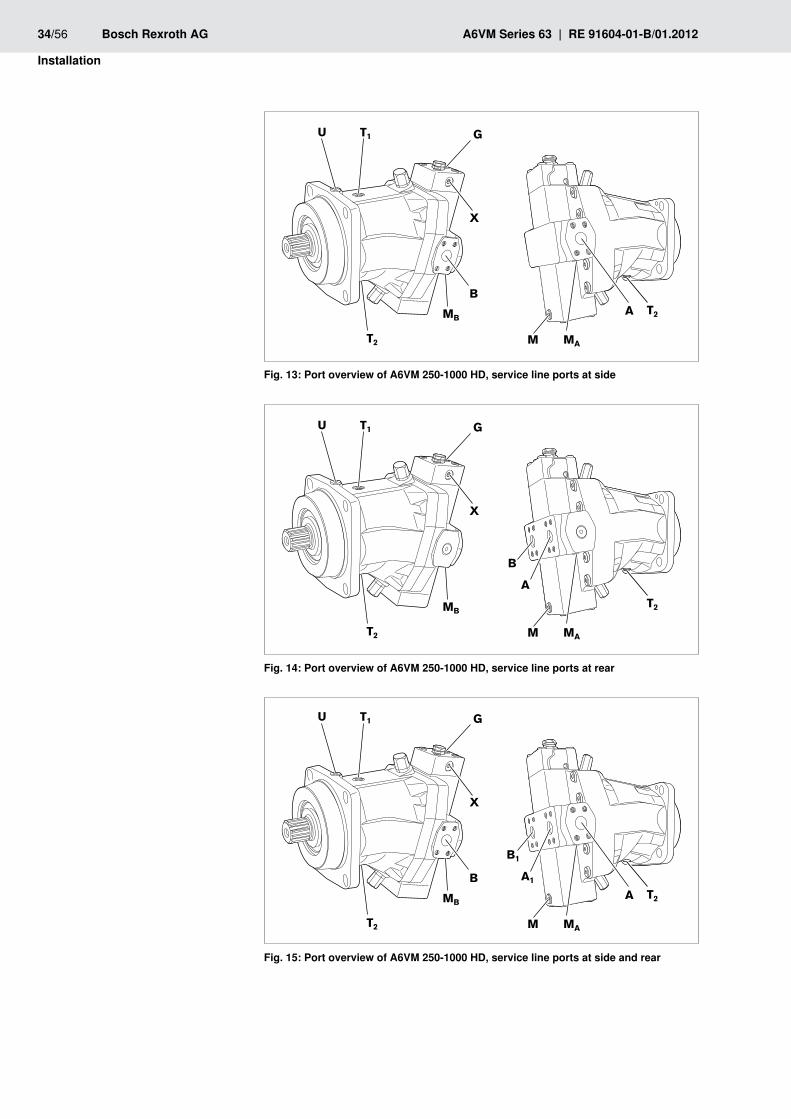
Port overview of A6VM 250-1000 HD, service line ports at sideFig. 13:
U
T2
T2
X
G
M
B
A
MA
MB
T1
Port overview of A6VM 250-1000 HD, service line ports at rearFig. 14:
B
U
T2
T2
X
G
M
A
B1
A1
MA
MB
T1
Port overview of A6VM 250-1000 HD, service line ports at side and rearFig. 15:
RE 91604-01-B/01.2012 | A6VM Series 63 Bosch Rexroth AG 35/56
Installation
U T1
T2
B
M1
G
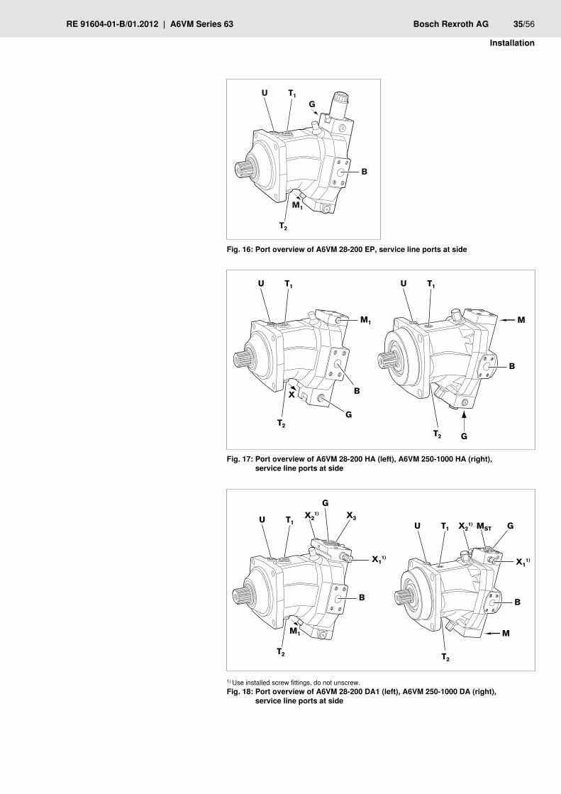
Port overview of A6VM 28-200 EP, service line ports at sideFig. 16:
U T1
X
T2
M1
B
G
G
U T1
M
B
T2
Port overview of A6VM 28-200 HA (left), A6VM 250-1000 HA (right), Fig. 17: service line ports at side
U T1
T2
X11)
B
M1
GX2
1) X3
U T1
X11)
B
T2
M
X21) MST G
1) Use installed screw fittings, do not unscrew. Port overview of A6VM 28-200 DA1 (left), A6VM 250-1000 DA (right), Fig. 18: service line ports at side
36/56 Bosch Rexroth AG A6VM Series 63 | RE 91604-01-B/01.2012
Installation
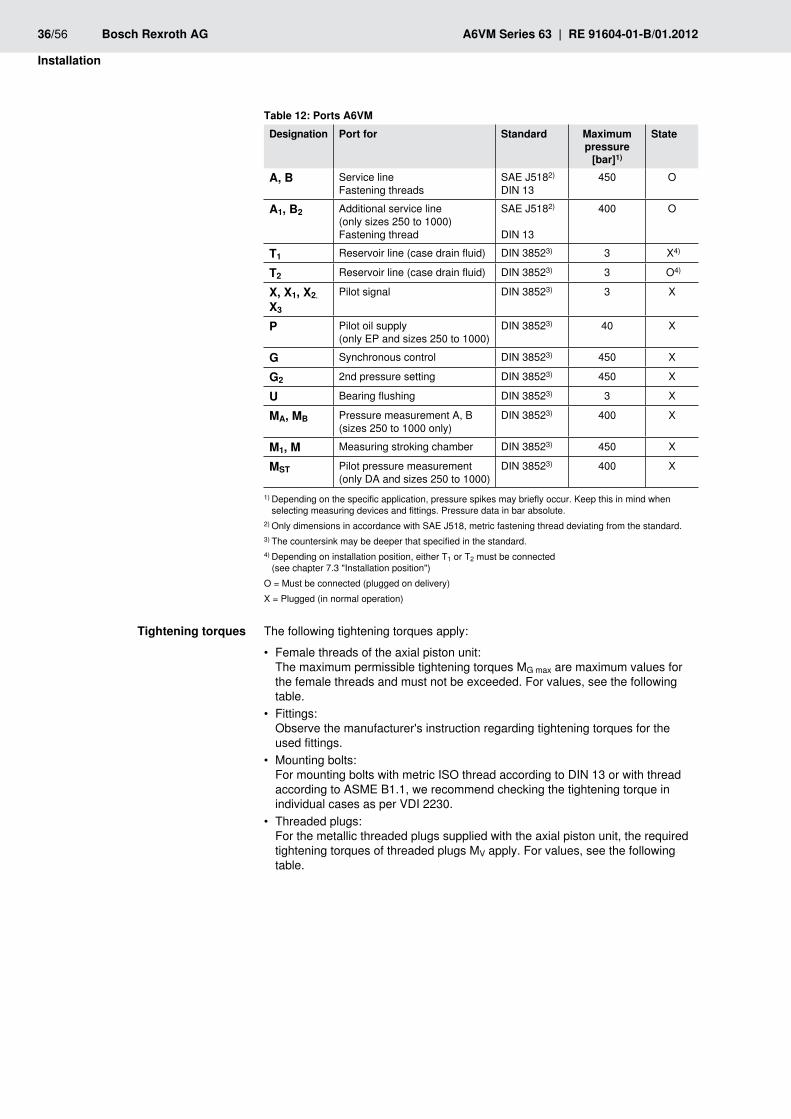
Ports A6VMTable 12: Designation Port for Standard Maximum
pressure [bar]1)
State
A, B Service lineFastening threads
SAE J5182)
DIN 13450 O
A1, B2 Additional service line (only sizes 250 to 1000) Fastening thread
SAE J5182)
DIN 13
400 O
T1 Reservoir line (case drain fluid) DIN 38523) 3 X4)
T2 Reservoir line (case drain fluid) DIN 38523) 3 O4)
X, X1, X2, X3
Pilot signal DIN 38523) 3 X
P Pilot oil supply (only EP and sizes 250 to 1000)
DIN 38523) 40 X
G Synchronous control DIN 38523) 450 X
G2 2nd pressure setting DIN 38523) 450 X
U Bearing flushing DIN 38523) 3 X
MA, MB Pressure measurement A, B (sizes 250 to 1000 only)
DIN 38523) 400 X
M1, M Measuring stroking chamber DIN 38523) 450 X
MST Pilot pressure measurement (only DA and sizes 250 to 1000)
DIN 38523) 400 X
1) Depending on the specific application, pressure spikes may briefly occur. Keep this in mind when selecting measuring devices and fittings. Pressure data in bar absolute.
2) Only dimensions in accordance with SAE J518, metric fastening thread deviating from the standard.3) The countersink may be deeper that specified in the standard.4) Depending on installation position, either T1 or T2 must be connected (see chapter 7.3 "Installation position")O = Must be connected (plugged on delivery)X = Plugged (in normal operation)
The following tightening torques apply:
Female threads of the axial piston unit: •The maximum permissible tightening torques MG max are maximum values for the female threads and must not be exceeded. For values, see the following table.Fittings: •Observe the manufacturer's instruction regarding tightening torques for the used fittings.Mounting bolts: •For mounting bolts with metric ISO thread according to DIN 13 or with thread according to ASME B1.1, we recommend checking the tightening torque in individual cases as per VDI 2230.Threaded plugs: •For the metallic threaded plugs supplied with the axial piston unit, the required tightening torques of threaded plugs MV apply. For values, see the following table.
Tightening torques
RE 91604-01-B/01.2012 | A6VM Series 63 Bosch Rexroth AG 37/56
Installation
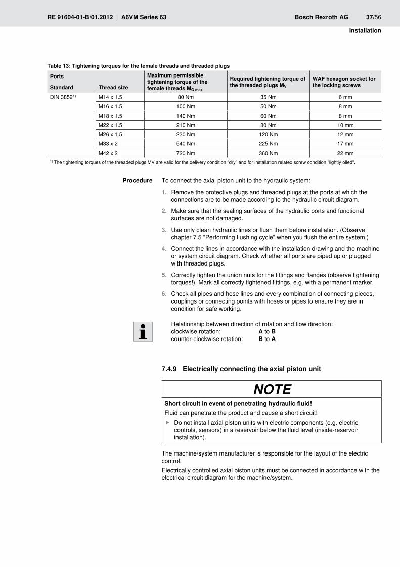
Tightening torques for the female threads and threaded plugsTable 13:
Ports Maximum permissible tightening torque of the female threads MG max
Required tightening torque of the threaded plugs MV
wAF hexagon socket for the locking screwsStandard Thread size
DIN 38521) M14 x 1.5 80 Nm 35 Nm 6 mmM16 x 1.5 100 Nm 50 Nm 8 mmM18 x 1.5 140 Nm 60 Nm 8 mmM22 x 1.5 210 Nm 80 Nm 10 mmM26 x 1.5 230 Nm 120 Nm 12 mmM33 x 2 540 Nm 225 Nm 17 mmM42 x 2 720 Nm 360 Nm 22 mm
1) The tightening torques of the threaded plugs MV are valid for the delivery condition "dry" and for installation related screw condition "lightly oiled".
To connect the axial piston unit to the hydraulic system:
Remove the protective plugs and threaded plugs at the ports at which the 1. connections are to be made according to the hydraulic circuit diagram.
Make sure that the sealing surfaces of the hydraulic ports and functional 2. surfaces are not damaged.
Use only clean hydraulic lines or flush them before installation. (Observe 3. chapter 7.5 "Performing flushing cycle" when you flush the entire system.)
Connect the lines in accordance with the installation drawing and the machine 4. or system circuit diagram. Check whether all ports are piped up or plugged with threaded plugs.
Correctly tighten the union nuts for the fittings and flanges (observe tightening 5. torques!). Mark all correctly tightened fittings, e.g. with a permanent marker.
Check all6. pipes and hose lines and every combination of connecting pieces, couplings or connecting points with hoses or pipes to ensure they are in condition for safe working.
Relationship between direction of rotation and flow direction: clockwise rotation: A to B counter-clockwise rotation: B to A
Electrically connecting the axial piston unit7.4.9
NOTEShort circuit in event of penetrating hydraulic fluid!Fluid can penetrate the product and cause a short circuit!
Do not install axial piston units with electric components (e.g. electric fcontrols, sensors) in a reservoir below the fluid level (inside-reservoir installation).
The machine/system manufacturer is responsible for the layout of the electric control.Electrically controlled axial piston units must be connected in accordance with the electrical circuit diagram for the machine/system.
Procedure
38/56 Bosch Rexroth AG A6VM Series 63 | RE 91604-01-B/01.2012
Installation
For axial piston units with electrical control and/or mounted sensors, please comply with the details given in data sheet RE 91604, e.g.:
the permissible voltage range •the permissible current •correct connection •the recommended electrical control units •
Exact details on the connector, type of protection and matching mating connector can also be found in data sheet RE 91604. The mating connector is not included in the delivery contents.
Switch off power supply to the relevant system component.1.
Electrically connect the axial piston unit (12 or 24V). Before connecting, check 2. that the connector including all seals are intact.
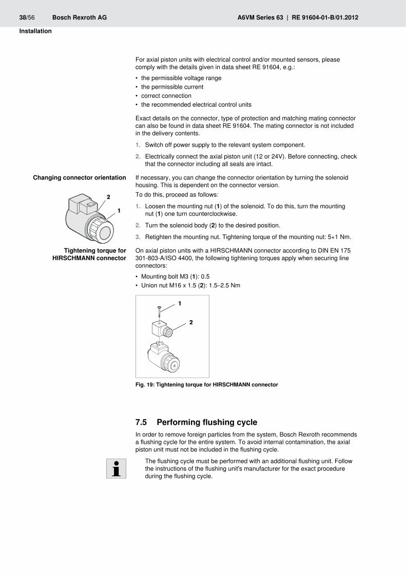
If necessary, you can change the connector orientation by turning the solenoid housing. This is dependent on the connector version.To do this, proceed as follows:
Loosen the mounting nut (1. 1) of the solenoid. To do this, turn the mounting nut (1) one turn counterclockwise.
Turn the solenoid body (2. 2) to the desired position.
Retighten the mounting nut. Tightening torque of the mounting nut: 5+1 Nm.3.
On axial piston units with a HIRSCHMANN connector according to DIN EN 175 301-803-A/ISO 4400, the following tightening torques apply when securing line connectors:
Mounting bolt M3 ( • 1): 0.5Union nut M16 x 1.5 ( • 2): 1.5–2.5 Nm
1
2
Tightening torque for HIRSCHMAnn connectorFig. 19:
7.5 Performing flushing cycleIn order to remove foreign particles from the system, Bosch Rexroth recommends a flushing cycle for the entire system. To avoid internal contamination, the axial piston unit must not be included in the flushing cycle.
The flushing cycle must be performed with an additional flushing unit. Follow the instructions of the flushing unit's manufacturer for the exact procedure during the flushing cycle.
Changing connector orientation
2
1
Tightening torque for HIRSCHMAnn connector
RE 91604-01-B/01.2012 | A6VM Series 63 Bosch Rexroth AG 39/56
Commissioning
8 Commissioning
wARnInGDanger while working in the danger zone of a machine/system!Danger to life, risk of injury or serious injuries!
Pay attention to and rectify potential danger sources before operating the faxial piston unit.Nobody may stand in the danger zone of the machine/system. fThe emergency stop button for the machine/system must be within the foperator’s reach.Always follow the instructions of the machine/system manufacturer during fcommissioning.
CAUTIOnCommissioning of an incorrectly installed product!Risk of injury and damage to equipment!You can injure yourself on incorrectly installed products or damage the product.
Make sure that all electrical and hydraulic ports are connected or plugged. fOnly commission a completely installed product. f
First 8.1 commissioningDuring all work for commissioning the axial piston unit, observe the general safety instructions and intended use in chapter 2 "Safety instructions".
Connect the gage for the operating pressure and case pressure to the fspecified measuring points on the axial piston unit or in the hydraulic system, to check the technical data at first operation.During the commissioning process, monitor the temperature of the hydraulic ffluid in the reservoir to ensure that it lies within the permissible viscosity limits.
Filling the 8.1.1 axial piston unitProfessional filling and air bleeding is necessary to prevent damage to the axial piston unit and to maintain correct function.
The axial piston unit should be filled with a filling unit (10 µm filter grade). The axial piston unit must not be operated while it is being filled by the filling unit.
Use only a hydraulic fluid that conforms to the following requirements:You can find details of the minimum requirements on hydraulic fluids in Bosch Rexroth data sheets RE 90220, RE 90221, RE 90222 and RE 90223. You can find the title of the data sheets in table 1 "Required and supplementary documentation". You can find details of permissible and optimal viscosity in data sheet RE 91604.
40/56 Bosch Rexroth AG A6VM Series 63 | RE 91604-01-B/01.2012
Commissioning
To ensure the functional reliability of the axial piston unit, cleanliness level 20/18/15 according to at least ISO 4406 is necessary for the hydraulic fluid. At very high hydraulic fluid temperatures (+90 °C to maximum +115 °C), a cleanliness level of at least 19/17/14 according to ISO 4406 is necessary. For permissible temperatures, see the data sheet RE 91604.
Place a drip tray under the axial piston unit to collect any hydraulic fluid that 1. may escape.
nOTE! Contaminated hydraulic fluid!The cleanliness levels of hydraulic fluids on delivery do not normally conform to the requirements for our components.
Use a suitable filter system to filter hydraulic fluids during filling to minimize fsolid impurities and water in the hydraulic system.
Fill and air bleed the axial piston unit via the appropriate ports, see chapter 7.3 2. "Installation position". The hydraulic lines of the system must also be filled. For installation position "drive shaft upwards": Air bleed the case via port "U". Air bleeding is not necessary for other installation positions; the case is bled automatically via the case drain line.
nOTE! Damage to equipment due to improper lubrication!Product can be damaged or destroyed!
When using a shut-off valve in the reservoir line, make sure that the input of fthe axial piston unit can only be started when the shut-off valves are open.
When using a shut-off valve in the reservoir line, only operate the axial piston 3. unit when the shut-off valves are open.
Testing the hydraulic fluid supply8.1.2 The axial piston unit must always have a sufficient supply of hydraulic fluid. For this reason, the supply of hydraulic fluid must be ensured at the start of the commissioning process.When you test the hydraulic fluid supply, constantly monitor the noise development and check the hydraulic fluid level in the reservoir. If the axial piston unit becomes louder (cavitation) or the case drain fluid is discharged with bubbles, this is an indication that the axial piston unit is not being sufficiently supplied with hydraulic fluid.Notes on troubleshooting can be found in chapter 14 "Troubleshooting".To test the hydraulic fluid supply:
Allow the axial piston unit to run at low speed and without load. Pay attention 1. to leakage and noise.
Check the axial piston unit’s reservoir line during the test. The case drain fluid 2. should not contain any bubbles.
Increase the load and check whether the operating pressure rises as 3. expected.
Carry out a leak test to ensure that the hydraulic system is sealed and can 4. withstand the maximum pressure.
Check the case drain pressure at port 5. T1, T2 or U at maximum pressure. Refer to data sheet RE 91604 for the permissible value.
RE 91604-01-B/01.2012 | A6VM Series 63 Bosch Rexroth AG 41/56
Commissioning
8.1.3 Performing functional test
wARnInGIncorrectly connected axial piston unit!Mixing up the ports will lead to malfunctions (e.g. lift instead of lower) and thus to corresponding danger to persons and equipment!
Before the functional test, check whether the piping specified in the hydraulic fcircuit diagram has been installed.
Once you have tested the hydraulic fluid supply, you must perform a functional test on the machine/system. The functional test should be performed according to the instructions of the machine/system manufacturer.The axial piston unit is checked for functional capability before delivery according to the technical data. During commissioning, it must be ensured that the axial piston unit was installed properly in the machine/system.
After starting the engine, check in particular the specified pressures, fe.g. system pressure, boost pressure and case pressure.If necessary, disconnect the gage and plug the ports with threaded plugs. f
8.2 Running-in phase
NOTEDamage to equipment by insufficient viscosity!An increased hydraulic fluid temperature may reduce the viscosity values by too much and damage the product!
Monitor the operating temperature during the running-in phase, e.g. by fmeasuring the case drain temperature.Reduce the loading (pressure, rpm) of the axial piston unit if impermissible foperating temperatures and/or viscosities occur.Operating temperatures that are too high indicate faults that have to be fanalyzed and cleared.
The bearings and sliding surfaces are subject to a running-in phase. The increased friction at the start of the running-in phase results in increased heat development which decreases with increasing operating hours. The volumetric and mechanical-hydraulic efficiency increases as well through the conclusion of the running-in phase of approx. 10 operating hours.To ensure that contamination in the hydraulic system does not damage the axial piston unit, Bosch Rexroth recommends the following procedure after the running-in phase:
After the running-in phase, have a hydraulic fluid specimen analyzed for the frequired cleanliness level.Change the hydraulic fluid if the required cleanliness level is not reached. If fa laboratory test is not carried out after the running-in phase, Bosch Rexroth recommends the hydraulic fluid be changed.

42/56 Bosch Rexroth AG A6VM Series 63 | RE 91604-01-B/01.2012
Commissioning
8.3 Recommissioning after standstillDepending on the installation conditions and ambient conditions, changes may occur in the hydraulic system which make recommissioning necessary.Among others, the following criteria may make recommissioning necessary:
Air and/or water in the hydraulic system •Old hydraulic fluid •Other contamination •
Before recommissioning, proceed as described in chapter 8.1 f"First commissioning".

RE 91604-01-B/01.2012 | A6VM Series 63 Bosch Rexroth AG 43/56
Operation
9 OperationThe product is a component which requires no settings or changes during operation. For this reason, this chapter of the manual does not contain any information on adjustment options. Use the product only within the performance range provided in the technical data. The machine/system manufacturer is responsible for the proper project planning of the hydraulic system and its control.
44/56 Bosch Rexroth AG A6VM Series 63 | RE 91604-01-B/01.2012
Maintenance and repair
10 Maintenance and repair
NOTEInspection and maintenance work carried out too late!Damage to equipment!
Carry out the specified inspection and maintenance work at the intervals fdescribed in this manual.
10.1 Cleaning and care
NOTEDamage to seals and electrical system by mechanical effects!The water jet of a power washer may damage the seals and electrical system of the axial piston unit!
Do not point the power washer at sensitive components, e.g. shaft seal, felectrical connections and components.
For cleaning and care of the axial piston unit, observe the following:
Check whether all seals and fittings on the connections are securely seated fto ensure that no moisture can penetrate into the axial piston unit during cleaning.Use only water and, if necessary, a mild detergent to clean the axial piston funit. Never use solvents or aggressive detergents.Remove coarse external dirt and keep sensitive and important components, fsuch as solenoids, valves, indicators and sensors, clean.
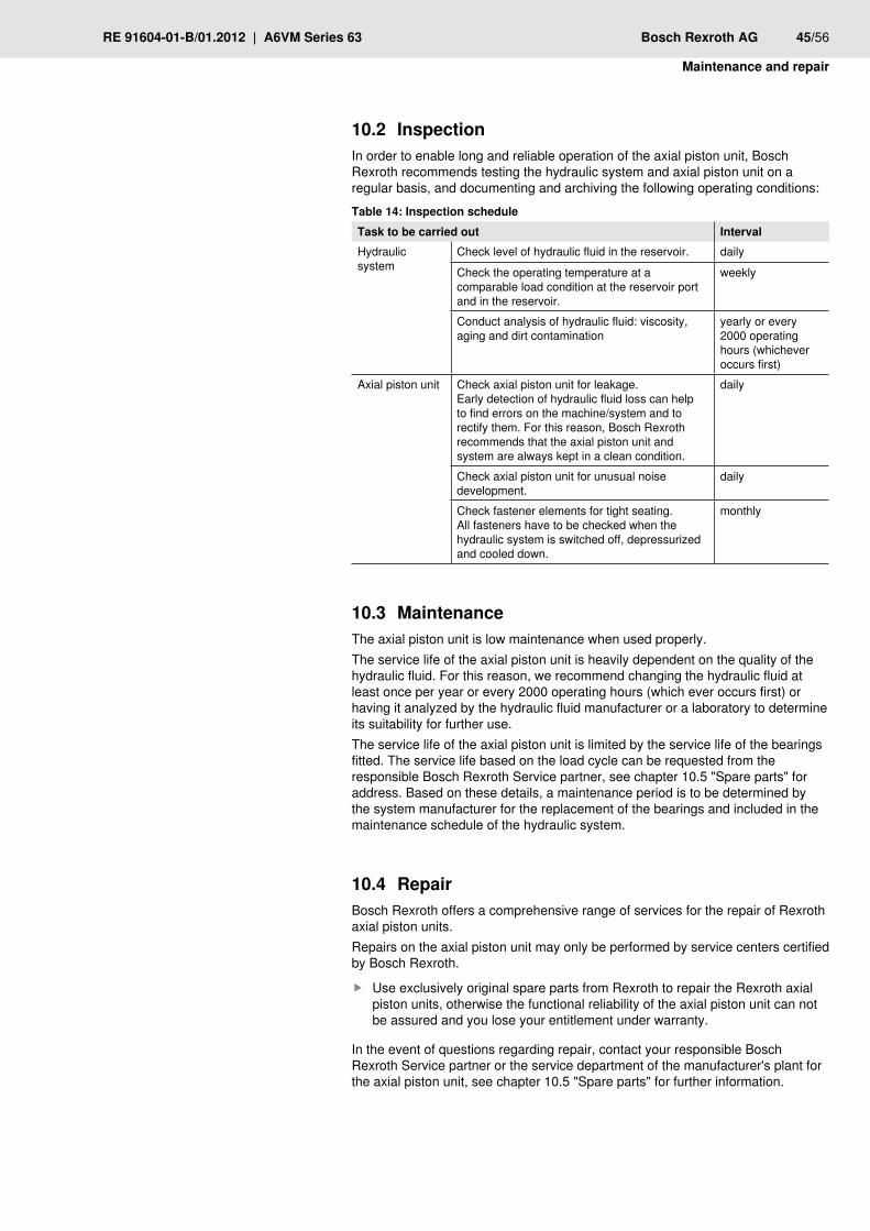
RE 91604-01-B/01.2012 | A6VM Series 63 Bosch Rexroth AG 45/56
Maintenance and repair
10.2 InspectionIn order to enable long and reliable operation of the axial piston unit, Bosch Rexroth recommends testing the hydraulic system and axial piston unit on a regular basis, and documenting and archiving the following operating conditions:
Inspection scheduleTable 14: Task to be carried out IntervalHydraulic system
Check level of hydraulic fluid in the reservoir. daily
Check the operating temperature at a comparable load condition at the reservoir port and in the reservoir.
weekly
Conduct analysis of hydraulic fluid: viscosity, aging and dirt contamination
yearly or every 2000 operating hours (whichever occurs first)
Axial piston unit Check axial piston unit for leakage. Early detection of hydraulic fluid loss can help to find errors on the machine/system and to rectify them. For this reason, Bosch Rexroth recommends that the axial piston unit and system are always kept in a clean condition.
daily
Check axial piston unit for unusual noise development.
daily
Check fastener elements for tight seating. All fasteners have to be checked when the hydraulic system is switched off, depressurized and cooled down.
monthly
10.3 MaintenanceThe axial piston unit is low maintenance when used properly.The service life of the axial piston unit is heavily dependent on the quality of the hydraulic fluid. For this reason, we recommend changing the hydraulic fluid at least once per year or every 2000 operating hours (which ever occurs first) or having it analyzed by the hydraulic fluid manufacturer or a laboratory to determine its suitability for further use.The service life of the axial piston unit is limited by the service life of the bearings fitted. The service life based on the load cycle can be requested from the responsible Bosch Rexroth Service partner, see chapter 10.5 "Spare parts" for address. Based on these details, a maintenance period is to be determined by the system manufacturer for the replacement of the bearings and included in the maintenance schedule of the hydraulic system.
10.4 RepairBosch Rexroth offers a comprehensive range of services for the repair of Rexroth axial piston units.Repairs on the axial piston unit may only be performed by service centers certified by Bosch Rexroth.
Use exclusively original spare parts from Rexroth to repair the Rexroth axial fpiston units, otherwise the functional reliability of the axial piston unit can not be assured and you lose your entitlement under warranty.
In the event of questions regarding repair, contact your responsible Bosch Rexroth Service partner or the service department of the manufacturer's plant for the axial piston unit, see chapter 10.5 "Spare parts" for further information.
46/56 Bosch Rexroth AG A6VM Series 63 | RE 91604-01-B/01.2012
Maintenance and repair
10.5 Spare parts
CAUTIOnUse of unsuitable spare parts!Spare parts that do not meet the technical requirements specified by Bosch Rexroth may cause personal injury or property damage!
Use exclusively original spare parts from Rexroth to repair the Rexroth axial fpiston units, otherwise the functional reliability of the axial piston unit can not be assured and you lose your entitlement under warranty.
The spare parts lists for axial piston units are order specific. When ordering spare parts, quote the material and serial number of the axial piston unit as well as the material numbers of the spare parts.Address all questions regarding spare parts to your responsible Bosch Rexroth Service partner or the service department of the manufacturer's plant for the axial piston unit. Details on the manufacture’s plant are available on the axial piston unit's name plate.
Bosch Rexroth AG Glockeraustraße 4 D-89275 Elchingen, Germany Tel. +49-7308-82-0 Fax +49-711-811-513-9382 [email protected]
Bosch Rexroth AG An den Kelterwiesen 14 72160 Horb a.N., Germany Tel. +49 (0) 74 51-92-0 Fax +49 (0) 711-811-513-93 82 [email protected] For the addresses of foreign subsidiaries, please refer to www.boschrexroth.com/addresses
RE 91604-01-B/01.2012 | A6VM Series 63 Bosch Rexroth AG 47/56
Removal and replacement
11 Removal and replacement
Required 11.1 toolsRemoval can be performed with standard tools. No special tools are necessary.
11.2 Preparing for removalDecommission the entire system as described in the instruction manual for the 1. machine or system.
Relieve pressure in the hydraulic system according to the instructions of the –machine or system manufacturer.Make sure that the relevant system components are not under pressure or –voltage.
Protect the complete system against being energized.2.
11.3 Removing the axial piston unitProceed as follows to remove the axial piston unit:
Check whether the hydraulic system is depressurized.1.
Allow the axial piston unit to cool down until it can be removed without danger.2.
For below-reservoir installation, before removing the axial piston unit from the 3. complete system, seal the connection to the reservoir or drain the reservoir.
Place a drip tray under the axial piston unit to collect any hydraulic fluid that 4. may escape.
Loosen the lines and collect the escaping hydraulic fluid in the drip tray.5.
Remove the axial piston unit. Use an appropriate lifting device.6.
Completely empty the axial piston unit.7.
Plug all openings.8.
Preparing the components for storage or 11.4 further use
Proceed as described in chapter "6.2 Storing the axial piston unit". f
48/56 Bosch Rexroth AG A6VM Series 63 | RE 91604-01-B/01.2012
Disposal
12 DisposalCareless disposal of the axial piston unit, the hydraulic fluid and the packaging material could lead to pollution of the environment.Observe the following points when disposing of the axial piston unit:
Completely empty the axial piston unit.1.
Dispose of the axial piston unit and packaging material in accordance with the 2. national regulations in your country.
Dispose of the hydraulic fluid according to the national regulations of your 3. country. Also observe the applicable safety data sheet for the hydraulic fluid.
Remove the axial piston unit into its individual parts and properly recycle these 4. parts.
Separate according to, for instance:5. Cast parts –Steel –Aluminum –Non-ferrous metal –Electronic waste –Plastic –Seals –
Extension and 13 conversionDo not modify the axial piston unit. This is also including a modification of the adjusting screws.
The Bosch Rexroth warranty only applies for the delivered configuration. In case of conversion or extension, the entitlement under warranty will be rendered void.
The adjusting screws are protected against unauthorized resetting by means of protective caps. Removal of the protective caps will void the warranty. If you need to change the setting, please contact your responsible Bosch Rexroth Service partner (address as to chapter 10.5 "Spare parts").
RE 91604-01-B/01.2012 | A6VM Series 63 Bosch Rexroth AG 49/56
Troubleshooting
14 TroubleshootingThe following table may assist you in troubleshooting. The table makes no claim for completeness.In practical use, problems which are not listed here may also occur.
How to proceed for troubleshooting14.1 Always act systematically and targeted, even under pressure of time. Random fand imprudent removal and changing of settings could result in the inability to ascertain the original failure cause.First obtain a general overview of how your product works in conjunction with fthe entire system.Try to find out whether the product has worked properly in conjunction with the fentire system before the fault occurred.Try to determine any changes of the entire system in which the product is fintegrated.
Were there any changes to the product's application conditions or operating –range?Has maintenance work recently been carried out? Is there an inspection or –maintenance log?Were changes (e.g. conversions) or repairs made to the complete system –(machine/system, electrics, control) or on the product? If yes, which?Has the hydraulic fluid been changed? –Was the product or machine used as intended? –How did the malfunction appear? –
Try to get a clear idea of the error cause. Directly ask the (machine) operator. fDocument the work carried out. fIf you cannot rectify the error, contact one of the contact addresses which can fbe found under: www.boschrexroth.com/addresses.
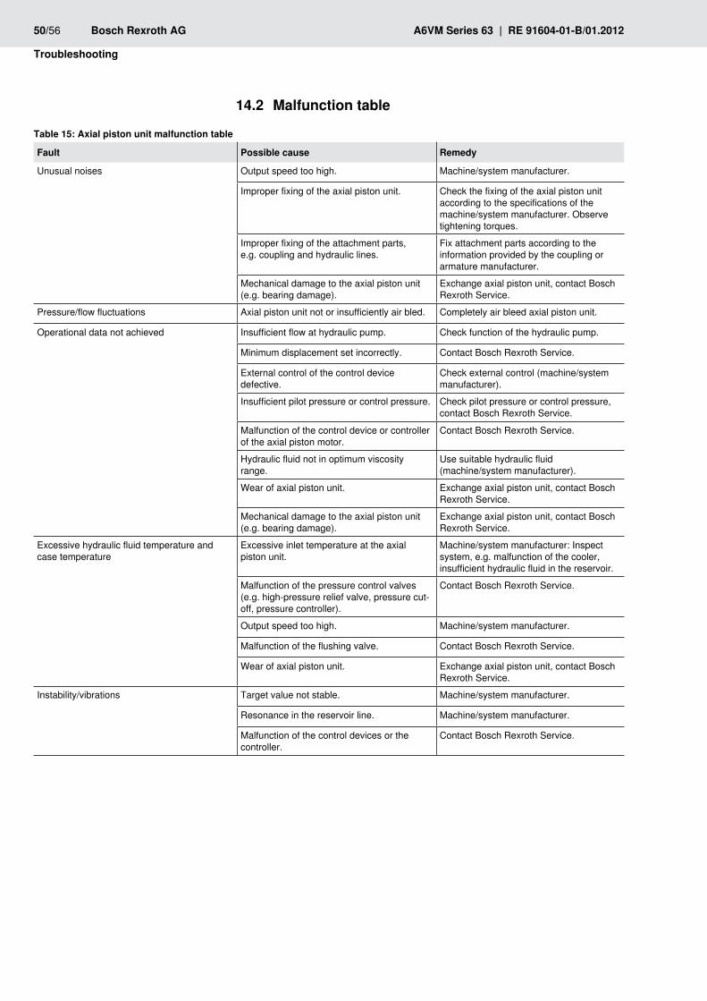
50/56 Bosch Rexroth AG A6VM Series 63 | RE 91604-01-B/01.2012
Troubleshooting
14.2 Malfunction table
Axial piston unit malfunction tableTable 15:
Fault Possible cause Remedy
Unusual noises Output speed too high. Machine/system manufacturer.
Improper fixing of the axial piston unit. Check the fixing of the axial piston unit according to the specifications of the machine/system manufacturer. Observe tightening torques.
Improper fixing of the attachment parts, e.g. coupling and hydraulic lines.
Fix attachment parts according to the information provided by the coupling or armature manufacturer.
Mechanical damage to the axial piston unit (e.g. bearing damage).
Exchange axial piston unit, contact Bosch Rexroth Service.
Pressure/flow fluctuations Axial piston unit not or insufficiently air bled. Completely air bleed axial piston unit.
Operational data not achieved Insufficient flow at hydraulic pump. Check function of the hydraulic pump.
Minimum displacement set incorrectly. Contact Bosch Rexroth Service.
External control of the control device defective.
Check external control (machine/system manufacturer).
Insufficient pilot pressure or control pressure. Check pilot pressure or control pressure, contact Bosch Rexroth Service.
Malfunction of the control device or controller of the axial piston motor.
Contact Bosch Rexroth Service.
Hydraulic fluid not in optimum viscosity range.
Use suitable hydraulic fluid (machine/system manufacturer).
Wear of axial piston unit. Exchange axial piston unit, contact Bosch Rexroth Service.
Mechanical damage to the axial piston unit (e.g. bearing damage).
Exchange axial piston unit, contact Bosch Rexroth Service.
Excessive hydraulic fluid temperature and case temperature
Excessive inlet temperature at the axial piston unit.
Machine/system manufacturer: Inspect system, e.g. malfunction of the cooler, insufficient hydraulic fluid in the reservoir.
Malfunction of the pressure control valves (e.g. high-pressure relief valve, pressure cut-off, pressure controller).
Contact Bosch Rexroth Service.
Output speed too high. Machine/system manufacturer.
Malfunction of the flushing valve. Contact Bosch Rexroth Service.
Wear of axial piston unit. Exchange axial piston unit, contact Bosch Rexroth Service.
Instability/vibrations Target value not stable. Machine/system manufacturer.
Resonance in the reservoir line. Machine/system manufacturer.
Malfunction of the control devices or the controller.
Contact Bosch Rexroth Service.
RE 91604-01-B/01.2012 | A6VM Series 63 Bosch Rexroth AG 51/56
Technical data
15 Technical dataThe permissible values of the technical data of your axial piston unit can be found in data sheet RE 91604.
The data sheets can be found on the internet atwww.boschrexroth.com/various/utilities/mediadirectory/index.jsp?&language=en-GB
Further information can be found in the online product catalog:Mobile Hydraulics: www.boschrexroth.com/axial-piston-motorsIndustrial Hydraulics: www.boschrexroth.com/ics
The order-related technical data of your axial piston unit can be found in the order confirmation.
Appendix16
16.1 Address directoryFor the addresses of foreign subsidiaries, please refer to www.boschrexroth.com/addresses
52/56 Bosch Rexroth AG A6VM Series 63 | RE 91604-01-B/01.2012
Alphabetical index
AAbbreviations 7Address directory 51Assembly 16
BBelow-reservoir installation 25
CCare 44Changing solenoid position 38Circuit
Closed 16Open 16
Cleaning 44Commissioning 39
First 39Connecting
Electrical 37Hydraulic 30
Control piston 16Conversion 48Corrosion protection 21Corrosion protection film 21Cylinder 16
DDamage to equipment 13Delivery contents 15Designations 7Dimensions 19, 27Direction of rotation 27Disposal 48Drive shaft 16
FFilling 39Flushing cycle 38Functional description
Control 17Motor function 17
Functional test 41
IIdentification 18Inspection 45Installation 23
Completing 29General instructions 27On a gearbox 29Preparation 27With coupling 28
Installation conditions 23Installation position
Below-reservoir installation 25Installing 27Instructions
General 27Intended use 8
lLens plate 16Lifting device 19Lifting strap 20
MMaintenance 44, 45Malfunction table 50
nName plate 18
OOperation 43
PPerformance description 16Piston 16Port overview 33Port plate 16Product description 16
QQualifications 9
Alphabetical index17
RE 91604-01-B/01.2012 | A6VM Series 63 Bosch Rexroth AG 53/56
Alphabetical index
RRecommissioning 42
after standstill 42Removal 47
Performing 47Preparing 47
Repair 45Replacement 47Required documentation 5Ring screw 19Running-in phase 41
SSafety instructions 8
General 9Product-specific 11Signal word 6
Spare parts 46Storage 19Storage time 21Storing 21Stroke piston 16Symbols 6
TTechnical data 51Tightening torques 36Tools 47Transport 19
With lifting strap 20With ring screw 19
Transporting 19Transport protection 30Troubleshooting 49
UUnpacking 23
wWarranty 21, 40, 48Warranty rights 30Weights 19

54/56 Bosch Rexroth AG A6VM Series 63 | RE 91604-01-B/01.2012

RE 91604-01-B/01.2012 | A6VM Series 63 Bosch Rexroth AG 55/56
Bosch Rexroth AG Axial piston unitsGlockeraustraße 489275 ElchingenGermanyTel. +49-7308-82-0Fax +49-7308-72 [email protected]/axial-piston-motors
Subject to changePrinted in GermanyRE 91604-01-B/01.2012
Bosch Rexroth AGAxial piston unitsAn den Kelterwiesen 1472160 Horb a.N.GermanyTel. +49-7451-92-0Fax [email protected]/axial-piston-motors