Embed Size (px)
Citation preview
RE 92711-01-X-B2/01.2017, Bosch Rexroth AG
Details on explosion protection ▶ Field of application according to ATEX 2014/34/EU ▶ Gas: II 3G ck IIC Tx in accordance with
DIN EN 13463-1:2009, DIN EN 13463-5:2011, DIN EN 13463-8:2003
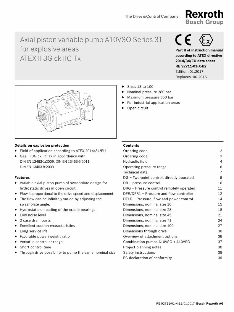
Features ▶ Variable axial piston pump of swashplate design for
hydrostatic drives in open circuit. ▶ Flow is proportional to the drive speed and displacement. ▶ The flow can be infinitely varied by adjusting the
swashplate angle. ▶ Hydrostatic unloading of the cradle bearings ▶ Low noise level ▶ 2 case drain ports ▶ Excellent suction characteristics ▶ Long service life ▶ Favorable power/weight ratio ▶ Versatile controller range ▶ Short control time ▶ Through drive possibility to pump the same nominal size
▶ Sizes 18 to 100 ▶ Nominal pressure 280 bar ▶ Maximum pressure 350 bar ▶ For industrial application areas ▶ Open circuit
Axial piston variable pump A10VSO Series 31 for explosive areasATEX II 3G ck IIC Tx
ContentsOrdering code 2Ordering code 3Hydraulic fluid 4Operating pressure range 6Technical data 7DG – Two-point control, directly operated 9DR – pressure control 10DRG – Pressure control remotely operated 11DFR/DFR1 – Pressure and flow controller 12DFLR – Pressure, flow and power control 14Dimensions, nominal size 18 15Dimensions, nominal size 28 18Dimensions, nominal size 45 21Dimensions, nominal size 71 24Dimensions, nominal size 100 27Dimensions through drive 30Overview of attachment options 36Combination pumps A10VSO + A10VSO 37Project planning notes 38Safety instructions 38EC declaration of conformity 39
Part II of instruction manual according to ATEX directive 2014/34/EU data sheetRE 92711-01-X-B2Edition: 01.2017Replaces: 06.2016
Bosch Rexroth AG, RE 92711-01-X-B2/01.2017
2 A10VSO Series 31 | Axial piston variable pumpOrdering code
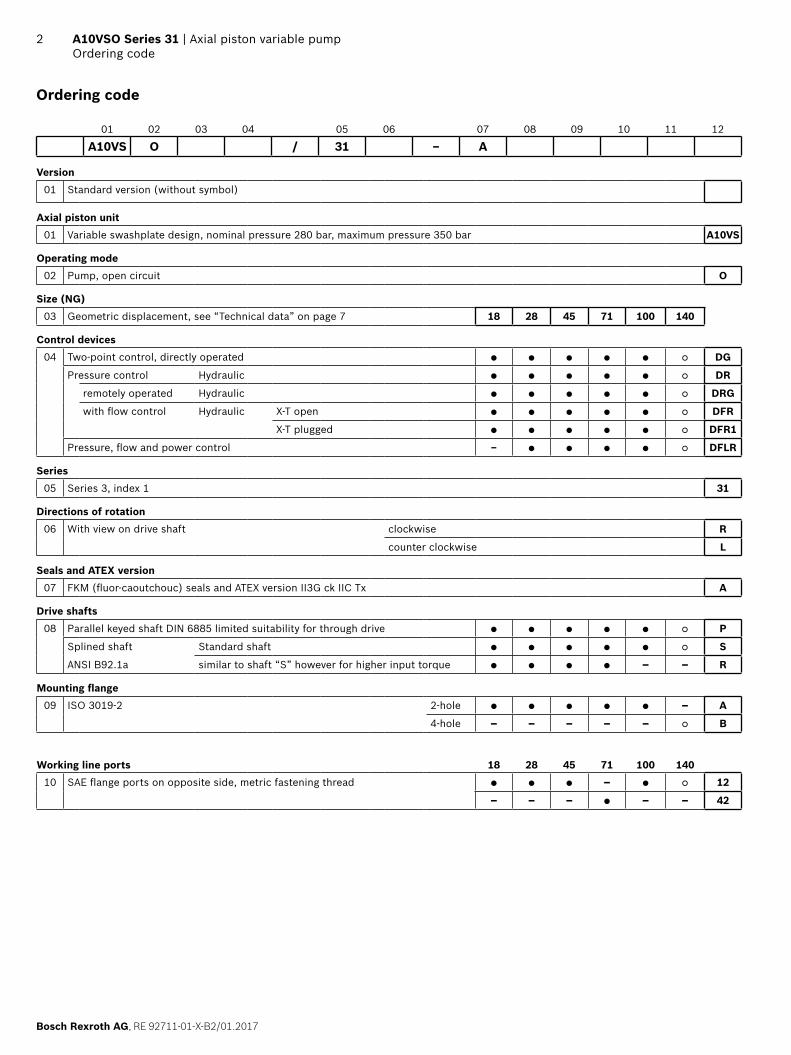
Ordering code
01 02 03 04 05 06 07 08 09 10 11 12
A10VS O / 31 – A
Version01 Standard version (without symbol)
Axial piston unit01 Variable swashplate design, nominal pressure 280 bar, maximum pressure 350 bar A10VS
Operating mode02 Pump, open circuit O
Size (NG)03 Geometric displacement, see “Technical data” on page 7 18 28 45 71 100 140
Control devices04 Two-point control, directly operated ● ● ● ● ● ○ DG
Pressure control Hydraulic ● ● ● ● ● ○ DR
remotely operated Hydraulic ● ● ● ● ● ○ DRG
with flow control Hydraulic X-T open ● ● ● ● ● ○ DFR
X-T plugged ● ● ● ● ● ○ DFR1
Pressure, flow and power control – ● ● ● ● ○ DFLR
Series05 Series 3, index 1 31
Directions of rotation06 With view on drive shaft clockwise R
counter clockwise L
Seals and ATEX version07 FKM (fluor-caoutchouc) seals and ATEX version II3G ck IIC Tx A
Drive shafts08 Parallel keyed shaft DIN 6885 limited suitability for through drive ● ● ● ● ● ○ P
Splined shaft Standard shaft ● ● ● ● ● ○ S
ANSI B92.1a similar to shaft “S” however for higher input torque ● ● ● ● – – R
Mounting flange09 ISO 3019-2 2-hole ● ● ● ● ● – A
4-hole – – – – – ○ B
Working line ports 18 28 45 71 100 14010 SAE flange ports on opposite side, metric fastening thread ● ● ● – ● ○ 12
– – – ● – – 42
RE 92711-01-X-B2/01.2017, Bosch Rexroth AG
Axial piston variable pump | A10VSO Series 31 Ordering code
3
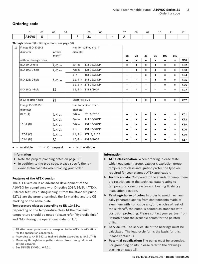
Through drives 1)(for fitting options, see page 36)
11 Flange ISO 3019-2 Hub for splined shaft2)
diameter Attach-ment3)
diameter18 28 45 71 100 140
without through drive ● ● ● ● ● ○ N00
ISO 80; 2-hole , , 3/4 in 11T 16/32DP ● ● ● ● ● ○ KB2
ISO 100; 2-hole , , 7/8 in 13T 16/32DP – ● ● ● ● ○ KB3
1 in 15T 16/32DP – – ● ● ● ○ KB4
ISO 125; 2-hole , , 1 1/4 in 14T 12/24DP – – – ● ● ○ KB5
1 1/2 in 17T 24/24DP – – – – ● ○ KB6
ISO 180; 4-hole 1 3/4 in 13T 8/16DP – – – – – ○ KB7
ø 63, metric 4-hole Shaft key ø 25 – ● ● ● ● ○ K57
Flange ISO 3019-1 Hub for splined shaft
diameter diameter
82-2 (A) , , 5/8 in 9T 16/32DP ● ● ● ● ● ○ K01
, , 3/4 in 11T 16/32DP ● ● ● ● ● ○ K52
101-2 (B) , , 7/8 in 13T 16/32DP – ● ● ● ● ○ K68
, , 1 in 15T 16/32DP – – ● ● ● ○ K04
127-2 (C) , , 1 1/2 in 17T12/24DP – – – – ● ○ K24
152-4 (D) 1 3/4 in 13T 8/16DP – – – – – ○ K17
● = Available ○ = On request – = Not available
Information ▶ Note the project planning notes on page 38! ▶ In addition to the type code, please specify the rel-
evant technical data when placing your order.
Features of the ATEX versionThe ATEX version is an advanced development of the A10VSO for compliance with Directive 2014/34/EU (ATEX). External features distinguishing it from the standard pump 92711 are the ground terminal, the Ex marking and the CE marking on the name plate.Temperature classes according to EN 13463-1Depending on the temperature class T4 the maximum temperature should be noted (please refer “Hydraulic fluid” and “Monitoring the operational data for Tx”)
Information ▶ ATEX classification: When ordering, please state
which equipment group, category, explosion group, temperature class and ignition protection type are required for your planned ATEX application.
▶ Technical data: Compared to the standard pump, there are restrictions in the technical data relating to temperature, case pressure and bearing flushing / installation position.
▶ Painting/choise of color: In order to avoid mechani-cally generated sparks from contaminants made of aluminum with iron oxide and/or particles of rust of the surface4), the pump is painted as standard with corrosion protecting. Please contact your partner from Rexroth about the available colors for the painted units.
▶ Service life: The service life of the bearings must be calculated. The load cycle forms the basis for this. Please contact us.
▶ Potential equalization: The pump must be grounded. For grounding points, please refer to the drawings starting on page 15.
Ordering code
01 02 03 04 05 06 07 08 09 10 11 12
A10VS O / 31 – A
1) All attachment pumps must correspond to the ATEX classification for the application concerned.
2) According to ANSI B92.1a (splined shafts according to SAE J744)3) Mounting through bores pattern viewed from through drive with
setting upwards4) See DIN EN 13463-1, 6.4.2.1
Bosch Rexroth AG, RE 92711-01-X-B2/01.2017
4 A10VSO Series 31 | Axial piston variable pumpHydraulic fluid
Hydraulic fluid
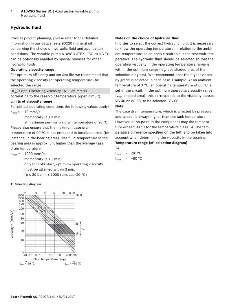
Prior to project planning, please refer to the detailed information in our data sheets 90220 (mineral oil) concerning the choice of hydraulic fluid and application conditions. The variable pump A10VSO ATEX II 3G ck IIC Tx can be optionally enabled by special releases for other hydraulic fluids.Operating viscosity rangeFor optimum efficiency and service life we recommend that the operating viscosity (at operating temperature) be selected the range nopt = opt. Operating viscosity 16 ... 36 mm2/s
correlating to the reservoir temperature (open circuit).Limits of viscosity rangeFor critical operating conditions the following values apply:nmin = 10 mm2/s momentary (t ≤ 3 min) at maximum permissible drain temperature of 90 °C.Please also ensure that the maximum case drain temperature of 90 °C is not exceeded in localized areas (for instance, in the bearing area). The fluid temperature in the bearing area is approx. 5 K higher than the average case drain temperature.nmax = 1000 mm2/s momentary (t ≤ 1 min) only for cold start, optimum operating viscosity
must be attained within 3 min. (p ≤ 30 bar, n ≤ 1000 rpm, tmin -20 °C)
▼ Selection diagram
-40
-40
-25
100
115
tmin = -20 °C tmax = +90 °C
5
10
4060
20
100
200400600
10001600
0 20 40 60 80-20
-20
νopt.
16
36
5
1600
-10 10 30 50 70800
VG 22VG 32VG 46VG 68VG 100
90
90
Visc
osity
η [
mm
2 /s]
Fluid temperature range
Notes on the choice of hydraulic fluidIn order to select the correct hydraulic fluid, it is necessary to know the operating temperature in relation to the ambi-ent temperature. In an open circuit this is the reservoir tem-perature. The hydraulic fluid should be selected so that the operating viscosity in the operating temperature range is within the optimum range (nopt see shaded area of the selection diagram). We recommend, that the higher viscos-ity grade is selected in each case. Example: At an ambient temperature of X °C, an operating temperature of 60 °C is set in the circuit. In the optimum operating viscosity range (νopt. shaded area), this corresponds to the viscosity classes VG 46 or VG 68; to be selected: VG 68.NoteThe case drain temperature, which is affected by pressure and speed, is always higher than the tank temperature. However, at no point in the component may the tempera-ture exceed 90 °C for the temperature class T4. The tem-perature difference specified on the left is to be taken into account when determining the viscosity in the bearing.Temperature range (cf. selection diagram)T4:tmin = -20 °Ctmax = +90 °C
RE 92711-01-X-B2/01.2017, Bosch Rexroth AG
Axial piston variable pump | A10VSO Series 31 Hydraulic fluid
5
Ignition temperature of hydraulic fluidThe pump is approved for temperature class T4 according to DIN EN 13463-1. According to DIN EN 13463-5 only use hydraulic fluids whose ignition temperature is at least 50 k higher than the maximum surface temperature of the approved tempera-ture class.E.g.: The reguired temperature class for the application is T4. Therefore the ignition temperature of the hydraulic fluid has to be ≥ 185 °C.Filtration of the hydraulic fluidFiner filtration improves the cleanliness level of the hydrau-lic fluid, which in turn increases the service life of the axial piston unit.A cleanliness level of at least 20/18/15 is to be maintained according to ISO 4406.Please contact us if the above classes cannot be observed.Monitoring the operational data-spezification for Tx
Safety instructionsTemperature class T4:To keep the maximum leakage temperature of 90°C at least one of the following measures must be taken and controlled regularly:
▶ check the leak oil temperature at port L or L1 (maxi-mum distance 30 cm)
▶ check the suction temperature at maximum 50°C at the suction port
▶ check the maximum suction temperature that is deter-mined at the initial operation for the following working points: – maximum working pressure and maximum flow – maximum working pressure and minimum flow
In addition to that a monitoring of the tank filling height is to be made. When the temperature limits are exceeded, suitable countermeasures have to follow.
Bosch Rexroth AG, RE 92711-01-X-B2/01.2017
6 A10VSO Series 31 | Axial piston variable pumpOperating pressure range
Operating pressure range
Pressure at working line port B Definition
Nominal pressure pnom 280 bar absolute
The nominal pressure corresponds to the maximum design pressure.
Maximum pressure pmax 350 bar absolute
The maximum pressure corresponds the maximum operating pressure within the single operating period. The sum of the single operating periods must not exceed the total operating period.Single operating period 2.5 ms
Total operating period 300 h
Minimum pressure (high pressure side)
10 bar1) absolute
Minimum pressure on the high-pressure side (B) which is required in order to prevent damage to the axial piston unit.
Rate of pressure change RA max 16000 bar/s Maximum permissible rate of pressure build-up and reduction during a pressure change over the entire pressure range.
Pressure at suction port S (Inlet)
Minimum pressure pS min
Standard 0.8 bar absolute Minimum pressure at suction port S (inlet) that is required in order to avoid damage to the axial piston unit. The minimum pressure depends on the speed and displacement of the axial piston unit.
Maximum pressure pS max 10 bar2) absolute
Case drain pressure at port L, L1
Maximum pressure pL max 2 bar absolute Maximum 0.5 bar higher than inlet pressure at port S, but not higher than pL max.A separate case drain line to the reservoir is required.
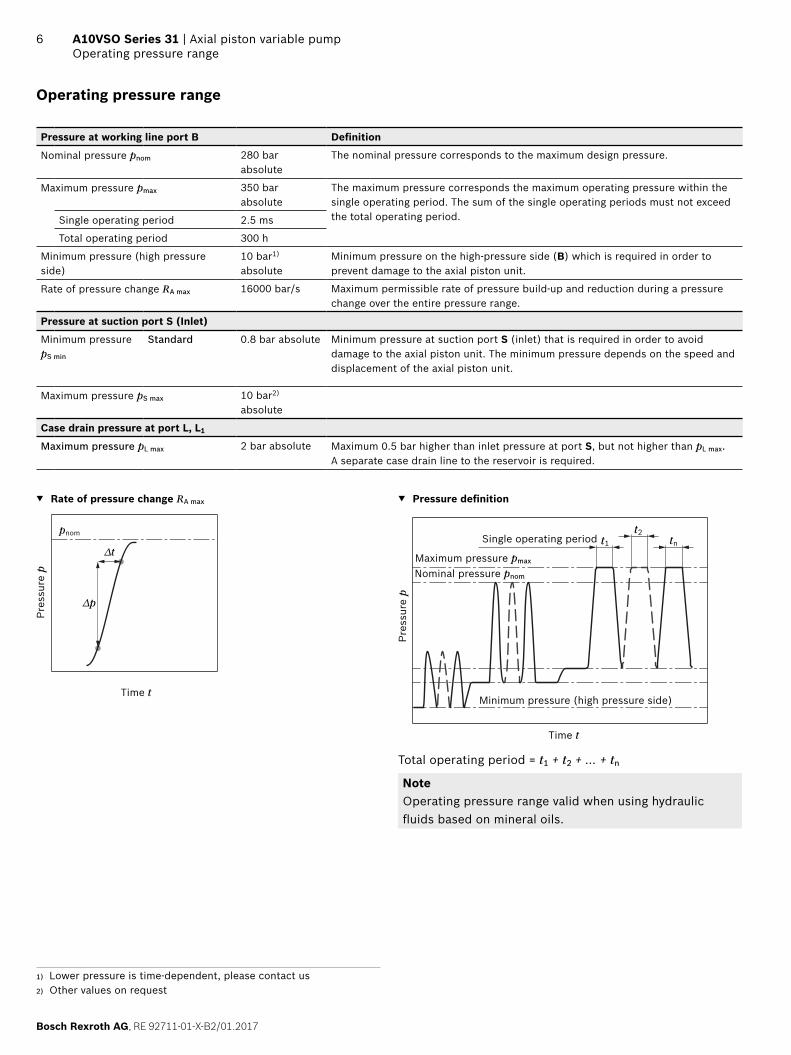
▼ Rate of pressure change RA max
pnom
∆t
∆p
Time t
Pres
sure
p
▼ Pressure definition
Pres
sure
p
t1
t2tnSingle operating period
Minimum pressure (high pressure side)
Maximum pressure pmax
Nominal pressure pnom
Time t
Total operating period = t1 + t2 + ... + tn
NoteOperating pressure range valid when using hydraulic fluids based on mineral oils.
1) Lower pressure is time-dependent, please contact us2) Other values on request
RE 92711-01-X-B2/01.2017, Bosch Rexroth AG
Axial piston variable pump | A10VSO Series 31 Technical data
7
Technical data
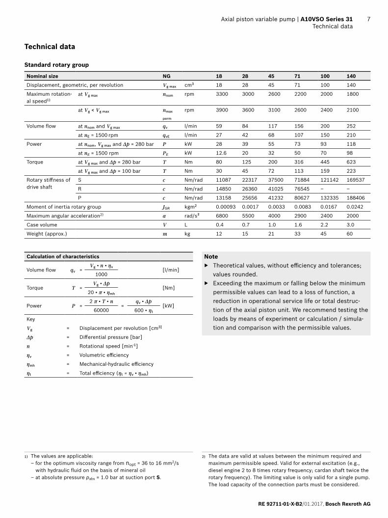
Standard rotary group
Nominal size NG 18 28 45 71 100 140
Displacement, geometric, per revolution Vg max cm3 18 28 45 71 100 140
Maximum rotation-al speed1)
at Vg max nnom rpm 3300 3000 2600 2200 2000 1800
at Vg < Vg max nmax
perm
rpm 3900 3600 3100 2600 2400 2100
Volume flow at nnom and Vg max qv l/min 59 84 117 156 200 252
at nE = 1500 rpm qvE l/min 27 42 68 107 150 210
Power at nnom, Vg max and Δp = 280 bar P kW 28 39 55 73 93 118
at nE = 1500 rpm PE kW 12.6 20 32 50 70 98
Torque at Vg max and Δp = 280 bar T Nm 80 125 200 316 445 623
at Vg max and Δp = 100 bar T Nm 30 45 72 113 159 223
Rotary stiffness of drive shaft
S c Nm/rad 11087 22317 37500 71884 121142 169537
R c Nm/rad 14850 26360 41025 76545 – –
P c Nm/rad 13158 25656 41232 80627 132335 188406
Moment of inertia rotary group JGR kgm2 0.00093 0.0017 0.0033 0.0083 0.0167 0.0242
Maximum angular acceleration2) α rad/s² 6800 5500 4000 2900 2400 2000
Case volume V L 0.4 0.7 1.0 1.6 2.2 3.0
Weight (approx.) m kg 12 15 21 33 45 60
Calculation of characteristics
Volume flow qv =Vg • n • ηv
[l/min]1000
Torque T = Vg • Δp
[Nm]20 • π • ηmh
Power P =2 π • T • n
=qv • Δp
[kW]60000 600 • ηt
Key
Vg = Displacement per revolution [cm3]
Δp = Differential pressure [bar]
n = Rotational speed [min-1]
ηv = Volumetric efficiency
ηmh = Mechanical-hydraulic efficiency
ηt = Total efficiency (ηt = ηv • ηmh)
Note ▶ Theoretical values, without efficiency and tolerances;
values rounded. ▶ Exceeding the maximum or falling below the minimum
permissible values can lead to a loss of function, a reduction in operational service life or total destruc-tion of the axial piston unit. We recommend testing the loads by means of experiment or calculation / simula-tion and comparison with the permissible values.
1) The values are applicable: – for the optimum viscosity range from nopt = 36 to 16 mm2/s with hydraulic fluid on the basis of mineral oil – at absolute pressure pabs = 1.0 bar at suction port S.
2) The data are valid at values between the minimum required and maximum permissible speed. Valid for external excitation (e.g., diesel engine 2 to 8 times rotary frequency; cardan shaft twice the rotary frequency). The limiting value is only valid for a single pump. The load capacity of the connection parts must be considered.

Bosch Rexroth AG, RE 92711-01-X-B2/01.2017
8 A10VSO Series 31 | Axial piston variable pumpOperating pressure range
Permissible radial and axial forces on the drive shaft
Nominal size NS 18 28 45 71 100 140
Maximum radial force at a/2 Fq
a
a/2 a/2
Fq max N 350 1200 1500 1900 2300 2800
Maximum axial force± Fax
+/- Fax max N 700 1000 1500 2400 4000 4800
Note ▶ For drives with radial loading (pinion, V-belt drives),
please contact us!
Permissible drive and through-drive torquesThe axial piston unit can be delivered with a through drive, as shown in the type code on page 2.The through drive version is identified by the code K01...KB06.
Permissible input and through-drive torques
Nominal size 18 28 45 71 100 140
Torque at Vg max and Δp = 280 bar1) T max Nm 80 125 200 316 445 623
Input torque at drive shaft, maximum2)
P TE max Nm 88 137 200 439 857 1206
Ø mm 18 22 25 32 40 45
S TE max Nm 124 198 319 626 1104 1620
Ø in 3/4 7/8 1 1 1/4 1 1/2 1 3/4
R TE max Nm 160 250 400 644 – –
Ø in 3/4 7/8 1 1 1/4 – –
Maximum through-drive torque
P TD max Nm 88 137 200 439 778 1206
S TD max Nm 108 160 319 492 778 1266
R TD max Nm 120 176 365 548 – –
▼ Distribution of torques
TE
TD
T1 T2
T31st Pump 2nd Pump
Torque at 1st Pump T1
Torque at 2nd Pump T2
Torque at 3rd Pump T3
Input torque TE = T1 + T2 + T3
TE < TE max
Through-drive torque TD = T2 + T3 TD < TD max
It is advisable to couple no more than three single pumps in series.For pump combinations, the maximum input torque must not be exceeded.All attachment pumps must correspond to the ATEX classifi-cation for the application concerned.
1) Efficiency not considered2) For drive shafts with no radial force
RE 92711-01-X-B2/01.2017, Bosch Rexroth AG
Axial piston variable pump | A10VSO Series 31 DG – Two-point control, directly operated
9
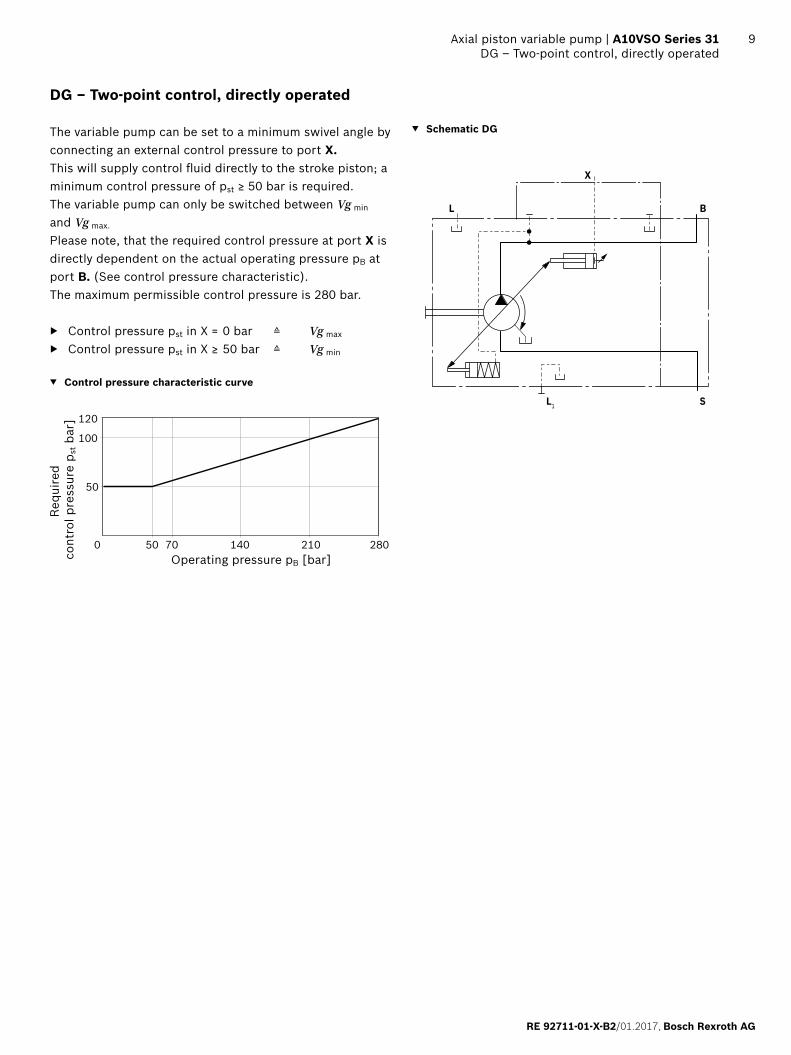
DG – Two-point control, directly operated
The variable pump can be set to a minimum swivel angle by connecting an external control pressure to port X.This will supply control fluid directly to the stroke piston; a minimum control pressure of pst ≥ 50 bar is required.The variable pump can only be switched between Vg min and Vg max.
Please note, that the required control pressure at port X is directly dependent on the actual operating pressure pB at port B. (See control pressure characteristic).The maximum permissible control pressure is 280 bar.
▶ Control pressure pst in X = 0 bar ≙ Vg max
▶ Control pressure pst in X ≥ 50 bar ≙ Vg min
▼ Control pressure characteristic curve
0 28050 70 140 210
120
100
50
Operating pressure pB [bar]
Requ
ired
con
trol
pre
ssur
e p s
t bar
]
▼ Schematic DG
SL1
B
X
L
Bosch Rexroth AG, RE 92711-01-X-B2/01.2017
10 A10VSO Series 31 | Axial piston variable pumpDR – pressure control
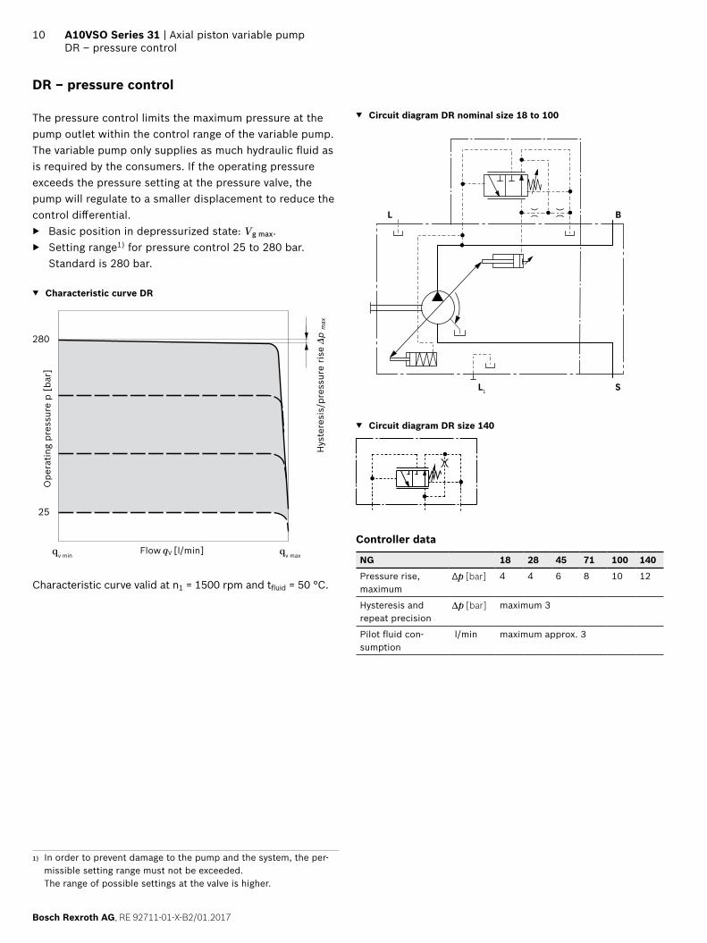
DR – pressure control
The pressure control limits the maximum pressure at the pump outlet within the control range of the variable pump. The variable pump only supplies as much hydraulic fluid as is required by the consumers. If the operating pressure exceeds the pressure setting at the pressure valve, the pump will regulate to a smaller displacement to reduce the control differential.
▶ Basic position in depressurized state: Vg max. ▶ Setting range1) for pressure control 25 to 280 bar.
Standard is 280 bar.
▼ Characteristic curve DR
280
qv min qv max
25
Ope
ratin
g pr
essu
re p
[ba
r]
Flow qV [l/min]
Hys
tere
sis/
pres
sure
ris
e Δp
max
Characteristic curve valid at n1 = 1500 rpm and tfluid = 50 °C.
▼ Circuit diagram DR nominal size 18 to 100
SL1
BL
▼ Circuit diagram DR size 140
Controller data
NG 18 28 45 71 100 140
Pressure rise, maximum
Δp [bar] 4 4 6 8 10 12
Hysteresis and repeat precision
Δp [bar] maximum 3
Pilot fluid con-sumption
l/min maximum approx. 3
1) In order to prevent damage to the pump and the system, the per-missible setting range must not be exceeded. The range of possible settings at the valve is higher.
RE 92711-01-X-B2/01.2017, Bosch Rexroth AG
Axial piston variable pump | A10VSO Series 31 DRG – Pressure controller, remotely controlled
11
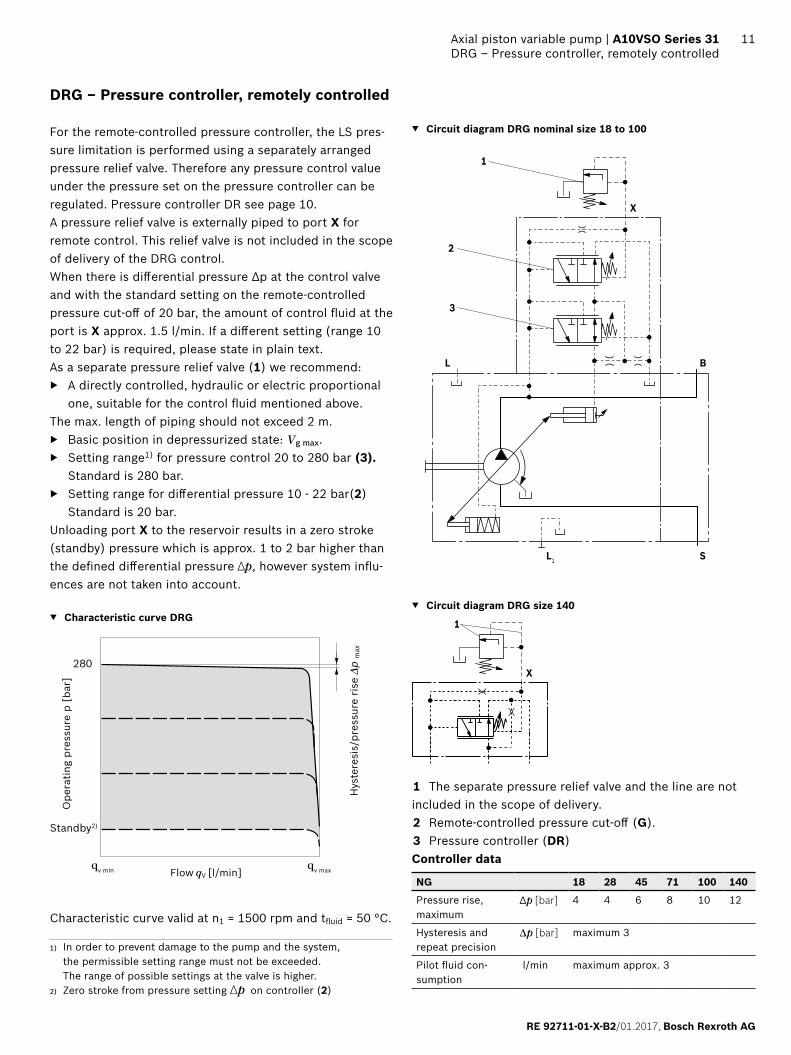
DRG – Pressure controller, remotely controlled
For the remote-controlled pressure controller, the LS pres-sure limitation is performed using a separately arranged pressure relief valve. Therefore any pressure control value under the pressure set on the pressure controller can be regulated. Pressure controller DR see page 10.A pressure relief valve is externally piped to port X for remote control. This relief valve is not included in the scope of delivery of the DRG control.When there is differential pressure Δp at the control valve and with the standard setting on the remote-controlled pressure cut-off of 20 bar, the amount of control fluid at the port is X approx. 1.5 l/min. If a different setting (range 10 to 22 bar) is required, please state in plain text.As a separate pressure relief valve (1) we recommend:
▶ A directly controlled, hydraulic or electric proportional one, suitable for the control fluid mentioned above.
The max. length of piping should not exceed 2 m. ▶ Basic position in depressurized state: Vg max. ▶ Setting range1) for pressure control 20 to 280 bar (3).
Standard is 280 bar. ▶ Setting range for differential pressure 10 - 22 bar(2)
Standard is 20 bar.Unloading port X to the reservoir results in a zero stroke (standby) pressure which is approx. 1 to 2 bar higher than the defined differential pressure ∆p, however system influ-ences are not taken into account.
▼ Characteristic curve DRG
280
qv min qv max
Standby2)
Ope
ratin
g pr
essu
re p
[ba
r]
Flow qV [l/min]
Hys
tere
sis/
pres
sure
ris
e Δp
max
Characteristic curve valid at n1 = 1500 rpm and tfluid = 50 °C.
▼ Circuit diagram DRG nominal size 18 to 100
SL1
BL
X
1
3
2
▼ Circuit diagram DRG size 140
X
1
1 The separate pressure relief valve and the line are not included in the scope of delivery.2 Remote-controlled pressure cut-off (G).3 Pressure controller (DR)Controller data
NG 18 28 45 71 100 140
Pressure rise, maximum
Δp [bar] 4 4 6 8 10 12
Hysteresis and repeat precision
Δp [bar] maximum 3
Pilot fluid con-sumption
l/min maximum approx. 3
1) In order to prevent damage to the pump and the system, the permissible setting range must not be exceeded. The range of possible settings at the valve is higher.
2) Zero stroke from pressure setting Δp on controller (2)
Bosch Rexroth AG, RE 92711-01-X-B2/01.2017
12 A10VSO Series 31 | Axial piston variable pumpDFR/DFR1 – Pressure and flow controller
1) In order to prevent damage to the pump and the system, the per-missible setting range must not be exceeded. The range of possible settings at the valve is higher.
2) Zero stroke from differential pressure setting Δp on controller (2)
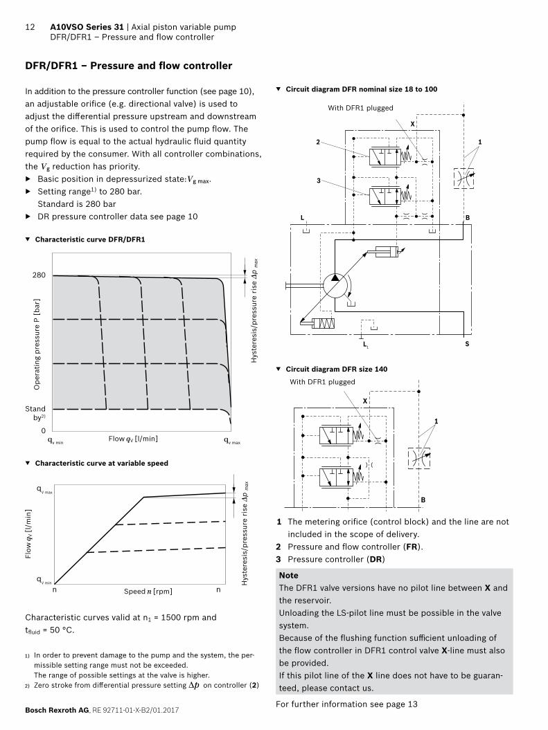
DFR/DFR1 – Pressure and flow controller
In addition to the pressure controller function (see page 10), an adjustable orifice (e.g. directional valve) is used to adjust the differential pressure upstream and downstream of the orifice. This is used to control the pump flow. The pump flow is equal to the actual hydraulic fluid quantity required by the consumer. With all controller combinations, the Vg reduction has priority.
▶ Basic position in depressurized state:Vg max. ▶ Setting range1) to 280 bar.
Standard is 280 bar ▶ DR pressure controller data see page 10
▼ Characteristic curve DFR/DFR1
280
qv min qv max
Standby2)
0
Ope
ratin
g pr
essu
re P
[ba
r]
Flow qV [l/min]
Hys
tere
sis/
pres
sure
ris
e Δp
max
▼ Characteristic curve at variable speed
qV max
qV min
n0
n maxSpeed n [rpm]
Flow
qV [
l/m
in]
Hys
tere
sis/
pres
sure
ris
e Δp
max
Characteristic curves valid at n1 = 1500 rpm and tfluid = 50 °C.
▼ Circuit diagram DFR nominal size 18 to 100
SL1
BL
X
1
3
2
With DFR1 plugged
▼ Circuit diagram DFR size 140
B
X
1
With DFR1 plugged
1 The metering orifice (control block) and the line are not included in the scope of delivery.
2 Pressure and flow controller (FR).3 Pressure controller (DR)
Note The DFR1 valve versions have no pilot line between X and the reservoir. Unloading the LS-pilot line must be possible in the valve system.Because of the flushing function sufficient unloading of the flow controller in DFR1 control valve X-line must also be provided.If this pilot line of the X line does not have to be guaran-teed, please contact us.
For further information see page 13
RE 92711-01-X-B2/01.2017, Bosch Rexroth AG
Axial piston variable pump | A10VSO Series 31 DFR/DFR1 – Pressure and flow controller
13
Differential pressure ∆p ▶ Standard setting: 14 to 22 bar.
If another setting is required, please state in clear text. Unloading port X to the reservoir results in a zero stroke (standby) pressure which is about 1 to 2 bar higher than the defined differential pressure ∆p. System influences are not taken into account.
Controller dataDR Pressure control data see page 10. Maximum flow deviation measured at drive speed n = 1500 rpm.
NG 18 28 45 71 100 140
Pressure rise, maximum
Δp [bar] 4 4 6 8 10 12
Hysteresis and repeat precision
Δp [bar] maximum 3
Pilot fluid con-sumption
l/min DFR maximum approx. 3 to 4.5DFR1 maximum approx. 3
Flow deviation ΔqV max [l/min]
0.9 1.0 1.8 2.8 4.0 6.0
Bosch Rexroth AG, RE 92711-01-X-B2/01.2017
14 A10VSO Series 31 | Axial piston variable pumpDFLR – Pressure, flow and power control
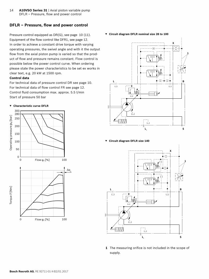
DFLR – Pressure, flow and power control
Pressure control equipped as DR(G), see page 10 (11).Equipment of the flow control like DFR1, see page 12.In order to achieve a constant drive torque with varying operating pressures, the swivel angle and with it the output flow from the axial piston pump is varied so that the prod-uct of flow and pressure remains constant. Flow control is possible below the power control curve. When ordering please state the power characteristics to be set ex works in clear text, e.g. 20 kW at 1500 rpm.Control dataFor technical data of pressure control DR see page 10.For technical data of flow control FR see page 12.Control fluid consumption max. approx. 5.5 l/minStart of pressure 50 bar
▼ Characteristic curve DFLR
0 100
0
50
100
150
200
250280300
0 100
∆qV
Flow qV [%]
Ope
ratin
g pr
essu
re p
B [b
ar]
Torq
ue T
[Nm
]
Flow qV [%]
▼ Circuit diagram DFLR nominal size 28 to 100
SL1
BL
X
1
▼ Circuit diagram DFLR size 140
SL1
BL
X
1
1 The measuring orifice is not included in the scope of supply.
RE 92711-01-X-B2/01.2017, Bosch Rexroth AG
Axial piston variable pump | A10VSO Series 31 Dimensions, nominal size 18
15Dimensions [mm]
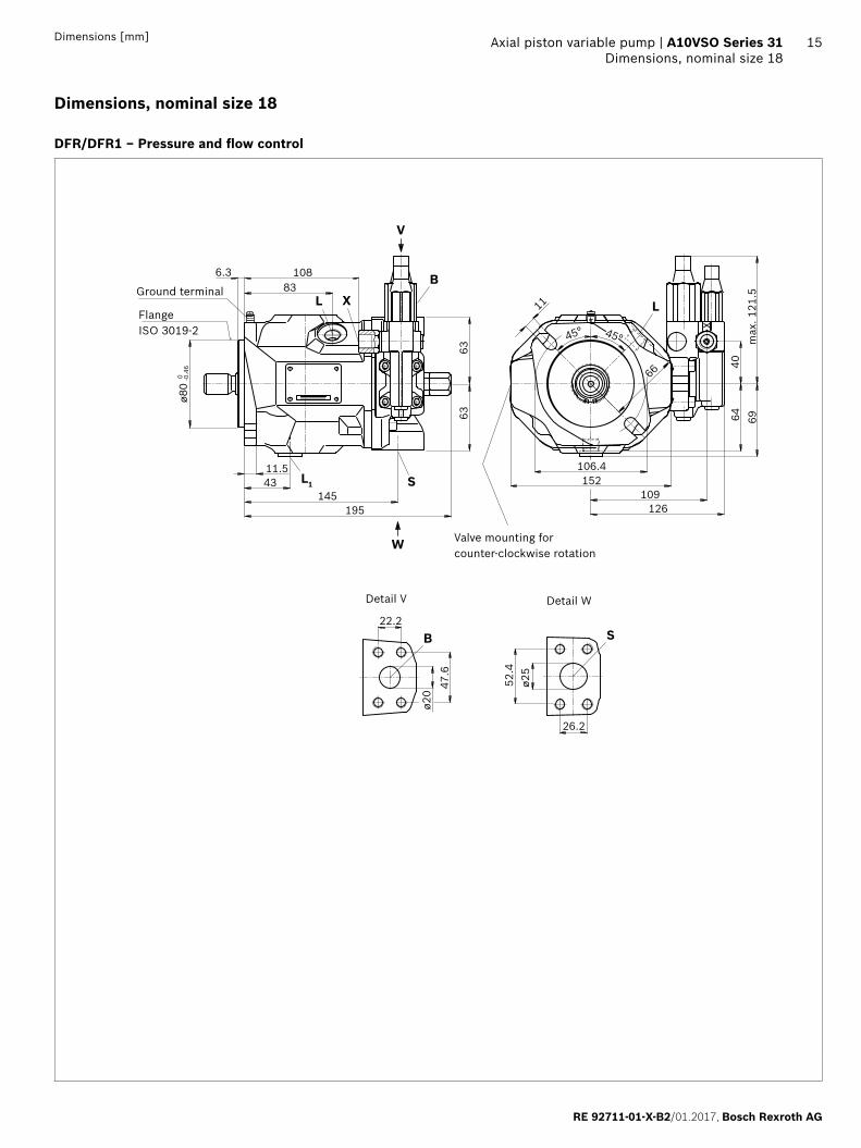
Dimensions, nominal size 18
DFR/DFR1 – Pressure and flow control
W
V
XL
L1
S
S
B
B108
ø80
-0.4
60
6.383
195
6363
1454311.5
L
66
11
45°45°
40m
ax. 1
21.5
64 69
126
152109
106.4
47.6
ø20
22.2
52.4
26.2
ø25
X
Detail V
Ground terminal
Flange ISO 3019-2
Valve mounting for counter-clockwise rotation
Detail W
Bosch Rexroth AG, RE 92711-01-X-B2/01.2017
16 A10VSO Series 31 | Axial piston variable pumpDimensions, nominal size 18
Dimensions [mm]
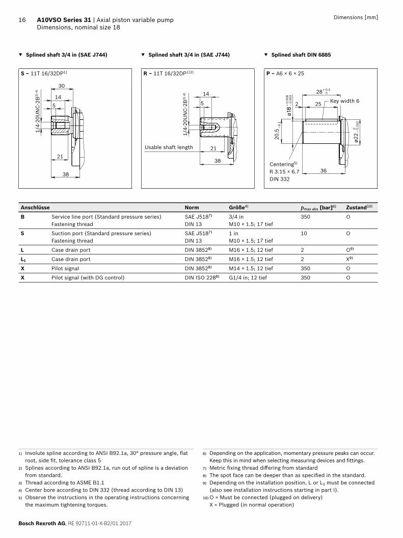
▼ Splined shaft 3/4 in (SAE J744) ▼ Splined shaft 3/4 in (SAE J744) ▼ Splined shaft DIN 6885
S ‒ 11T 16/32DP1) R ‒ 11T 16/32DP1)2) P ‒ A6 × 6 × 25
38
145
30
21
1/4-
20U
NC
-2B
3) 4
)
1/4-
20U
NC
-2B
3) 4
) 14
38
21
5
Usable shaft length
Centering5)
R 3.15 × 6.7DIN 332
36
2 25
28
20.5
–0.
1
ø22
ø18
0–
0.03
3
+ 0.30
+ 0.
008
– 0.
003
Key width 6
Anschlüsse Norm Größe4) pmax abs [bar]6) Zustand10)
B Service line port (Standard pressure series)Fastening thread
SAE J5187)
DIN 133/4 inM10 × 1.5; 17 tief
350 O
S Suction port (Standard pressure series)Fastening thread
SAE J5187)
DIN 131 inM10 × 1.5; 17 tief
10 O
L Case drain port DIN 38528) M16 × 1.5; 12 tief 2 O9)
L1 Case drain port DIN 38528) M16 × 1.5; 12 tief 2 X9)
X Pilot signal DIN 38528) M14 × 1.5; 12 tief 350 O
X Pilot signal (with DG control) DIN ISO 2288) G1/4 in; 12 tief 350 O
1) Involute spline according to ANSI B92.1a, 30° pressure angle, flat root, side fit, tolerance class 5
2) Splines according to ANSI B92.1a, run out of spline is a deviation from standard.
3) Thread according to ASME B1.14) Center bore according to DIN 332 (thread according to DIN 13)5) Observe the instructions in the operating instructions concerning
the maximum tightening torques.
6) Depending on the application, momentary pressure peaks can occur. Keep this in mind when selecting measuring devices and fittings.
7) Metric fixing thread differing from standard8) The spot face can be deeper than as specified in the standard.9) Depending on the installation position, L or L1 must be connected
(also see installation instructions starting in part I).10) O = Must be connected (plugged on delivery)
X = Plugged (in normal operation)

RE 92711-01-X-B2/01.2017, Bosch Rexroth AG
Axial piston variable pump | A10VSO Series 31 Dimensions, nominal size 18
17Dimensions [mm]
▼ DG – Zweipunktverstellung, direktgesteuert ▼ DRG – Druckregler ferngesteuert
Valve mounting for clockwise rotation
to flange surface
8997
X
148
3 G 1
/4 in
25+0
.4
12
Valve mounting for clockwise rotation
to flange surface
108
126
40
109
max
. 121
.5
X
▼ DR – Druckregler
126
max
. 121
.5
Valve mounting for clockwise rotation

Bosch Rexroth AG, RE 92711-01-X-B2/01.2017
18 A10VSO Series 31 | Axial piston variable pumpDimensions, nominal size 28
Dimensions [mm]
Dimensions, nominal size 28
DFR/DFR1 – Pressure and flow control
Detail V
Flange ISO 3019-2
Valve mounting for counter-clockwise rotation
Detail W
S
B
22.2
47.6
⌀20
30.2
58.7
⌀32
45°45°
⌀174
74
4074
14L
136119.383.5
164140
W
V
XL
L1 S
B
206
1440
164
-0.0
540
⌀10
0
6.39.5 90
118
8080
max
. 121
.5
Ground terminal
RE 92711-01-X-B2/01.2017, Bosch Rexroth AG
Axial piston variable pump | A10VSO Series 31 Dimensions, nominal size 28
19Dimensions [mm]
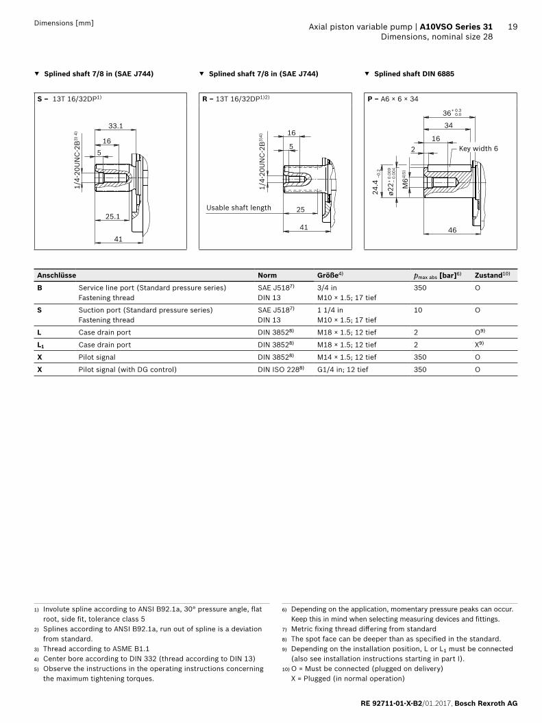
▼ Splined shaft 7/8 in (SAE J744) ▼ Splined shaft 7/8 in (SAE J744) ▼ Splined shaft DIN 6885
S ‒ 13T 16/32DP1) R ‒ 13T 16/32DP1)2) P ‒ A6 × 6 × 34
41
165
33.1
25.1
1/4-
20U
NC
-2B
3) 4
)
Usable shaft length
1/4-
20U
NC
-2B
3)4) 16
41
25
5
ø22 M
64)5)
24.4
–0.2
46
216
36+ 0.30.0
34
+ 0.
009
– 0.
004
Key width 6
Anschlüsse Norm Größe4) pmax abs [bar]6) Zustand10)
B Service line port (Standard pressure series)Fastening thread
SAE J5187)
DIN 133/4 inM10 × 1.5; 17 tief
350 O
S Suction port (Standard pressure series)Fastening thread
SAE J5187)
DIN 131 1/4 inM10 × 1.5; 17 tief
10 O
L Case drain port DIN 38528) M18 × 1.5; 12 tief 2 O9)
L1 Case drain port DIN 38528) M18 × 1.5; 12 tief 2 X9)
X Pilot signal DIN 38528) M14 × 1.5; 12 tief 350 O
X Pilot signal (with DG control) DIN ISO 2288) G1/4 in; 12 tief 350 O
1) Involute spline according to ANSI B92.1a, 30° pressure angle, flat root, side fit, tolerance class 5
2) Splines according to ANSI B92.1a, run out of spline is a deviation from standard.
3) Thread according to ASME B1.14) Center bore according to DIN 332 (thread according to DIN 13)5) Observe the instructions in the operating instructions concerning
the maximum tightening torques.
6) Depending on the application, momentary pressure peaks can occur. Keep this in mind when selecting measuring devices and fittings.
7) Metric fixing thread differing from standard8) The spot face can be deeper than as specified in the standard.9) Depending on the installation position, L or L1 must be connected
(also see installation instructions starting in part I).10) O = Must be connected (plugged on delivery)
X = Plugged (in normal operation)
Bosch Rexroth AG, RE 92711-01-X-B2/01.2017
20 A10VSO Series 31 | Axial piston variable pumpDimensions, nominal size 28
Dimensions [mm]
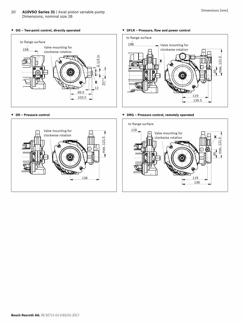
▼ DG – Two-point control, directly operated ▼ DFLR – Pressure, flow and power control
Valve mounting for clockwise rotation
to flange surface
3 G 1
/4 in
99.5103.5
12
158
25+0
.4
X
Valve mounting for clockwise rotation
to flange surface
max
. 121
.5
X
40
135.5119
198
▼ DR – Pressure control ▼ DRG – Pressure control, remotely operated
Valve mounting for clockwise rotation
max
. 121
.5
136
Valve mounting for clockwise rotation
to flange surface
max
. 121
.5X
118
136119
40

RE 92711-01-X-B2/01.2017, Bosch Rexroth AG
Axial piston variable pump | A10VSO Series 31 Dimensions, nominal size 45
21Dimensions [mm]
Dimensions, nominal size 45
DFR/DFR1 – Pressure and flow control
Detail V
Flange ISO 3019-2
Valve mounting for counter-clockwise rotation
Detail W
max
. 121
.5
SB
ø25
52.4
26.2 35.7
ø40
69.9
W
V
L X
L1
1339.5
966.3
-0.0
540
ø100
219
224
1844514.3
9090
40
L14
83
45°45°
80.5
129146
140184
93.5
Ground terminal

Bosch Rexroth AG, RE 92711-01-X-B2/01.2017
22 A10VSO Series 31 | Axial piston variable pumpDimensions, nominal size 45
Dimensions [mm]
▼ Splined shaft in (SAE J744) ▼ Splined shaft 1 in (SAE J744) ▼ Splined shaft DIN 6885
S ‒ 15T 16/32DP1) R ‒ 15T 16/32DP1)2) P ‒ A8 × 7 × 36
45.9
165
38
30
1/4-
20U
NC
-2B
3) 4
)
Usable shaft length
1/4-
20U
NC
-2B
3) 4
)
16
45.9
29.5
5 319
42+ 0.3
39
ø25 M
84)5)
28 –0
.2
52
+ 0.
009
– 0.
004
Key width 8
Anschlüsse Norm Größe4) pmax abs [bar]6) Zustand10)
B Service line port (Standard pressure series)Fastening thread
SAE J5187)
DIN 131 inM10 × 1.5; 17 tief
350 O
S Suction port (Standard pressure series)Fastening thread
SAE J5187)
DIN 131 1/2 inM12 × 1.75; 20 tief
10 O
L Case drain port DIN 38528) M22 × 1.5; 14 tief 2 O9)
L1 Case drain port DIN 38528) M14 × 1.5; 14 tief 2 X9)
X Pilot signal DIN 38528) M14 × 1.5; 12 tief 350 O
X Pilot signal (with DG control) DIN ISO 2288) G1/4 in; 12 tief 350 O
1) Involute spline according to ANSI B92.1a, 30° pressure angle, flat root, side fit, tolerance class 5
2) Splines according to ANSI B92.1a, run out of spline is a deviation from standard.
3) Thread according to ASME B1.14) Observe the instructions in the operating instructions concerning
the maximum tightening torques.5) Thread according to DIN 136) Depending on the application, momentary pressure peaks can occur.
Keep this in mind when selecting measuring devices and fittings.
7) Metric fixing thread differing from standard8) The spot face can be deeper than as specified in the standard.9) Depending on the installation position, L or L1 must be connected
(also see installation instructions starting in part I).10) O = Must be connected (plugged on delivery)
X = Plugged (in normal operation)

RE 92711-01-X-B2/01.2017, Bosch Rexroth AG
Axial piston variable pump | A10VSO Series 31 Dimensions, nominal size 45
23Dimensions [mm]
▼ DG – Two-point control, directly operated ▼ DFLR – Pressure, flow and power control
Valve mounting for clockwise rotation
to flange surface
X
G 1
/4 in
173
110117
3
12
25+0
.4
Valve mounting for clockwise rotation
to flange surface
X
max
. 121
.5
X
40
129
213
146
▼ DR –Pressure control ▼ DRG – Pressure control, remotely operated
Valve mounting for clockwise rotation
146
max
. 121
.5
Valve mounting for clockwise rotation
to flange surface
X
X
129146
133
40 max
. 121
.5
Bosch Rexroth AG, RE 92711-01-X-B2/01.2017
24 A10VSO Series 31 | Axial piston variable pumpDimensions, nominal size 71
Dimensions [mm]
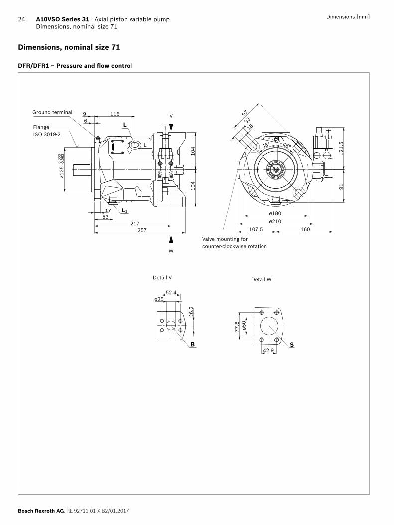
Dimensions, nominal size 71
DFR/DFR1 – Pressure and flow control
104
104
121.
5
ø25
257
97
5317
217
69 115
45°45°
18
33
ø180ø210
107.577
.8ø5
0
S42.9
B
26.2
52.4
X
160
L
L
L1
W
V
ø125
0.00
0-0
.063
91
Detail WDetail V
Ground terminal
Flange ISO 3019-2
Valve mounting for counter-clockwise rotation
RE 92711-01-X-B2/01.2017, Bosch Rexroth AG
Axial piston variable pump | A10VSO Series 31 Dimensions, nominal size 71
25Dimensions [mm]
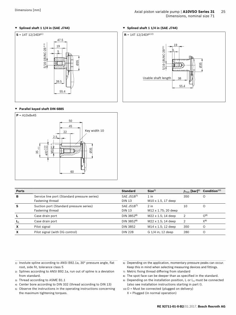
▼ Splined shaft 1 1/4 in (SAE J744) ▼ Splined shaft 1 1/4 in (SAE J744)
S ‒ 14T 12/24DP1) R ‒ 14T 12/24DP1)2)
55.4
19
5
47.5
39.5
5/16
-18U
NC-2
B 3) 5
)
Ø35
5/16
-18U
NC-2
B3)5)
19
5
55.4
38
Ø35
▼ Parallel keyed shaft DIN 6885
P ‒ A10x8x45
ø32 M10
4), 5
)
35 -0
.2
60
2.522
50
45
0.01
8 0.
002
Ø35
Ports Standard Size5) pmax [bar]6) Condition10)
B Service line port (Standard pressure series)Fastening thread
SAE J5187)
DIN 131 inM10 x 1.5, 17 deep
350 O
S Suction port (Standard pressure series)Fastening thread
SAE J5187)
DIN 132 inM12 x 1.75; 20 deep
10 O
L Case drain port DIN 38528) M22 x 1.5; 14 deep 2 O9)
L1 Case drain port DIN 38528) M22 x 1.5; 14 deep 2 X9)
X Pilot signal DIN 3852 M14 x 1.5; 12 deep 350 O
X Pilot signal (with DG control) DIN 228 G 1/4 in; 12 deep 280 O
Usable shaft length
1) Involute spline according to ANSI B92.1a, 30° pressure angle, flat root, side fit, tolerance class 5
2) Splines according to ANSI B92.1a, run out of spline is a deviation from standard.
3) Thread according to ASME B1.14) Center bore according to DIN 332 (thread according to DIN 13)5) Observe the instructions in the operating instructions concerning
the maximum tightening torques.
6) Depending on the application, momentary pressure peaks can occur. Keep this in mind when selecting measuring devices and fittings.
7) Metric fixing thread differing from standard8) The spot face can be deeper than as specified in the standard.9) Depending on the installation position, L or L1 must be connected
(also see installation instructions starting in part I).10) O = Must be connected (plugged on delivery)
X = Plugged (in normal operation)
Key width 10
Bosch Rexroth AG, RE 92711-01-X-B2/01.2017
26 A10VSO Series 31 | Axial piston variable pumpDimensions, nominal size 71
Dimensions [mm]
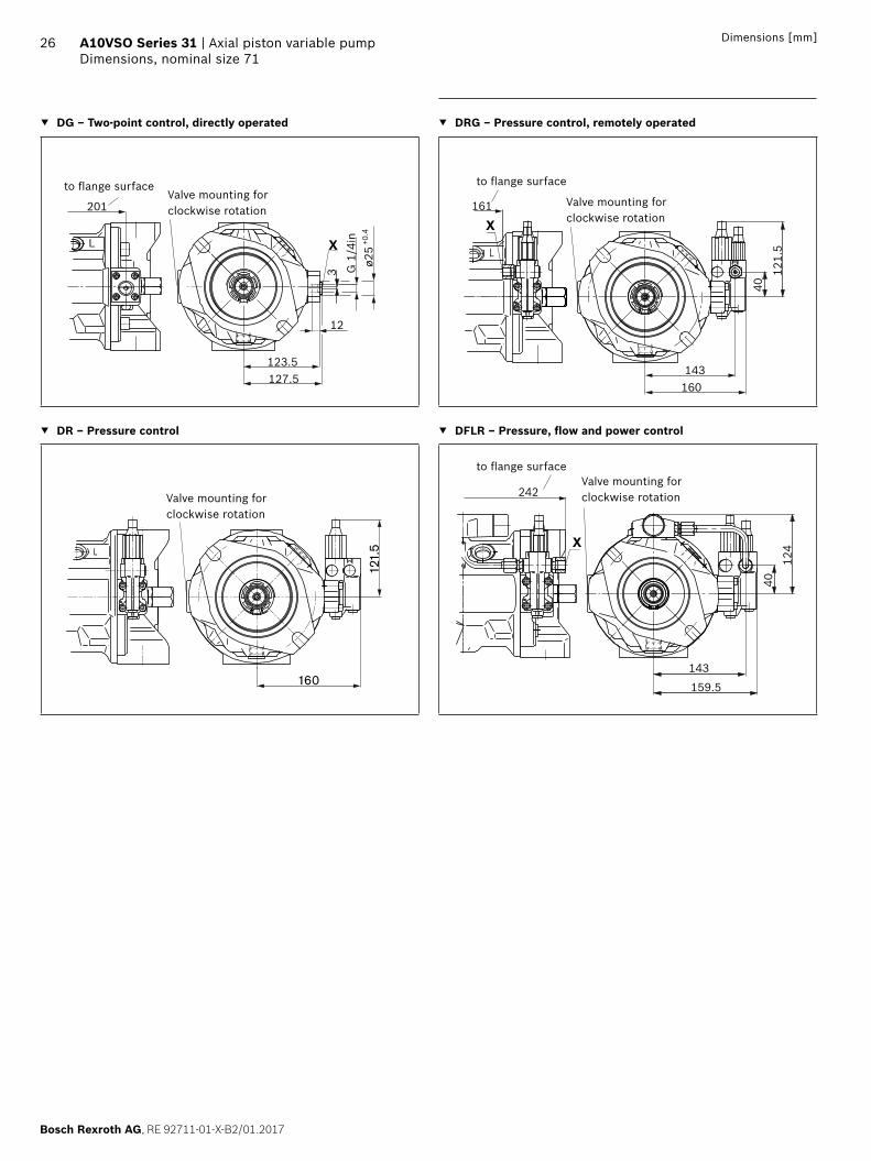
▼ DG – Two-point control, directly operated ▼ DRG – Pressure control, remotely operated
L
201
123 G
1/4
inø2
5+0
.4
127.5123.5
X L
121.
5
143160
40
161
X
X
▼ DR – Pressure control ▼ DFLR – Pressure, flow and power control
L
121.
5
160
X
40
X
242
143
159.5
124
Valve mounting for clockwise rotation
to flange surface to flange surface
to flange surface
Valve mounting for clockwise rotation
Valve mounting for clockwise rotation
Valve mounting for clockwise rotation
RE 92711-01-X-B2/01.2017, Bosch Rexroth AG
Axial piston variable pump | A10VSO Series 31 Dimensions, nominal size 100
27Dimensions [mm]
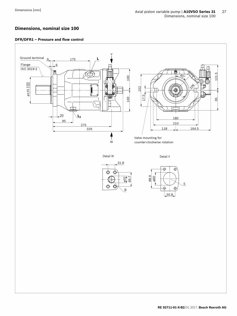
Dimensions, nominal size 100
DFR/DFR1 – Pressure and flow control
S
B
88.9
ø60
50.8
121.
595
1759
6
20
95275
L1
32910
010
0210
118
17.5
152
45°
180
106
164.5
W
V
ø125
0.0
00-0
.063
31.8
66.7
ø32
L
Detail VDetail W
Flange ISO 3019-2
Valve mounting for counter-clockwise rotation
Ground terminal
Bosch Rexroth AG, RE 92711-01-X-B2/01.2017
28 A10VSO Series 31 | Axial piston variable pumpDimensions, nominal size 100
Dimensions [mm]
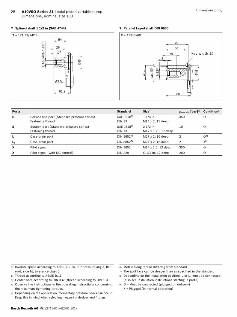
▼ Splined shaft 1 1/2 in (SAE J744) ▼ Parallel keyed shaft DIN 6885
S ‒ 17T 12/24DP1) P ‒ A12x8x68
61.9
289.5
54
43.5
7/16
-14U
NC
-2B
2)4)
Ø45
ø40 M
123)
4)
43
80
1.528
70
68
0.01
8 - 0
.002
-0.2
Ø45
Ports Standard Size4) pmax abs [bar]5) Condition9)
B Service line port (Standard pressure series)Fastening thread
SAE J5186)
DIN 131 1/4 inM14 x 2; 19 deep
350 O
S Suction port (Standard pressure series)Fastening thread
SAE J5186)
DIN 132 1/2 inM12 x 1.75; 17 deep
10 O
L Case drain port DIN 38527) M27 x 2; 16 deep 2 O8)
L1 Case drain port DIN 38527) M27 x 2; 16 deep 2 X8)
X Pilot signal DIN 3852 M14 x 1.5; 12 deep 350 O
X Pilot signal (with DG control) DIN 228 G 1/4 in; 12 deep 280 O
1) Involute spline according to ANSI B92.1a, 30° pressure angle, flat root, side fit, tolerance class 5
2) Thread according to ASME B1.13) Center bore according to DIN 332 (thread according to DIN 13)4) Observe the instructions in the operating instructions concerning
the maximum tightening torques.5) Depending on the application, momentary pressure peaks can occur.
Keep this in mind when selecting measuring devices and fittings.
6) Metric fixing thread differing from standard7) The spot face can be deeper than as specified in the standard.8) Depending on the installation position, L or L1 must be connected
(also see installation instructions starting in part I).9) O = Must be connected (plugged on delivery)
X = Plugged (in normal operation)
Key width 12

RE 92711-01-X-B2/01.2017, Bosch Rexroth AG
Axial piston variable pump | A10VSO Series 31 Dimensions, nominal size 100
29Dimensions [mm]
▼ DG – Two-point control, directly operated ▼ DFLR – Pressure, flow and power control
2681)
12
+0.4
R 1/
4in3
128.5
132.5
X
25
148
40
164.5
129
X
308
▼ DR – Pressure control ▼ DRG – Pressure controller, remotely operated
X
165
121.
5
X
40
148165
X228
121.
5
1) ER7.: 189 mm if using an intermediate plate pressure controller
Valve mounting for clockwise rotation
Valve mounting for clockwise rotation
Valve mounting for clockwise rotation
Valve mounting for clockwise rotation
to flange surface to flange surface
to flange surface
Bosch Rexroth AG, RE 92711-01-X-B2/01.2017
30 A10VSO Series 31 | Axial piston variable pumpDimensions through drive
Dimensions [mm]
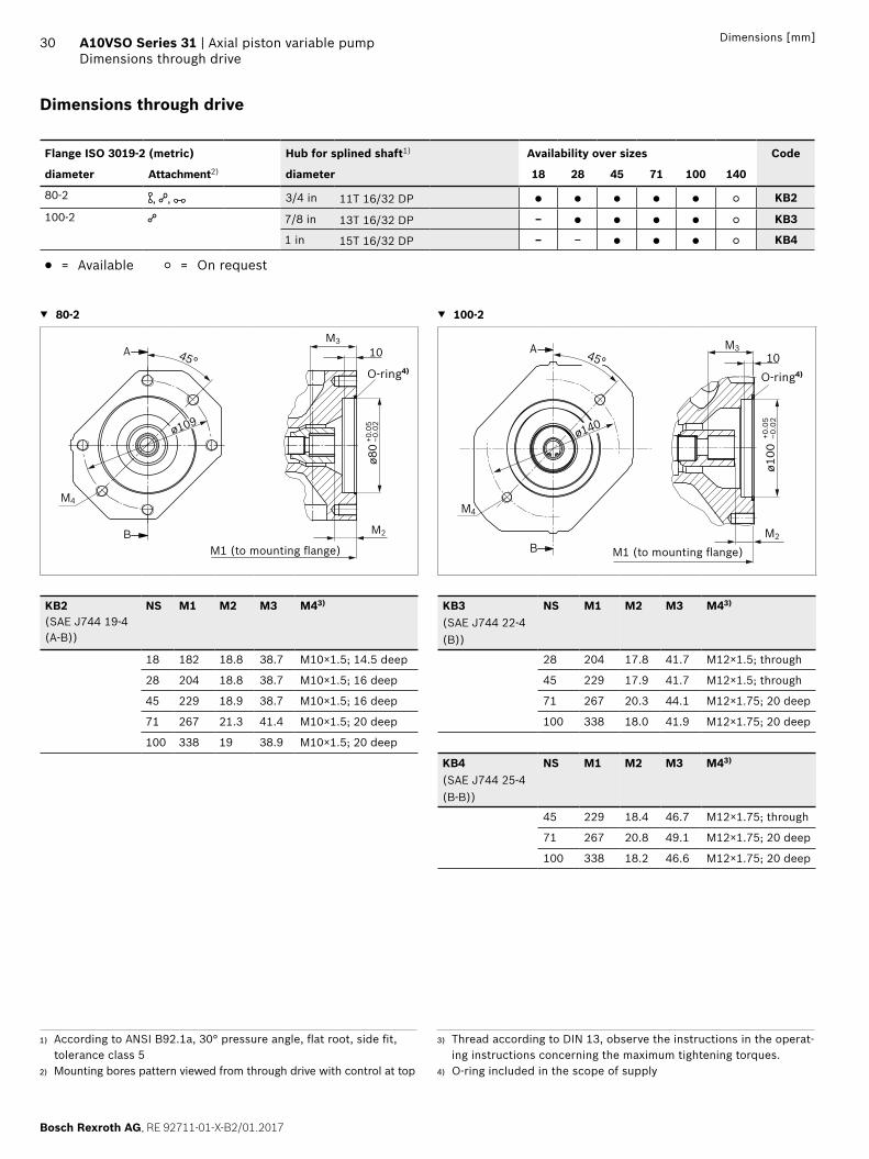
Dimensions through drive
Flange ISO 3019-2 (metric) Hub for splined shaft1) Availability over sizes Code
diameter Attachment2) diameter 18 28 45 71 100 140
80-2 , , 3/4 in 11T 16/32 DP ● ● ● ● ● ○ KB2100-2 7/8 in 13T 16/32 DP – ● ● ● ● ○ KB3
1 in 15T 16/32 DP – – ● ● ● ○ KB4
● = Available ○ = On request
▼ 80-2 ▼ 100-2
45°
M2
M4
M310
ø80
+0.0
5–0
.02
ø109
A
B
A
B
M4
45°
ø100
+0.0
5–0
.02
M2
M310
ø140
KB2 (SAE J744 19-4(A-B))
NS M1 M2 M3 M43) KB3(SAE J744 22-4(B))
NS M1 M2 M3 M43)
18 182 18.8 38.7 M10×1.5; 14.5 deep 28 204 17.8 41.7 M12×1.5; through
28 204 18.8 38.7 M10×1.5; 16 deep 45 229 17.9 41.7 M12×1.5; through
45 229 18.9 38.7 M10×1.5; 16 deep 71 267 20.3 44.1 M12×1.75; 20 deep
71 267 21.3 41.4 M10×1.5; 20 deep 100 338 18.0 41.9 M12×1.75; 20 deep
100 338 19 38.9 M10×1.5; 20 deep
KB4(SAE J744 25-4(B-B))
NS M1 M2 M3 M43)
45 229 18.4 46.7 M12×1.75; through
71 267 20.8 49.1 M12×1.75; 20 deep
100 338 18.2 46.6 M12×1.75; 20 deep
1) According to ANSI B92.1a, 30° pressure angle, flat root, side fit, tolerance class 5
2) Mounting bores pattern viewed from through drive with control at top
3) Thread according to DIN 13, observe the instructions in the operat-ing instructions concerning the maximum tightening torques.
4) O-ring included in the scope of supply
M1 (to mounting flange) M1 (to mounting flange)
O-ring4) O-ring4)
RE 92711-01-X-B2/01.2017, Bosch Rexroth AG
Axial piston variable pump | A10VSO Series 31 Dimensions through drive
31Dimensions [mm]
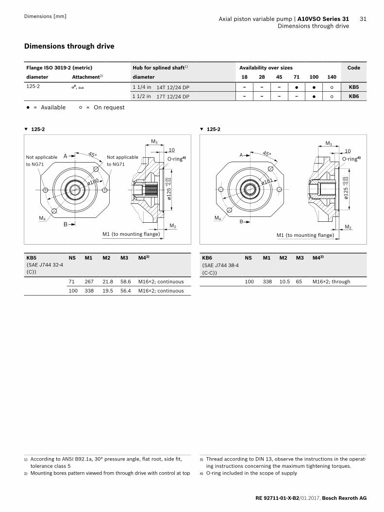
1) According to ANSI B92.1a, 30° pressure angle, flat root, side fit, tolerance class 5
2) Mounting bores pattern viewed from through drive with control at top
3) Thread according to DIN 13, observe the instructions in the operat-ing instructions concerning the maximum tightening torques.
4) O-ring included in the scope of supply
Dimensions through drive
Flange ISO 3019-2 (metric) Hub for splined shaft1) Availability over sizes Code
diameter Attachment2) diameter 18 28 45 71 100 140
125-2 , 1 1/4 in 14T 12/24 DP – – – ● ● ○ KB5
1 1/2 in 17T 12/24 DP – – – – ● ○ KB6
● = Available ○ = On request
▼ 125-2 ▼ 125-2
45°A
B
ø180
ø125
+0.0
5-0
.02
M2
M3
M4
10
ø181
45°A
BM2
M3
M4
10
ø125
+0.0
5–0
.02
KB5 (SAE J744 32-4(C))
NS M1 M2 M3 M43) KB6(SAE J744 38-4(C-C))
NS M1 M2 M3 M43)
71 267 21.8 58.6 M16×2; continuous 100 338 10.5 65 M16×2; through
100 338 19.5 56.4 M16×2; continuous
M1 (to mounting flange) M1 (to mounting flange)
Not applicable to NG71
Not applicable to NG71
O-ring4) O-ring4)
Bosch Rexroth AG, RE 92711-01-X-B2/01.2017
32 A10VSO Series 31 | Axial piston variable pumpDimensions through drive
Dimensions [mm]
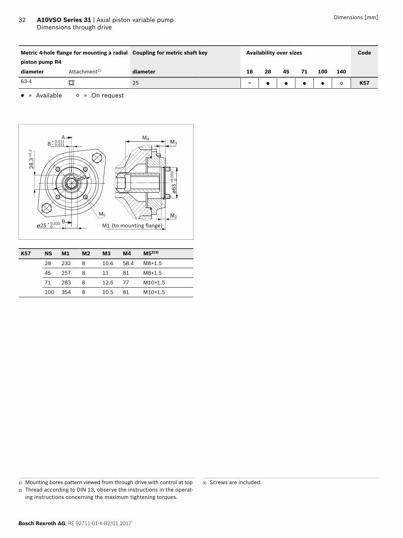
1) Mounting bores pattern viewed from through drive with control at top2) Thread according to DIN 13, observe the instructions in the operat-
ing instructions concerning the maximum tightening torques.
3) Screws are included.
M1 (to mounting flange)
Metric 4-hole flange for mounting a radial
piston pump R4
Coupling for metric shaft key Availability over sizes Code
diameter Attachment1) diameter 18 28 45 71 100 140
63-4 25 – ● ● ● ● ○ K57
● = Available ○ = On request
M2
M4 M3A
B
28.3
+0.2
ø25 + 0.0250
ø80
8 + 0.011– 0.011
M5
ø63
+0.0
320
K57 NS M1 M2 M3 M4 M52)3)
28 232 8 10.6 58.4 M8×1.5
45 257 8 11 81 M8×1.5
71 283 8 12.5 77 M10×1.5
100 354 8 10.5 81 M10×1.5
RE 92711-01-X-B2/01.2017, Bosch Rexroth AG
Axial piston variable pump | A10VSO Series 31 Dimensions through drive
33Dimensions [mm]
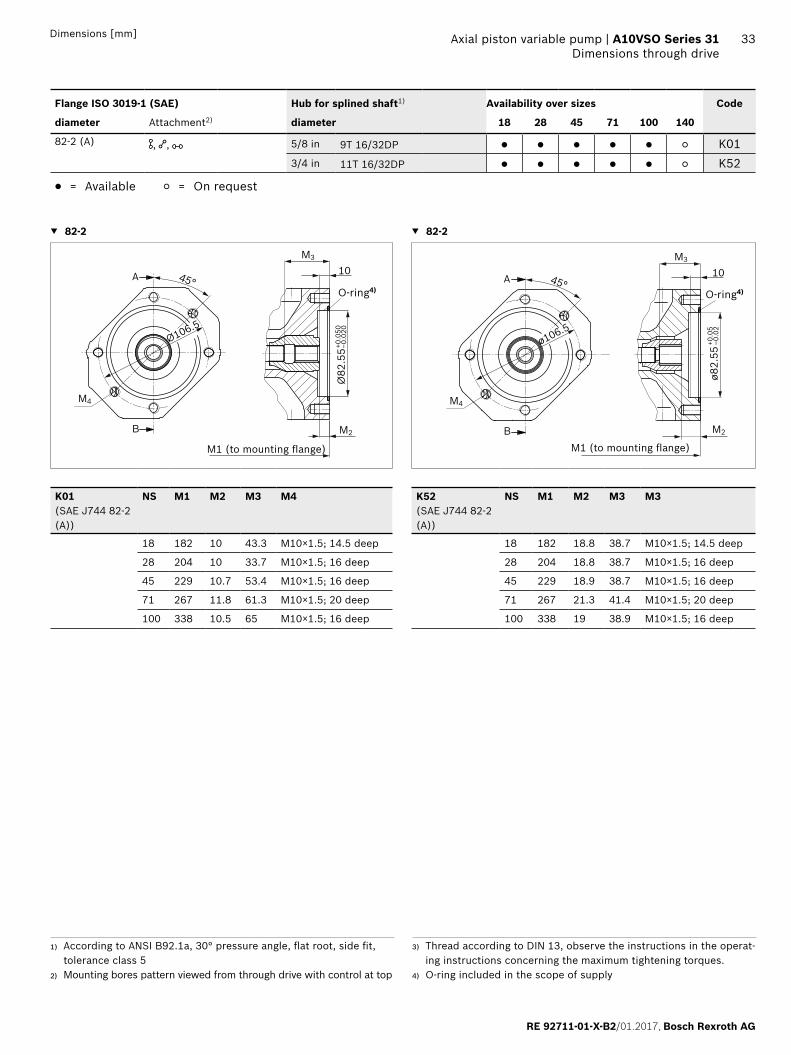
1) According to ANSI B92.1a, 30° pressure angle, flat root, side fit, tolerance class 5
2) Mounting bores pattern viewed from through drive with control at top
3) Thread according to DIN 13, observe the instructions in the operat-ing instructions concerning the maximum tightening torques.
4) O-ring included in the scope of supply
Flange ISO 3019-1 (SAE) Hub for splined shaft1) Availability over sizes Code
diameter Attachment2) diameter 18 28 45 71 100 140
82-2 (A) , , 5/8 in 9T 16/32DP ● ● ● ● ● ○ K013/4 in 11T 16/32DP ● ● ● ● ● ○ K52
● = Available ○ = On request
▼ 82-2 ▼ 82-2
Ø106.5
45°
B
A 10
Ø82
.55+0
.050
–0.0
20
M4
M3
M2
ø106.5
45°
B
A
M4
M3
M2
ø82.
55+0
.05
–0.0
2
10
K01(SAE J744 82-2(A))
NS M1 M2 M3 M4 K52(SAE J744 82-2(A))
NS M1 M2 M3 M3
18 182 10 43.3 M10×1.5; 14.5 deep 18 182 18.8 38.7 M10×1.5; 14.5 deep
28 204 10 33.7 M10×1.5; 16 deep 28 204 18.8 38.7 M10×1.5; 16 deep
45 229 10.7 53.4 M10×1.5; 16 deep 45 229 18.9 38.7 M10×1.5; 16 deep
71 267 11.8 61.3 M10×1.5; 20 deep 71 267 21.3 41.4 M10×1.5; 20 deep
100 338 10.5 65 M10×1.5; 16 deep 100 338 19 38.9 M10×1.5; 16 deep
M1 (to mounting flange) M1 (to mounting flange)
O-ring4) O-ring4)
Bosch Rexroth AG, RE 92711-01-X-B2/01.2017
34 A10VSO Series 31 | Axial piston variable pumpDimensions through drive
Dimensions [mm]
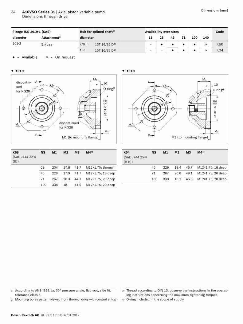
Flange ISO 3019-1 (SAE) Hub for splined shaft1) Availability over sizes Code
diameter Attachment2) diameter 18 28 45 71 100 140
101-2 , , 7/8 in 13T 16/32 DP – ● ● ● ● ○ K681 in 15T 16/32 DP – – ● ● ● ○ K04
● = Available ○ = On request
▼ 101-2 ▼ 101-2
A
B
M4
45°
ø101
.6+0
.05
–0.0
2
M2
M3
10
ø146
A
B
M4
45°
ø101
.6+0
.05
–0.0
2
M2
M3
10
ø146
K68 (SAE J744 22-4(B))
NS M1 M2 M3 M43) K04(SAE J744 25-4(B-B))
NS M1 M2 M3 M43)
28 204 17.8 41.7 M12×1.75; through 45 229 18.4 46.7 M12×1.75; 18 deep
45 229 17.9 41.7 M12×1.75; 18 deep 71 267 20.8 49.1 M12×1.75; 20 deep
71 267 20.3 44.1 M12×1.75; 20 deep 100 338 18.2 46.6 M12×1.75; 20 deep
100 338 18 41.9 M12×1.75; 20 deep
1) According to ANSI B92.1a, 30° pressure angle, flat root, side fit, tolerance class 5
2) Mounting bores pattern viewed from through drive with control at top
3) Thread according to DIN 13, observe the instructions in the operat-ing instructions concerning the maximum tightening torques.
4) O-ring included in the scope of supply
M1 (to mounting flange) M1 (to mounting flange)
discontin-uedfor NG28
discontinuedfor NG28
O-ring4)O-ring4)
RE 92711-01-X-B2/01.2017, Bosch Rexroth AG
Axial piston variable pump | A10VSO Series 31 Dimensions through drive
35Dimensions [mm]
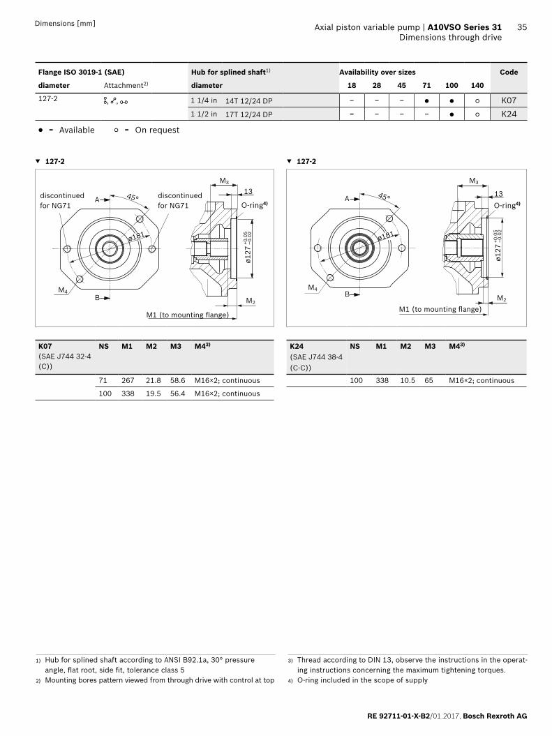
1) Hub for splined shaft according to ANSI B92.1a, 30° pressure angle, flat root, side fit, tolerance class 5
2) Mounting bores pattern viewed from through drive with control at top
3) Thread according to DIN 13, observe the instructions in the operat-ing instructions concerning the maximum tightening torques.
4) O-ring included in the scope of supply
Flange ISO 3019-1 (SAE) Hub for splined shaft1) Availability over sizes Code
diameter Attachment2) diameter 18 28 45 71 100 140
127-2 , , 1 1/4 in 14T 12/24 DP – – – ● ● ○ K071 1/2 in 17T 12/24 DP – – – – ● ○ K24
● = Available ○ = On request
▼ 127-2 ▼ 127-2
45°A
B
ø181ø1
27+0
.05
–0.0
2
M2
M3
M4
13
ø181
45°A
B M2
M3
M4
13
ø127
+0.0
5–0
.02
K07 (SAE J744 32-4(C))
NS M1 M2 M3 M43) K24(SAE J744 38-4(C-C))
NS M1 M2 M3 M43)
71 267 21.8 58.6 M16×2; continuous 100 338 10.5 65 M16×2; continuous
100 338 19.5 56.4 M16×2; continuous
M1 (to mounting flange)M1 (to mounting flange)
discontinuedfor NG71
discontinuedfor NG71 O-ring4) O-ring4)
Bosch Rexroth AG, RE 92711-01-X-B2/01.2017
36 A10VSO Series 31 | Axial piston variable pumpOverview of attachment options
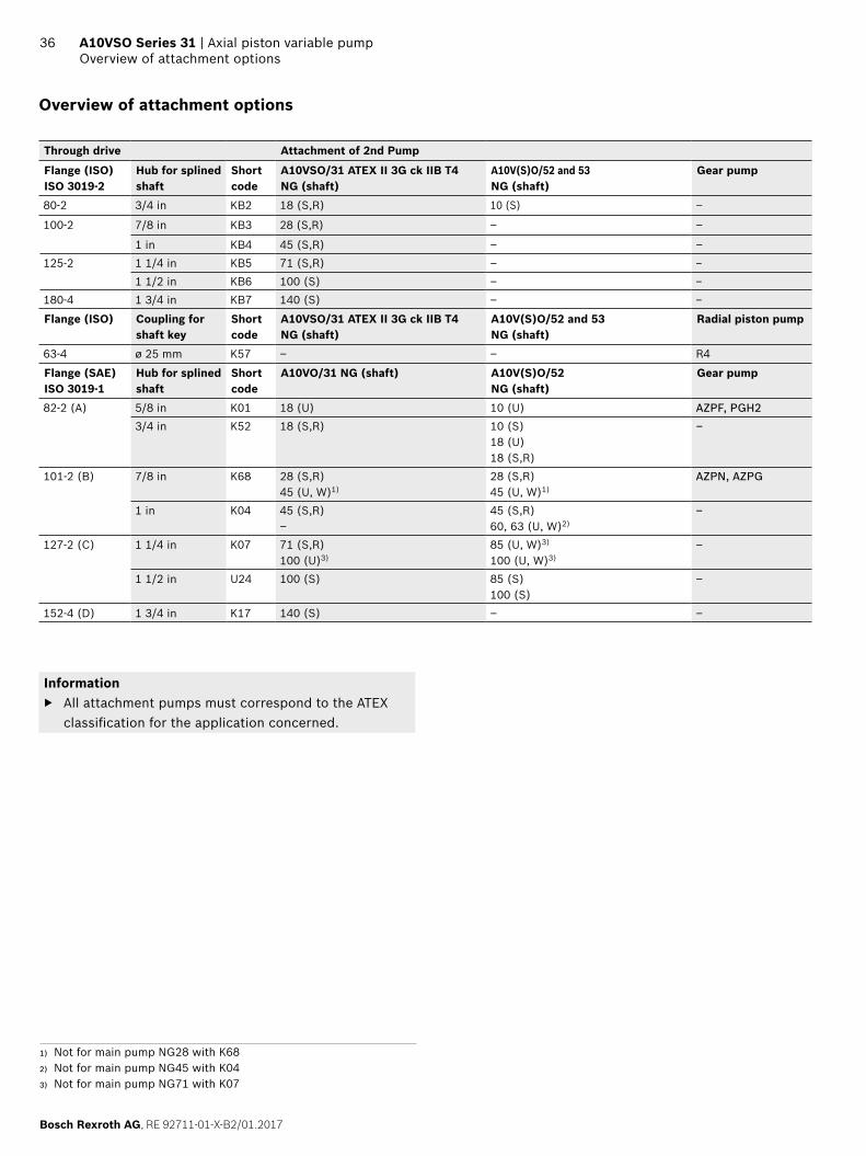
Overview of attachment options
Through drive Attachment of 2nd Pump
Flange (ISO) ISO 3019-2
Hub for splined shaft
Short code
A10VSO/31 ATEX II 3G ck IIB T4 NG (shaft)
A10V(S)O/52 and 53 NG (shaft)
Gear pump
80-2 3/4 in KB2 18 (S,R) 10 (S) –
100-2 7/8 in KB3 28 (S,R) – –
1 in KB4 45 (S,R) – –125-2 1 1/4 in KB5 71 (S,R) – –
1 1/2 in KB6 100 (S) – –180-4 1 3/4 in KB7 140 (S) – –
Flange (ISO) Coupling for shaft key
Short code
A10VSO/31 ATEX II 3G ck IIB T4 NG (shaft)
A10V(S)O/52 and 53 NG (shaft)
Radial piston pump
63-4 ø 25 mm K57 – – R4
Flange (SAE) ISO 3019-1
Hub for splined shaft
Short code
A10VO/31 NG (shaft) A10V(S)O/52 NG (shaft)
Gear pump
82-2 (A) 5/8 in K01 18 (U) 10 (U) AZPF, PGH23/4 in K52 18 (S,R) 10 (S)
18 (U)18 (S,R)
–
101-2 (B) 7/8 in K68 28 (S,R)45 (U, W)1)
28 (S,R)45 (U, W)1)
AZPN, AZPG
1 in K04 45 (S,R)–
45 (S,R)60, 63 (U, W)2)
–
127-2 (C) 1 1/4 in K07 71 (S,R)100 (U)3)
85 (U, W)3)
100 (U, W)3)–
1 1/2 in U24 100 (S) 85 (S)100 (S)
–
152-4 (D) 1 3/4 in K17 140 (S) – –
Information ▶ All attachment pumps must correspond to the ATEX
classification for the application concerned.
1) Not for main pump NG28 with K682) Not for main pump NG45 with K043) Not for main pump NG71 with K07
RE 92711-01-X-B2/01.2017, Bosch Rexroth AG
Axial piston variable pump | A10VSO Series 31 Combination pumps A10VSO + A10VSO
37Dimensions [mm]
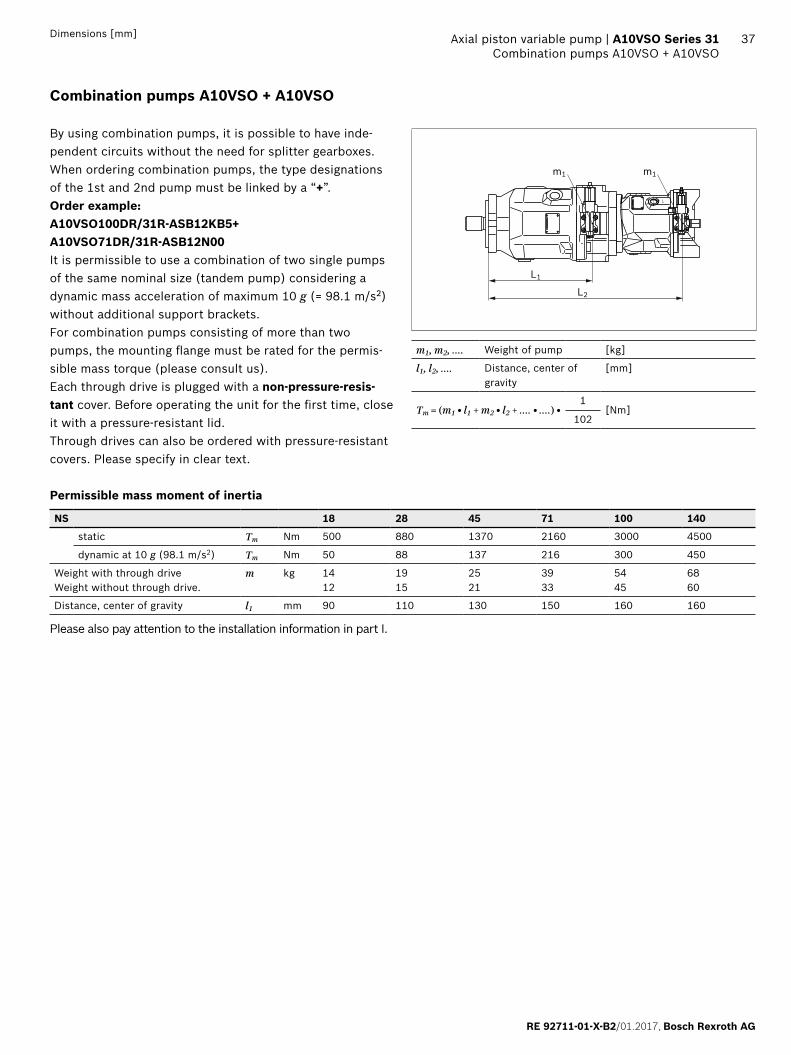
Combination pumps A10VSO + A10VSO
By using combination pumps, it is possible to have inde-pendent circuits without the need for splitter gearboxes. When ordering combination pumps, the type designations of the 1st and 2nd pump must be linked by a “+”.Order example: A10VSO100DR/31R-ASB12KB5+ A10VSO71DR/31R-ASB12N00It is permissible to use a combination of two single pumps of the same nominal size (tandem pump) considering a dynamic mass acceleration of maximum 10 g (= 98.1 m/s2) without additional support brackets. For combination pumps consisting of more than two pumps, the mounting flange must be rated for the permis-sible mass torque (please consult us).Each through drive is plugged with a non-pressure-resis-tant cover. Before operating the unit for the first time, close it with a pressure-resistant lid.Through drives can also be ordered with pressure-resistant covers. Please specify in clear text.
Permissible mass moment of inertia
NS 18 28 45 71 100 140
static Tm Nm 500 880 1370 2160 3000 4500
dynamic at 10 g (98.1 m/s2) Tm Nm 50 88 137 216 300 450
Weight with through driveWeight without through drive.
m kg 1412
1915
2521
3933
5445
6860
Distance, center of gravity l1 mm 90 110 130 150 160 160
Please also pay attention to the installation information in part I.
L
L1
m1 m1
L2
m1, m2, .... Weight of pump [kg]
l1, l2, .... Distance, center of gravity
[mm]
Tm = (m1 • l1 + m2 • l2 + .... • ....) •1
[Nm]102
Bosch Rexroth AG, RE 92711-01-X-B2/01.2017
38 A10VSO Series 31 | Axial piston variable pumpProject planning notes
Axial piston variable pump | A10VSO Series 31
Project planning notes
▶ The A10VSO ATEX II 3G ck IIC Tx pump is designed to be used in open circuits.
▶ The project planning, installation and commissioning of the axial piston unit require the involvement of qualified skilled person.
▶ Before using the axial piston unit, please read the cor-responding instruction manual completely and thor-oughly. If necessary, request these from Bosch Rexroth.
▶ Before finalizing your design, request a binding installa-tion drawing.
▶ The specified data and notes must be observed. ▶ Pressure controllers are not backups against pressure
overload. A separate pressure relief valve is to be provided in the hydraulic system.
▶ Depending on the operating condition of the axial piston unit (operating pressure, fluid temperature), the charac-teristic may shift.
▶ Not all versions of the product are approved for use in a safety function pursuant to ISO 13849. Please consult the responsible contact person at Bosch Rexroth if you require reliability parameters (e.g. MTTFd) for functional safety.
▶ Service line ports: – The ports and fixing threads are designed for the
specified peak pressure. The machine or system manu-facturer must ensure that the connecting elements and lines correspond to the specified operating conditions (pressure, flow, hydraulic fluid, temperature) with the necessary safety factors.
– The service and function ports are only designed to accommodate hydraulic lines.
Safety instructions
▶ During and shortly after operation, there is a risk of burns on the axial piston unit and especially on the solenoids. Take appropriate safety measures (e.g. by wearing protec-tive clothing).
▶ Moving parts in control equipment (e.g. valve spools) can, under certain circumstances, get blocked in position as a result of contamination (e.g. impure hydraulic fluid, abrasion, or residual dirt from components). As a result, the flow of hydraulic fluid and the build-up of momentum in the axial piston unit can no longer meet the operator's specifications. Even the use of various filter elements (external or internal flow filtering) cannot rule out errors, but can only help minimize risks. The machine/system manufacturer must check whether additional measures are required on the machine for the relevant application in order to bring the powered load into a safe position (e.g. safe stop) and ensure any measures are properly put into practice.

RE 92711-01-X-B2/01.2017, Bosch Rexroth AG
39 Axial piston variable pump | A10VSO Series 31

40
Bosch Rexroth AG, RE 92711-01-X-B2/01.2017
Bosch Rexroth AGMobile ApplicationsAn den Kelterwiesen 1472160 Horb a.N., GermanyPhone +49 7451 [email protected]
© Bosch Rexroth AG 2017. All rights reserved, also regarding any disposal, exploitation, reproduction, editing, distribution, as well as in the event of applications for industrial property rights. The data specified within only serves to describe the product. No statements concerning a certain condition or suitability for a certain application can be derived from our information. The information given does not release the user from the obligation of own judgment and verification. It must be remembered that our products are subject to a natural process of wear and aging.
A10VSO Series 31 | Axial piston variable pump