Embed Size (px)
Citation preview

AXIS M7016 Video Encoder
User Manual
About this DocumentThis manual is intended for administrators and users of theAXIS M7016 Video Encoder, and is applicable to firmware 5.90 andlater. It includes instructions for using and managing the product onyour network. Previous experience of networking will be of use whenusing this product. Some knowledge of UNIX or Linux-based systemsmay also be beneficial, for developing shell scripts and applications.Later versions of this document will be posted to the Axis website,as required. See also the product’s online help, available via theweb-based interface.
Legal ConsiderationsVideo surveillance can be regulated by laws that vary from country tocountry. Check the laws in your local region before using this productfor surveillance purposes.This product includes one (1) H.264 decoder license. To purchasefurther licenses, contact your reseller.
LiabilityEvery care has been taken in the preparation of this document. Pleaseinform your local Axis office of any inaccuracies or omissions. AxisCommunications AB cannot be held responsible for any technical ortypographical errors and reserves the right to make changes to theproduct and manuals without prior notice. Axis Communications ABmakes no warranty of any kind with regard to the material containedwithin this document, including, but not limited to, the impliedwarranties of merchantability and fitness for a particular purpose. AxisCommunications AB shall not be liable nor responsible for incidental orconsequential damages in connection with the furnishing, performanceor use of this material. This product is only to be used for its intendedpurpose.
Intellectual Property RightsAxis AB has intellectual property rights relating to technology embodiedin the product described in this document. In particular, and withoutlimitation, these intellectual property rights may include one or moreof the patents listed at www.axis.com/patent.htm and one or moreadditional patents or pending patent applications in the US and othercountries.This product contains licensed third-party software. See the menu item“About” in the product’s user interface for more information.This product contains source code copyright Apple Computer,Inc., under the terms of Apple Public Source License 2.0 (seewww.opensource.apple.com/apsl). The source code is available fromhttps://developer.apple.com/bonjour/
Equipment ModificationsThis equipment must be installed and used in strict accordance with theinstructions given in the user documentation. This equipment containsno user-serviceable components. Unauthorized equipment changes ormodifications will invalidate all applicable regulatory certificationsand approvals.
Trademark AcknowledgmentsAXIS COMMUNICATIONS, AXIS, ETRAX, ARTPEC and VAPIX areregistered trademarks or trademark applications of Axis AB in variousjurisdictions. All other company names and products are trademarks orregistered trademarks of their respective companies.Apple, Boa, Apache, Bonjour, Ethernet, Internet Explorer, Linux,Microsoft, Mozilla, Real, SMPTE, QuickTime, UNIX, Windows, WindowsVista and WWW are registered trademarks of the respective holders.Java and all Java-based trademarks and logos are trademarks orregistered trademarks of Oracle and/or its affiliates. UPnPTM is acertification mark of the UPnPTM Implementers Corporation.SD, SDHC and SDXC are trademarks or registered trademarks of SD-3C,LLC in the United States, other countries or both. Also, miniSD, microSD,miniSDHC, microSDHC, microSDXC are all trademarks or registeredtrademarks of SD-3C, LLC in the United States, other countries or both.
Regulatory InformationEurope
This product complies with the applicable CE marking directivesand harmonized standards:
• Electromagnetic Compatibility (EMC) Directive 2014/30/EU. SeeElectromagnetic Compatibility (EMC) on page 2 .
• Low Voltage (LVD) Directive 2014/35/EU. See Safety on page 2 .• Restrictions of Hazardous Substances (RoHS) Directive 2011/65/EU.
See Disposal and Recycling on page 3 .A copy of the original declaration of conformity may be obtained fromAxis Communications AB. See Contact Information on page 3 .
Electromagnetic Compatibility (EMC)This equipment has been designed and tested to fulfill applicablestandards for:• Radio frequency emission when installed according to the
instructions and used in its intended environment.• Immunity to electrical and electromagnetic phenomena when
installed according to the instructions and used in its intendedenvironment.
USAThis equipment has been tested using a shielded network cable (STP)and found to comply with the limits for a Class B digital device,pursuant to part 15 of the FCC Rules. These limits are designedto provide reasonable protection against harmful interference in aresidential installation. This equipment generates, uses and can radiateradio frequency energy and, if not installed and used in accordancewith the instructions, may cause harmful interference to radiocommunications. However, there is no guarantee that interferencewill not occur in a particular installation. If this equipment doescause harmful interference to radio or television reception, whichcan be determined by turning the equipment off and on, the user isencouraged to try to correct the interference by one or more of thefollowing measures:• Reorient or relocate the receiving antenna.• Increase the separation between the equipment and receiver.• Connect the equipment into an outlet on a circuit different from
that to which the receiver is connected.• Consult the dealer or an experienced radio/TV technician for help.The product shall be connected using a shielded network cable (STP)that is properly grounded.CanadaThis digital apparatus complies with CAN ICES-3 (Class B). The productshall be connected using a shielded network cable (STP) that isproperly grounded. Cet appareil numérique est conforme à la normeCAN NMB-3 (classe B). Le produit doit être connecté à l'aide d'un câbleréseau blindé (STP) qui est correctement mis à la terre.EuropeThis digital equipment fulfills the requirements for RF emissionaccording to the Class B limit of EN 55022. The product shall beconnected using a shielded network cable (STP) that is properlygrounded.This product fulfills the requirements for immunity accordingto EN 61000-6-1 residential, commercial and light-industrialenvironments.This product fulfills the requirements for immunity according toEN 61000-6-2 industrial environments.Australia/New ZealandThis digital equipment fulfills the requirements for RF emissionaccording to the Class B limit of AS/NZS CISPR 22. The product shallbe connected using a shielded network cable (STP) that is properlygrounded.Japanこの装置は、クラスB情報技術装置です。この装置は、家庭環境で使⽤することを⽬的としていますが、この装置がラジオやテレビジョン受信機に近接して使⽤されると、受信障害を引き起こすことがあります。取扱説明書に従って正しい取り扱いをして下さい。本製品は、シールドネットワークケーブル(STP)を使⽤して接続してください。また適切に接地してください。Korea이 기기는 가정용(B급) 전자파적합기기로서 주로 가정에서 사용하는 것을 목적으로 하며, 모든 지역에서 사용할 수있습니다. 적절히 접지된 STP (shielded twisted pair) 케이블을 사용하여 제품을 연결 하십시오.
SafetyThis product complies with IEC/EN/UL 60950-1, Safety of InformationTechnology Equipment. If its connecting cables are routed outdoors,
the product shall be grounded either through a shielded network cable(STP) or other appropriate method.The power supply used with this product shall fulfill the requirementsfor Safety Extra Low Voltage (SELV) and Limited Power Source (LPS)according to IEC/EN/UL 62368-1 orIEC/EN/UL 60950-1.
Disposal and RecyclingWhen this product has reached the end of its useful life, dispose ofit according to local laws and regulations. For information aboutyour nearest designated collection point, contact your local authorityresponsible for waste disposal. In accordance with local legislation,penalties may be applicable for incorrect disposal of this waste.Europe
This symbol means that the product shall not be disposed oftogether with household or commercial waste. Directive 2012/19/EUon waste electrical and electronic equipment (WEEE) is applicable inthe European Union member states. To prevent potential harm tohuman health and the environment, the product must be disposedof in an approved and environmentally safe recycling process. Forinformation about your nearest designated collection point, contactyour local authority responsible for waste disposal. Businesses shouldcontact the product supplier for information about how to disposeof this product correctly.This product complies with the requirements of Directive 2011/65/EU onthe restriction of the use of certain hazardous substances in electricaland electronic equipment (RoHS).China
This product complies with the requirements of the legislativeact Administration on the Control of Pollution Caused by ElectronicInformation Products (ACPEIP).
Contact InformationAxis Communications ABEmdalavägen 14223 69 LundSwedenTel: +46 46 272 18 00Fax: +46 46 13 61 30www.axis.com
SupportShould you require any technical assistance, please contact your Axisreseller. If your questions cannot be answered immediately, yourreseller will forward your queries through the appropriate channels toensure a rapid response. If you are connected to the Internet, you can:• download user documentation and software updates• find answers to resolved problems in the FAQ database. Search
by product, category, or phrase• report problems to Axis support staff by logging in to your private
support area• chat with Axis support staff• visit Axis Support at www.axis.com/techsup/
Learn More!Visit Axis learning center www.axis.com/academy/ for useful trainings,webinars, tutorials and guides.
AXIS M7016 Video Encoder
Table of Contents
Safety Information . . . . . . . . . . . . . . . . . . . . . . . . . . . . . . . . . . . . . . . . . . 6Hazard Levels . . . . . . . . . . . . . . . . . . . . . . . . . . . . . . . . . . . . . . . . . . . . . . . . . . . 6Other Message Levels . . . . . . . . . . . . . . . . . . . . . . . . . . . . . . . . . . . . . . . . . . . . 6
Hardware Overview . . . . . . . . . . . . . . . . . . . . . . . . . . . . . . . . . . . . . . . . . . 7Connectors and Buttons . . . . . . . . . . . . . . . . . . . . . . . . . . . . . . . . . . . . . . . . . . 7LED Indicators . . . . . . . . . . . . . . . . . . . . . . . . . . . . . . . . . . . . . . . . . . . . . . . . . . 8
Access the Product . . . . . . . . . . . . . . . . . . . . . . . . . . . . . . . . . . . . . . . . . . 10Access from a Browser . . . . . . . . . . . . . . . . . . . . . . . . . . . . . . . . . . . . . . . . . . . 10Access from the Internet . . . . . . . . . . . . . . . . . . . . . . . . . . . . . . . . . . . . . . . . . . 10Set the Root Password . . . . . . . . . . . . . . . . . . . . . . . . . . . . . . . . . . . . . . . . . . . 11The Live View Page . . . . . . . . . . . . . . . . . . . . . . . . . . . . . . . . . . . . . . . . . . . . . . 11
Media Streams . . . . . . . . . . . . . . . . . . . . . . . . . . . . . . . . . . . . . . . . . . . . . 14How to Stream H.264 . . . . . . . . . . . . . . . . . . . . . . . . . . . . . . . . . . . . . . . . . . . . 14MJPEG . . . . . . . . . . . . . . . . . . . . . . . . . . . . . . . . . . . . . . . . . . . . . . . . . . . . . . . . 14AXIS Media Control (AMC) . . . . . . . . . . . . . . . . . . . . . . . . . . . . . . . . . . . . . . . . 14Alternative Methods of Accessing the Video Stream . . . . . . . . . . . . . . . . . . . . 15
Set Up the Product . . . . . . . . . . . . . . . . . . . . . . . . . . . . . . . . . . . . . . . . . . 17Basic Setup . . . . . . . . . . . . . . . . . . . . . . . . . . . . . . . . . . . . . . . . . . . . . . . . . . . . 17
Video . . . . . . . . . . . . . . . . . . . . . . . . . . . . . . . . . . . . . . . . . . . . . . . . . . . . . 18Set Up Video Streams . . . . . . . . . . . . . . . . . . . . . . . . . . . . . . . . . . . . . . . . . . . . 18Quad Stream . . . . . . . . . . . . . . . . . . . . . . . . . . . . . . . . . . . . . . . . . . . . . . . . . . . 19Stream Profiles . . . . . . . . . . . . . . . . . . . . . . . . . . . . . . . . . . . . . . . . . . . . . . . . . 19ONVIF Media Profiles . . . . . . . . . . . . . . . . . . . . . . . . . . . . . . . . . . . . . . . . . . . . 20Camera Settings . . . . . . . . . . . . . . . . . . . . . . . . . . . . . . . . . . . . . . . . . . . . . . . . 20About overlay text . . . . . . . . . . . . . . . . . . . . . . . . . . . . . . . . . . . . . . . . . . . . . . . 20Privacy Mask . . . . . . . . . . . . . . . . . . . . . . . . . . . . . . . . . . . . . . . . . . . . . . . . . . . 21
Configure the Live View Page . . . . . . . . . . . . . . . . . . . . . . . . . . . . . . . . . 22PTZ (Pan Tilt Zoom) . . . . . . . . . . . . . . . . . . . . . . . . . . . . . . . . . . . . . . . . . 24Preset Positions . . . . . . . . . . . . . . . . . . . . . . . . . . . . . . . . . . . . . . . . . . . . . . . . . 24Guard Tour . . . . . . . . . . . . . . . . . . . . . . . . . . . . . . . . . . . . . . . . . . . . . . . . . . . . . 24Install PTZ Driver . . . . . . . . . . . . . . . . . . . . . . . . . . . . . . . . . . . . . . . . . . . . . . . . 24Advanced . . . . . . . . . . . . . . . . . . . . . . . . . . . . . . . . . . . . . . . . . . . . . . . . . . . . . . 25Control Queue . . . . . . . . . . . . . . . . . . . . . . . . . . . . . . . . . . . . . . . . . . . . . . . . . . 25
Detectors . . . . . . . . . . . . . . . . . . . . . . . . . . . . . . . . . . . . . . . . . . . . . . . . . . 27Camera Tampering . . . . . . . . . . . . . . . . . . . . . . . . . . . . . . . . . . . . . . . . . . . . . . 27
AXIS Video Motion Detection . . . . . . . . . . . . . . . . . . . . . . . . . . . . . . . . . 28Considerations . . . . . . . . . . . . . . . . . . . . . . . . . . . . . . . . . . . . . . . . . . . . . . . . . . 28Start and Stop the Application . . . . . . . . . . . . . . . . . . . . . . . . . . . . . . . . . . . . . 28Configure Application . . . . . . . . . . . . . . . . . . . . . . . . . . . . . . . . . . . . . . . . . . . . 28Using the Application in an Action Rule . . . . . . . . . . . . . . . . . . . . . . . . . . . . . 32
Events . . . . . . . . . . . . . . . . . . . . . . . . . . . . . . . . . . . . . . . . . . . . . . . . . . . . 33Convert Event Types to Action Rules . . . . . . . . . . . . . . . . . . . . . . . . . . . . . . . . 33Set Up Action Rules . . . . . . . . . . . . . . . . . . . . . . . . . . . . . . . . . . . . . . . . . . . . . 33Add Recipients . . . . . . . . . . . . . . . . . . . . . . . . . . . . . . . . . . . . . . . . . . . . . . . . . . 35Create Schedules . . . . . . . . . . . . . . . . . . . . . . . . . . . . . . . . . . . . . . . . . . . . . . . . 37Set Up Recurrences . . . . . . . . . . . . . . . . . . . . . . . . . . . . . . . . . . . . . . . . . . . . . . 37
Recordings . . . . . . . . . . . . . . . . . . . . . . . . . . . . . . . . . . . . . . . . . . . . . . . . . 38Find Recordings . . . . . . . . . . . . . . . . . . . . . . . . . . . . . . . . . . . . . . . . . . . . . . . . . 38Play Recording . . . . . . . . . . . . . . . . . . . . . . . . . . . . . . . . . . . . . . . . . . . . . . . . . . 38Export Video Clip . . . . . . . . . . . . . . . . . . . . . . . . . . . . . . . . . . . . . . . . . . . . . . . . 39Recording List . . . . . . . . . . . . . . . . . . . . . . . . . . . . . . . . . . . . . . . . . . . . . . . . . . 39Continuous Recording . . . . . . . . . . . . . . . . . . . . . . . . . . . . . . . . . . . . . . . . . . . . 40
Languages . . . . . . . . . . . . . . . . . . . . . . . . . . . . . . . . . . . . . . . . . . . . . . . . . 41System Options . . . . . . . . . . . . . . . . . . . . . . . . . . . . . . . . . . . . . . . . . . . . . 42Security . . . . . . . . . . . . . . . . . . . . . . . . . . . . . . . . . . . . . . . . . . . . . . . . . . . . . . . 42Date & Time . . . . . . . . . . . . . . . . . . . . . . . . . . . . . . . . . . . . . . . . . . . . . . . . . . . . 44Network . . . . . . . . . . . . . . . . . . . . . . . . . . . . . . . . . . . . . . . . . . . . . . . . . . . . . . . 45Storage . . . . . . . . . . . . . . . . . . . . . . . . . . . . . . . . . . . . . . . . . . . . . . . . . . . . . . . 50Ports & Devices . . . . . . . . . . . . . . . . . . . . . . . . . . . . . . . . . . . . . . . . . . . . . . . . . 52Maintenance . . . . . . . . . . . . . . . . . . . . . . . . . . . . . . . . . . . . . . . . . . . . . . . . . . . 53Support . . . . . . . . . . . . . . . . . . . . . . . . . . . . . . . . . . . . . . . . . . . . . . . . . . . . . . . 53
4

AXIS M7016 Video Encoder
Table of Contents
Advanced . . . . . . . . . . . . . . . . . . . . . . . . . . . . . . . . . . . . . . . . . . . . . . . . . . . . . . 54Reset to Factory Default Settings . . . . . . . . . . . . . . . . . . . . . . . . . . . . . . . . . . . 54
Troubleshooting . . . . . . . . . . . . . . . . . . . . . . . . . . . . . . . . . . . . . . . . . . . . 56Check the Firmware . . . . . . . . . . . . . . . . . . . . . . . . . . . . . . . . . . . . . . . . . . . . . 56Upgrade the Firmware . . . . . . . . . . . . . . . . . . . . . . . . . . . . . . . . . . . . . . . . . . . 56Symptoms, Possible Causes and Remedial Actions . . . . . . . . . . . . . . . . . . . . . 57
Technical Specifications . . . . . . . . . . . . . . . . . . . . . . . . . . . . . . . . . . . . . . 60Connectors . . . . . . . . . . . . . . . . . . . . . . . . . . . . . . . . . . . . . . . . . . . . . . . . . . . . 62Performance Considerations . . . . . . . . . . . . . . . . . . . . . . . . . . . . . . . . . . . . . . . 62
5
AXIS M7016 Video Encoder
Safety Information
Safety Information
Hazard LevelsDANGER
Indicates a hazardous situation which, if not avoided, will result in death or serious injury.
WARNINGIndicates a hazardous situation which, if not avoided, could result in death or serious injury.
CAUTIONIndicates a hazardous situation which, if not avoided, could result in minor or moderate injury.
NONONOTICETICETICEIndicates a situation which, if not avoided, could result in damage to property.
Other Message LevelsImportant
Indicates significant information which is essential for the product to function correctly.
NoteIndicates useful information which helps in getting the most out of the product.
6
AXIS M7016 Video Encoder
Hardware Overview
Hardware Overview
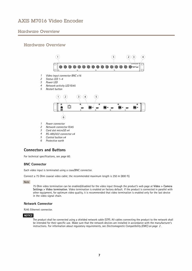
1 Video input connector BNC x162 Status LED 1–43 Power LED4 Network activity LED RJ455 Restart button
1 Power connector2 Network connector RJ453 Card slot microSD x44 RS-485/422 connector x45 Control button x46 Protective earth
Connectors and ButtonsFor technical specifications, see page 60.
BNC Connector
Each video input is terminated using a coax/BNC connector.
Connect a 75 Ohm coaxial video cable; the recommended maximum length is 250 m (800 ft).
Note75 Ohm video termination can be enabled/disabled for the video input through the product's web page at Video > CameraSettings > Video termination. Video termination is enabled on factory default. If the product is connected in parallel withother equipment, for optimum video quality, it is recommended that video termination is enabled only for the last devicein the video signal chain.
Network Connector
RJ45 Ethernet connector.
NONONOTICETICETICEThe product shall be connected using a shielded network cable (STP). All cables connecting the product to the network shallbe intended for their specific use. Make sure that the network devices are installed in accordance with the manufacturer’sinstructions. For information about regulatory requirements, see Electromagnetic Compatibility (EMC) on page 2 .
7
AXIS M7016 Video Encoder
Hardware Overview
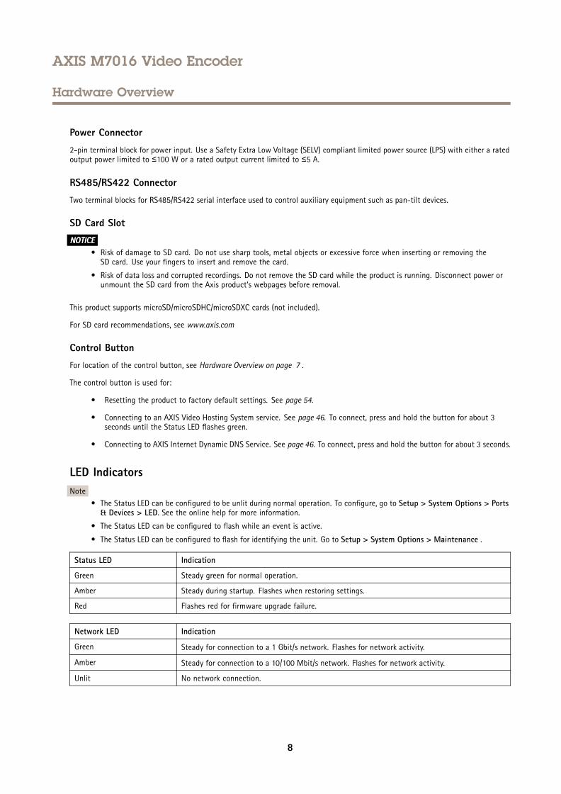
Power Connector
2-pin terminal block for power input. Use a Safety Extra Low Voltage (SELV) compliant limited power source (LPS) with either a ratedoutput power limited to ≤100 W or a rated output current limited to ≤5 A.
RS485/RS422 Connector
Two terminal blocks for RS485/RS422 serial interface used to control auxiliary equipment such as pan-tilt devices.
SD Card Slot
NONONOTICETICETICE• Risk of damage to SD card. Do not use sharp tools, metal objects or excessive force when inserting or removing theSD card. Use your fingers to insert and remove the card.
• Risk of data loss and corrupted recordings. Do not remove the SD card while the product is running. Disconnect power orunmount the SD card from the Axis product’s webpages before removal.
This product supports microSD/microSDHC/microSDXC cards (not included).
For SD card recommendations, see www.axis.com
Control Button
For location of the control button, see Hardware Overview on page 7 .
The control button is used for:
• Resetting the product to factory default settings. See page 54.
• Connecting to an AXIS Video Hosting System service. See page 46. To connect, press and hold the button for about 3seconds until the Status LED flashes green.
• Connecting to AXIS Internet Dynamic DNS Service. See page 46. To connect, press and hold the button for about 3 seconds.
LED IndicatorsNote
• The Status LED can be configured to be unlit during normal operation. To configure, go to Setup > System Options > Ports& Devices > LED. See the online help for more information.
• The Status LED can be configured to flash while an event is active.
• The Status LED can be configured to flash for identifying the unit. Go to Setup > System Options > Maintenance .
Status LED Indication
Green Steady green for normal operation.
Amber Steady during startup. Flashes when restoring settings.
Red Flashes red for firmware upgrade failure.
Network LED Indication
Green Steady for connection to a 1 Gbit/s network. Flashes for network activity.
Amber Steady for connection to a 10/100 Mbit/s network. Flashes for network activity.
Unlit No network connection.
8
AXIS M7016 Video Encoder
Hardware Overview
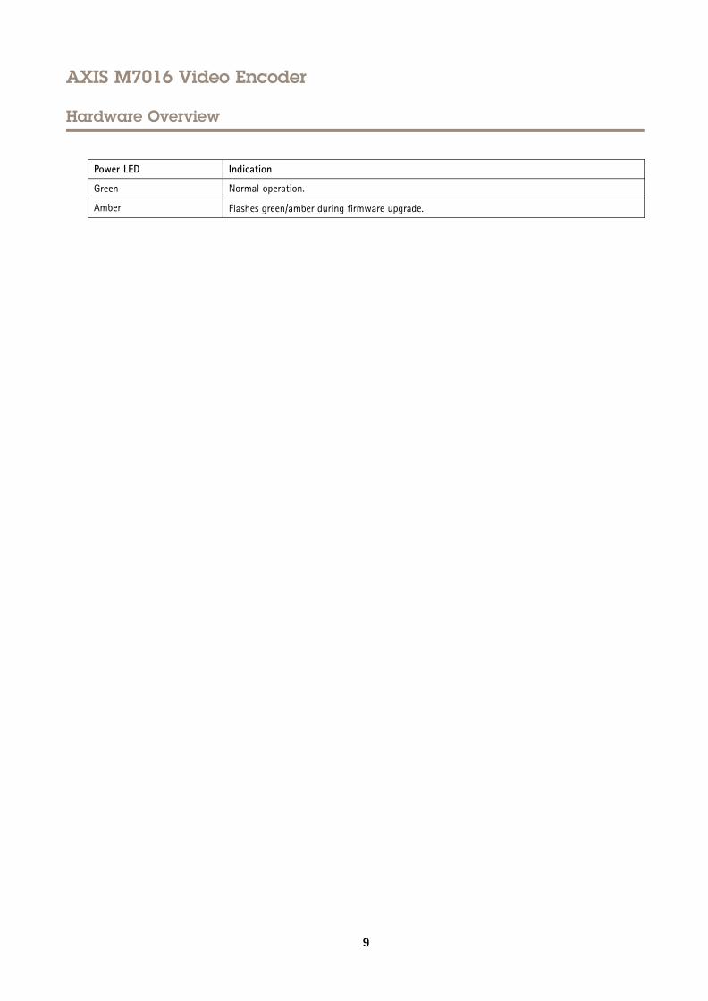
Power LED Indication
Green Normal operation.
Amber Flashes green/amber during firmware upgrade.
9
AXIS M7016 Video Encoder
Access the Product
Access the Product
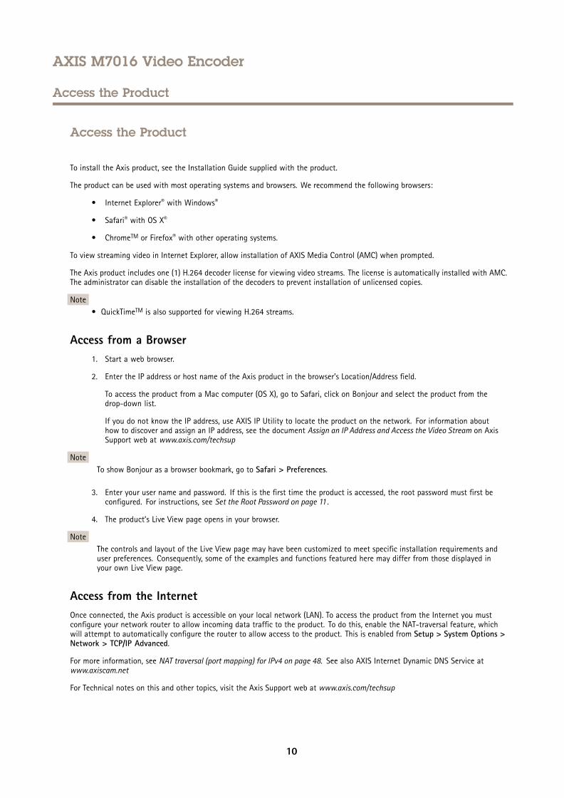
To install the Axis product, see the Installation Guide supplied with the product.
The product can be used with most operating systems and browsers. We recommend the following browsers:
• Internet Explorer® with Windows®
• Safari® with OS X®
• ChromeTM or Firefox® with other operating systems.
To view streaming video in Internet Explorer, allow installation of AXIS Media Control (AMC) when prompted.
The Axis product includes one (1) H.264 decoder license for viewing video streams. The license is automatically installed with AMC.The administrator can disable the installation of the decoders to prevent installation of unlicensed copies.
Note• QuickTimeTM is also supported for viewing H.264 streams.
Access from a Browser1. Start a web browser.
2. Enter the IP address or host name of the Axis product in the browser’s Location/Address field.
To access the product from a Mac computer (OS X), go to Safari, click on Bonjour and select the product from thedrop-down list.
If you do not know the IP address, use AXIS IP Utility to locate the product on the network. For information abouthow to discover and assign an IP address, see the document Assign an IP Address and Access the Video Stream on AxisSupport web at www.axis.com/techsup
NoteTo show Bonjour as a browser bookmark, go to Safari > Preferences.
3. Enter your user name and password. If this is the first time the product is accessed, the root password must first beconfigured. For instructions, see Set the Root Password on page 11 .
4. The product’s Live View page opens in your browser.
NoteThe controls and layout of the Live View page may have been customized to meet specific installation requirements anduser preferences. Consequently, some of the examples and functions featured here may differ from those displayed inyour own Live View page.
Access from the InternetOnce connected, the Axis product is accessible on your local network (LAN). To access the product from the Internet you mustconfigure your network router to allow incoming data traffic to the product. To do this, enable the NAT-traversal feature, whichwill attempt to automatically configure the router to allow access to the product. This is enabled from Setup > System Options >Network > TCP/IP Advanced.
For more information, see NAT traversal (port mapping) for IPv4 on page 48. See also AXIS Internet Dynamic DNS Service atwww.axiscam.net
For Technical notes on this and other topics, visit the Axis Support web at www.axis.com/techsup
10
AXIS M7016 Video Encoder
Access the Product
Set the Root PasswordTo access the Axis product, you must set the password for the default administrator user root. This is done in the Configure RootPassword dialog, which opens when the product is accessed for the first time.
To prevent network eavesdropping, the root password can be set via an encrypted HTTPS connection, which requires an HTTPScertificate. HTTPS (Hypertext Transfer Protocol over SSL) is a protocol used to encrypt traffic between web browsers and servers. TheHTTPS certificate ensures encrypted exchange of information. See HTTPS on page 43.
The default administrator user name root is permanent and cannot be deleted. If the password for root is lost, the product must bereset to the factory default settings. See Reset to Factory Default Settings on page 54.
To set the password via a standard HTTP connection, enter it directly in the dialog.
To set the password via an encrypted HTTPS connection, follow these steps:
1. Click Use HTTPS.
A temporary certificate (valid for one year) is created, enabling encryption of all traffic to and from the product, and thepassword can now be set securely.
2. Enter a password and then re-enter it to confirm the spelling.
3. Click OK. The password has now been configured.
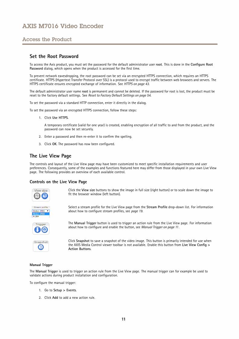
The Live View PageThe controls and layout of the Live View page may have been customized to meet specific installation requirements and userpreferences. Consequently, some of the examples and functions featured here may differ from those displayed in your own Live Viewpage. The following provides an overview of each available control.
Controls on the Live View Page
Click the View size buttons to show the image in full size (right button) or to scale down the image tofit the browser window (left button).
Select a stream profile for the Live View page from the Stream Profile drop-down list. For informationabout how to configure stream profiles, see page 19.
The Manual Trigger button is used to trigger an action rule from the Live View page. For informationabout how to configure and enable the button, see Manual Trigger on page 11 .
Click Snapshot to save a snapshot of the video image. This button is primarily intended for use whenthe AXIS Media Control viewer toolbar is not available. Enable this button from Live View Config >Action Buttons.
Manual Trigger
The Manual Trigger is used to trigger an action rule from the Live View page. The manual trigger can for example be used tovalidate actions during product installation and configuration.
To configure the manual trigger:
1. Go to Setup > Events.
2. Click Add to add a new action rule.
11
AXIS M7016 Video Encoder
Access the Product
3. From the Trigger drop-down list, select Input Signal.
4. From the second drop-down list, select Manual Trigger.
5. Select the desired action and configure the other settings as required.
For more information about action rules, see Events on page 33.
To show the manual trigger buttons in the Live View page:
1. Go to Setup > Live View Config.
2. Under Action Buttons, select Show manual trigger button.
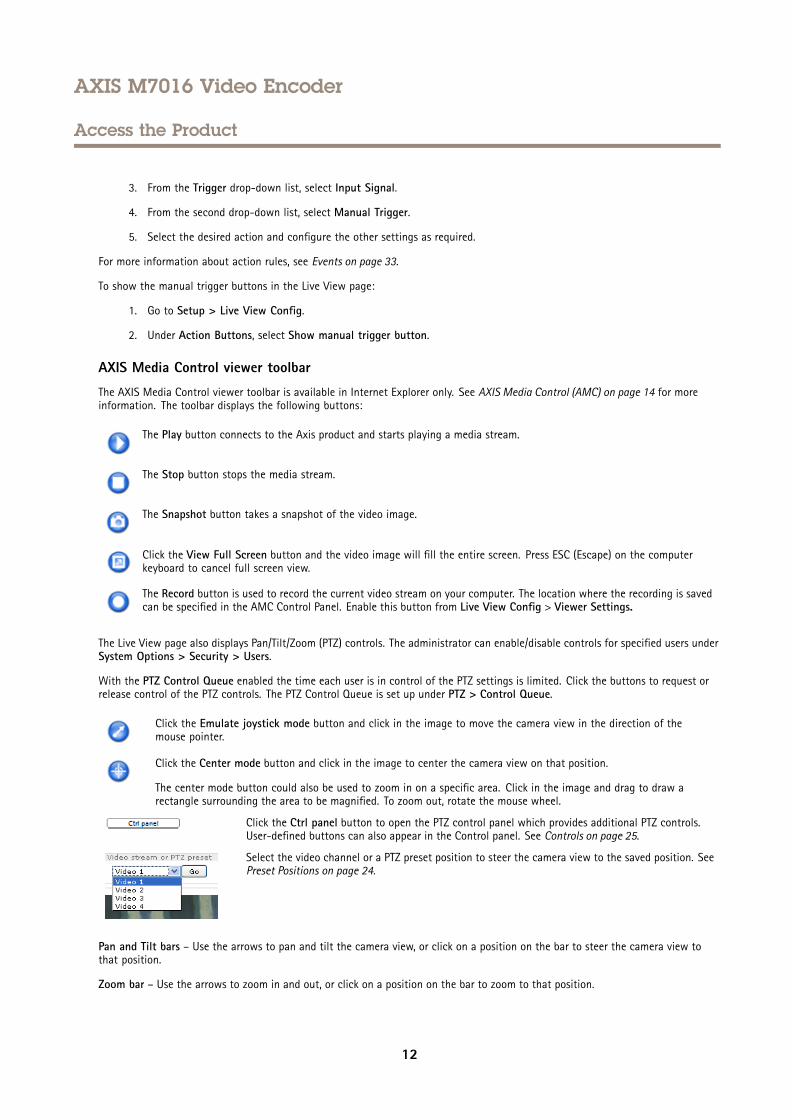
AXIS Media Control viewer toolbar
The AXIS Media Control viewer toolbar is available in Internet Explorer only. See AXIS Media Control (AMC) on page 14 for moreinformation. The toolbar displays the following buttons:
The Play button connects to the Axis product and starts playing a media stream.
The Stop button stops the media stream.
The Snapshot button takes a snapshot of the video image.
Click the View Full Screen button and the video image will fill the entire screen. Press ESC (Escape) on the computerkeyboard to cancel full screen view.
The Record button is used to record the current video stream on your computer. The location where the recording is savedcan be specified in the AMC Control Panel. Enable this button from Live View Config > Viewer Settings.
The Live View page also displays Pan/Tilt/Zoom (PTZ) controls. The administrator can enable/disable controls for specified users underSystem Options > Security > Users.
With the PTZ Control Queue enabled the time each user is in control of the PTZ settings is limited. Click the buttons to request orrelease control of the PTZ controls. The PTZ Control Queue is set up under PTZ > Control Queue.
Click the Emulate joystick mode button and click in the image to move the camera view in the direction of themouse pointer.
Click the Center mode button and click in the image to center the camera view on that position.
The center mode button could also be used to zoom in on a specific area. Click in the image and drag to draw arectangle surrounding the area to be magnified. To zoom out, rotate the mouse wheel.
Click the Ctrl panel button to open the PTZ control panel which provides additional PTZ controls.User-defined buttons can also appear in the Control panel. See Controls on page 25.
Select the video channel or a PTZ preset position to steer the camera view to the saved position. SeePreset Positions on page 24.
Pan and Tilt bars – Use the arrows to pan and tilt the camera view, or click on a position on the bar to steer the camera view tothat position.
Zoom bar – Use the arrows to zoom in and out, or click on a position on the bar to zoom to that position.
12

AXIS M7016 Video Encoder
Access the Product
Focus bar – Click on a position on the focus bar to set the focus position. This will disable the product’s autofocus. To re-enable, usethe PTZ control panel which is opened by clicking the Ctrl panel button (see above). If autofocus is enabled, Auto is visible next tothe Focus bar. For more information about the autofocus function, see Image Settings on page 20.
The PTZ controls can be disabled under PTZ > Advanced > Controls, see Controls on page 25.
13
AXIS M7016 Video Encoder
Media Streams
Media Streams
The Axis product provides several video stream formats. Your requirements and the properties of your network will determine thetype you use.
The Live View page in the product provides access to H.264 and Motion JPEG video streams, and to the list of available streamprofiles. Other applications and clients can access video streams directly, without going via the Live View page.
How to Stream H.264H.264 can, without compromising image quality, reduce the size of a digital video file by more than 80% compared with the MotionJPEG format and as much as 50% more than the MPEG-4 standard. This means that much less network bandwidth and storage spaceare required for a video file. Or seen another way, much higher video quality can be achieved for a given bit rate.
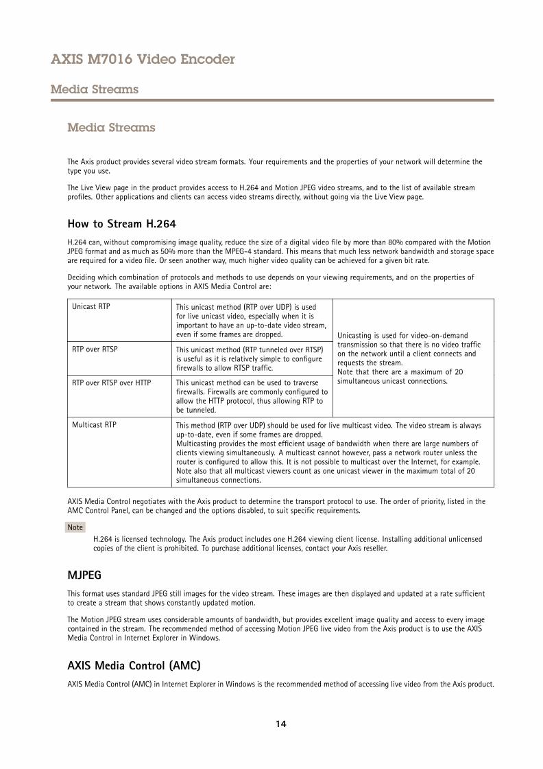
Deciding which combination of protocols and methods to use depends on your viewing requirements, and on the properties ofyour network. The available options in AXIS Media Control are:
Unicast RTP This unicast method (RTP over UDP) is usedfor live unicast video, especially when it isimportant to have an up-to-date video stream,even if some frames are dropped.
RTP over RTSP This unicast method (RTP tunneled over RTSP)is useful as it is relatively simple to configurefirewalls to allow RTSP traffic.
RTP over RTSP over HTTP This unicast method can be used to traversefirewalls. Firewalls are commonly configured toallow the HTTP protocol, thus allowing RTP tobe tunneled.
Unicasting is used for video-on-demandtransmission so that there is no video trafficon the network until a client connects andrequests the stream.Note that there are a maximum of 20simultaneous unicast connections.
Multicast RTP This method (RTP over UDP) should be used for live multicast video. The video stream is alwaysup-to-date, even if some frames are dropped.Multicasting provides the most efficient usage of bandwidth when there are large numbers ofclients viewing simultaneously. A multicast cannot however, pass a network router unless therouter is configured to allow this. It is not possible to multicast over the Internet, for example.Note also that all multicast viewers count as one unicast viewer in the maximum total of 20simultaneous connections.
AXIS Media Control negotiates with the Axis product to determine the transport protocol to use. The order of priority, listed in theAMC Control Panel, can be changed and the options disabled, to suit specific requirements.
NoteH.264 is licensed technology. The Axis product includes one H.264 viewing client license. Installing additional unlicensedcopies of the client is prohibited. To purchase additional licenses, contact your Axis reseller.
MJPEGThis format uses standard JPEG still images for the video stream. These images are then displayed and updated at a rate sufficientto create a stream that shows constantly updated motion.
The Motion JPEG stream uses considerable amounts of bandwidth, but provides excellent image quality and access to every imagecontained in the stream. The recommended method of accessing Motion JPEG live video from the Axis product is to use the AXISMedia Control in Internet Explorer in Windows.
AXIS Media Control (AMC)AXIS Media Control (AMC) in Internet Explorer in Windows is the recommended method of accessing live video from the Axis product.
14
AXIS M7016 Video Encoder
Media Streams
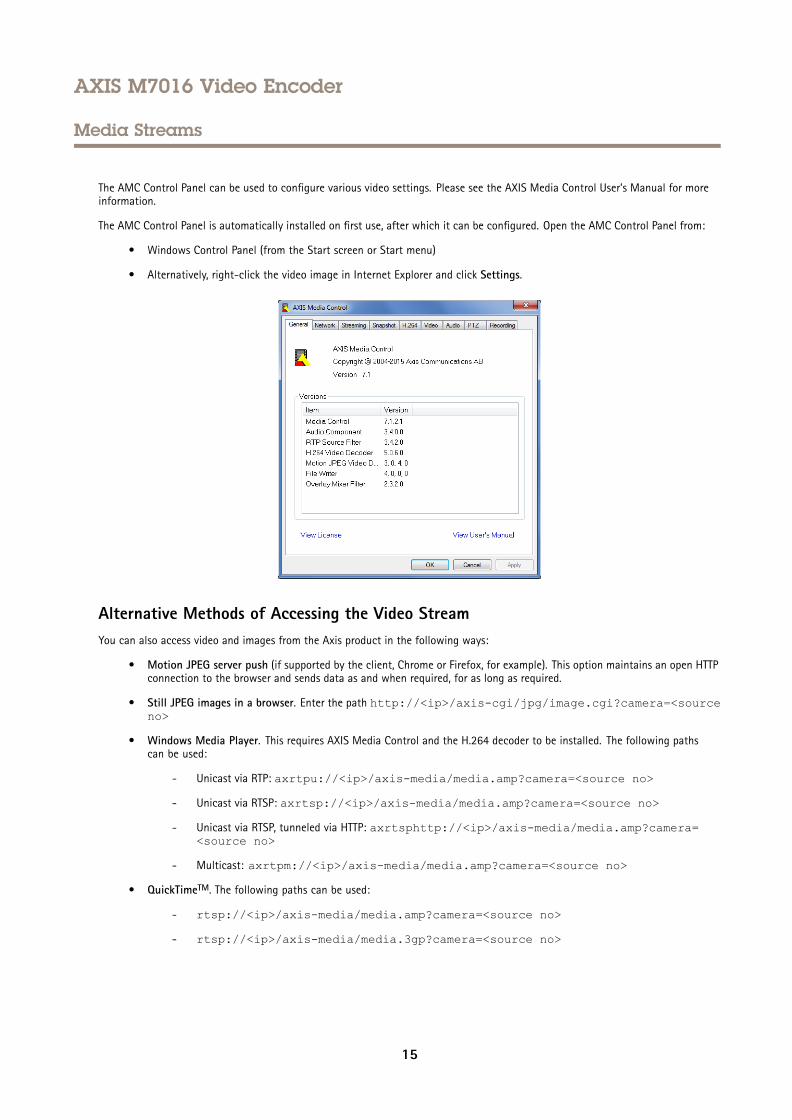
The AMC Control Panel can be used to configure various video settings. Please see the AXIS Media Control User’s Manual for moreinformation.
The AMC Control Panel is automatically installed on first use, after which it can be configured. Open the AMC Control Panel from:
• Windows Control Panel (from the Start screen or Start menu)
• Alternatively, right-click the video image in Internet Explorer and click Settings.
Alternative Methods of Accessing the Video StreamYou can also access video and images from the Axis product in the following ways:
• Motion JPEG server push (if supported by the client, Chrome or Firefox, for example). This option maintains an open HTTPconnection to the browser and sends data as and when required, for as long as required.
• Still JPEG images in a browser. Enter the path http://<ip>/axis-cgi/jpg/image.cgi?camera=<sourceno>
• Windows Media Player. This requires AXIS Media Control and the H.264 decoder to be installed. The following pathscan be used:
- Unicast via RTP: axrtpu://<ip>/axis-media/media.amp?camera=<source no>
- Unicast via RTSP: axrtsp://<ip>/axis-media/media.amp?camera=<source no>
- Unicast via RTSP, tunneled via HTTP: axrtsphttp://<ip>/axis-media/media.amp?camera=<source no>
- Multicast: axrtpm://<ip>/axis-media/media.amp?camera=<source no>
• QuickTimeTM. The following paths can be used:
- rtsp://<ip>/axis-media/media.amp?camera=<source no>
- rtsp://<ip>/axis-media/media.3gp?camera=<source no>
15

AXIS M7016 Video Encoder
Media Streams
Note• <ip>= IP address
• <source no> = 1/2/3/4/quad
• The Axis product supports QuickTime 6.5.1 and later.
• QuickTime may add latency to the video stream.
• It may be possible to use other players to view the H.264 stream using the paths above, although Axis does not guaranteethis.
16
AXIS M7016 Video Encoder
Set Up the Product
Set Up the Product
The Axis product can be configured by users with administrator or operator rights. To open the product’s Setup pages, click Setup inthe top right-hand corner of the Live View page.
• Administrators have unrestricted access to all settings.
• Operators have restricted access to settings, see Users on page 42
See also the online help .
Basic SetupBasic Setup provides shortcuts to the settings that should be made before using the Axis product:
1. Users. See page 42.
2. TCP/IP. See page 45.
3. Date & Time. See page 44.
4. Video Stream. See page 18.
The Basic Setup menu can be disabled from System Options > Security > Users.
17
AXIS M7016 Video Encoder
Video
Video
It is possible to configure the following video features in your Axis product:
• Video stream. See page 18.
• Stream profiles. See page 19.
• ONVIF Media Profiles. See page 20.
• Camera settings. See page 20.
• Overlay image. See page 20.
• Privacy mask. See page 21.
Set Up Video StreamsTo set up the product’s video streams, go to Video > Video Stream.
The video stream settings are divided into the following tabs:
• Image. See page 18.
• H.264. See page 19.
• MJPEG. See page 19.
NoteVideo stream can be configured for each channel, including quad stream.
Image
The default image settings can be configured under Video> Video Stream. Select the Image tab.
The following settings are available:
• Resolution. Select the default resolution.
• Select Aspect ratio correction to improve the appearance of images in the browser when the video stream has a differentaspect ratio. Pixels comprising the image are rearranged so as to provide a more accurate representation of the image.
• Compression. The compression level affects the image quality, bandwidth and file size of saved images; the lower thecompression, the higher the image quality with higher bandwidth requirements and larger file sizes.
• Mirror image. If required, the image can be mirrored.
• Rotate image. If required, the image can be rotated.
• Color setting. Select either Color or Black & White. Black & White uses less bandwidth than Color.
• Maximum frame rate. To avoid bandwidth problems, the frame rate allowed to each viewer can be Limited to a fixedamount. Alternatively, the frame rate can be set as Unlimited, which means the Axis product always delivers the highestframe rate possible under the current conditions.
• Overlay settings. See About overlay text on page 20.
Click Save to apply the new settings.
18
AXIS M7016 Video Encoder
Video
H.264
H.264, also known as MPEG-4 Part 10/AVC, is a video compression standard that provides high quality video streams at low bit rates.An H.264 video stream consists of different types of frames such as I-frames and P-frames. An I-frame is a complete image whereasP-frames only contain the differences from previous frames.
The H.264 stream settings can be configured from the Video > Video Stream page. Select the H.264 tab. The settings defined in thispage will apply to all H.264 streams that do not use a stream profile.
The GOP length is the number of frames between two consecutive I-frames. Increasing the GOP length may save considerably onbandwidth requirements in some cases, but may also have an adverse affect on image quality.
The Axis product supports the following H.264 profile(s):
• Baseline. The Baseline profile is recommended for clients that don’t support CABAC entropy coding.
• Main. The Main profile provides higher compression with maintained video quality compared to the Baseline profile butrequires more processing power to decode.
The bit rate can be set as Variable bit rate (VBR) or Maximum bit rate (MBR). VBR adjusts the bit rate according to the imagecomplexity, using up more bandwidth for increased activity in the image, and less for lower image activity. When the activity inthe scene increases, the bit rate would usually increase as well. If there is a surplus in bandwidth, this may not be an issue andselecting Variable bit rate (VBR) will be sufficient. But if bandwidth is limited, it is recommended to control the bit rate by selectingMaximum bit rate (MBR). When the activity in the scene increases, VBR adjusts the bit rate according to the complexity, using upmore bandwidth for increased activity in the scene, and less for lower scene activity. MBR allows you to set a target bit rate thatlimits the bandwidth consumption.
The MBR target bit rate works like the ceiling of a tent. It limits the bit rate, while maintaining some flexibility. The bit ratemay bounce up and down within the set target but when it nears the set target value, the limitation kicks in. However, becauseMBR will always prioritize a continuous video stream, it allows temporary overshoots from the target bit rate. Because setting atarget value prevents the bit rate from increasing, frame rate and image quality are affected negatively. To partly compensate forthis, select which variable shall be prioritized, frame rate or image quality. Not setting a priority means that frame rate andimage quality are equally affected.
To apply the settings, click Save.
MJPEG
Sometimes the image size is large due to low light or complex scenery. Adjusting the maximum frame size helps to control thebandwidth and storage used by the Motion JPEG video stream in these situations. Setting the frame size to the Default settingprovides consistently good image quality at the expense of increased bandwidth and storage usage in low light. Limiting the framesize optimizes bandwidth and storage usage, but may give poor image quality. To prevent increased bandwidth and storage usage,the maximum frame size should be set to an optimal value.
Quad StreamA quad view displays images from all four channels on a single screen where the images from each camera take up a quarter ofthe display area. It is possible to define settings for the video stream in quad view.
Stream ProfilesA stream profile is a set of predefined stream settings including resolution, compression, frame rate and overlay settings. Streamprofiles can be used:
• When setting up recording using action rules. See Events on page 33.
• When setting up continuous recording. See Continuous Recording on page 40.
• In the Live View page – select the stream profile from the Stream profile drop-down list.
19
AXIS M7016 Video Encoder
Video
For quick setup, use one of the predefined stream profiles. Each predefined profile has a descriptive name, indicating its purpose. Ifrequired, the predefined stream profiles can be modified and new customized stream profiles can be created.
To create a new profile or modify an existing profile, go to Setup > Video > Stream Profiles.
To select a default stream profile for the Live View page, go to Setup > Live View Config.
ONVIF Media ProfilesAn ONVIF media profile consists of a set of configurations that can be used to change media stream settings. ONVIF media profilescan be set through the ONVIF Media Profile Settings page and be used by a client to configure media stream properties.
The ONVIF Media Profiles page lists all such pre-configured profiles. These profiles cannot be removed. Pre-configured mediaprofiles have been included in the product for quick setup. It is also possible to configure new ONVIF media profiles as per requiredspecifications. To add a new ONVIF media profile, click Add and enter the required information. You can also modify or remove aprofile from this page.
Camera SettingsThe Video > Camera Settings page provides access to advanced image settings for the Axis product.
Image Appearance
To change Image Appearance go to the menus under Setup > Video > Camera Settings.
The Contrast changes the relative difference between light and dark. It can be adjusted using the slidebar.
Video input
• Enter a descriptive name for your video source in the Video source name field.
• The values in the Offset Adjustments fields affect the horizontal and vertical synchronization for the image. This canbe used to eliminate any black border surrounding the image. High values, both negative and positive can put theimage out of sync.
• De-interlacing - is used to improve video stream image quality from analog devices. Select any of the following optionsfrom the De-interlacing drop-down list. Select None if de-interlacing is not necessary; Blending for improved imagequality that is not as processor intensive; Adaptive Interpolation performs de-interlacing of the video stream by applyingdifferent filters on the image. This may give a better result than Motion Adaptive Interpolation in rare cases; MotionAdaptive Interpolation performs de-interlacing of the video stream by applying different filters depending on the motionin different parts of the image. This will in most cases result in the best image quality.
• Antialiasing will minimize distortion known as aliasing, which happens when a high-resolution image is represented ata lower resolution.
75 Ohm video termination can be enabled/disabled via the product's web page at Video > Video Input > Video termination.
Video termination is enabled on factory default. If the product is connected in parallel with other equipment, for optimum videoquality, it is recommended that video termination is enabled only for the last device in the video signal chain.
Image Settings
Noise reduction - Set to On to enable noise reduction. Noise reduction may increase the amount of motion blur.
About overlay textIt is also possible to display text when an action rule is triggered, see How to include overlay text in an action rule on page 21.
20
AXIS M7016 Video Encoder
Video
About overlay images
An overlay image is a static image superimposed over the video stream. The image, for example a company logo, is first uploaded tothe Axis product and then used to provide extra information or to mask a part of the image.
Image specifications:
• The uploaded image should be a Windows 24-bit BMP image with maximum 250 colors.
• The image width and height, in pixels, must be exactly divisible by four.
• The image cannot be larger than the maximum image resolution.
• If combining text and image overlays, take into consideration that the text overlay occupies 16 or 32 pixels in height(depending on the resolution) and has the same width as the video image.
Since it is static, the position and size of an overlay image will remain the same regardless of resolution and pan, tilt or zoommovements.
To always cover a selected part of the monitored area, use a privacy mask. See Privacy Mask on page 21.
How to include overlay text in an action rule
1. Go to Video > Video Stream and select the Image tab.
2. Under Overlay Settings, select Include text.
3. Enter the modifier #D. When the rule is triggered, #D is replaced by the text specified in the action rule.
Additional text in this field will be displayed also when the action rule is not active.
4. Go to Events > Action Rules and create your action rule.
5. From the Actions list, select Overlay Text.
6. Enter the text to display in the Text field.
7. Specify the Duration. The text can be displayed while the rule is active or for a fixed number of seconds.
Privacy MaskA privacy mask is a user-defined area that prevent users from viewing parts of the monitored area. Privacy masks appear as blocksof solid color and are applied on the video stream. Privacy masks cannot be bypassed using the VAPIX® application programminginterface (API).
The Privacy Mask List (Video > Privacy Mask) shows all the masks that are currently configured in the Axis product and indicatesif they are enabled.
You can add a new mask, re-size the mask with the mouse, choose a color for the mask, and give the mask a name.
For more information, see the online help
ImportantAdding many privacy masks may affect the product’s performance.
NotePrivacy mask is not available for the quad stream. However, privacy masks configured on each channel will be displayedin the quad.
21
AXIS M7016 Video Encoder
Configure the Live View Page
Configure the Live View Page
You can customize the Live View page and alter it to suit your requirements. It is possible to define the following features ofthe Live View page.
• Default Live View Video. See .
• Stream Profile. See page 19.
• Default Viewer for Browser. See page 22.
• Viewer Settings. See page 22.
• Action Buttons. These are the buttons described in Controls on the Live View Page on page 11 .
• User Defined Links. See page 23.
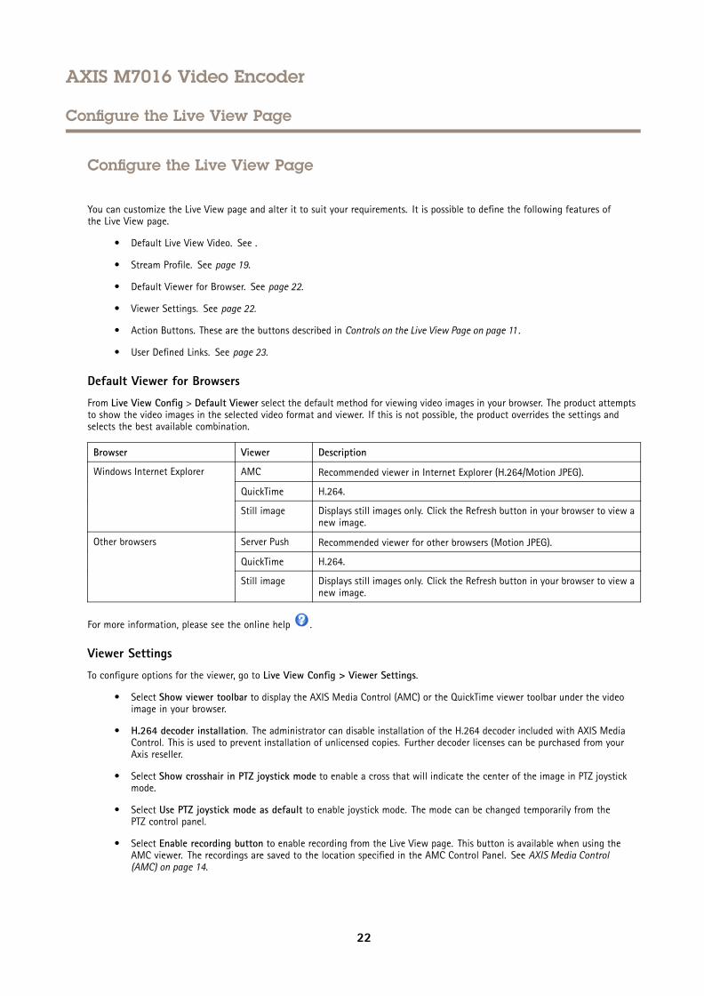
Default Viewer for Browsers
From Live View Config > Default Viewer select the default method for viewing video images in your browser. The product attemptsto show the video images in the selected video format and viewer. If this is not possible, the product overrides the settings andselects the best available combination.
Browser Viewer Description
AMC Recommended viewer in Internet Explorer (H.264/Motion JPEG).
QuickTime H.264.
Windows Internet Explorer
Still image Displays still images only. Click the Refresh button in your browser to view anew image.
Server Push Recommended viewer for other browsers (Motion JPEG).
QuickTime H.264.
Other browsers
Still image Displays still images only. Click the Refresh button in your browser to view anew image.
For more information, please see the online help .
Viewer Settings
To configure options for the viewer, go to Live View Config > Viewer Settings.
• Select Show viewer toolbar to display the AXIS Media Control (AMC) or the QuickTime viewer toolbar under the videoimage in your browser.
• H.264 decoder installation. The administrator can disable installation of the H.264 decoder included with AXIS MediaControl. This is used to prevent installation of unlicensed copies. Further decoder licenses can be purchased from yourAxis reseller.
• Select Show crosshair in PTZ joystick mode to enable a cross that will indicate the center of the image in PTZ joystickmode.
• Select Use PTZ joystick mode as default to enable joystick mode. The mode can be changed temporarily from thePTZ control panel.
• Select Enable recording button to enable recording from the Live View page. This button is available when using theAMC viewer. The recordings are saved to the location specified in the AMC Control Panel. See AXIS Media Control(AMC) on page 14.
22

AXIS M7016 Video Encoder
Configure the Live View Page
User Defined Links
To display user-defined links in the Live View page, select the Show custom link option, give the link a name and then enter the URLto link to. When defining a web link do not remove the 'http://' from the URL address. Custom links can be used to run scripts oractivate external devices connected to the product, or they can link to a web page. Custom links defined as cgi links will run thescript in the background, in a hidden frame. Defining the link as a web link will open the link in a new window.
23
AXIS M7016 Video Encoder
PTZ (Pan Tilt Zoom)
PTZ (Pan Tilt Zoom)
The PTZ menu is available if a PTZ driver has been uploaded. See Install PTZ Driver on page 24.
Preset PositionsA preset position is a saved view that can be used to quickly steer the camera to a specific position. A preset position consists ofthe following values:
• Pan and tilt positions
• Zoom position
• Focus position (manual or automatic)
Guard TourA guard tour displays the video stream from different preset positions, one-by-one, in a predetermined order or at random and forconfigurable time periods. The enabled guard tour will keep running after the user has logged off or closed the browser.
To add a guard tour:
1. Go to PTZ > Guard Tour and click Add.
2. Enter a descriptive name.
3. Specify the pause length between runs.
4. Select an available preset position and click Apply.
5. Specify the Move Speed.
6. Specify the View Time in seconds or minutes.
7. Specify the View Order or select the Random view order option.
8. Click Save.
To modify or remove guard tours, go to PTZ > Guard Tour, select the guard tour in the Guard Tour List and click Modify/Remove.
NoteFor products that support Limited Guard Tour, the product has a fixed minimum view time
For more information see the online help .
Install PTZ DriverThis Axis product supports several PTZ devices. Please see www.axis.com for a complete list of supported devices, and to obtain thecorrect driver. To install a PTZ device you need to install the PTZ driver.
To install the PTZ driver go to PTZ> Driver Selection. Browse to find the driver (e.g. driver.ptz) and Upload. If the driver wassuccessfully uploaded, it appears in the Select driver to use drop-down list. From this drop-down list, select the driver to installor remove, and click Save.
Select Activate PTZ to enable PTZ. The address of the connected device appears against Device ID. Choose the Device type from thedrop-down list. To find which device type to use, consult the documentation supplied by the PTZ driver.
To complete the installation go to System Options > Ports & Devices > COM Port and verify the settings.
24
AXIS M7016 Video Encoder
PTZ (Pan Tilt Zoom)
Advanced
Device Settings
The Device Settings window displays driver specific settings. The appearance of this window can vary depending on the driverinstalled. Options that can be configured include:
• Driver Specific Settings for Video Source
• Mechanical Limits for Moving Video Source
• Light Control Video Source
• Extended Driver Specific Settings for Video Source
For download and installation information about PTZ drivers for your Axis product please visit www.axis.com/techsup/
Controls
Advanced PTZ settings can be configured under PTZ > Advanced > Controls.
The Panel Shortcut Command Buttons list shows the user-defined buttons that can be accessed from the Live View page’s Ctrlpanel. These buttons can be used to provide direct access to commands issued using the VAPIX® application programming interface.Click Add to add a new shortcut command button.
The following PTZ controls are enabled by default:
• Pan control
• Tilt control
• Zoom control
• Focus control
To disable specific controls, deselect the options under Enable/Disable controls.
NoteDisabling PTZ controls will not affect preset positions. For example, if the tilt control is disabled, the product can still move topreset positions that require a tilt movement.
OSD Menu
If the PTZ unit supports an internal configuration menu, this can be accessed using the On-Screen Display (OSD). Configure theanalog camera by opening and navigating through its internal menu in this display.
Control QueueNote
• The administrator can enable and disable PTZ controls for selected users.
• To identify different users in the viewer group, cookies must be enabled on the client.
• The Control queue polltime is measured in seconds. For more information see the online help .
The administrator can set up a queue for PTZ controllers from PTZ > Control Queue. Once set up, the PTZ Control Queue buttonsappear in the Live View page offering one viewer exclusive control for a limited period of time. Other users will be placed in queue.
A user who belongs to a group (see Users on page 42) with a higher PTZ priority can go before other users in the queue and takecontrol of the product. The order of priority is as follows:
25
AXIS M7016 Video Encoder
PTZ (Pan Tilt Zoom)
1. Administrator — An administrator takes over PTZ control regardless of who is first in queue. The administrator will beremoved from the queue 60 seconds after the last PTZ control command.
2. Event — The Axis product can be configured to go to a preset position when triggered by an alarm (see Events on page 33).The event will immediately be placed first in the queue except when an administrator is in control.
3. Operator — Same as administrator but with lower priority
4. Guard Tour — A guard tour (see page 24) has PTZ control for an indefinite period of time. It may be overridden by anoperator, event or administrator. The guard tour will resume when higher priority groups leave the queue.
5. Viewer — Multiple viewers must wait for their turn. The viewer has 60 seconds PTZ control before control is passedon to the next viewer in queue.
26
AXIS M7016 Video Encoder
Detectors
Detectors
Camera TamperingCamera Tampering can generate an alarm whenever the camera is repositioned, or when the lens is covered, spray-painted or severelydefocused. To send an alarm, for example an email, an action rule must be set up.
To configure tampering detection:
1. Go to Detectors > Camera Tampering.
2. Set the Minimum duration, that is, the time that must elapse before an alarm is generated. Increase time to preventfalse alarms for known conditions that affect the image.
3. Select Alarm for dark images if an alarm should be generated if lights are dimmed or turned off, or if the lens is sprayed,covered, or rendered severely out of focus.
4. Click Save.
To configure the product to send an alarm when tampering occurs:
1. Go to Events > Action Rules.
2. Click Add to set up a new action rule.
3. Enter a Name for the action rule.
4. Under Condition, select Detectors from the Trigger list.
5. Select Tampering from the list of detectors.
6. Select the video channel.
7. Optionally, select a schedule and set additional conditions.
8. Select the action. To send an email, select Send Notification and select a Recipient from the list of defined recipients.
NoteTheWhile the rule is active option under Duration cannot be used with camera tampering, since camera tampering does nothave a duration and once it has been triggered it will not automatically return to its untriggered state.
For more information on actions rules, see Events on page 33.
27
AXIS M7016 Video Encoder
AXIS Video Motion Detection
AXIS Video Motion Detection
AXIS Video Motion Detection is an application that detects moving objects in the camera’s field of view. When a moving objectis detected, AXIS Video Motion Detection sends an alarm that can be used by the Axis product or by third-party software to,for example, record video or send a notification.
AXIS Video Motion Detection 3 is included with the Axis product and is available under Setup > Applications. To use AXIS VideoMotion Detection, the application must first be started. To avoid detecting unwanted objects, the application should be configured.During configuration, visual confirmation can be used to help understand the effect of the different filters. When visual confirmationis enabled, red polygons show which objects the application detects and green polygons show which objects the application ignores.
ConsiderationsBefore using AXIS Video Motion Detection 3, take the following into consideration:
• Small and distant objects might not be detected.
• Detection accuracy may be affected by weather conditions such as heavy rain or snow.
• Make sure that the lighting conditions are within the Axis product’s specification. Add additional lighting if needed.
• Make sure that the camera is not subject to excessive vibrations. Vibrations might cause false detections.
Start and Stop the ApplicationTo start the application, select it in the Installed Applications list on the Applications page and click Start.
To stop the application, select it in the list and click Stop.
Configure ApplicationThe application is available from Setup > Applications > Motion Detection 3. Go to Settings and then click AXISAXISAXIS VideoVideoVideo MotionMotionMotionDetectionDetectionDetection settingssettingssettings to open the application’s webpage.
To configure AXIS Video Motion Detection 3, follow these steps:
1. Modify the size and position of the include area. This is the area in which moving objects will be detected. See IncludeArea on page 29.
2. Optionally, add one or more exclude areas. Objects in an exclude area will be ignored. See Exclude Area on page 29.
3. Click Save to apply the changes.
4. Use visual confirmation to verify the settings. See Visual Confirmation on page 29.
5. If too many unwanted objects are detected, enable and configure one or more of the ignore filters. See Ignore Filterson page 30.
After modifying a setting, click Save to apply the changes. The video stream will be restarted and it may take a few secondsbefore the change is applied.
Multichannel Products
To use the application on multiple channels, the application must be enabled and configured for each channel.
• To switch between channels, click on the tabs below the video image.
• To enable the application on a channel, switch to that channel and click Enable.
28
AXIS M7016 Video Encoder
AXIS Video Motion Detection
It is recommended to only enable visual confirmation for one channel at a time. Make sure to disable visual confirmation beforestarting configuring another channel.
Clicking Save will save changes on all channels.
Include Area
The include area is the area in which moving objects will be detected. Objects moving outside the include area will be ignored.The object will be detected also if only a part of the object is inside the include area.
NoteTo modify the include area, Internet Explorer and AXIS Media Control (AMC) must be used.
The default include area is a square that covers the whole image. Click on the icon to highlight the area.
Use the mouse to reshape and resize the area so that it only covers the part of the image in which moving objects should be detected.The default square can be changed to a polygon with up to 20 points (corners).
• To add a new point, click on the include area border. Drag the point to the desired position.
• To remove a point, right-click on the point.
• To move a point, drag the point to the new position.
• To move the entire include area, place the mouse pointer inside the area. When the pointer becomes a cross, drag thearea to the new position.
• To select the include area, click on the border.
To reset the include area to its default size, click Reset.
Exclude Area
An exclude area is an area in which moving objects will be ignored. Use exclude areas if there are areas inside the include areathat trigger a lot of unwanted detected objects. Up to 10 exclude areas can be used.
NoteTo add and modify exclude areas, Internet Explorer and AXIS Media Control (AMC) must be used.
To add an exclude area, click Add. The default exclude area is a rectangle placed in the center of the image. Use the mouseto move, reshape and resize the area so that it covers the desired part of the image. The default square can be changed to apolygon with up to 20 points (corners).
• To move the exclude area, place the mouse pointer inside the area. When the pointer becomes a cross, drag the areato the new position.
• To add a new point, click on the exclude area border. Drag the point to the desired position.
• To remove a point, right-click on the point.
• To move a point, drag the point to the new position.
• To select an exclude area, click on the border.
To remove an exclude area, select the area and then click Remove.
To highlight the exclude areas, click on the icon.
Visual Confirmation
Visual confirmation is used to validate that the settings are correct, that is, that all objects that should be detected are detected.
29
AXIS M7016 Video Encoder
AXIS Video Motion Detection
NoteTo use visual confirmation, Internet Explorer and AXIS Media Control (AMC) must be used.
When visual confirmation is enabled, all moving objects found by the application will be encircled and followed by polygons. A redpolygon indicates that the object is found and is detected as a moving object. A green polygon indicates that the object is found butis ignored because it is not in the include area or because of one of the ignore filters.
To enable visual confirmation:
1. Select the Enable visual confirmation option.
2. Click Save.
Note• Visual confirmation is disabled after 15 minutes.
• After modifying a setting, click Save to apply the change. The video stream will be restarted and it may take a few secondsbefore the change is applied.
• Enabling visual confirmation may introduce video latency.
Ignore Filters
If AXIS Video Motion Detection 3 detects too many unwanted objects, start by modifying the include and exclude areas. If still toomany objects are detected, use one or more of the ignore filters.
Supported ignore filters:
• Swaying objects — Used to ignore objects that only move a short distance
• Short-lived objects — Used to ignore objects that only appear in the image for a short period of time
• Small objects — Used to ignore small objects
Ignore filters are applied to all moving objects found by the application and should be configured with care to ensure that noimportant objects are ignored.
Only use ignore filters if needed and use as few filters as possible. Enable and configure one filter at a time and use visual confirmationto verify the settings before enabling another filter. When configuring a filter, start with a small filter size, click Save and use visualconfirmation to verify the settings. If required, increase the filter size in small steps until the number of unwanted objects is reduced.
Swaying Object Ignore Filter
The swaying object filter is used to avoid detecting objects that only move a short distance, for example moving trees, flags and theirshadows. Use the filter if such objects cause a lot of false detections. If the swaying objects in the scene are large, for example largeponds or large trees, use exclude areas instead of the filter. The filter will be applied to all moving objects in scene and, if set toa value too large, important objects might not be detected.
When the swaying object filter is enabled and the application finds a moving object, the object will not be reported as detected (redpolygon in visual confirmation) until it has travelled a distance larger than the set filter size. The alarm sent by the application will besent when the object is detected. If the alarm is used to start a recording, configure the pre-trigger time so that the recording alsoincludes the time the object moved in the scene before being detected.
To enable the filter:
1. Select the Swaying objects option.
2. Click on the icon to show the filter size in the image.
3. Use the mouse to adjust the filter size. Start with a small size. Objects moving a distance shorter than the distance fromthe center of the cross to one of the arrowheads will be ignored. The filter can be moved to the location of a swayingobject to make it easier to adjust the size. Note that the filter will be applied to all objects in the image, not only to theones at the location where the filter is placed.
30
AXIS M7016 Video Encoder
AXIS Video Motion Detection
4. Click Save to apply the filter.
5. Use visual confirmation to verify the settings.
6. If the result is not satisfactory, increase the filter size in small steps.
The filter size can also be set by entering a value between 10 and 50 in the field. The value corresponds to the distance from thecenter of the cross to one of the arrowheads. The value 100 implies that an object must travel from its initial point to one third of theimage width or height before being detected. The value 50 implies half that distance, that is, the object must travel a distance ofone sixth of the image width or height before being detected.
Short-Lived Object Ignore Filter
The short-lived object filter is used to avoid detecting objects that only appear for a short period of time, such as light beams from apassing car and quickly moving shadows. Use the filter if such objects cause a lot of false detections.
When the short-lived object filter is enabled and the application finds a moving object, the object will not be reported as detected(red polygon in visual confirmation) until the set time as passed. The alarm sent by the application will be sent when the object isdetected. If the alarm is used to start a recording, configure the pre-trigger time so that the recording also includes the time theobject moved in the scene before being detected.
To enable the filter:
1. Select the Short-lived objects option.
2. Enter the number of seconds in the field. The number of seconds is the minimum time that must pass before the object isdetected. Start with a small number.
3. Click Save to apply the filter.
4. Use visual confirmation to verify the settings.
5. If the result is not satisfactory, increase the filter size in small steps.
Small Object Ignore Filter
The small object filter is used to avoid detecting objects that are too small. For example, if only moving cars should be detected, thesmall object filter can be used to avoid detecting people and animals.
If using the small object filter, take into consideration that an object far from the camera appears smaller than an object close to thecamera. If the filter is set to ignore objects the size of a person, people that are close to be camera can still be detected becausethey are larger than the filter size.
To enable the filter:
1. Select the Small objects option.
2. Click on the icon to show the filter size in the image.
3. Use the mouse to adjust the filter size. Start with a small size. Moving objects that fit inside the rectangle will be ignored.The filter displayed in the image can be moved to make it easier to compare the filter size with the size of objectsin the image. Note that the filter will be applied to all objects in the image, also to objects that are not located atthe position of the displayed filter.
4. Click Save to apply the filter.
5. Use visual confirmation to verify the settings.
6. If the result is not satisfactory, increase the filter size in small steps.
The filter size can also be set by entering the width and height in the fields. The width and height are the maximum width andmaximum height of the objects to ignore and are measured in percent of the image width and height. Values between 5 and 100can be used.
31
AXIS M7016 Video Encoder
AXIS Video Motion Detection
Using the Application in an Action RuleThe following example shows how to configure the Axis product to record video when AXIS Video Motion Detection 3 detects motion.
1. Insert an SD card in the Axis product, or go to Setup > System Options > Storage in the Axis product’s webpages andconfigure the product to use a network share.
2. Optionally, go to Setup > Video > Stream Profiles and create a stream profile to use for recording.
3. Go to Setup > Events > Action Rules and click Add to create a new action rule.
4. From the Trigger drop-down list, select Applications and then select VMD 3.
5. Configure other settings as required. For example, to only record video during certain time periods, select a Schedule.
6. Under Actions, select Record Video from the Type drop-down list.
7. Select the stream profile and storage device to use and configure the pre- and post-trigger times.
8. Make sure that the rule is enabled and then click OK.
NoteTo appear in the Trigger list, the application must be started and its status must be Idle or Running.
32
AXIS M7016 Video Encoder
Events
Events
The Event pages allow you to configure the Axis product to perform actions when different events occur. For example, the productcan start a recording or send an email notification when motion is detected. The set of conditions that defines how and whenthe action is triggered is called an action rule.
Convert Event Types to Action RulesIf the Axis product is upgraded to firmware version 5.40 or later, it is recommended to convert Event Types to Action Rules. Thelegacy user Event Types in the camera will continue to work but will not be visible in the user interface of the camera. The EventTypes need to be converted to Action rules to become visible in the user interface.
To convert Event Types to Action Rules go to Events > Action Rules and click Convert.
NONONOTICETICETICEThis is not recommended when using a VMS based on the old Event Management System.
Set Up Action RulesAn action rule defines the conditions that must be met for the product to perform an action, for example record video or send anemail notification. If multiple conditions are defined, all of them must be met to trigger the action.
For more information about available triggers and actions, see Triggers on page 34 and Actions on page 35.
The following example describes how to set up an action rule to record video to a network share if there is movement in thecamera’s field of view.
Set up motion detection and add a network share:
1. Go to Applications to start and configure AXIS Video Motion Detection 3. See AXIS Video Motion Detection.
2. Go to System Options > Storage and set up the network share. See page 52.
Set up the action rule:
1. Go to Events > Action Rules and click Add.
2. Select Enable rule and enter a descriptive name for the rule.
3. Select Applications from the Trigger drop-down list and then select VMD3
4. Optionally, select a Schedule and Additional conditions. See below.
5. Under Actions, select Record Video from the Type drop-down list.
6. Select a Stream profile and configure the Duration settings as described below.
7. Select Network Share from the Storage drop-down list.
To use more than one trigger for the action rule, select Additional conditions and click Add to add additional triggers. When usingadditional conditions, all conditions must be met to trigger the action.
To prevent an action from being triggered repeatedly, a Wait at least time can be set. Enter the time in hours, minutes and seconds,during which the trigger should be ignored before the action rule can be activated again.
The recording Duration of some actions can be set to include time immediately before and after the event. Select Pre-trigger timeand/or Post-trigger time and enter the number of seconds. When While the rule is active is enabled and the action is triggeredagain during the post-trigger time, the recording time will be extended with another post-trigger time period.
For more information, see the online help .
33
AXIS M7016 Video Encoder
Events
Triggers
Available action rule triggers and conditions include:
- VMD3 – Trigger the rule when AXIS Video Motion Detection detects a moving object. See AXIS Video MotionDetection.
• Detectors
- Live Stream Accessed – Trigger the rule when any stream is accessed and during edge storage playback.This can for example be used to send notifications.
- Tampering – Trigger the rule when tampering is detected. See Camera Tampering on page 27.
• Hardware
- Video Signal – Trigger the rule if video signal is lost.
- Network – Trigger the rule if network connection is lost or restored. This can for example be used to startrecording to the SD card.
- Temperature – Trigger the rule if the temperature falls outside or inside the operating range of the product. Thiscan for example be used to send maintenance notifications.
• Input Signal
- Manual Trigger – Trigger the rule using the Manual Trigger button in the Live View page. See Controls onthe Live View Page on page 11 . This can for example be used to validate actions during product installationand configuration.
- Virtual Inputs – can be used by a VMS (Video Management System) to trigger actions. Virtual inputs can, forexample, be connected to buttons in the VMS user interface.
• PTZ
- Error – Trigger the rule if the PTZ functionality is not working correctly. This can for example be used tosend maintenance notifications.
- Ready – Trigger the rule when the PTZ functionality is ready to be used. This can for example be used to steerthe camera to a specific preset position when the product is started.
• Storage
- Disruption – Trigger the rule if storage problems are detected, for example if the storage device is unavailable,removed, full, locked or if other read or write problems occur. This can for example be used to send maintenancenotifications.
- Recording – Triggers the rule when the Axis product records to the storage device. The recording status triggercan be used to notify the operator, for example by flashing LED lights, if the product has started or stopped torecord to the storage device. Note that, this trigger can be used only for edge storage recording status.
• System
- System Ready – Trigger the rule when the product has been started and all services are running. This can forexample be used to send a notification when the product restarts.
• Time
- Recurrence – Trigger the rule periodically. See Set Up Recurrences on page 37. This can for example be used toupload an image every 5 minutes.
- Use Schedule – Trigger the rule according to the selected schedule. See Create Schedules on page 37.
34
AXIS M7016 Video Encoder
Events
Actions
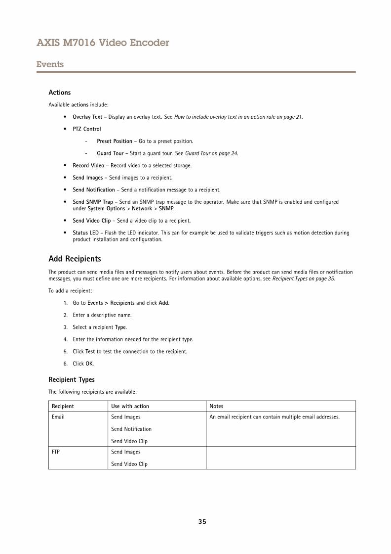
Available actions include:
• Overlay Text – Display an overlay text. See How to include overlay text in an action rule on page 21.
• PTZ Control
- Preset Position – Go to a preset position.
- Guard Tour – Start a guard tour. See Guard Tour on page 24.
• Record Video – Record video to a selected storage.
• Send Images – Send images to a recipient.
• Send Notification – Send a notification message to a recipient.
• Send SNMP Trap – Send an SNMP trap message to the operator. Make sure that SNMP is enabled and configuredunder System Options > Network > SNMP.
• Send Video Clip – Send a video clip to a recipient.
• Status LED – Flash the LED indicator. This can for example be used to validate triggers such as motion detection duringproduct installation and configuration.
Add RecipientsThe product can send media files and messages to notify users about events. Before the product can send media files or notificationmessages, you must define one ore more recipients. For information about available options, see Recipient Types on page 35.
To add a recipient:
1. Go to Events > Recipients and click Add.
2. Enter a descriptive name.
3. Select a recipient Type.
4. Enter the information needed for the recipient type.
5. Click Test to test the connection to the recipient.
6. Click OK.
Recipient Types
The following recipients are available:
Recipient Use with action Notes
Email Send Images
Send Notification
Send Video Clip
An email recipient can contain multiple email addresses.
FTP Send Images
Send Video Clip
35
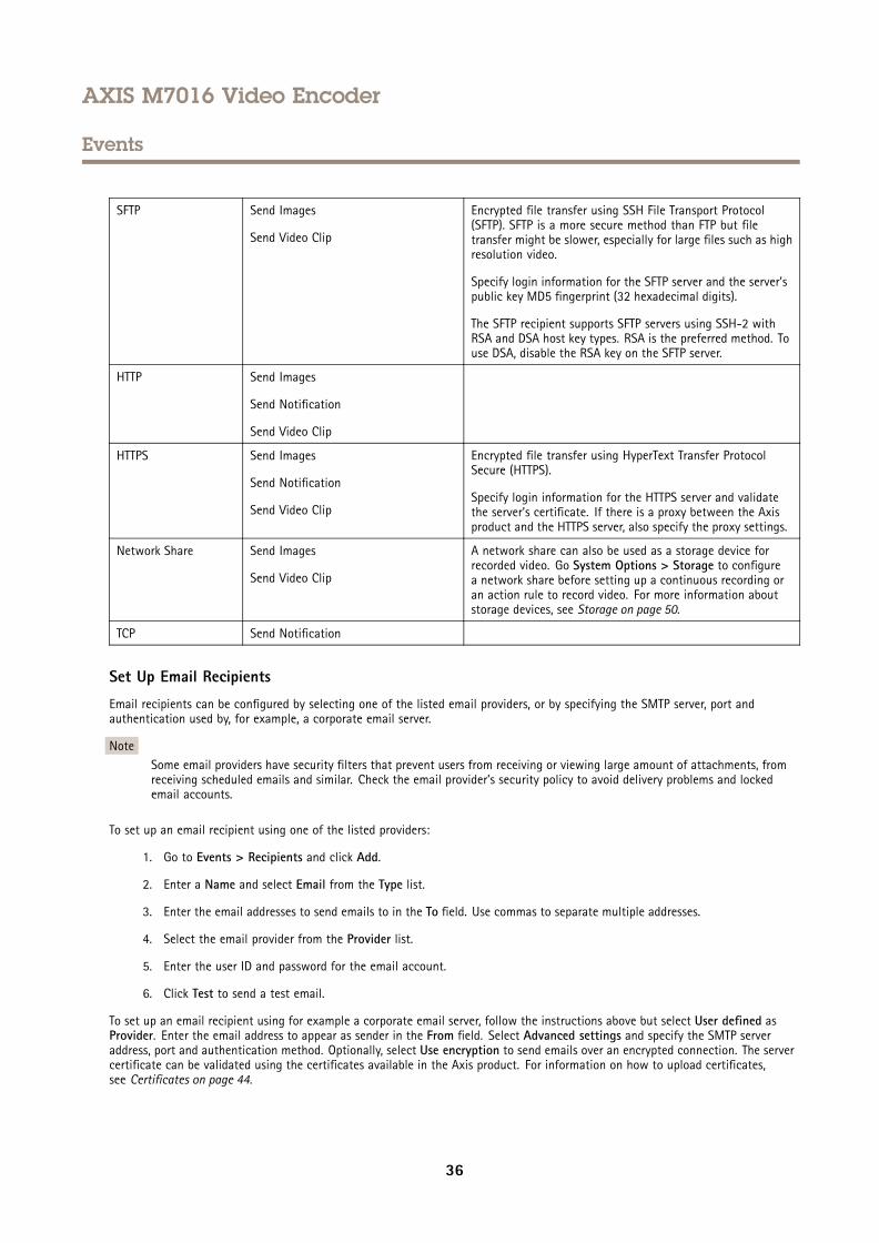
AXIS M7016 Video Encoder
Events
SFTP Send Images
Send Video Clip
Encrypted file transfer using SSH File Transport Protocol(SFTP). SFTP is a more secure method than FTP but filetransfer might be slower, especially for large files such as highresolution video.
Specify login information for the SFTP server and the server’spublic key MD5 fingerprint (32 hexadecimal digits).
The SFTP recipient supports SFTP servers using SSH-2 withRSA and DSA host key types. RSA is the preferred method. Touse DSA, disable the RSA key on the SFTP server.
HTTP Send Images
Send Notification
Send Video Clip
HTTPS Send Images
Send Notification
Send Video Clip
Encrypted file transfer using HyperText Transfer ProtocolSecure (HTTPS).
Specify login information for the HTTPS server and validatethe server’s certificate. If there is a proxy between the Axisproduct and the HTTPS server, also specify the proxy settings.
Network Share Send Images
Send Video Clip
A network share can also be used as a storage device forrecorded video. Go System Options > Storage to configurea network share before setting up a continuous recording oran action rule to record video. For more information aboutstorage devices, see Storage on page 50.
TCP Send Notification
Set Up Email Recipients
Email recipients can be configured by selecting one of the listed email providers, or by specifying the SMTP server, port andauthentication used by, for example, a corporate email server.
NoteSome email providers have security filters that prevent users from receiving or viewing large amount of attachments, fromreceiving scheduled emails and similar. Check the email provider’s security policy to avoid delivery problems and lockedemail accounts.
To set up an email recipient using one of the listed providers:
1. Go to Events > Recipients and click Add.
2. Enter a Name and select Email from the Type list.
3. Enter the email addresses to send emails to in the To field. Use commas to separate multiple addresses.
4. Select the email provider from the Provider list.
5. Enter the user ID and password for the email account.
6. Click Test to send a test email.
To set up an email recipient using for example a corporate email server, follow the instructions above but select User defined asProvider. Enter the email address to appear as sender in the From field. Select Advanced settings and specify the SMTP serveraddress, port and authentication method. Optionally, select Use encryption to send emails over an encrypted connection. The servercertificate can be validated using the certificates available in the Axis product. For information on how to upload certificates,see Certificates on page 44.
36
AXIS M7016 Video Encoder
Events
Create SchedulesSchedules can be used as action rule triggers or as additional conditions, for example to record video if motion is detected outsideoffice hours. Use one of the predefined schedules or create a new schedule as described below.
To create a new schedule:
1. Go to Events > Schedules and click Add.
2. Enter a descriptive name and the information needed for a daily, weekly, monthly or yearly schedule.
3. Click OK.
To use the schedule in an action rule, select the schedule from the Schedule drop-down list in the Action Rule Setup page.
Set Up RecurrencesRecurrences are used to trigger action rules repeatedly, for example every 5 minutes or every hour.
To set up a recurrence:
1. Go to Events > Recurrences and click Add.
2. Enter a descriptive name and recurrence pattern.
3. Click OK.
To use the recurrence in an action rule, first select Time from the Trigger drop-down list in the Action Rule Setup page and thenselect the recurrence from the second drop-down list.
To modify or remove recurrences, select the recurrence in the Recurrences List and click Modify or Remove.
37
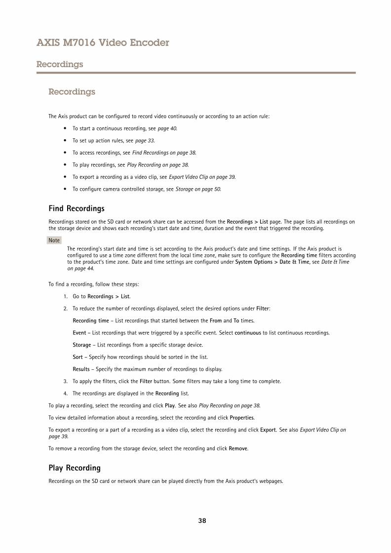
AXIS M7016 Video Encoder
Recordings
Recordings
The Axis product can be configured to record video continuously or according to an action rule:
• To start a continuous recording, see page 40.
• To set up action rules, see page 33.
• To access recordings, see Find Recordings on page 38.
• To play recordings, see Play Recording on page 38.
• To export a recording as a video clip, see Export Video Clip on page 39.
• To configure camera controlled storage, see Storage on page 50.
Find RecordingsRecordings stored on the SD card or network share can be accessed from the Recordings > List page. The page lists all recordings onthe storage device and shows each recording’s start date and time, duration and the event that triggered the recording.
NoteThe recording’s start date and time is set according to the Axis product’s date and time settings. If the Axis product isconfigured to use a time zone different from the local time zone, make sure to configure the Recording time filters accordingto the product’s time zone. Date and time settings are configured under System Options > Date & Time, see Date & Timeon page 44.
To find a recording, follow these steps:
1. Go to Recordings > List.
2. To reduce the number of recordings displayed, select the desired options under Filter:
Recording time – List recordings that started between the From and To times.
Event – List recordings that were triggered by a specific event. Select continuous to list continuous recordings.
Storage – List recordings from a specific storage device.
Sort – Specify how recordings should be sorted in the list.
Results – Specify the maximum number of recordings to display.
3. To apply the filters, click the Filter button. Some filters may take a long time to complete.
4. The recordings are displayed in the Recording list.
To play a recording, select the recording and click Play. See also Play Recording on page 38.
To view detailed information about a recording, select the recording and click Properties.
To export a recording or a part of a recording as a video clip, select the recording and click Export. See also Export Video Clip onpage 39.
To remove a recording from the storage device, select the recording and click Remove.
Play RecordingRecordings on the SD card or network share can be played directly from the Axis product’s webpages.
38
AXIS M7016 Video Encoder
Recordings
To play a recording, follow these steps:
1. Go to Recordings > List.
2. To reduce the number of recordings displayed, select the desired options under Filter and click the Filter button toapply the filters. See also Find Recordings on page 38.
3. Select the recording and click Play. The recording will be played in a new browser window.
Export Video ClipRecordings on the SD card or network share can be exported as video clips. It is possible to export a complete recording or apart of a recording.
NoteThe exported recording is a Matroska video file (.mkv). To play the recording in Windows Media Player, AXIS Matroska FileSplitter must be installed. AXIS Matroska File Splitter can be downloaded from www.axis.com/techsup/software
To export a video clip, follow these steps:
1. Go to Recordings > List.
2. To reduce the number of recordings displayed, select the desired options under Filter and click the Filter button toapply the filters. See also Find Recordings on page 38.
3. Select the recording and click Export. The Export Recording dialog opens.
4. By default, the complete recording is selected. To export a part of the recording, modify the start and stop times.
5. Optionally, enter a file name for the recording.
6. Click Export.
NoteRecordings can also be exported from the playback window.
Recording ListRecorded videos are listed on the Recordings > List page. The list shows each recording’s start date and time, duration and theevent that triggered the recording.
To play or download a recording, follow these steps:
1. Go to Recordings > List.
2. Use the filter to narrow the list of recordings. Enter the desired filter criteria and click Filter. Some filters may takea long time to complete.
3. Select the recording.
4. Click Play to play the recording, or click Download to download the recording.
Multiple recordings can be downloaded at the same time. Select the recordings and click Download. The downloaded file is a zip filecontaining a minimum of three files, of which the Matroska (mkv) files are the actual recordings. The recordings are time-stampedwith the date and time they were downloaded (as opposed to the date the recordings were made).
NoteTo play recordings in Windows Media Player, AXIS Matroska File Splitter must be installed. AXIS Matroska File Splittercan be downloaded from www.axis.com/techsup/software
For detailed recording and video information, select a recording and click Properties.
39
AXIS M7016 Video Encoder
Recordings
To remove a recording, select the recording and click Remove.
Continuous RecordingThe Axis product can be configured to continuously save video to a storage device. For information about storage devices, see Storageon page 50. To prevent the disk from becoming full, it is recommended to configure the disk to automatically remove old recordings.
If a new stream profile is selected while a recording is ongoing, the recording will be stopped and saved in the recording list and anew recording with the new stream profile will start. All previous continuous recordings will remain in the recording list until theyare removed manually or through automatic removal of old recordings.
To start a continuous recording, follow these steps:
1. Go to Recordings > Continuous.
2. Select Enabled.
3. Select the type of storage device from the Storage list.
4. Select a Stream profile to use for continuous recordings.
5. Click Save to save and start the recording.
40
AXIS M7016 Video Encoder
Languages
Languages
Multiple languages can be installed in the Axis product. All web pages including the online help will be displayed in the selectedlanguage. To switch languages, go to Setup > Languages and first upload the new language file. Browse and locate the file and clickthe Upload Language button. Select the new language from the list and click Save.
Note• Resetting the product to factory default settings will erase any uploaded language files and reset the product language toEnglish.
• Clicking the Restore button on the Maintenance page will not affect the language.
• A firmware upgrade will not affect the language used. However if you have uploaded a new language to the product andlater upgrade the firmware, it may happen that the translation no longer matches the product's web pages. In this case,upload an updated language file.
• A language already installed in the product will be replaced when a current or a later version of the language file is uploaded.
41
AXIS M7016 Video Encoder
System Options
System Options
Security
Users
User access control is enabled by default and can be configured under System Options > Security > Users. An administrator canset up other users by giving them user names and passwords. It is also possible to allow anonymous viewer login, which meansthat anybody may access the Live View page.
The user list displays authorized users and user groups (access levels):
• Viewers have access to the Live View page
• Operators have access to all settings except:
- creating and modifying PTZ presets
- creating and modifying PTZ control settings
- creating and modifying privacy mask settings
- uploading applications and language files
- any of the settings included in the System Options
• Administrators have unrestricted access to all settings. The administrator can add, modify and remove other users.
NoteNote that when the option Encrypted & unencrypted is selected, the webserver will encrypt the password. This is the defaultoption for a new unit or a unit reset to factory default settings.
Under HTTP/RTSP Password Settings, select the type of password to allow. You may need to allow unencrypted passwords if there areviewing clients that do not support encryption, or if you upgraded the firmware and existing clients support encryption but needto log in again and be configured to use this functionality.
Under User Settings, select the Enable anonymous viewer login option to allow anonymous users access to the Live View page.
Select the Enable anonymous PTZ control login to allow anonymous users access to the PTZ controls.
Deselect the Enable Basic Setup option to hide the Basic Setup menu. Basic Setup provides quick access to settings that should bemade before using the Axis product.
ONVIF
ONVIF (Open Network Video Interface Forum) is a global interface standard that makes it easier for end users, integrators, consultants,and manufacturers to take advantage of the possibilities offered by network video technology. ONVIF enables interoperabilitybetween different vendor products, increased flexibility, reduced cost and future-proof systems.
By creating a user you automatically enable ONVIF communication. Use the user name and password with all ONVIF communicationwith the product. For more information see www.onvif.org
IP Address Filter
IP address filtering is enabled on the System Options > Security > IP Address Filter page. Once enabled, the listed IP address areallowed or denied access to the Axis product. Select Allow or Deny from the list and click Apply to enable IP address filtering.
The administrator can add up to 256 IP address entries to the list (a single entry can contain multiple IP addresses).
42
AXIS M7016 Video Encoder
System Options
HTTPS
HTTPS (HyperText Transfer Protocol over Secure Socket Layer, or HTTP over SSL) is a web protocol providing encrypted browsing.HTTPS can also be used by users and clients to verify that the correct device is being accessed. The security level provided byHTTPS is considered adequate for most commercial exchanges.
The Axis product can be configured to require HTTPS when users from different user groups (administrator, operator, viewer) log in.
To use HTTPS, an HTTPS certificate must first be installed. Go to System Options > Security > Certificates to install and managecertificates. See Certificates on page 44.
To enable HTTPS on the Axis product:
1. Go to System Options > Security > HTTPS
2. Select an HTTPS certificate from the list of installed certificates.
3. Optionally, click Ciphers and select the encryption algorithms to use for SSL.
4. Set the HTTPS Connection Policy for the different user groups.
5. Click Save to enable the settings.
To access the Axis product via the desired protocol, in the address field in a browser, enter https:// for the HTTPS protocoland http:// for the HTTP protocol.
The HTTPS port can be changed on the System Options > Network > TCP/IP > Advanced page.
IEEE 802.1X
IEEE 802.1X is a standard for port-based Network Admission Control providing secure authentication of wired and wireless networkdevices. IEEE 802.1X is based on EAP (Extensible Authentication Protocol).
To access a network protected by IEEE 802.1X, devices must be authenticated. The authentication is performed by an authenticationserver, typically a RADIUS server, examples of which are FreeRADIUS and Microsoft Internet Authentication Service.
In Axis implementation, the Axis product and the authentication server identify themselves with digital certificates using EAP-TLS(Extensible Authentication Protocol - Transport Layer Security). The certificates are provided by a Certification Authority (CA).You need:
• a CA certificate to authenticate the authentication server.
• a CA-signed client certificate to authenticate the Axis product.
To create and install certificates, go to System Options > Security > Certificates. See Certificates on page 44. Many CA certificatesare preinstalled.
To allow the product to access a network protected by IEEE 802.1X:
1. Go to System Options > Security > IEEE 802.1X.
2. Select a CA Certificate and a Client Certificate from the lists of installed certificates.
3. Under Settings, select the EAPOL version and provide the EAP identity associated with the client certificate.
4. Check the box to enable IEEE 802.1X and click Save.
NoteFor authentication to work properly, the date and time settings in the Axis product should be synchronized with an NTPserver. See Date & Time on page 44.
43
AXIS M7016 Video Encoder
System Options
Certificates
Certificates are used to authenticate devices on a network. Typical applications include encrypted web browsing (HTTPS), networkprotection via IEEE 802.1X and secure upload of images and notification messages for example via email. Two types of certificatescan be used with the Axis product:
Server/Client certificates - To authenticate the Axis product.
CA certificates - To authenticate peer certificates, for example the certificate of an authentication server in case the Axis product isconnected to an IEEE 802.1X protected network.
NoteInstalled certificates, except preinstalled CA certificates, will be deleted if the product is reset to factory default. PreinstalledCA certificates that have been deleted will be reinstalled.
A Server/Client certificate can be self-signed or issued by a Certificate Authority (CA). A self-signed certificate offers limitedprotection and can be used before a CA-issued certificate has been obtained.
To install a self-signed certificate:
1. Go to Setup > System Options > Security > Certificates.
2. Click Create self-signed certificate and provide the requested information.
To create and install a CA-signed certificate:
1. Create a self-signed certificate as described above.
2. Go to Setup > System Options > Security > Certificates.
3. Click Create certificate signing request and provide the requested information.
4. Copy the PEM-formatted request and send to the CA of your choice.
5. When the signed certificate is returned, click Install certificate and upload the certificate.
Server/Client certificates can be installed as Certificate from signing request or as Certificate and private key. Select Certificateand private key if the private key is to be upload as a separate file or if the certificate is in PKCS#12 format.
The Axis product is shipped with several preinstalled CA certificates. If required, additional CA certificates can be installed:
1. Go to Setup > System Options > Security > Certificates.
2. Click Install certificate and upload the certificate.
Date & TimeThe Axis product’s date and time settings are configured under System Options > Date & Time.
Current Server Time displays the current date and time (24h clock). The time can be displayed in 12h clock in the text overlay (seebelow).
To change the date and time settings, select the preferred Time mode under New Server Time:
• Synchronize with computer time – Sets date and time according to the computer’s clock. With this option, date andtime are set once and will not be updated automatically.
• Synchronize with NTP Server – Obtains date and time from an NTP server. With this option, date and time settings areupdated continuously. For information on NTP settings, see NTP Configuration on page 47.
If using a host name for the NTP server, a DNS server must be configured. See DNS Configuration on page 47.
• Set manually – Allows you to manually set date and time.
44
AXIS M7016 Video Encoder
System Options
If using an NTP server, select your Time zone from the drop-down list. If required, check Automatically adjust for daylight savingtime changes.
The Date & Time Format Used in Images is the date and time format displayed as a text overlay in the video stream. Use the
predefined formats or see File Naming & Date/Time Formats in the online help for information on how to create custom date andtime formats. To include date and time in the overlay text, go to Video and select Include date and Include time.
Network
Basic TCP/IP Settings
The Axis product supports IP version 4 and IP version 6. Both versions can be enabled simultaneously, and at least one versionmust always be enabled.
IPv4 Address Configuration
By default, the Axis product is set to use IPv4 (IP version 4) and to obtain the IP address automatically via DHCP. The IPv4 settings areconfigured under System Options > Network > TCP/IP > Basic.
DHCP (Dynamic Host Configuration Protocol) allows network administrators to centrally manage and automate the assignment ofIP addresses. DHCP should only be enabled if using dynamic IP address notification, or if the DHCP can update a DNS server. It isthen possible to access the Axis product by name (host name).
If DHCP is enabled and the product cannot be accessed, run AXIS IP Utility to search the network for connected Axis products, or resetthe product to the factory default settings (see page 54) and then perform the installation again.
To use a static IP address, check Use the following IP address and specify the IP address, subnet mask and default router.
IPv6 Address Configuration
If IPv6 (IP version 6) is enabled, the Axis product will receive an IP address according to the configuration in the network router.
To enable IPv6, go to System Options > Network > TCP/IP > Basic. Other settings for IPv6 should be configured in the network router.
ARP/Ping
The product’s IP address can be assigned using ARP and Ping. For instructions, see Assign IP Address Using ARP/Ping on page 45.
The ARP/Ping service is enabled by default but is automatically disabled two minutes after the product is started, or as soon as an IPaddress is assigned. To re-assign IP address using ARP/Ping, the product must be restarted to enable ARP/Ping for an additionaltwo minutes.
To disable the service, go to System Options > Network > TCP/IP > Basic and clear the option Enable ARP/Ping setting of IP address.
Pinging the product is still possible when the service is disabled.
Assign IP Address Using ARP/Ping
The product's IP address can be assigned using ARP/Ping. The command must be issued within 2 minutes of connecting power.
1. Acquire a free static IP address on the same network segment as the computer.
2. Locate the serial number (S/N) on the product label.
3. Open a command prompt and enter the following commands:
Linux/Unix syntax
arp -s <IP address> <serial number> tempping -s 408 <IP address>
45
AXIS M7016 Video Encoder
System Options
Linux/Unix example
arp -s 192.168.0.125 00:40:8c:18:10:00 tempping -s 408 192.168.0.125
Windows syntax (this may require that you run the command prompt as an administrator)
arp -s <IP address> <serial number>ping -l 408 -t <IP address>
Windows example (this may require that you run the command prompt as an administrator)
arp -s 192.168.0.125 00-40-8c-18-10-00ping -l 408 -t 192.168.0.125
4. Check that the network cable is connected and then restart the product by disconnecting and reconnecting power.
5. Close the command prompt when the product responds with Reply from 192.168.0.125:... or similar.
6. Open a browser and type http://<IP address> in the Location/Address field.
For other methods of assigning the IP address, see the document Assign an IP Address and Access the Video Stream on Axis Supportweb at www.axis.com/techsup
Note• To open a command prompt in Windows, open the Start menu and type cmd in the Run/Search field.
• To use the ARP command in Windows 8/Windows 7/Windows Vista, right-click the command prompt icon and selectRun as administrator.
• To open a command prompt in Mac OS X, open the Terminal utility from Application > Utilities.
AXIS Video Hosting System (AVHS)
AVHS used in conjunction with an AVHS service, provides easy and secure Internet access to live and recorded video accessible fromany location. For more information and help to find a local AVHS Service Provider go to www.axis.com/hosting
The AVHS settings are configured under System Options > Network > TCP IP > Basic. The possibility to connect to an AVHS serviceis enabled by default. To disable, clear the Enable AVHS box.
One-click enabled - Press and hold the product’s control button (see Hardware Overview on page 7 ) for about 3 seconds toconnect to an AVHS service over the Internet. Once registered, Always will be enabled and the Axis product stays connected tothe AVHS service. If the product is not registered within 24 hours from when the button is pressed, the product will disconnectfrom the AVHS service.
Always - The Axis product will constantly attempt to connect to the AVHS service over the Internet. Once registered the product willstay connected to the service. This option can be used when the product is already installed and it is not convenient to use theone-click installation.
AXIS Internet Dynamic DNS Service
AXIS Internet Dynamic DNS Service assigns a host name for easy access to the product. For more information, see www.axiscam.net
To register the Axis product with AXIS Internet Dynamic DNS Service, go to System Options > Network > TCP/IP > Basic. UnderServices, click the AXIS Internet Dynamic DNS Service Settings button (requires access to the Internet). The domain name currentlyregistered at AXIS Internet Dynamic DNS service for the product can at any time be removed.
NoteAXIS Internet Dynamic DNS Service requires IPv4.
46
AXIS M7016 Video Encoder
System Options
Advanced TCP/IP Settings
DNS Configuration
DNS (Domain Name Service) provides the translation of host names to IP addresses. The DNS settings are configured under SystemOptions > Network > TCP/IP > Advanced.
Select Obtain DNS server address via DHCP to use the DNS settings provided by the DHCP server.
To make manual settings, select Use the following DNS server address and specify the following:
Domain name - Enter the domain(s) to search for the host name used by the Axis product. Multiple domains can be separated bysemicolons. The host name is always the first part of a fully qualified domain name, for example, myserver is the host name in thefully qualified domain name myserver.mycompany.com where mycompany.com is the domain name.
Primary/Secondary DNS server - Enter the IP addresses of the primary and secondary DNS servers. The secondary DNS server isoptional and will be used if the primary is unavailable.
NTP Configuration
NTP (Network Time Protocol) is used to synchronize the clock times of devices in a network. The NTP settings are configured underSystem Options > Network > TCP/IP > Advanced.
Select Obtain NTP server address via DHCP to use the NTP settings provided by the DHCP server.
To make manual settings, select Use the following NTP server address and enter the host name or IP address of the NTP server.
Host Name Configuration
The Axis product can be accessed using a host name instead of an IP address. The host name is usually the same as the assigned DNSname. The host name is configured under System Options > Network > TCP/IP > Advanced.
Select Obtain host name via IPv4 DHCP to use host name provided by the DHCP server running on IPv4.
Select Use the host name to set the host name manually.
Select Enable dynamic DNS updates to dynamically update local DNS servers whenever the Axis product’s IP address changes.
For more information, see the online help .
Link-Local IPv4 Address
Link-Local Address is enabled by default and assigns the Axis product an additional IP address which can be used to accessthe product from other hosts on the same segment on the local network. The product can have a Link-Local IP and a staticor DHCP-supplied IP address at the same time.
This function can be disabled under System Options > Network > TCP/IP > Advanced.
HTTP
The HTTP port used by the Axis product can be changed under System Options > Network > TCP/IP > Advanced. In addition to thedefault setting, which is 80, any port in the range 1024–65535 can be used.
HTTPS
The HTTPS port used by the Axis product can be changed under System Options > Network > TCP/IP > Advanced. In addition tothe default setting, which is 443, any port in the range 1024–65535 can be used.
To enable HTTPS, go to System Options > Security > HTTPS. For more information, see HTTPS on page 43.
47
AXIS M7016 Video Encoder
System Options
NAT traversal (port mapping) for IPv4
A network router allows devices on a private network (LAN) to share a single connection to the Internet. This is done by forwardingnetwork traffic from the private network to the “outside”, that is, the Internet. Security on the private network (LAN) is increasedsince most routers are pre-configured to stop attempts to access the private network (LAN) from the public network (Internet).
Use NAT traversal when the Axis product is located on an intranet (LAN) and you wish to make it available from the other (WAN) sideof a NAT router. With NAT traversal properly configured, all HTTP traffic to an external HTTP port in the NAT router is forwarded tothe product.
NAT traversal is configured under System Options > Network > TCP/IP > Advanced.
Note• For NAT traversal to work, this must be supported by the router. The router must also support UPnPTM.
• In this context, router refers to any network routing device such as a NAT router, Network router, Internet Gateway,Broadband router, Broadband sharing device, or a software such as a firewall.
Enable/Disable - When enabled, the Axis product attempts to configure port mapping in a NAT router on your network, using UPnPTM.Note that UPnPTM must be enabled in the product (see System Options > Network > UPnP).
Use manually selected NAT router - Select this option to manually select a NAT router and enter the IP address for the router inthe field. If no router is specified, the product automatically searches for NAT routers on your network. If more than one router isfound, the default router is selected.
Alternative HTTP port - Select this option to manually define an external HTTP port. Enter a port in the range 1024–65535. If theport field is empty or contains the default setting, which is 0, a port number is automatically selected when enabling NAT traversal.
Note• An alternative HTTP port can be used or be active even if NAT traversal is disabled. This is useful if your NAT router does notsupport UPnP and you need to manually configure port forwarding in the NAT router.
• If you attempt to manually enter a port that is already in use, another available port is automatically selected.
• When the port is selected automatically it is displayed in this field. To change this, enter a new port number and click Save.
FTP
The FTP server running in the Axis product enables upload of new firmware, user applications, etc. The FTP server can be disabledunder System Options > Network > TCP/IP > Advanced.
NoteThis FTP server has nothing to do with the product’s ability to transfer images via FTP to other locations and servers.
RTSP
The RTSP server running in the Axis product allows a connecting client to start an H.264 stream. The RTSP port number can bechanged under System Options > Network > TCP/IP > Advanced. The default port is 554.
NoteH.264 video streams will not be available if the RTSP server is disabled.
SOCKS
SOCKS is a networking proxy protocol. The Axis product can be configured to use a SOCKS server to reach networks on the otherside of a firewall or proxy server. This functionality is useful if the Axis product is located on a local network behind a firewall, andnotifications, uploads, alarms, etc need to be sent to a destination outside the local network (for example the Internet).
SOCKS is configured under System Options > Network > SOCKS. For more information, see the online help .
48
AXIS M7016 Video Encoder
System Options
QoS (Quality of Service)
QoS (Quality of Service) guarantees a certain level of a specified resource to selected traffic on a network. A QoS-aware networkprioritizes network traffic and provides a greater network reliability by controlling the amount of bandwidth an application may use.
The QoS settings are configured under System Options > Network > QoS. Using DSCP (Differentiated Services Codepoint) values, theAxis product can mark different types of traffic.
SMTP (email)
To send email messages from the Axis product via SMTP (Simple Mail Transfer Protocol), an SMTP mail server must be set up. Thisis done under System Options > Network > SMTP (email).
Enter the host names or IP addresses and port numbers for the primary and secondary mail servers in the fields provided. A Fromemail address is also required. If the mail server requires authentication, check Use authentication to log in to this server and enterthe necessary information.
SNMP
The Simple Network Management Protocol (SNMP) allows remote management of network devices. An SNMP community is thegroup of devices and management station running SNMP. Community names are used to identify groups.
AXIS Video MIB (Management Information Base) for video hardware can be used to monitor Axis-specific, hardware-relatedissues that may need administrative attention. For more information about AXIS Video MIB and to download MIB files, go towww.axis.com/techsup
To enable and configure SNMP in the Axis product, go to the System Options > Network > SNMP page.
Depending on the level of security required, select the version on SNMP to use.
Traps are used by the Axis product to send messages to a management system on important events and status changes. Check Enabletraps and enter the IP address where the trap message should be sent and the Trap community that should receive the message.
NoteIf HTTPS is enabled, SNMP v1 and SNMP v2c should be disabled.
Traps for SNMP v1/v2 are used by the Axis product to send messages to a management system on important events and statuschanges. Check Enable traps and enter the IP address where the trap message should be sent and the Trap community thatshould receive the message.
The following traps are available:
• Cold start
• Warm start
• Link up
• Authentication failed
NoteAll AXIS Video MIB traps are enabled when SNMP v1/v2c traps are enabled. It is not possible to turn on or off specific traps.
SNMP v3 provides encryption and secure passwords. To use traps with SNMP v3, an SNMP v3 management application is required.
To use SNMP v3, HTTPS must be enabled, see HTTPS on page 43. To enable SNMP v3, check the box and provide the initial userpassword.
NoteThe initial password can only be set once. If the password is lost, the Axis product must be reset to factory default, seeReset to Factory Default Settings on page 54.
49
AXIS M7016 Video Encoder
System Options
UPnPTM
The Axis product includes support for UPnPTM. UPnPTM is enabled by default and the product is automatically detected by operatingsystems and clients that support this protocol.
UPnPTM can be disabled under System Options > Network > UPnP
RTP/H.264
The RTP port range and multicast settings are configured under System Options > Network > RTP.
The RTP port range defines the range of ports from which the video ports are automatically selected. For multicast streams, onlycertain IP addresses and port numbers should be used.
Select Always Multicast Video to start multicast streaming without opening an RTSP session.
Bonjour
The Axis product includes support for Bonjour. Bonjour is enabled by default and the product is automatically detected by operatingsystems and clients that support this protocol.
Bonjour can be disabled under System Options > Network > Bonjour.
Storage
SD Card
NONONOTICETICETICETo prevent data corruption, the SD card should be unmounted before removal.
NoteFor SD card recommendations see www.axis.com
The Axis product supports microSD/microSDHC/microSDXC cards.
The following SD card file systems are supported:
• ext4 — recommended due to its resilience against data loss if the card is ejected or if there is abrupt power loss. To accessdata stored on the card from the Windows operating system, a third-party ext4 driver or application is required.
• vFAT — supported by most operating systems for personal computers.
The SD card is managed on the System Options > Storage page. Click SD Card to open Storage Management.
If the card’s status shows as failed, click Check disk to see if the problem can be found and then try Repair. This option is onlyavailable for SD cards with ext4. For SD cards with vFAT, use a card reader or computer to troubleshoot the card.
To avoid filling the card, it is recommended to remove recordings continuously. Under General Settings, select Remove recordingsolder than and select the number of days or weeks.
To stop writing to the card and protect recordings from being removed, select Lock under General Settings.
Mount and Unmount SD Card
NONONOTICETICETICETo prevent corruption of recordings, the SD card should always be unmounted before it is ejected.
The SD card is automatically mounted when the card is inserted into the Axis product or when the product is started. A manualmount is only required if the card has been unmounted and not ejected and re-inserted.
50
AXIS M7016 Video Encoder
System Options
To unmount the SD card:
1. Open the Axis product’s webpages and go to Setup > System Options > Storage.
2. Click SD Card.
3. Click Unmount.
4. The card can now be removed.
Format SD Card
NONONOTICETICETICEFormatting the SD card will remove all data and recordings stored on the card.
The Axis product can be configured to automatically format SD cards that are inserted into the product. If autoformat is enabled andan SD card is inserted, the product will check if the SD card has the ext4 file system. If the card has a different file system, thecard will automatically be formatted to ext4.
ImportantIf autoformat is enabled, only use new or empty SD cards. Any data stored on the card will be lost when the card is insertedinto the Axis product.
To enable automatic formatting, follow these steps:
1. Open the Axis product’s webpages and go to Setup > System Options > Storage.
2. Click SD Card.
3. Under General Settings, select Autoformat to.
4. Click OK to save settings.
An SD card inserted into the product can be manually formatted to one of the supported file systems. To manually format theSD card, follow these steps:
1. Insert the SD card in the SD card slot.
2. Open the Axis product’s webpages and go to Setup > System Options > Storage.
3. Click SD Card.
4. Click Format and select the desired file system.
5. Click OK to start formatting the card.
Encrypt SD Card Data
To prevent unauthorized individuals and systems from accessing recorded video, the SD card content can be encrypted. Encryptioncan only be enabled when the card is unmounted. After enabling encryption, the SD card must be formatted so that no unencrypteddata remains on the card. The card must also be mounted before it can be used.
NoteIf autoformat is enabled, the card will be formatted and mounted automatically when encryption is enabled. The format andmount steps below should then be skipped.
To encrypt the SD card content:
1. Open the Axis product’s webpages and go to Setup > System Options > Storage.
2. Click SD Card to open Storage Management.
51
AXIS M7016 Video Encoder
System Options
3. If the SD card is mounted, click Unmount to unmount the card.
4. Click Encrypt.
5. Select Enable SD card encryption and enter a passphrase.
6. Back in Storage Management, click Format to format the SD card.
7. Click Mount to mount the SD card.
It is possible to change the passphrase without reformatting the card. Open Storage Management, click Encrypt and enter the oldand new passphrases. The passphrase can only be changed when the card is mounted. Ongoing recordings will not be affected ifthe passphrase is changed.
To disable encryption, unmount the SD card and follow the steps above but clear the Enable SD card encryption option. The cardmust be formatted and mounted when encryption has been disabled.
Network Share
Network share allows you to add network storage such as a NAS (network-attached storage). The NAS shall be dedicated forrecordings and data from the Axis products connected to the network. For information about reference NAS devices, go towww.axis.com/products/axis-camera-companion/support-and-documentation
NoteFor NAS recommendations see www.axis.com
To add a network share:
1. Go to System Options > Storage.
2. Click Network Share.
3. Enter the IP address, DNS or Bonjour name to the host server in the Host field.
4. Enter the name of the share in the Share field. Sub folders cannot be used.
5. If required, select The share requires login and enter the user name and password.
6. Click Connect.
To clear all recordings and data from the Axis product’s folder on the designated share, click Clear under Storage Tools.
To avoid filling the share, it is recommended to remove recordings continuously. Under Recording Settings, select Remove recordingsolder than and select the number of days or weeks.
To stop writing to the share and protect recordings from being removed, select Lock under Recording Settings.
Ports & Devices
COM Port
The Axis product has one RS-485/RS-422 serial port. The port supports the following modes:
• Generic HTTP allows the Axis product to receive data and send commands via HTTP.
• Pan Tilt Zoom is used to control a PTZ device. The PTZ device requires a driver. See Install PTZ Driver for more information.Drivers can be downloaded from www.axis.com
• Generic TCP/IP allows the Axis product to receive data and send commands via TCP/IP.
Select the desired Port Type from the drop-down list. For more information, see the online help .
52
AXIS M7016 Video Encoder
System Options
Port Status
The list on the System Options > Ports & Devices > Port Status page shows the status of the product’s input and output ports.
MaintenanceThe Axis product provides several maintenance functions. These are available under System Options > Maintenance.
Click Restart to perform a correct restart if the Axis product is not behaving as expected. This will not affect any of the currentsettings.
NoteA restart clears all entries in the Server Report.
Click Restore to reset most settings to the factory default values. The following settings are not affected:
• the boot protocol (DHCP or static)
• the static IP address
• the default router
• the subnet mask
• the system time
• the IEEE 802.1X settings
Click Default to reset all settings, including the IP address, to the factory default values. This button should be used with caution. TheAxis product can also be reset to factory default using the control button, see Reset to Factory Default Settings on page 54.
To identify the product or test the Status LED, click Flash LED under Identify and specify the duration in seconds, minutes or hours.This can be useful for identifying the product among other products installed in the same location.
For information about firmware upgrade, see Upgrade the Firmware on page 56.
Support
Support Overview
The System Options > Support > Support Overview page provides information on troubleshooting and contact information,should you require technical assistance.
See also Troubleshooting on page 56.
System Overview
To get an overview of the Axis product’s status and settings, go to System Options > Support > System Overview. Information thatcan be found here includes firmware version, IP address, network and security settings, event settings, image settings and recent logitems. Many of the captions are links to the proper Setup page.
Logs & Reports
The System Options > Support > Logs & Reports page generates logs and reports useful for system analysis and troubleshooting. Ifcontacting Axis Support, please provide a valid Server Report with your query.
System Log - Provides information about system events.
Access Log - Lists all failed attempts to access the product. The Access Log can also be configured to list all connections to theproduct (see below).
53
AXIS M7016 Video Encoder
System Options
Server Report - Provides information about the product status in a pop-up window. The Access Log is automatically includedin the Server Report.
You can view or download the server report. Downloading the server report creates a .zip file that contains a complete server reporttext file in UTF–8 format. Select the Include snapshot with default image settings option to include a snapshot of the product’s LiveView. The server report .zip file should always be included when contacting support.
Parameter List - Shows the product's parameters and their current settings. This may prove useful when troubleshooting orwhen contacting Axis Support.
Connection List - Lists all clients that are currently accessing media streams.
Crash Report - Generates an archive with debugging information. The report takes several minutes to generate.
Advanced
Scripting
Scripting allows experienced users to customize and use their own scripts.
NONONOTICETICETICEImproper use may cause unexpected behavior and loss of contact with the Axis product.
Axis strongly recommends that you do not use this function unless you understand the consequences. Axis Support does not provideassistance for problems with customized scripts.
To open the Script Editor, go to System Options > Advanced > Scripting. If a script causes problems, reset the product to itsfactory default settings, see page 54.
For more information, see www.axis.com/developer
File Upload
Files, for example webpages and images, can be uploaded to the Axis product and used as custom settings. To upload a file, goto System Options > Advanced > File Upload.
Uploaded files are accessed through http://<ip address>/local/<user>/<file name> where <user> is theselected user group (viewer, operator or administrator) for the uploaded file.
Plain Config
Plain Config is for advanced users with experience of Axis product configuration. Most parameters can be set and modified fromthis page.
To open Plain Config, go to System Options > Advanced > Plain Config. Axis Support does not provide assistance.
Reset to Factory Default SettingsImportant
Reset to factory default should be used with caution. A reset to factory default will reset all settings, including the IPaddress, to the factory default values.
NoteThe installation and management software tools are available from the support pages on www.axis.com/techsup
For products with multiple IP addresses channel 1 will have the address 192.168.0.90, channel 2 will have the address192.168.0.91 and so on.
54
AXIS M7016 Video Encoder
System Options
To reset the product to the factory default settings:
1. Disconnect power from the product.
2. Press and hold the control button and reconnect power. See Hardware Overview on page 7 .
3. Keep the control button pressed for 15–30 seconds until the status LED indicator flashes amber.
4. Release the control button. The process is complete when the status LED indicator turns green. The product has been resetto the factory default settings. If no DHCP server is available on the network, the default IP address is 192.168.0.90
5. Using the installation and management software tools, assign an IP address, set the password, and access the video stream.
NoteTo reset a single channel to the original factory default settings, use the button provided in that product’s webpage.
It is also possible to reset parameters to factory default via the web interface. Go to Setup > System Options > Maintenance andclick Default.
55
AXIS M7016 Video Encoder
Troubleshooting
Troubleshooting
Check the FirmwareFirmware is software that determines the functionality of network devices. One of your first actions when troubleshooting a problemshould be to check the current firmware version. The latest version may contain a correction that fixes your particular problem. Thecurrent firmware version in the Axis product is displayed in the page Setup > Basic Setup and in Setup > About.
Upgrade the FirmwareImportant
• Your dealer reserves the right to charge for any repair attributable to faulty upgrade by the user.
• Preconfigured and customized settings are saved when the firmware is upgraded (providing the features are available in thenew firmware) although this is not guaranteed by Axis Communications AB.
Note• After the upgrade process has completed, the product will restart automatically. If restarting the product manually after theupgrade, wait 10 minutes even if you suspect the upgrade has failed.
• When you upgrade the Axis product with the latest firmware from Axis website, the product receives the latest functionalityavailable. Always read the upgrade instructions and release notes available with each new release before upgradingthe firmware.
To upgrade the product’s firmware:
1. Download the latest firmware file to your computer, available free of charge at www.axis.com/techsup
2. Go to Setup > System Options > Maintenance in the product’s webpages.
3. Under Upgrade Server, click Browse and locate the file on your computer.
4. Click Upgrade.
5. Wait approximately 10 minutes while the product is being upgraded and restarted. Then access the product.
AXIS Camera Management can be used for multiple upgrades. See www.axis.com for more information.
Emergency Recovery Procedure
If power or network connection is lost during the upgrade, the process fails and the product may become unresponsive. Flashingred Status indicator indicates a failed upgrade. To recover the product, follow the steps below. The serial number is found onthe product’s label.
1. In UNIX/Linux, type the following from the command line:
arp -s <IP address> <serial number> tempping -l 408 <IP address>
In Windows, type the following from a command/DOS prompt (this may require that you run the command prompt asan administrator):
arp -s <IP address> <serial number>ping -l 408 -t <IP address>
2. If the product does not reply in 30 seconds, restart it and wait for a reply. Press CTRL+C to stop Ping.
3. Open a browser and type in the product’s IP address. In the page that opens, use the Browse button to select the upgradefile to use. Then click Load to restart the upgrade process.
56
AXIS M7016 Video Encoder
Troubleshooting
4. After the upgrade is complete (1–10 minutes), the product automatically restarts and shows a steady green on theStatus indicator.
5. Reinstall the product, referring to the Installation Guide.
If the emergency recovery procedure does not get the product up and running again, contact Axis support at www.axis.com/techsup/
Symptoms, Possible Causes and Remedial ActionsProblems setting the IP address
When using ARP/Ping Try the installation again. The IP address must be set within two minutes after power has beenapplied to the product. Ensure the Ping length is set to 408. For instructions, see Assign IP AddressUsing ARP/Ping on page 45.
The product is located on adifferent subnet
If the IP address intended for the product and the IP address of the computer used to access theproduct are located on different subnets, you will not be able to set the IP address. Contact yournetwork administrator to obtain an IP address.
The IP address is being usedby another device
Disconnect the Axis product from the network. Run the Ping command (in a Command/DOSwindow, type ping and the IP address of the product):
• If you receive: Reply from <IP address>: bytes=32; time=10...this means that the IP address may already be in use by another device on the network.Obtain a new IP address from the network administrator and reinstall the product.
• If you receive: Request timed out, this means that the IP address is availablefor use with the Axis product. Check all cabling and reinstall the product.
Possible IP address conflictwith another device on thesame subnet.
The static IP address in the Axis product is used before the DHCP server sets a dynamic address.This means that if the same default static IP address is also used by another device, there maybe problems accessing the product.
The product cannot be accessed from a browser
Cannot log in When HTTPS is enabled, ensure that the correct protocol (HTTP or HTTPS) is used when attemptingto log in. You may need to manually type http or https in the browser’s address field.
If the password for the user root is lost, the product must be reset to the factory default settings.See Reset to Factory Default Settings on page 54.
The IP address has beenchanged by DHCP
IP addresses obtained from a DHCP server are dynamic and may change. If the IP address hasbeen changed, use AXIS IP Utility or AXIS Camera Management to locate the product on thenetwork. Identify the product using its model or serial number, or by the DNS name (if the namehas been configured).
If required, a static IP address can be assigned manually. For instructions, see the document Assignan IP Address and Access the Video Stream on Axis Support web at www.axis.com/techsup.
Certificate error when usingIEEE 802.1X
For authentication to work properly, the date and time settings in the Axis product should besynchronized with an NTP server. See Date & Time on page 44.
The product is accessible locally but not externally
Router configuration To configure your router to allow incoming data traffic to the Axis product, enable the NAT-traversalfeature which will attempt to automatically configure the router to allow access to the Axisproduct, see NAT traversal (port mapping) for IPv4 on page 48. The router must support UPnPTM.
Firewall protection Check the Internet firewall with your network administrator.
Default routers required Check if you need to configure the router settings from System Options > Network > TCP/IP >Basic.
57
AXIS M7016 Video Encoder
Troubleshooting
Problems with streaming H.264
Problems with AXIS MediaControl (Internet Exploreronly)
To enable the updating of video images in Internet Explorer, set the browser to allow ActiveXcontrols. Also, make sure that AXIS Media Control is installed on your computer.
No H.264 displayed in theclient
Check that the relevant H.264 connection methods and correct interface are enabled in the AMCControl Panel (streaming tab). See AXIS Media Control (AMC) on page 14.
In the AMC Control Panel, select the H.264 tab and click Set to default H.264 decoder.
Check that RTSP is enabled under System Options > Network > TCP/IP > Advanced.
Multicast H.264 onlyaccessible by local clients
Check if your router supports multicasting, or if the router settings between the client and theproduct need to be configured. The TTL (Time To Live) value may need to be increased.
No multicast H.264displayed in the client
Check with your network administrator that the multicast addresses used by the Axis productare valid for your network.
Check with your network administrator to see if there is a firewall preventing viewing.
Poor rendering of H.264images
Ensure that your graphics card is using the latest driver. The latest drivers can usually bedownloaded from the manufacturer’s website.
Color saturation is differentin H.264 and Motion JPEG
Modify the settings for your graphics adapter. Refer to the adapter’s documentation for moreinformation.
Lower frame rate thanexpected
See Performance Considerations on page 62.
Reduce the number of applications running on the client computer.
Limit the number of simultaneous viewers.
Check with the network administrator that there is enough bandwidth available.
Check in the AMC Control Panel (H.264 tag) that video processing is NOT set to Decode onlykey frames.
Lower the image resolution.
The maximum frames per second is dependent on the utility frequency (60/50 Hz) of the Axisproduct. See Technical Specifications on page 60.
Status and Network indicator LEDs are flashing red rapidly
Hardware failure Contact your Axis reseller.
Product does not start up
Product does not start up If the product does not start up keep the network cable connected and re-insert the power cableto the midspan.
Video and image problems, general
Image unsatisfactory Check the video stream and camera settings under Setup > Video > Video Stream and Setup >Video > Camera Settings.
58
AXIS M7016 Video Encoder
Troubleshooting
Storage and disk management problems
Storage disruption A storage disruption alarm is sent if a storage device is unavailable, removed, full, locked or if otherread or write problems occur. To identify the source of the problem, check the System Log underSystem Options > Support > Logs & Reports. Depending on the problem, it might be necessary tore-mount the storage device.
For information on how to set up a storage disruption alarm, see Events on page 33.
Video cannot be recorded Check that the SD card is not write protected (that is, read only).
SD card cannot be mounted Reformat the SD card and then click Mount.
NONONOTICETICETICEFormatting the card will remove all content, including all recordings, from the SD card.
59
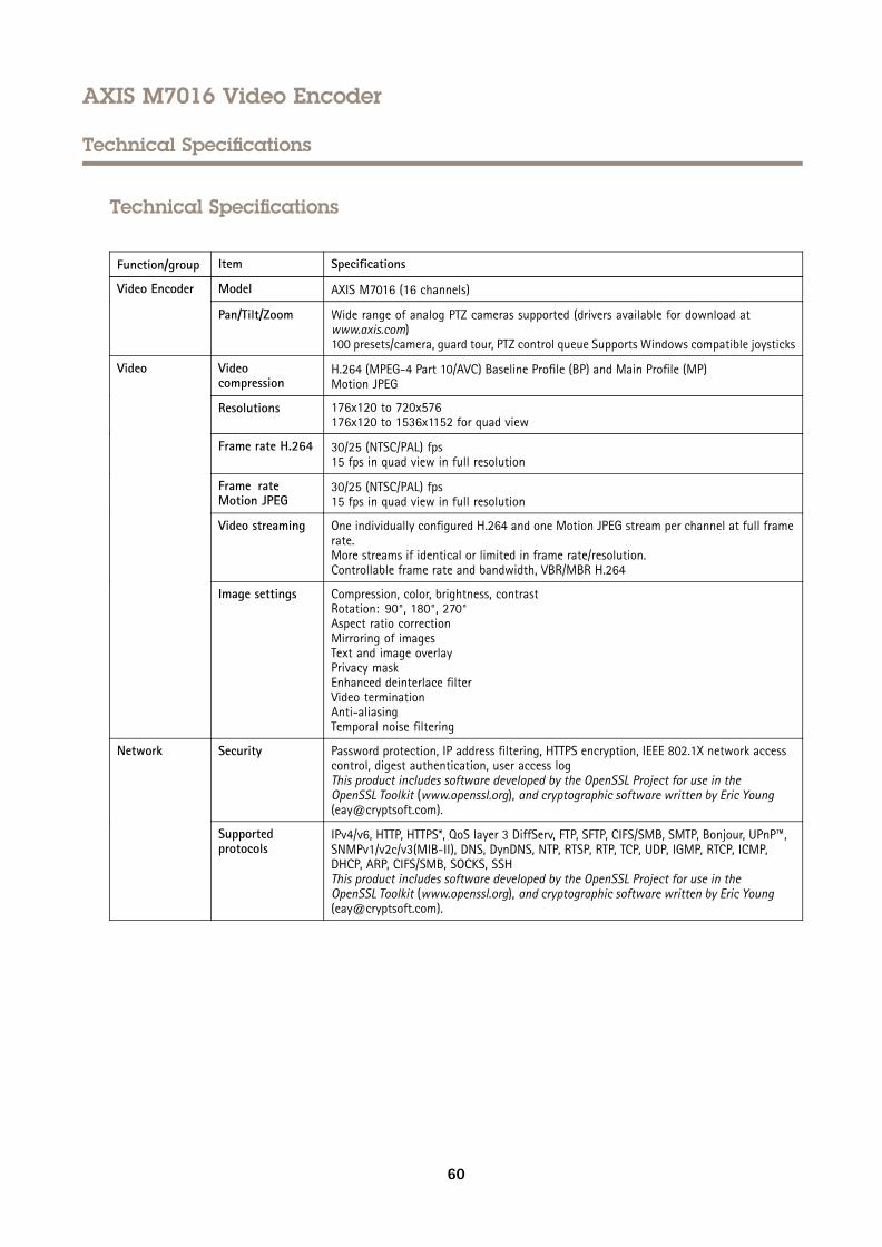
AXIS M7016 Video Encoder
Technical Specifications
Technical Specifications
Function/group Item Specifications
Model AXIS M7016 (16 channels)Video Encoder
Pan/Tilt/Zoom Wide range of analog PTZ cameras supported (drivers available for download atwww.axis.com)100 presets/camera, guard tour, PTZ control queue Supports Windows compatible joysticks
Videocompression
H.264 (MPEG-4 Part 10/AVC) Baseline Profile (BP) and Main Profile (MP)Motion JPEG
Resolutions 176x120 to 720x576176x120 to 1536x1152 for quad view
Frame rate H.264 30/25 (NTSC/PAL) fps15 fps in quad view in full resolution
Frame rateMotion JPEG
30/25 (NTSC/PAL) fps15 fps in quad view in full resolution
Video streaming One individually configured H.264 and one Motion JPEG stream per channel at full framerate.More streams if identical or limited in frame rate/resolution.Controllable frame rate and bandwidth, VBR/MBR H.264
Video
Image settings Compression, color, brightness, contrastRotation: 90°, 180°, 270°Aspect ratio correctionMirroring of imagesText and image overlayPrivacy maskEnhanced deinterlace filterVideo terminationAnti-aliasingTemporal noise filtering
Security Password protection, IP address filtering, HTTPS encryption, IEEE 802.1X network accesscontrol, digest authentication, user access logThis product includes software developed by the OpenSSL Project for use in theOpenSSL Toolkit (www.openssl.org), and cryptographic software written by Eric Young([email protected]).
Network
Supportedprotocols
IPv4/v6, HTTP, HTTPS*, QoS layer 3 DiffServ, FTP, SFTP, CIFS/SMB, SMTP, Bonjour, UPnP™,SNMPv1/v2c/v3(MIB-II), DNS, DynDNS, NTP, RTSP, RTP, TCP, UDP, IGMP, RTCP, ICMP,DHCP, ARP, CIFS/SMB, SOCKS, SSHThis product includes software developed by the OpenSSL Project for use in theOpenSSL Toolkit (www.openssl.org), and cryptographic software written by Eric Young([email protected]).
60
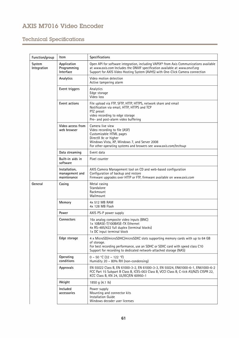
AXIS M7016 Video Encoder
Technical Specifications
Function/group Item Specifications
ApplicationProgrammingInterface
Open API for software integration, including VAPIX® from Axis Communications availableat www.axis.com Includes the ONVIF specification available at www.onvif.orgSupport for AXIS Video Hosting System (AVHS) with One-Click Camera connection
Analytics Video motion detectionActive tampering alarm
Event triggers AnalyticsEdge storageVideo loss
Event actions File upload via FTP, SFTP, HTTP, HTTPS, network share and emailNotification via email, HTTP, HTTPS and TCPPTZ presetvideo recording to edge storagePre- and post-alarm video buffering
Video access fromweb browser
Camera live viewVideo recording to file (ASF)Customizable HTML pagesDirectX 9c or higherWindows Vista, XP, Windows 7, and Server 2008For other operating systems and browers see www.axis.com/techsup
Data streaming Event data
Built-in aids insoftware
Pixel counter
SystemIntegration
Installation,management andmaintenance
AXIS Camera Management tool on CD and web-based configurationConfiguration of backup and restoreFirmware upgrades over HTTP or FTP, firmware available on www.axis.com
Casing Metal casingStandaloneRackmountWallmount
Memory 4x 512 MB RAM4x 128 MB Flash
Power AXIS PS-P power supply
Connectors 16x analog composite video inputs (BNC)1x 10BASE-T/100BASE-TX Ethernet4x RS-485/422 full duplex (terminal blocks)1x DC input terminal block
Edge storage 4 x MicroSD/microSDHC/microSDXC slots supporting memory cards with up to 64 GBof storage.For best recording performance, use an SDHC or SDXC card with speed class C10Support for recording to dedicated network-attached storage (NAS)
Operatingconditions
0 – 50 °C (32 – 122 °F)Humidity 20 – 80% RH (non-condensing)
Approvals EN 55022 Class B, EN 61000-3-2, EN 61000-3-3, EN 55024, EN61000-6-1, EN61000-6-2FCC Part 15 Subpart B Class B, ICES-003 Class B, VCCI Class B, C-tick AS/NZS CISPR 22,KCC Class B, KN 24, UL/IEC/EN 60950-1
Weight 1850 g (4.1 lb)
Includedaccessories
Power supplyMounting and connector kitsInstallation GuideWindows decoder user licenses
General
61
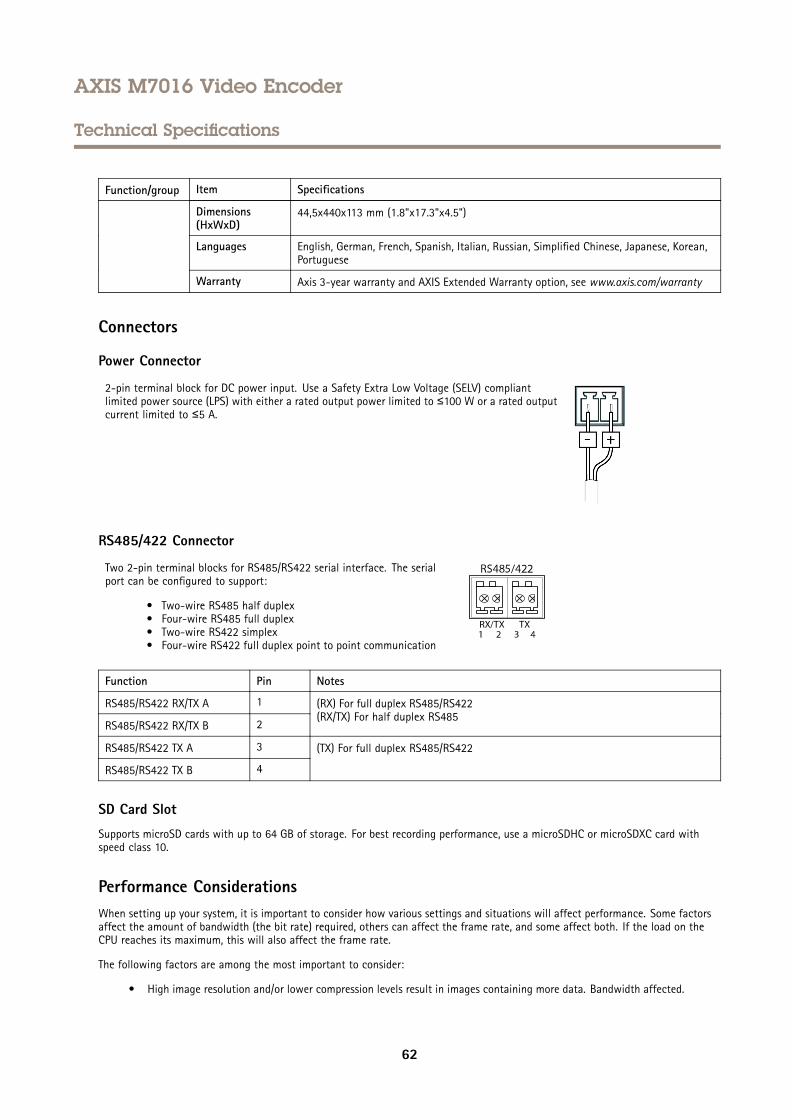
AXIS M7016 Video Encoder
Technical Specifications
Function/group Item Specifications
Dimensions(HxWxD)
44,5x440x113 mm (1.8"x17.3"x4.5")
Languages English, German, French, Spanish, Italian, Russian, Simplified Chinese, Japanese, Korean,Portuguese
Warranty Axis 3-year warranty and AXIS Extended Warranty option, see www.axis.com/warranty
Connectors
Power Connector
2-pin terminal block for DC power input. Use a Safety Extra Low Voltage (SELV) compliantlimited power source (LPS) with either a rated output power limited to ≤100 W or a rated outputcurrent limited to ≤5 A.
RS485/422 Connector
Two 2-pin terminal blocks for RS485/RS422 serial interface. The serialport can be configured to support:
• Two-wire RS485 half duplex• Four-wire RS485 full duplex• Two-wire RS422 simplex• Four-wire RS422 full duplex point to point communication
Function Pin Notes
RS485/RS422 RX/TX A 1
RS485/RS422 RX/TX B 2
(RX) For full duplex RS485/RS422(RX/TX) For half duplex RS485
RS485/RS422 TX A 3
RS485/RS422 TX B 4
(TX) For full duplex RS485/RS422
SD Card Slot
Supports microSD cards with up to 64 GB of storage. For best recording performance, use a microSDHC or microSDXC card withspeed class 10.
Performance ConsiderationsWhen setting up your system, it is important to consider how various settings and situations will affect performance. Some factorsaffect the amount of bandwidth (the bit rate) required, others can affect the frame rate, and some affect both. If the load on theCPU reaches its maximum, this will also affect the frame rate.
The following factors are among the most important to consider:
• High image resolution and/or lower compression levels result in images containing more data. Bandwidth affected.
62
AXIS M7016 Video Encoder
Technical Specifications
• Access by large numbers of Motion JPEG and/or unicast H.264 clients. Bandwidth affected.
• Simultaneous viewing of different streams (resolution, compression) by different clients. Effect on frame rate andbandwidth.
• Accessing Motion JPEG and H.264 video streams simultaneously. Frame rate and bandwidth affected.
• Heavy usage of event settings affect the product’s CPU load. Frame rate affected.
• Using HTTPS may reduce frame rate, in particular if streaming Motion JPEG.
• Heavy network utilization due to poor infrastructure. Bandwidth affected.
• Viewing on poorly performing client computers lowers perceived performance. Frame rate affected.
• Running multiple AXIS Camera Application Platform (ACAP) applications simultaneously may affect the frame rate andthe general performance.
63

User Manual Ver. M4.3AXIS M7016 Video Encoder Date: February 2016© Axis Communications AB, 2013 - 2016 Part No. 54592