Embed Size (px)
Citation preview
TECHNICAL REPORT RDCR 82-25
AN INVESTIGATION FOR MODELING JET PLUME EFFECTS0 ON MISSILE AERODYNAMICS
by:James H. HendersonNew Technology, Inc.
4811 Bradford Dr.Huntsville, AL 35806
for:
Systems Simulation and Development DirectorateUS Army Mingol Laboratory
US Army Misile Command
JULY 1982
iI
neadetcome jAreenalv, AIftbomrat 35009
Approved for public release; distribution unlimited.
SDTIC
S•::-.• 8 ELECTE!OCT 12, 1982
B
8 42115
SMI FOFRM 1M21•. 1 JUL 79 PREIMOUS EDITION IS OBSOLETE

UNC LAS S IFPIED ______
SECURITY CLASt'iCAT1Ot OF THIS PA'3.L (W?.-n r)',I Ir't'efd)
REPORT DOCUMENTATION PAGE _ READ INSTRUC TjOSBEF.ORE comPL:TINC, W)rm,,. REPORT NUIHER id. "O--- ACCEbSIONYO. J. RECIPIEN T°S C AT N-UMBR
RD-CR-82-2 54. TITLE (and Subtitle)
5. TYPE OF REPORT & PERIOD CO
An Investigation for Modeling Jet Plume Effects Technical Reportor, Missile Aerodynamics S. PERFORMING ORG. REPORTI NUMBERi
7. AUTHOR(m) S. CONTRACT OR GRNT NUIBER(.)
James H. HendersonNew Technology, Ina.. DAAH01-81-D-A02'4
9. PERFORMING ORGANIZATION Ni-,ME AND ADDRESi I0. PROGRAM ELEMENT. PROJECT, TASKAREA & WORK UNIT NUMBERS
Commander, US Army Missile CommandATTN: DRSMI-RDRedstone Arsenal, AL 35898 Work Order 4 003
II. CONTROLLING OFFICE NAME AND ADDROESS 12. REPORT DATE
Commander, US Army Missile Command July 82ATTN: DRSMI-RDK 13. NUMBER OF PAGES
Redstone Arsenal, AL 198q8 15014. MONITORING AGENCY NAME A ADDRESS(If different from Controlilng Office) IS. SECURITY CLASS. (of this report)
UNCLASSIFIED
1Sa, DECL ASSI FICATION/DOWNGRADINGSCHEDULE
16. DISTRIBUTION STATEMENT (of thia Report)
Approved for public release; distribution unlimited.
17. DISTRIBUTION STATEMENT (of the abstract entered In Block 20, If different from Report)
15. SUPPLEMENTARY NOTES
1I. KEY WORDS (Continue on reveres mide If necessary amd Identify by block number)
Plume modeling Base pressurePlume effects Plume effects simulationPlume interference
20. ABSTRACT rCovati,. rwovr.s m.i.d* Of n...smsry 0,1d id,•rtil, hy block number) Results of an investigationof concepts for modeling jet plume effects on missile aerodynamics tend to con-firm the concepts proposcl by Korst. Comparisons were made of afterbody pressuredistributions influenced by plumnes of the same shape but with different plumeMach numbers and with a solid plume. These comparisons indicate that increasingplume Mach number increases the Flume efi'ect on afterbody pressures with thiseffect becoining more proi'oic.. nod ,.:ith increasing frCoestream padCt number. Thesolid plume has thc groml tst effýe't on afterbody pressures with the effect
l1ncreIastilS co nside__bl_ o.lf 1.25 and higher.
DD , FA. 7 1473 EDITION OF I NOV o65 IS O.!OLE•L-L I INCI, ASSEI F I ED, .1. SECURI"Tr CLASSIFICATIONI OF THIS PAGE ("oen Dais Entered)

I
'I
I
iiBLANK PAGE
.*1 ___________
�1 -. --
- -

FOREWORD
The Army is currently ingagcd in a program to investigate air as a
medium for modeling propulsive jet plume interference effects on missile
aerodyhamics. Past research of plume effects on stability characteristics
has indicated the presence of a beneficial effect for free rockets. The
large stable transonic pitching moment usually associated with free rockets
is undesirable bocause of its effect on free rocket sensitivity to low level
winds during the boost phase of flight (Refs. I through 3). Plume interfer-
ence can be utilized to reduce stability (or destabilize the rocket) at
transonic, low supersonic speeds while maintaining stability at the desired
supersonic speeds. Other techniques for tailoring the variation of staticmargin with Mach number are discussed in Refs. 1 and 4. Several rocket sys-
tems being developed by the Army would benefit by this scheme of tailoring
the stability characteristics. However, at the present time the estimate of
plume effects on longitudinal stability cannot be made with the required
prccision.
Korst (Refs. 5 and 6) has proposed a modeling concept based on match-
ing the plume shape of the rocket (prototype) and the model. He imposes the
additional condition that jet plume surface Mach number be adjusted for the
model to account for the different specific heat ratio of the prototype. Amore detailed description of this modeling concept is presented in Ref. 7.
The purpose of this investigation is to experimentally contribute
to verifying the plume modeling concepts proposed by Korst and thereby improve
prediction of simulated plume effects. The investigation consisted of two
parts: (1) investigate thle plume effects of four separate nozzles withImatching plume shapes (when tested at the proper jet totail pressure ratio)
but with different plume surface Mach numbers, and (2) test nozzles modeled
to match data obtained from sled tests of a rocket configuration using a
ZAP motor. In addition, a solid plume matching the four air plumes was
tested. A norma) jet simulator similar to ones used in longitudinal sta-
bility tests was also tested. Wind tunnel tests were conducted using air

to supply the jets. The tests were conducted at the Calspan 8-ft transonic
wind tunnel at MIach numbers of 0.4 to 1.25 and at the NASA Langley Research
Center unitary wind tunnel at Mach numbers of 1.6 to 2.5, All tests were
made at an angle of attack of zero with the exception of two configurations
where data were obtained at an angle of attack of -5 degrees. Some prelimi-
nary results of the transonic tests are discussed in Ref. 8.
iv
' -- '. -. '- -

TABLE OF CONTENTS
Page
FOREWORD
LIST OF ILLUSTRATIONS vii
LIST OF TABLES ix
LIST OF SYMBOLS xi
I1.0 BACKGROUND
32.0 ANALYTICAL BACKGROUND
3.0 TEST CONCEPT 5
4.0 APPARATUS AND TESTS 9
4.1 Wind Tunnels 99
4.2 Model12
4.3 Tests
5.0 MODEL NOMENCLATURE 21
6.0 RESULTS AND DISCUSSION 23
7.0 CONCLUDING REMARKS 59
61
8.0 REFERENCES
APPENDIX A: DATA BASE 65
AOOession For ]NTIS GRA&I
DTIC TAB 0
Qxb UnannounceCO' 'rJustification
Dlstribution/ . .
Availability CodesAvail and/or
Dist SpecialE
. . . . . . . . . . . . . . . . ..

BANK PAGiEvi

LIST OF ILLUSTRATIONS
FigureP age
I Effect of Being Off Design Point cn Initial Plume Geometry 6
2 Installation Drawing of Model in the ralspan 8-ftTransonic Wind Tunnel 10
3 Photograph of the Model in the NASA Langley Research CenterUnitary Plan Wind Tunnel 11
4 Configuration Description 13
5 Comparison of Pressure Distributions of the Four Nozzlesat the Design Pressure Ratio and a Solid Plume 24
6 Comparison of Measured Nozzle Pressures with ComputedDistribution 34
7 Variation of Initial Plume Angle with Jet Total PressureRatio for ZAP Nozzle and ZAP Model tiozzle 38
8 Comparison of Jet-On and Jet-Off Base and Afterbody PressuresBetween the 6.12-in Sled Configuration and Wind Tunnel Con-figuration (1.76-3.95-.8) 39
9 Comparison of Wind Tunnel Model (1.76-3.95-.93) PressuresRelated to Sled P /Pb at M=1.65 to 7-in Diameter Sled BasePressures at M=1.63 41
10 Variation of Base Pressure with Thrust Coefficient for theFour Nozzles with Same "Design: Plume Shape 42
11 Effect of DN/DB on Variation of Base Pressure with ThrustCoefficient 49
12 Variation of Base Pressure with Radial Thrust Coefficientfor the Normal Jet Plume Effects 54
13 Ratio of Radial Thrust to Axial Thrust Required for the SamePlume Effect 57
vii
S... ,•. ,.• •;-••, • .. il•,•,• - A

BLANK PAGEviii

LIST oF TAB!.,ES
TablePage
I P 1 ime Geometry and Nozzle CharacterK stics 5
2 Orifier Locations (X/D Forward of b-o.e) 1
3 Model Nomenclature 21
IrI
ix t

II
* *1
BLANK PAGE
� �-�'-,
LIST OF SYMBOLS
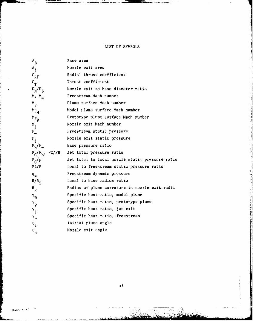
AB Base area
A. Nozzle exit area3
C Radial thrust coefficientRT
CT Thrust coefficient
DN/DB Nozzle exit to base diameter ratio
M, M Freestream Mach number
MF Plume surface Mach number
MFM Model plume surface Mach number
M Prototype plume surface Mach number
M. Nozzle exit Mach number
P Freestream static pressure
P. Nozzle exit static pressure
Pb/P. Base pressure ratio
Pc/P PC/PB Jet total pressure ratio
P c /p Jet total to local nozzle static pressure ratio
PL/P Local to freestream static pressure ratio
q• Freestream dynamic pressure
R/RB Local to base radius ratio
R Radius of plume curvature in nozzle exit radiiR
Ym Specific heat ratio, model plumeY p Specific heat ratio, prototype plume
yj Specific heat ratio, jet exit
.Y. Specific heat ratio, freestreamO. Initial plume angle0 Nozzle exit angle
n
xi

BLANK PPALExlii
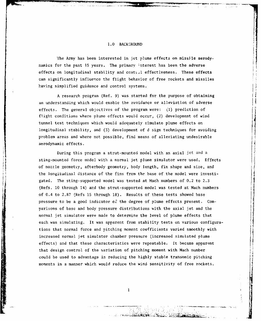
1.0 BACK03ROUND
The Army has been interested in jet plume effects on missile aerody-
namics for the past 15 years. The primary interest has been the adverse
effects on longitudinal stability and ccniti. effectiveness. These effects
can significantly influence the flight behavior of free rockets and missiles
having simplified guidance and control systems.
A research program (Ref. 9) was started for the purpose of obtaining
an understanding which would enable the avoidance or alleviation of adverse
effects. The general objectives of the program were: (1) prediction of
flight conditions where plume effects would occur, (2) development of wind4
tunnel test techniques which would adequately simulate plume effects on
longitudinal stability, and (3) development of d sign techniques for avoiding
problem areas and where not possible, find means of alleviating undesirable
aerodynamic effects.
During this program a strut-mounted model with an axial jet and a
sting-mounted force model with a normal jet plume simulator were used. Effects
of nozzle greometry, afterbody geometry, body length, fin shape and size, and 1A
the longitudinal distance of the fins from the base of the model were investi-gated. The sting-supported model was tested at Mach numbers of 0.2 to 2.3
(Refs. 10 through 14) ard the strut-supported model was tested at Mach numbers
of 0.4 to 2.87 (Refs 1$ through 18). Results of these tests showed basej
pressure to be a good indicator of the degree of plume effects present. Coin-
parisons of base and body pressure distributions with the axial jet and the
normal jet simulator were made to determine the level of plume effects that
each was simulating. It was apparent from stability tests on various configura-
tions that normal force and pitching moment coefficients varied smoothly with
increased normal jet simulator chamber pressure (increased simulated plume
effects) and that these characteristics were repeatable. It became apparent
that design control of the variation of pitching moment with Mach number
could be used to advantage in reducing the highly stable transonic pitchingV
moments in a manner which would reduce the wind sensitivity of free rockets.

The severity of plume effects vary with missile acceleration. PlIume
effects are first noticed at subsonic-transonic speeds for moderate accelera-
tions and extend to higher Mach numbers as acceleration is increased. For a
constant acceleration the region of plume influence on the missile recedes
with increasing Mach number with only a small region at the base influencd
at the highest Mach number. By placing fins forward of the base (on the order
of 0.5 to 2.0 missile diameters) it is possible f'or the fins to become fully
effective at the desired supersonic Mach number while the body surface near
the base is still under the influence of the plume. By proper sizing and
SIlocation of the fins it is possible to have some design control over tile
pitching moment characteristics.
In addition to wind tunnel tests, a series of sled tests were made with
a ZAP rocket firing during the sled run in an attempt to verify plume effects
during flight (Refs. 19 and 20). It was planned to make both force and pres-
sure measurements during the tests. The force tests were unsuccessful but
sufficient pressure data were obtained to verify the presence of jet plume
effects. Most of the pressurc data were influenced by sled interferenceIbut some interference free data were obtained for Mach numbers of about 1.4
to 1 .EC.At the present time, tailoring the pitching moment for free rockets I
cannot be done as precisely as required for the optimum reduction in wind
errors during boost. For improved tailoring it is necessary to know how well
the actual rocket plume is being simulated in the wind tuiiael. A comparison
can be made between the normal jet simulator and various cold air nozzle axial
jets. The remaining problem is knowing the difference between the effects of
cold air axial jet (or other unheated fluid) and the actual rocket plume.
2

2.0 ANAIYTICAL BACKGROUND
The analysis of axially symmetric supersonic flow near the center of
expansion as developed by Johannesen and Meyer (Ref. 21) has been used by
Korst (Refs. 5 and 6) to form the basis for plume modeling involving gases
with dissimilar specific heat ratios. This analysis allows the rapid calcula-
tion of plume shapes which are approximated by a circular arc defined by the
initial slope of the jet boundary (0.) and the radius of curvature (RR). The
first requirement of Korst's modeling technique is the geometric matching of
the plume to be modeled (prototype) with the model plume. The assumption of
locally conical source flow near the exit of the nozzle leads to a direct
correspondence of nozzle shapes producing the same plume geometry. Thus,
modeling requirements are reduced to determining ofr nozzle exit Mach number
(NI) and nozzle exit angle (0n).1 n
Korst sets another condition in addition to the geometric matching
of the plumnes: the proper modeling of the closure condition for the wake is
necessary. Korst suggests for consideration a choice of four specifying con-
ditions for the wake closure of the modeling law in Ref. S. These conditions
are matching the wake recompression of the Chapman-Korst flow model, match-
ing momentum at the corresponding plume boundaries, matching mass flux at
the corresponding plume boundaries, and matching the supersonic inviscid
streamline deflection-pressure rise relation on the basis of local lineari-
zation. In Ref. 7, Korst and x, p recommend the final specifying condition
which requires that
2 2YM 1 YP MI"M 1
2 112 2 112(1(M -1) (M -1)
M P
where Y is specific heat ratio, MF is the plume surface Mach number, and
the subscripts M and P represent the model and prototype, respectively.
3

Although the circular arc appr(ximatioi, starts to diverge from the
actual plume shape after about one nozz.e radius, the analysis of Ref. 21
provides the second-order initial conditions necessary for the calculation of
the plume boundary by the method of characteristics (Ref. 22). Thus, it is
possible to obtain accurate plume matching well beyond the valiidity of the
circular arc approximation. (See the plume comparisons of Ref. 5.)
A
I
k-VA!
:-• _:.... ............ ..... ....... .... .... ........ . .... . .. • .• . o•.,,!,.l•.i :i • •:•'.•'N•.-.. . . . .. . . . . . . . . . . . . . . . . . . ...... ..... . .1

3.0 TEST CONCEPT
The purpcse of the tests was to verify the plume modeling concepts
proposed by Korst. By using the simplified method for rapid determination of
plume shape, it was possible to determinc families of nozzles which produce
identical plume shapes when operating at the proper jet total pressure (Pc/Pb).
Since the plume surface Mach number (MF,) would differ for each nozzle, the
validity of wake closure ccaditions could be investigated with the use of only
one jet gas. With the specific heat ratio constant, the direct effect of plume
surface Mach number on afterbody flow could be investigated. An investigation
to verify the plume modeling concept using dissimilar propellant gases is now
in progress in Sweden (Ref. 23). 4The exit geometry of four nozzles were determined which would give
matching plume shapes at the desired (design& prssure ratio. An initial plume
angle of 42 deg was selected to insure a plume having characteristics which
would cause flow interference. The matching plume geometry and the character-
istics of the four nozzles are given in Table 1.
'Fable 1 Plume Geometry and Nozzle Characteristics
DESIGN M Rn Pc/Pb F R
1.7 9.1 39.6 3.05 3.734
2.0 13.6 55.14 3.274 3.739
2.4 19.35 82.44 3.555 3.739
2.7 23.3 108.2 3.750 3.734
The plumes of the four nozzles match only at the proper value of
chamber to base pressure ratio. With a change of chamber pressure from the
"design point," the radius of curvature changes slightly for matching values of
initial plume angle (Fig. 1). Comparisons of plumes with matching initial
angles several degrees off of the design value should be valid.
S

48r
46I
44 -
41- DESIGN POINT
S40
38
36 2.7-23.3-.8
1.7-9.1-.8
2.0-13.6-.82.4-f9.35-.8
343.0 3.2 3.4 3.6 3.8 4.0
PLUME RADIUS OF CURVATURE, RR NOZZLE RADII
Fig. 1 Effect of Being Off Design Point on Initial Plume Geometry

In additiun to the four nozzles a solid plume was investigated. The
plume shape was determined by the method of c.aracteristics and matched the
plume shape produced by the four nozzles at the "design point." By comparing
the effects of the solid plume on afterHody pressue's With the effects of the
four nozzles, a measure of plume flcxibil Iy may be determined. The solid
plume represents a plume with infinite st iftness (Ref. 8).
The second part of the investigation of plume modeling techniques
consisted of an attempt to model the plume effects of the ZAP rocket motor.
The Army Missile Command has recently been involved in sled tests where ZAP
motors were fired. The sled was accelerated to low supersonic Mach numberswith the rocket being ignited at various sled velocities. The sled test con-
figuration had an igive nose and was strut mounted on the sled with a boundary
layer plate between the sled and the model. The first series of tests used
the same rocket diameter" as the ZAP vehicle '1).1'7 in). The sccond series of
tests had diameters of 7 in. Both afterbody and base pressure measurements
were made. An unsuccessful attempt was made to also measure aerodynamic forces
on the 7-in model. A complete description of the sled test is given in
Refs. 19 and 20.
In order to model the zAP plume effects it was necessary to determine
nozzle exit conditions. The Solid Propellant Equilibrium Chemistry Program
utilized for this purpose gave an exit Mach number of 2.53 and a ratio of
specific heats at a nozzle exit of 1.235. ZAP nozzle has an exit cone angle
of 10.36 deg. The measurable thrust obtained di, ring the sled tests varied
between about 10,000 to 27,000 lb. For plume modeling purposes a thrust of
about 19,000 lb was chosen. At this thrust the ZAP (prototype) has a plume
Mach number (MF:) of 3.35, an initial plIIime angle of 32.31 deg, an initial
plume radius of curvature of 5.427, and a chambcr to base pressure ratio of
83.1. Using the streamline deflection closure condition [Eq. (1)], a plume
Mach number for the ZAP model was determined to be 2.906. It was determined
that the model (air) nozzle would htrve an exit Mach number of 1.76 and an
exit angle of 3.95 deg, and would match the prototype plume when the chamber
to base pressui, ratio was 39.1. Model nozzles were fabricated to match
both the 6.13-in and 7.0-in diameter sled vehicles having nozzle to base
diameter rat ios (1N/1) of 0.8 and 0.93, res.,,-ttively.
N - t-3'< .

Since the nozzles of this investigation have short divergent sections,
the supersonic flow can be significantly affected by throat geometry. A pro-
gram was written by Korst (Ref. 24) where throat curvature could be deter-
mined which would give flow conditions approaching the nozzle lip that were
close to ideal conical source flow. This program uses transonic flow field
solutions near the throat, suggested by a combination of the Oswoattitch-
Rothstein (Ref. 25) and Sauer (Ref. 26) analysis followed by the method ofcharacteristics.
A normal jet plume effects simulator has been utilized by the Army
Missile Command to obtain stability characteristics on several missile and
free rocket configurations (e.g., Refs. 10 through 14). The normal jet
simulator is advantagrcous because of the comparatively low mass flow required
to simulate jet effects and because of the absence of unintended interference
with the model flow field. A normal jet simulator was tested so that its
relationship with the modeled plumes could be investigated.
8

4.0 APPARATUS AND TESTS
4.1 WIND TUNNELS
Test. were conducted in the Calspan Corporation 8-ft transonic
wind tunnel and the NASA Langley Research Center unitary plan facility.
The Calspan 8-ft transonic wind tunnel is a continuous flow, variable
density facility. The maximum clear tunnel Mach number is 1.30. The tunnel
may be operated at stagnation pressures from 0.10 to 3.25 atmospheres to provide
a variation of Reynolds number independent of Mach number. A detailed descrip-
tion of the tunnel is presented in Ref. 27.
The supersonic tests were conducted in the low-speed circuit of the
unitary plan wind tunnel. This facility is a continuous circuit wind tunnel
with a 4 x 4 ft test section capable of opý.La~ing at stagnation pressures up
to 60 psia and at Mach numbers of 1.50 to 2.87. A detailed description of
the facility is given in Ref. 28.
4.2 MODEL
The model was a 2.5-in diameter body of revolution having a four-
caliber tangent ogive nose followt by a cylinder. The model was 32.5-in
long with the aft 8.55 in of the cylinder consisting of interchangeable
afterbodies. A strut support was used to mount the model to the wind tunnel
suppert system. The strut was ducted internally to supply high pressure air
to the model chamber. Pressure instrumentation was also routed through the
strut.
A drawing of the model installed in the Calspan 8-ft transonic wind
tunnel is shown in Fig. 2. A photograph of the model in the Langley Research
Center unitary plan facility is shown in Fig. 3. In the Langley facility the
model was arranged in the test section so that the support strut was 30 deg
above the horizontal. The sting support system was offset to the right side
of the model center line.
L1
9=

VI 4Ih.2
0 z
Ck. 0 C
-j 14C
C- E
5z 12AJ~
L..
I- 4A
4-
100

-�__-
-- -
b
-
0)C
t0�
I-
VC
a.>9
5-
C IZD5-.�1)4-)
C0)
(2
-c5-C-)
en0)CrU,>9
0)
)Th4j�S .Y
a
09
�0)
-c
.9 7�.'Ia&*� '*�%i' 4.. -
4-C
4 0
5-.(a0�0
4-)
.4
0
Cr
r x' .� �ye
�0�V
I
.'----�.*-

Seven afterbodies were built by Calspaa for the present tests. On
each afterbody 10 external static pressure 6rifices were installed in a single
row 180 deg from the strut. A manifold of three base pressure orifices wasS~installed in the upper quadrant of each afterbody.
Four of the afterbodies incorporated nozzles designed to produce
congruent plumes when operating a$ the proper jet pressure ratio (Fig. 1).
Two additional afterbodies contained nozzles designed to model the Plume
effects of the ZAP rocket on both the 6.12- and 7.0-in diameter sled configura-
tions. The afterbodies had nozzle exit to base diameter ratios (DN/DB) of
0.8 except the nozzle modeling the 7.0-in diameter sled configurations. This
afterbody had a ba~e diameter ratio of 0.93. Each nozzle had four static
piessure orifices on the nozzle wall opposite the support strut.
The final aftarbody was built to hold th. solid plume and the normal
jet simulator. This afterbody had the same distribution of external pressure
orifices as the nozzle afterbodies. The solid plume was designed to match thesize and shape of the plumes of the four nozzles previously mentioned. Thenormal jet simulator consists of 24 sonic nozzles arranged circumferentially
in two rows with a common air chamber. Air is supplied to the chamber through
Lhe model. The combined exit area of the 24 nozzles represented 6% of tie model
base area. (The geometry of the normal jet simulator is proportional to the
normal jet simulators used on sting supported model tests. in these tests the
simulator was mounted on the sting and air was supplied from the rear.)
Details of the various afterbodies are presented in Fig. 4. Orifice
locations in terms of model diameters from the base are presented in Table 2.
Due to the lack of test time, the internal orifices on the two ZAIP model
nozzies were not connected.
4.3 TESTS
The modul was tested at zero angle of attack except for a few runs Hat transonic speeds where the model was pitched to -5 deg angle of attack.
During a run Mach number was held constant and jet chamber total pressure
was varied up to about 600 psia. Where matching plumes were desired, the
P /Pb value was set on or near the "design point" with additional data points
close to the design point. No transition grit was applied to the model.
12

t6L 0 -D N J
A~ zo
0CL-.
C2040.1
ujz u-j -4 4.i
CA C)LU M. C- 0
LU .- 4 U
az N
'I-.
J[0U NN
0 0 I
u. <
La.
13
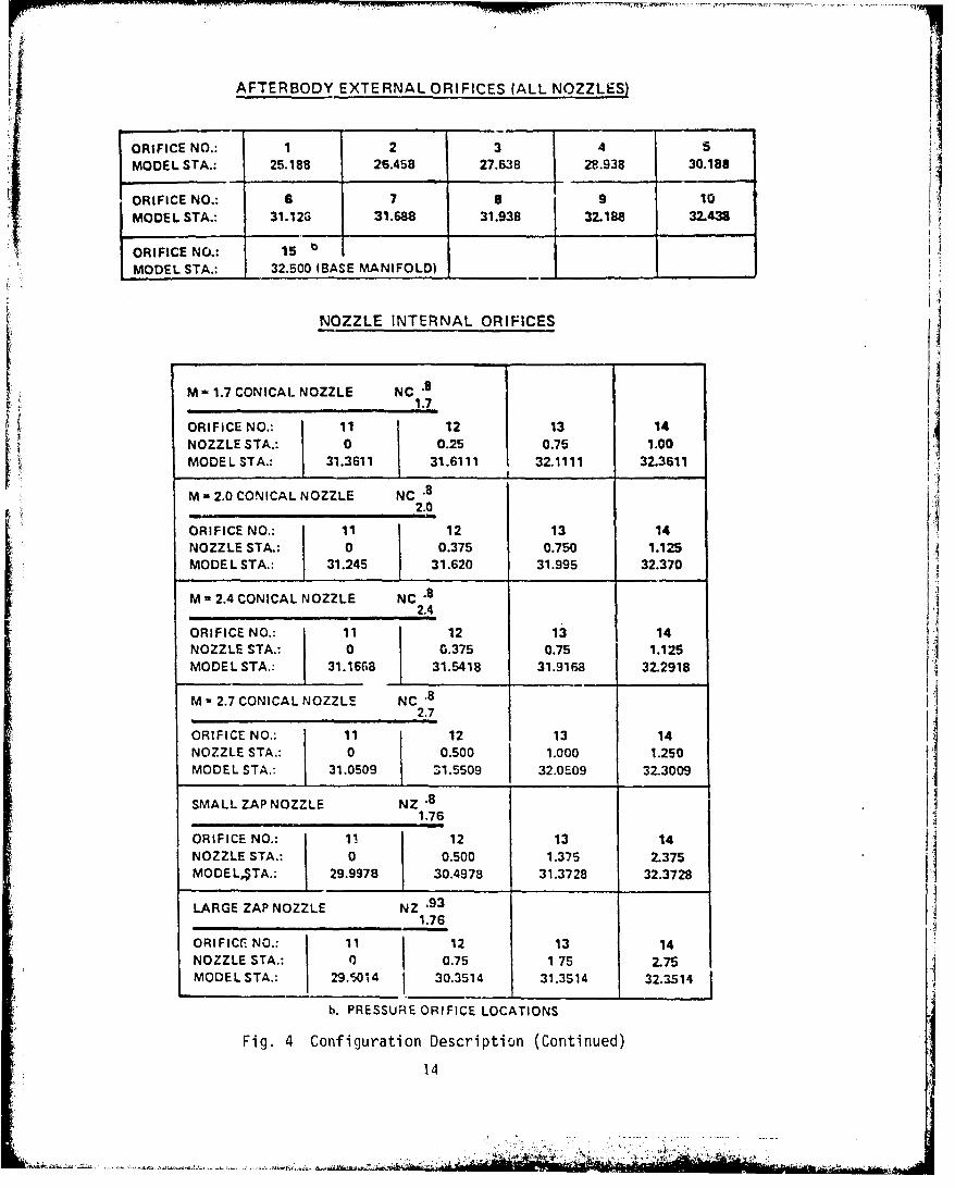
AFTERBODY EXTERNAL ORIFICES (ALL NOZZLES)
ORIFICE NO.: 1 2 3 4 5MODEL STA.: 25.188 26.458 27.638 28.938 30.188
ORIFICE NO.: 6 7 8 9 10MODEL STA.: 31.12G 31.688 31.938 32.188 32.43=
ORIFICE NO.: 15 MMODEL STA.: 32.500 (BASE MANIFOLD)
NOZZLE INTERNAL ORIFICES
M .1.7 CONICAL NOZZLE NC .8
1.7
ORIFICE NO.: 11 12 13 14NOZZLE STA.: 0 0.25 0.75 1.00MODEL STA.: 31.3611 31.6111 32.1111 32.3611
M- 2.0 CONICAL NOZZLE NC .82.0
ORIFICE NO.: 11 12 13 14NOZZLE STA.: 0 0.375 0.750 1.125MODEL STA.: 31.245 31.620 31.995 32.370
M 2.4 CONICAL NOZZLE NC.82.4
ORIFICE No.: 11 12 13 14NOZZLE STA.: 0 0.375 0.75 1.125MODEL STA.: 31.1668 31.5418 31.916a 32.2918
M - 2.7 CONICAL NOZZLE NC .82.7
ORIFICE NO.: 11 12 13 14NOZZLE STA.: 0 0.500 1.000 1.250MODEL STA.: 31.0509 31.5509 32.0E09 32.3009
SMALL ZAP NOZZLE NZ .81.76
ORIFICE NO.: 11 12 13 14NOZZLE STA.: 0 0.500 1.375 2.375MODE LSTA.: 29.9978 30.4978 31.3728 32.3728
LARGE ZAP NOZZLE NZ .931.76
ORIFICE. NO.: 11 12 13 14NOZZLE STA.: 0 0.75 1 75 2.75MODEL STA.: 29.5014 30.3514 31.3514 32.3514
b. PRESSURE ORIFICE LOCATIONS
Fig. 4 Configuration Description (Continued)
14

NC .3 NC .8 NC .8 NC .81.7 2.0 2.4 2.7
d = 2.0000 d - 2.0000 d 2,000 d , 2.000
d/D - 0.80 d/D - 0.80 d/D 0.80 d/D - 0.80i - 7.50 15 0. 150 9 ' 15°
0e = 9.100 Ge 13'60" Ge 19.35° 0 = 23.300
r r x
-.9560 .96000 .1.3681 .96000
-.4889 .8985(0) .1.0061 ,9600U .4914 .72510
•.4510 .8939 . .4944 .82290 .4537 .7169
-.,4137 .8898 • .4535 .8159 .4177 .7093
-.3768 .8860 .4133 .8096 .3823 .7025
-.3401 .8826 .3736 .8039 .3476 .6963 -1.5954 .9600}
-.3035 .8735 . .3341 .7987 .3129 .6907 .5210 .67210-.2666 .8767 .2943 .7941 - .2785 .6857 .4361 6537 H-.2299 .8743 - .2547 .7901 . .2435 .6812 .3596 .6396
-.1922 .8722 - .2138 .7865 . ,2089 .6773 -. 2867 .6284
-.1282 .8695 1425 .1817 - .1724 6738 .2158 .6199.0641 .8679 - .0713 .7788 .08w' .F681 .1414 .6134
0 .86740 0 .7778@ 0 i620 0 6o5.0641 .8679 .0713 .7788 .0862 .6681 .1414 6134
.1282 .8695 .1425 .7817 .1724 .6738 .2158 .6199
.1922 .8722 2138 .7865 .2089 .6773 .2867 .6284
.229-9 .8743 2547 .7901 .2435 .6812 .3596 .6396
.2660 .8767 2943 .794.1 .2785 .6857 .4361 .6537
.3035 .8795 .3341 .7987 .3129 .6907 .5210 .6721
.3401 .8826 .3736 .8039 .3476 .6963 .6201 .6968
.3768 .8860 .4133 .8096 .3823 .7025 .7445 .7325
.4137 .8898 .4535 .8159 .4177 .7093 .9118 .7872
.4510 .8939 4944 .8229 4527 .7169 1.1533 .8771
.4889 .8985 51 .8355 .4914 .7251 1.4)38 .9848@
.5276 .9035 .6596 .8564 .52S2 .7342 1.4491 1.0000
.5673 .9090 .7125 .86880 .5696 .7444
.6084 .9152 1.2550 1.0000(D 6121 .7558
.6408 A9202 40 6577 .7687
1.1389 1 00000 .7071 .7835
.7608 .8004
.8194 .8199
8620 [email protected] 1.0000(D)
(D NOZZLE ENTRANCE
Q UPSTREAM TANGENT POINT
@ THROAT
@ DOWNSTREAM TANGENT POINT
( NOZZLE EXIT
NOZZLE IS CCNICAL BETWEEN @ AND ( ,AND BETWEEN @ AND (D AT HALF ANGLESOF 0, AND 9e, RESPECTIVELY.
c. CONICAL NOZZLE COORDINATES
Fig. 4 Configuration Description (Continued)
15

s.- , , •fl
NZ '8 NZ 9 3
1.76 1.76
d - 2.0000 d - 2.3168diD - .80 d/D - .9267
e. so E H9i = ° i--5
ee - 3.95' = 395
x X r
-1.6018 .9 6 00 0
- .4588 .86000
- .4088 .8575 -1.2483 11U000
* .3609 .8553 .4181 .99080 2
.3145 .8535 .3643 .9887
- .2690 .8519 • .3116 .9868
t. .2243 .8506 - .2598 .9854
• .1800 .8496 - .2085 .9842
0 .84780 0 .98190
.1800 .8496 .2085 .9842
.2243 .8506 .2598 .9854
.2690 .8519 .3116 .9868
.3145 .8535 .3643 .9887
.2609 .8553 .4181 .9908
.4088 .R575 .4736 .9933
.4588 .8600 .5315 .9962
.5115 .8629 .5925 .9996
.5378 .8665 .6577 1.0037
.5998 .8686® .6948 1.0062(
2.5022 1.00000 2.8986 1.158®(D
O NOZZLE ENTRANCE
(D UPSTREAM TANGENT POINT
0J THROAT
o DOWNSTREAM TANGENT POINT
®• NOZZLE EXIT
NOTE: INLET SECTION AHEAD OF NZ .93 NOZZLE IS EXPANDED TO 2.200 IN. DiA. -SEE SKETCH1.76
d. ZAP NOZZLE COORDINATES
Fig. 4 Configuration Description (Continued)
16

~w j0 C1i
Do to L NC 0 - -n a) 00LoL) 0
Jw 0 0
U- w
0iN
+c 0w- z
o4
4-)
0 -
(A-cc uf
17w W

Table 2 Orifice Locations (X/D Forward of Base)
BASE AND AFTIRBODY ORIFICh: ILOCATIONS
X/D(CALIBERS
FORWARDNo. OF BASh)
15 0.000 (BASE)1) 0.025
9 0. 1258 0.2257 0. 3250 0.551 H5 0.925
4 1.4253 1.945
2 .417I1 2.92S
NOZZLE ORIFICE LOCATIONS
1.76-3.95-.8 1.76-3.95-.8 1.7-9.1-.8
TAP X/D R/RB X/D R/RB X/D R/RB
14 0.051 0.7955 0.059 0.9279 0.056 0.782713 0.451 0.7417 0.459 0.8822 0.156 0.750112 0.801 0.6898 0.859 0.8081 0.356 0.700511 1.001 0.6782 1.159 0.7855 0.456 0.6939
TAP 2.0-13.6-.8 2.4-19.35-.8 2.7-23.3-.8 414 0.052 0.7780 0.083 0.7436 0.080 0.732813 0.202 0.7024 0.233 0.6375 0.180 0.655012 0.352 0.6433 0.383 0.5610 0.380 0.533811 0.502 0.6222 0.533 0.5330 0.580 0.4868
18

The transonic test was run at constanL mass operating conditions of
1/3 atmosphere wind-of" pi.'ssure. Mach number varied between 0.4 and 1.25
and Reynolds number varied between about 0.8 to 2.0 million/ft. Several data
points were obtained with zero tunnel velocity. A complete description of
the transonic tests is given in Rof. 29. Mr. (.F, Reid was the Project
Manager for tests in the Calspan Corporation Transonic Wind Tunnel.
The supersonic tests were performed -o.er a Mach number range from
1.6 to 2.5. Only one run was made at a Mach number of 1.6 due to the plume
choking the tunnel flow. A Mach nu~nber of 1.65 was subsequently tested as
the minimum NI, ch number. The tunnel stagnation pressure varied from about21080 lb/ft to about 1600 lb/ft. The Reynolds number was held constant at
2.0 million/ft. The dewpoint was maintained sufficiently low to insure
negligible condensation effects. Mr. Peter F. Covell was the Project Manager
for the tests in the Langley Research Center unitary plan facility.
19
I

I
I
II
I
I
IIIII
BLANK P�E20
a
�2..

5.0 MODEl. NOMENCLATURE
Where data from nozzle configurations are compared the more des ....
nomenclatire used in previous Army Missile Command reports will be used. l,
nomenclature is designated by Mj-0N-DN/DB where Mj represents jet exit Mach
number, 0N represents nozzle exit angle ani 1,X/DB represents the nozzle exit
to model base diameter ratio. For example, the large ZAP nozzle is designated
as 1.76-3.95-.93. Results of the present tests have L-en stored in the Army
Missile Command Aerodynamic Analyzer System data base. This system was used
to make plots of the basic data. A 5- or 6-character designation was used to
identify configurations and are used on the plots of the basic data in
Appendix A. A different model designation was used by Calspan. Figures 2
through 4 were reprinted from Ref. 29 and the Calspan designation is used.
A comparison of the three designations are given in Table 3.
Table 3 Model Nome:.,Jla.ure
PRESENT MICOM CALSPANREPORT AAS
M j- - DN/DB DATA BASE
.81.7-9.1-.8 BlAZ43 NC 1.7
1.7
.82.0-13.6-.8 BIAZ44 NC 2.0
.82.4-19.35-.8 BIAZ45 NC 2.4
.82.7-23.3-.8 BIAZ46 NC 22.7
.81.76-3.95-.8 BlAZ41 NZ 11.76
931.76-3.95-.93 BIAZ42 NZ 1.761.76
NORMAL JET BlAJ2 S1
SOLID PLUME B1AS3 S2
21
- I

I
I,
I
I
I
I
I
BLANK PAGE22
- j-*
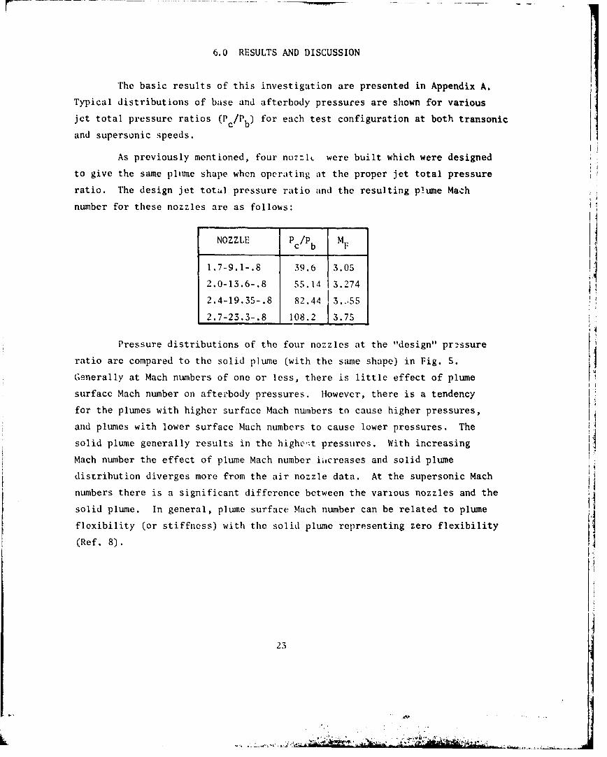
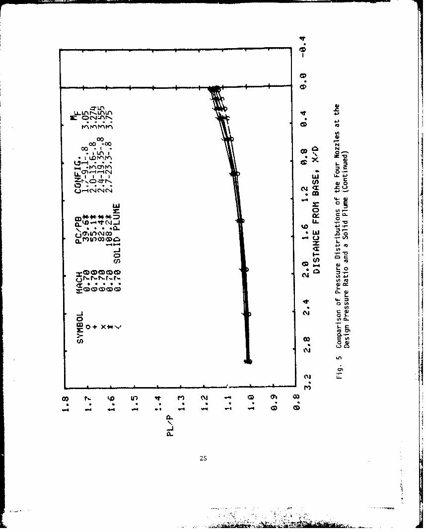
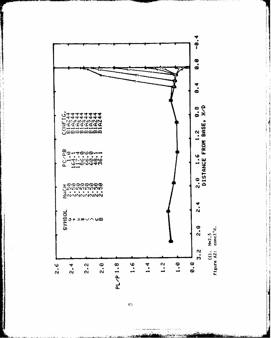
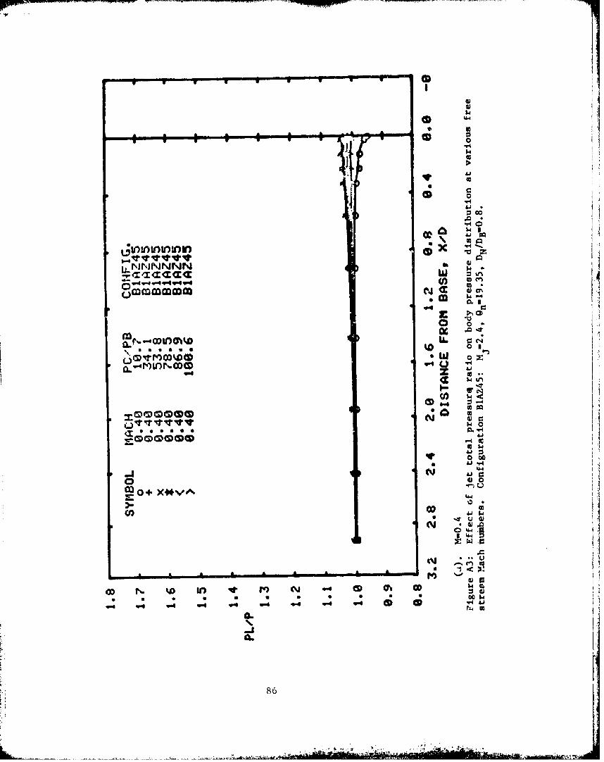
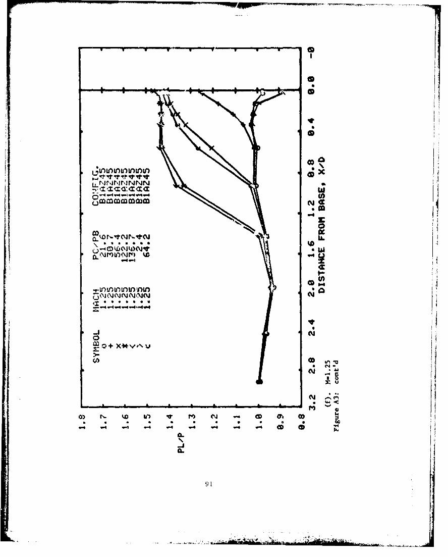
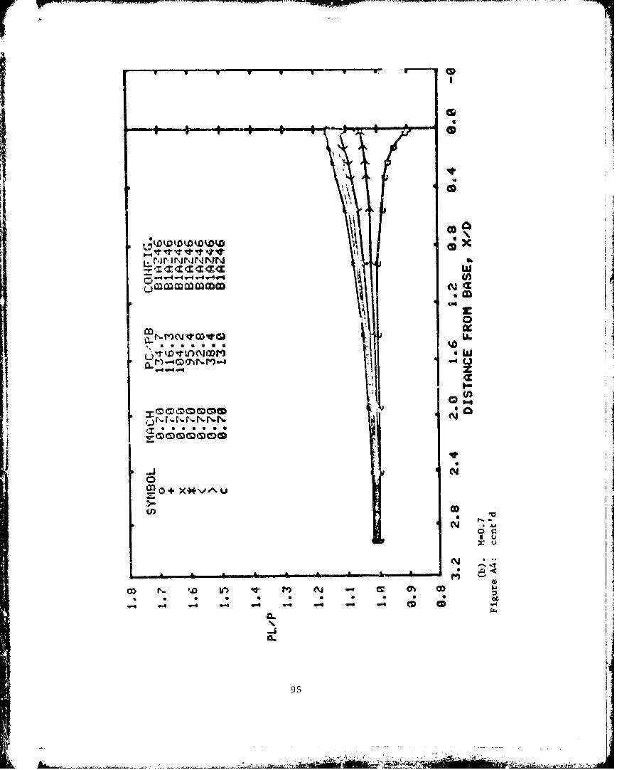
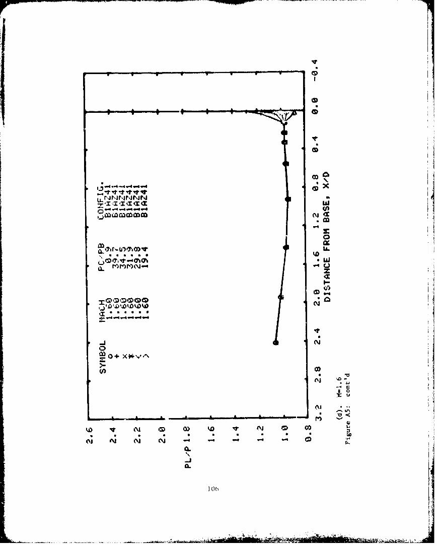
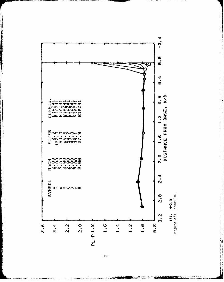
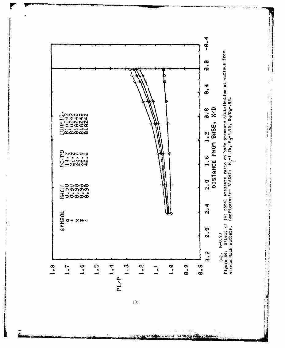
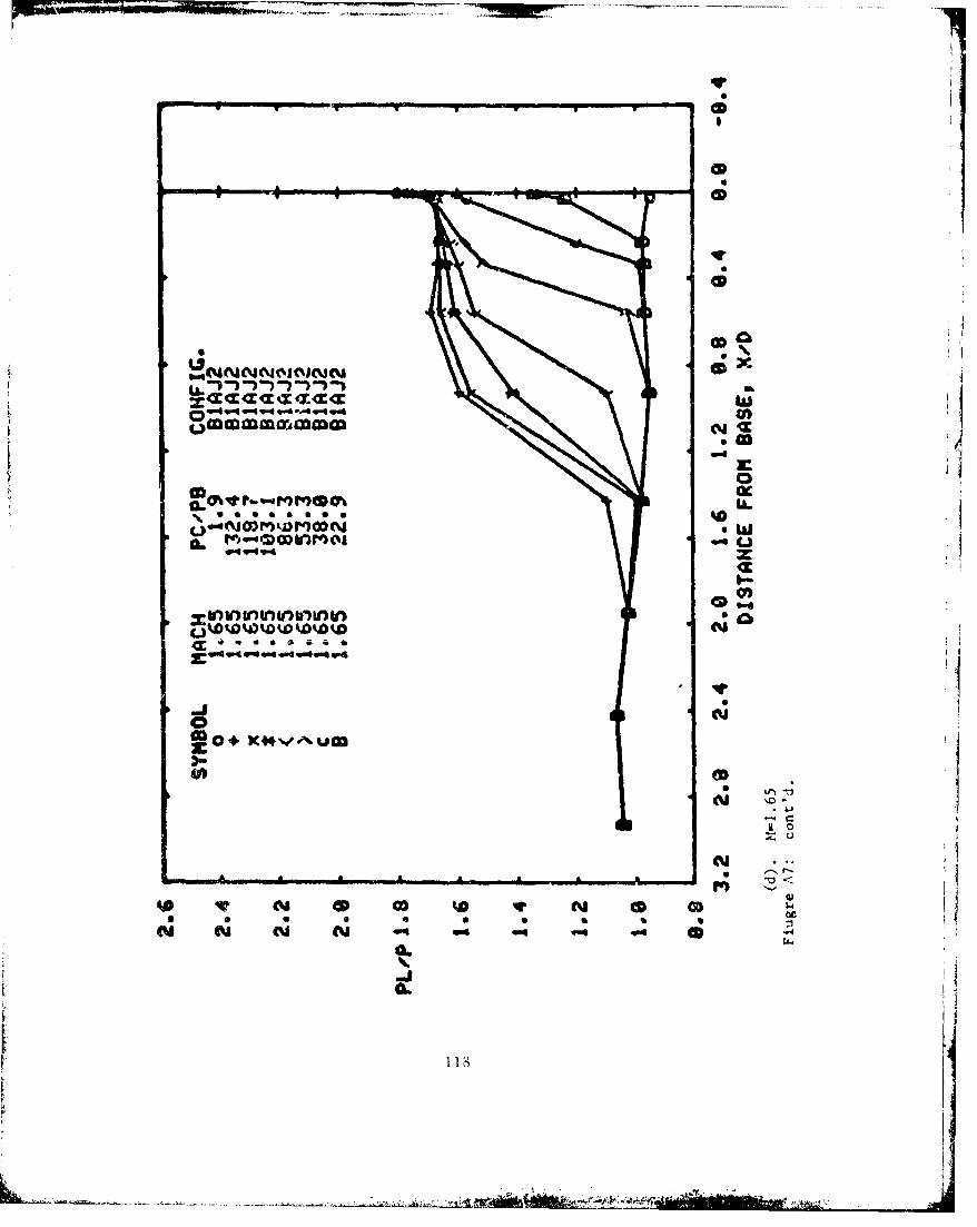
6.0 RESULTS AND DISCUSSION
The basic results of this investigation are presented in Appendix A.
Typical distributions of base and afterbody pressures are shown for various
jet total pressure ratios (P c/Pb) for each test configuration at both transonic
and supersonic speeds.
As previously mentioned, four nozzlL were built which were designed
to give the same pliume shape when operating at the proper jet total pressure
ratio. The design jet total pressure ratio and the resulting plume Mach
number for these nozzles are as follows:
NOZZLE Pc/Pb M F
1.7-9.1-.8 39.6 3.05
2.0-13.6-.8 55.14 3.274
2.4-19.35-.8 82.44 3..,55
2.7-23.3-.8 108.2 13.75
Pressure distributions of the four nozzles at the "design" pr-essure
ratio are compared to the solid plume (with the same shape) in Fig. S.
Generally at Mach numbers of one or less, there is little effect of plume
surface Mach number on afterbody pressures. However, there is a tendency
for the plumes with higher surface Mach numbers to cause higher pressures,
and plumes with lower surface Mach numbers to cause lower pressures. The
solid plume generally results in the highe,;t pressures. With increasing
Mach number the effect of plume Mach number ii,creases and solid plume
distribution diverges more from the air nozzle data. At the supersonic Mach
numbers there is a significant difference between the various nozzles and the
solid plume. In general, plume surface Mach number can be related to plume
flexibility (or stiffness) with the solid plume representing zero flexibility
(Ref. 8).
23
L .. A.- -

00 IA
00 00 (
Ný 0.: t
LU
w ~-4-- 0)_ ~ oE
- 4J
9- -L 1
4- 14* ~ ~~ S S S S
- C.
tu0
4*~ CL
LL Ln~ r-~.% Ln 4J
00 -00N00 -1w(
lit r_ LL4-0---0
kj -4 Tr ("L _.j I. . "0a a a *a~ '.D4J. 1 .
SW .0
V-4 4-) M
I--
ti
0G E/~0
Lfl
lot1
0~ ~. ~ ) N ~25

T '7.
00 -00
00.II 0 0 N' 0
* .M -4 -l 4J--, I ~I I I r_
... I II in 44.0
U, 07 11; ct~ .0 Wa-a.~~~"- M 'A I iU j'I
cj) (A
0 (A
i0D03 S- c
0 (ODi0.0
-LA
06.
26
000
- v) a) w
r- . C- (NC Uj400
(A
00 -00r N_
a)IM 0 0 )o
0----
0~ 0
o ~0
N p LO)
C; 4
s'L
271

000
00 N 000 -I - - 0
N-N SY % -
U-i(C'NC-CN M 4-0
wr
LA 4-)
0 C
(A CL
k\J
0) L6'.A
CLI
27I

-- -n -- n %
oi
00
0 0o0 aN
K% s-i.--.
IIw (1 0,(L." 04 CNC'C'
0- Ew*
% vi0 Q
v- 0-4 (
0) (1 0S-
N l U) S...co 0 + X p[
0T-t0~~~~~~~ (ADI) 7~ i -
28
..... ....

000
oco
U-,
ca 0
LNujN
in* w 4
vt 61 -*-
0 4
Il-
M 5-
Ciii
QD0 + X
29'

qF r'v' 't~- V
ICI000
00 -00N00- -1 3O
01- -~ -f N - C I I
-~L -- ". q4 .
wI 0..
IM i-
It~~~- (0 )I N 0 0
w4i w-4 -P- J v-J v-4.4 v4 . "4
0 0
-JS0...
30Q

U- II1II-. EVNA n
Imi
00 N
U'% Q C
M OCNU-IVN r_
'1 ~ a 0)IN
00 N
C 0 -00 a -
(M ~N CMI Of J4SC'~~Z 4- =
0 4A
IA
o'Ii) Ai 'm I" %A
-CJ
A-.

oooS
000 N)
-r I I (
0)
IMX
U..=
~OIq C *W Lr-V)
lL'~~~~4- I(0 I i~.
.,- -0
o 4-
a S S S..
~0a)
0- "OjHV CD D to r ED.
0) 03)
Ji

There is some doubt of the precision of plume geometry at the "design"
conditions. The nozzle wall pressure distributions are compared to computed
distributions in Fig. 6. From extrapolation of the measured values it appears
that the nozzle designed for an exit Mach number of 2.7 has an exit Mach numbernearer to 2.6 and the nozzle designed for an nxit Mach numbier of 1.7 is nearer
to 1.8. The other two nozzles appear to I~u -lose to the design value. Even
with the reduced precision, it is expected that the general conclusions stated
will remain valid. An analysis of the transonic data by Nenni (Ref. 30)
indicates that tIhe "design" plume shapes from SChlijern photographs compareH
well with computed plume shapes.
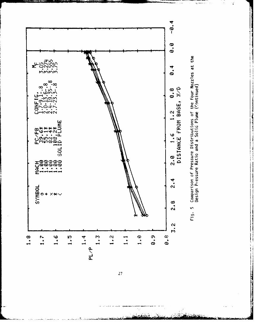
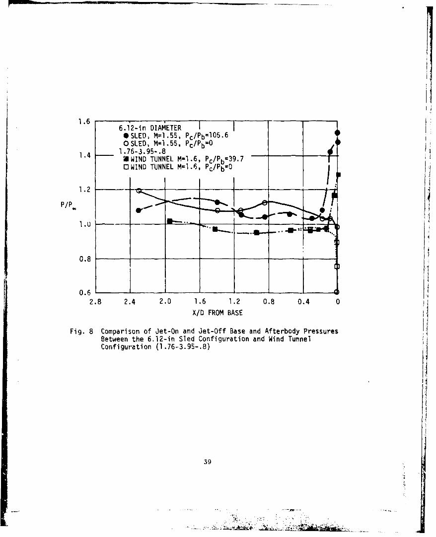
A review of the sled data was made for possible comparisons with the
wind tunnel results. It appears that the sled data a't conditions matching
transonic tunnel measurements was affected by interference from the sled toI
such an extent as to make it questionabl~e. When t~sts were run at the unitary
tunnel, blockage resulting from the plume size voided planned tests at a Mach
number of l.S. A run wa.. made with the smaller ZAP model nozzle (1.76-3.95-.8)
at a Mach number of 1.6 and blockage occurred at values of P c /Pb > 40. The
remaining ZAP configuration (1.76-3.95-.93) was tested at a minimum Mach number
for the test of l.6E. j
No exact comparisons were available between the sled data and wind
tunnel data. However some off-design comparison can be made where the two
Mach numbers are slightly different. For thrust levels where the prototypeI
(ZAP) is not exactly modeled, the comparison should still be valid (Ref. 7).
Where initial plume angles are matched there is only a small discrepancy in
initial plume radius of curvature. The variation of P /P with initial plumec bangle for both the prototype (y=1.235) and the model (y=1.4) is shown in Fig.
7. Comparison between the 6.12-in sled data (M=1.56, P c /Pb=105 ) and the
model (M=1.6, P c/Pb= 40 ) is shown in Fig. 8. From the preceding figure it
is apparent the plumes nearly match. The data in Fig. 8 compare both the
jet-on and jet-off pressure distributions. For this case the sled plumo
effects are greater than the model plume effects.
33

6'
5
£• 4MEASURED
COMPUTED
2
0I
0.5 0.4 .0.3 0.2 0.1 0X/D FROM BASE
a. NOZZLE 1.7-9.1-.8
Fig. 6 Comparison of Measured Nozzle Pressures withComputed Distribution
34

8
6COMPUTED
s.u4
2
0 I I I I0.5 0.4 0.3 0.2 0.1 0
X/D FROM BASE
b. NOZZLE 2.0-13.6-.8
Fig. 6 Comparison of Measured Nozzle Pressures withComputed Distribution (Continued)
35
L kub k.1

16
12
]2 • A
10
U8
~ MEASURED
6
COMPUTED
4
2
O _ II II0.6 U. 0.4 0.3 0.2 0.1 0
X/D FROM BASE
c. NOZZLE 2.4-19.35-.8
Fig. 6 Comparison of Measured Nozzle Pressures withComputed Distribution (Continued)
36
.r ,i

20 i
16
12i
MEASURED LCOMPUTED
8
I4
0.6 0.5 0.4 0.3 0.2 0.1 0
X/D FROM BASE
d . NOZZLE 2.7-23.3-.8IFig. 6 Comparison of Measured Nozzle Pressures with
Computed Distribution (Continued)
3 7

C)cv C) C) CID:co~~ C) CDC
0:)
12.
CC'
CLFC) 0
F-x
Va
I0
-c
_ _a
LU -%- r.4
4-I0
C~
CDC- D ) DCD ,CCh co fl, ri L -ctm Ca
'd/odw
38 .~
1.66.12-in DIAMETER
*SLED, M=1.55, Pc/Pb- 1 0 5 .6OSLED, M1 .55, Pc/PbO
1.4 1.76-3.95-.8 _(1UWIND TUNNEL M=1.6, PC/Pb= 39 . 7
OWIND TUNNEL M=1.6, Pc/Pb=O
P/P.0
0.8
0.6 I2.8 2.4 2.0 1.6 1.2 0.8 0.4 0
X/D FROM BASE
Fig. 8 Comparison of Jet-On and Jet-Off Base and Afterbody PressuresBetween the 6.12-in Sled Configuration and Wind TunnelConfiguration (1.76-3.95-.8) v
39
~ .,,

There appears to be more matching conditions for the carlier 6-inZAP configuration and the modeled nozzle (1.76-3.95-.8). Unfortunately, theorifice distribution on the sled was designed to measure pressures at trausonic
speeds and consequently few orifices are located near the base of' the model
where the plume effects are restricted to a small area at supersonic speeds.
The variation of base and afterbody pressures on the wind tunnel configuration
fl.76-3.95-.8) with --led jet total pressure ratio at a Mach numbe" of 1.65 is
shown in Fig. 9. The wind tunnel Pc/Pb was related to the sled Pc/P1b by using
Fig. 7. Also shown in Fig. 9 is the variation of base pressure an the 7-in
sled at a Mach number of 1.63. The base pressure was the only usable data
during this sled run. The only other orifice in the area influenced by the
plume appeared to be plugged. However, there appears to be a fairly good
match between sled and wind tunnel base pressures.
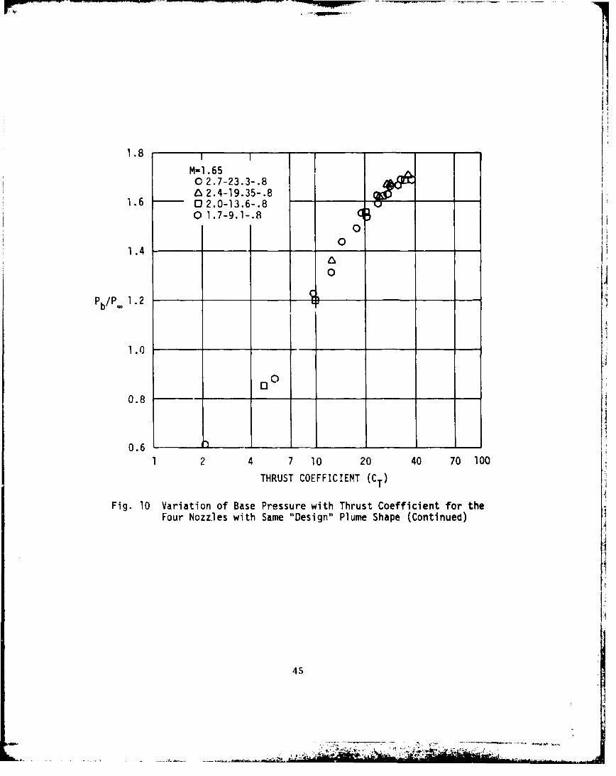
Brazzel (Ref. 31) used thrust coefficient (CT) as a parameter for
correlating sustainer level jet effects on base pressure. Althoigh jet-oni
base pressure is influenced by many variables, the use of CT allowed thei
analysis of experimental data in a manner where adequate design information
could be obtained. Thrust coefficient is given by 2
2YjpjAjMj + A. (pj -pC)CT pA.M + A.(Thrust
CT = - - - (2)1/2y. p. ABM2 q AB(
where the subscripts j and - represent the jet and freestream, respectively.
For simulated sustainer thrust levals where the base is aspirated by
the jet, the use of CT appears to account for all the variables except jet
Mach number (assuming the use of air or similar gas for the jet). At the
thrust levels high enough for the plume to influence the afterbody, there is
the added effect of nozzle exit angle and nozzle exit to base diameter ratio.
Since four of the nozzles of the present tests were built to give the
same "design" plume shape, it appeared reasonable that CT should te a goo.
parameter to correlate base pressure. Shown in Fig. 10 is a comparison of
the variation of Pb/p. with CT for these nozzles for Mach numbers o? 0.9 to 2.5.
40

V -' ~-~ 711- - ,
04
UCie
4-&__ oC4
-M V)
'C71
000
cnn
_ _~~ * _ n
c*)e LAV) CD 04 MLC) L0j VitSr Cý C;C3 C) 41
a.L.
41-- .-

1.4
M=0. 901.7-9.1-.8. 2.0-13.61-.8
1.3 12.4-19.35-.8 A
0 2.7-23.3-.8
1.2 1Q
0
1.0 i
0
0.9
0.81 2 4 7 10 20 40 70 100
THRUST COEFFICIENT (CT)
Fig. 10 Variation of Base Pressure with Thrist Coefficient for theFour Nozzles with Same "Design" D'ume Shape
42

..... MM.M
1.4 M-I .01@
01.7-9.1-.8 IA6 2.0-13.61-.8 0
1.3 0 2.4-19.33-.802.7-23.3-.8 0
1.2
1.1 0
P b/P .
1.0
0.9I. L
0.8
0
0.7 _ _
1 2 4 7 10 20 40 70 100
THRUST COEFFICIENT (CT)
Fig. 10 Variation of Base Pressure with Thrust Coefficient for theFour Nozzles with Same "Design" Plume Shape (Continued)
43
.A

1.5
M-1l .250 1.7-9.1-.8& 2.0-13.61-.8 o0_
1.4 0 2.4-19.35-.80 2.7-23.3-.8
1.3 - 0
0
1.2
Pb/P. 1.1
1.00
0.9o
0.8
0
0.7 -
1 2 4 7 10 20 40 70 100
THRUST COEFFICIENT (CT)
Fig. 10 Variation of Base Pressure with Thrust Coefficient for theFour Nozzles with Same "Design" Plume Shape (Continued)
44
1.8 I-I
M-1 .650 2.7-23.3-.8& 2.4-19.35-.8
1.6 0 2.0-13.6-.8 -
0 1.7-9.1-.80
01.4
0
1.0
0.8
0.61 2 4 7 10 20 40 70 100
THRUST COEFFICIENT (CT)
Fig. 10 Variation of Base Pressure with Thrust Coefficient for theFour Nozzles with Same "Design" Plume Shape (Continued)
45

2.0
M-2.002.7-23.3-.8
1.8 -- 2.4-19.35-.8 -
0 2.0-13.0-.801.7-9.1-.8 ]
0
1.4
0
Ib P/P.0
1.2 -
o4
1.0
0
0.8
00.6
2 4 7 10 20 40 70 100
THRUST COEFFICIENT (CT)
Fig. 10 Variation of Base Pressure with Thrust Coefficient for theFour Nozzles with Same "Design" Plume Shape (Continue.)
46

2.4
M-2.50 2.7-23.3-.8 (2.2 0 2.0-13.6-.8 -"
0 1.7-9.1-.8
2.00
1.8 - _ _
1.60
Pb/P. 0
1.4u
1.2 (5I0
1.0 -0
0.8 0
0.61 2 4 7 10 20 40 70 100
THRUST COEFFICIENT (CT)
Fig. 10 Variation of Base Pressure with Thrust Coefficient for theFour Nozzles with Same "D=,ign" Plume Shape (Continued)
47
.......... " ........•................•_

It appears that a fairly good correlation in obtained for all of the freestreamMach numbers shown. The approximate value of 1b/p for the "design" plumes
Jb
may be obtained from Fig. 5.
The correlation obtained in Fig. 10 suggests a slight change in
approach of modeling plume effects on aerodynamics. For high acceleration
tactical missiles and free rockets, the exit Mach number is usually between
about 2.3 to 2.7. Using the Korst modeling technique the model no:zle exit
Mach number will vary from less than two to nearly sonic. When the exit Mach
number is close to sonic, the nozzle will be difficult to fabricate with
precision required to give an • ri &xit Mach number. However, a higher
exit Mach number and higher exit a.;". nozzle designed to match the plume shape
of the model nozzle could be ,•tilized. For example, a model nozzle having
an exit Mach number of 1.7 and an exit angle of 4 deg could be replaced by a
nozzle having an exit Mach number of 2.5 and an exit angle of 15 deg. The
plume Mach number for the Mj = 2.5 nozzle would be higher than that of the
model nozzle resulting in plume with a higher stiffness factor, but this fact
would tend to account for the effects of afterburning (Ref. 32).
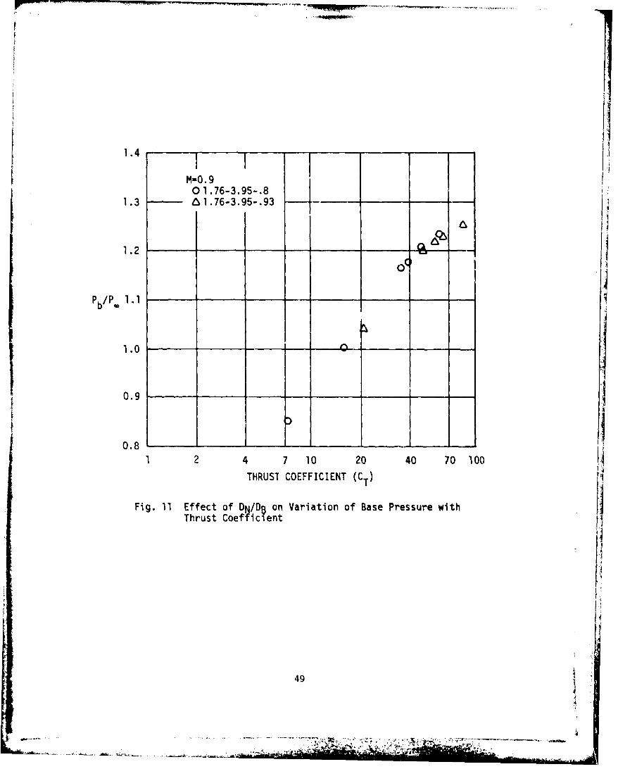
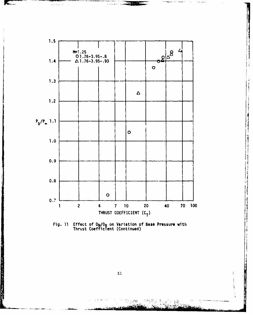
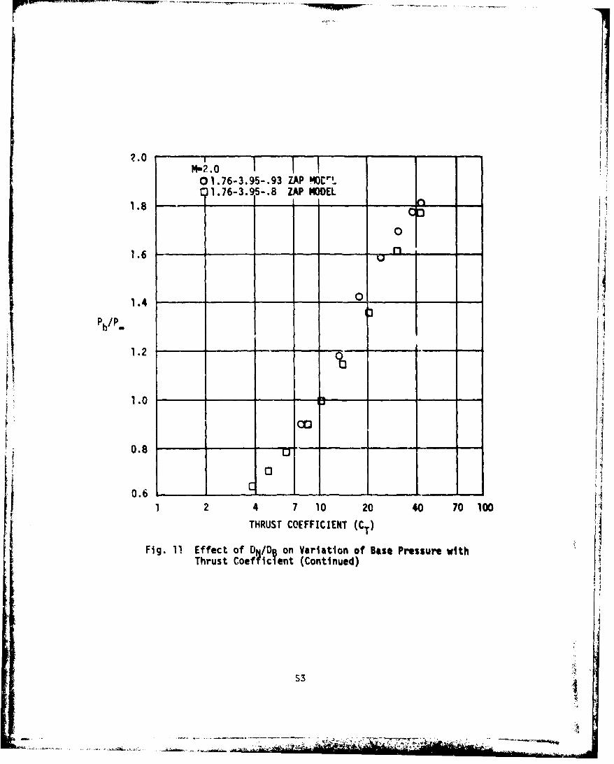
The variation of base pressure with CT for the two ZAP configurations
is shown in Fig. 11. Base pressure is not correlated by CT qs well as for the
nozzles in Fig. 10.
The variation of base pressure with radial thrust coefficient (CRT) for
the normal jet plume effects simulator is presented in Fig. 12. Radial thrust
coefficient is given by
radial thrustq. Aref
where radial thrust is the total thrust from the 24 nozzles on the simulator.
The normal jet simulator, which is used on sting-mounted force models, tends
to simulate the radial component of momentum of an axial plume. By comparing
the variation of base pressure with CT from Figs. 10 and 11, and variation of
base pressure with C in Fig. 12, an indication can be obtained of the amountRT
of radial thrust required to simulate the same plume effect: as the axial jet.
48
1.4
M-0 .90 1.76-3.95-.8
1.3 6 1.76-3.95-.93 - (
1.2
0o
Pbpo1.1
1.0 _
0.9 1
0.8 ____ 1 ____1
1 2 4 7 10 20 40 70 100
THRUST COEFFICIENT (C
Fig. 11 Effect of DN/DB on Variation of Base Pressure withThrust Coefficient
49
"e--" W1 'r

1.4
0 1.76-3.95-.8 41.3 -- O1.76-3.95-.93 _ __
0
1.2
1.1
PbVP 0
1.0
0.9
0.8 -
0.7 d_ _
1 2 4 7 10 20 40 70 100THRUST COEFFICIENT (CT)
Fig. 11 Effect of DI/D on Variation of Base Pressure withThrust Coefficient (Continued)
so'
i, 50
1.5
M-1i .251.4 A01.76-3.95-.9-8___
01.76-3.95-.93
0
1.3
1.2
P b/P" 1.1
0
1.0
0.9
00.8 -
1 2 4 7 10 20 40 70 100
THRUST COEFFICIENT (CT)
Fig. 11 Effect of DN/DB on Variation of Base Pressure withThrust Coefficient (Continued)
• ,.• ..- ••L• '•' P•- •mJ • ... • L•; ••..• •'r • •P ?•'•:51

PI'1.75o1.76-3.95-.93
1.8 01.76-3.95-.8
1.6 _00
1.4
Pb/
1.2
1.0 0 -i
0.8
0.61 2 4 1 10 20 40 70 100
THRUST COEFFICIENT (CT)
Fig. 11 Effect of DN-/DR on Variation of Base Pressure withThrust Coefficient (Continued)
52
HW2.0
0 1.76-3.95-.93 ZAP MOCr"1:)1.76-3.915-.8 ZAP MODEL
1.8 - - .... n____ __
•~ 3•
0
1.6 . -
1.4 0
P b/P.
1.2
0,0
0.8 U
0.6 c ___
1 7 4 7 10 20 40 70 100THRUST COEFFICIENT (CT)
Fig. 11 Effect of DN/DB on Variation of Base Pressure withThrust Coefficient (Continued)
5
..... _, ,,•• ' • i.; .:' .•'L -•,V,:;• '• •; i :. ,

1.7
0 M-0.9
1.I1.01.6 -Ma•.25
-,--PLATEAU PRESSURE
1.5
3
1.4
AA1.3
0
00
0*0
c 1.2
1.0
0.9
0.8
0.7 ....1 2 4' 710 20 40 70 100
RADIAL THRUST COEFFICIENT (CRT)
Fig. 12 Variation of Base Pressure with Radial Thrust Coefficientfor the Normal Jet Plume Effects
54
If

2.60 M-2.5
OM-2-00 02M.2.0 I.OM-1.65 I - _ _
--- PLATEAU PRESSURE 0-
2.2 -
2.0 , -,
0 0) 0 0
1.8
ci
1.4
1.2 - _ _ _ _ __ _
1.0 - __ _ -
0.8
0.6 0.4 0.7 1 2 4 7 10 20
RADIAL THRUST COEFFICIENT (CRT)
Fig. 12 Variation af Base Pressure with Radial Thrust Coefficientfor the Normal Jet Plume Effefts (Continued)
55

The fraction of radial to axial thrust required to simulate about the same
plume effects is shown in Fig. 13 for the two families of nozzles in the
present investigation.
At high values of C RT and for the supersonic Mach numbers in Fig. 12(b),
the base pressures induced by the normal jet simulator exceed the plateau
pressure established by Zukoski (Ref. 33). If thrusts at this level are to be
simulated, better results would probably be obtained with the simulator moved
further aft.
i5

0.16 , _
1.7-9.1-.82.0-13.61-.80 2.4-I19.35-.8
0.12 12.7-23.3-.80.76-3.95-.93
CRTCT 0.08 76-3.95-.8
0.04
00 0.4 0.8 1.2 1.6 2.0 2.4 2.8
MACH NUMBER (M)
Fig. 13 Ratio of Radial Thrust to Axial Thrust Required for theSame Plume Effect
57
- - .-. -~i. * .

BLANK ~~
58
7.0 CONCLUDING REMARKS
An investigation of concepts for modeling jet plume effects on missile
aerodynamics has been made. The experimental results tend to verify the modeling
concepts proposed by Korst. Comparisons ,%ore made of afterbody pressure
distributions under the influence of different air plumes having the same shape
but with different surface Mach numbers. The comparisons indicate that
increasing plume Mach number generally increases the plume effect on afterbody
pressures with this effect becoming more pronounced with increasing Mach number.
A solid plume with -:he same shape as the air plumes has the greatest effect on
afterbody pressures with the effect increasing considerably at freestream Mach
numbers of 1.25 and higher.
The shape of afterbody pressure distributions under the influence of
plume effects simulated by the normal jet simulato, compared favorably with
the di. tributions under the influence of axial jets. The ratio of normal
to axial thrusts, CRT/CT, required to simulate the same level of effects
varies with both freestream Mach number and axial jet nozzle geometry.
An attempt was made to compare sled tests of the ZAP rocket with an
air nozzle modeled by Korst's concept. No exact match of test conditions was
available, but the few cases where comparisons were possible tended to confirm
the validity of the modeling concept.
I r
59
=-,. :•,• -A ,x-l ,
" "•- .......... " - ................ .. .. ... ... ,-- • .•..... ""- • - " ¢•r :• ) ::• 1 . .. <'i• ") •'t , .... • ",• - " 4

~.-~~ --.- BLANK- _
60I

8.0 REFERENCES
1. Pettis, W. Jr., "Effects on Normal Force of Streamwise Gaps Between theBody and Fins of a Missile Configuration," Master of Science Thesis,Department of Aerospace Engineering, Mechanical Engineering and EngineeringMechanics, University of Alabama, University, Alabama, 1971.
2. "Design of Aerodyrnamically Stabilized tree Rockets," EngineeringDesign Handbook, U.S. Army Material C'mm,,,d, AMCP 706-280, 1968.
3. Davis, L., Jr., J.W. Follin, Jr. and L. Blitzer, The Exterior Ballisticsof Rockets, D. Van Nostrand Company, Inc., Princeton, N. J., 1958.
4. Dahlke, C.W. and W. Pettis, "Normal Force Effectiveness of Several FinPlanforms with Streamwise Gaps at Mach Numbers of 0.8 to 5.0," TechnicalReport RD-TR.-70-8, U.S. Army Missile Command, Redstone Arsenal, Alabama,Aprii 1970.
5. Korst, H.H., "Approximate Determination of Jet Contours Near the Exit ofAxially Symmetrical Nozzles as a Basis for Plume Modeling," U.S. ArmyMissile Command, Redstone Arsenal, Alabama, Report No. TR-RD-72-14,August 1972.
6. Korst, H.Ht., "An Analysis of Jet Plume ModAling by Dissimilar PropellantGases," Proceedings, 43rd Semi-Annual Meeting, Supersonic Tunnel Associa-tion, Pasadena, California, 2-3 April 1975.
7. Korst, H.H. and R.A. Deep, "Modeling of Plume Induced Problems in MissileAerodynamics," Proceedings, 17th Annual Aerospace Sciences Meeting (AIAA),New Orleans, Los Angeles, 15-17 January 1979.
8. Korst, H.H., R.A., White, et al, "The Simulation and Modeling of Jet Plumesin Wind Tunnel Facilities," Proceedings, llth Annual Aerodynamic TestingConference (AIAA), Colorado Springs, Colorado, 18-20 March 1980,Pages 80-430.
9. Deep, R.A., J.H. Henderson, and C.E. Brazzel, "Thrust Effects on MissileAerodynamics," U.S. Army Missile Command, Redstone Arsenal, Alabama, ReportNo. RD-TR-71-9, May 1971.
10. tiender3on, J.1., "Transonic Wind Tunnel Investigation of Thrust Effects onthe Longitudinal Stability Characteristics of Several Body-Fin Configurations(Sting-Mounted Model with Normal-Jet Plume Simulator)," U.S. Army MissileCommand, Redstone Arsenal, Alabama, Technical Report RD-75-14,"31 December 1974.
11. Henderson, J.H., "An Investigation of Jet Plume Effects on the Stabilit!
Characteristics of a Body of Revolution in Conjunction with Fins ofVarious Geometry and Longitudinal Positions at Transonic Speeds (Sting-Mounted Model with Normal Jet Plume Simulator)," U.S. Army Missile Command,Redstone Arsenal, Alabama, Technical Report RD-75-37, 12 June 1975.
12. Henderson, J.II., "Investigation of Jet Plume Effects on the LongitudinalStabitity Characteristics of a Body of Revolution with Various Fin Co'-figurations at Mach Numbers from 0.2 to 2.3 (Normal Jet Simulator),"U.S. Army Missile Command, Redstone Arsenal, Alabama, lachnical ReportRD-76-22., February 1976.
61
S• •,:~ • , ,o - *.. .. - -

REFERENCES (Contii,.ed)
13. Dahlke, W., "An Investigation of Flow and Stability Characteristics fora Body of Revolution with lins and Flare in Presence of Plume InducedSeparation at Mach Numbers 0.7 to 1.4," U.S. Army Missile Command,Redstone Arsenal, Alabama, Report No. TR-TD-77-.1, May 1977.
14. Henderson, J.H., C.W. Dahlku, and G. Batiuk, "An Experimental Investiga-tion Using a Normal Jet Plume Simulator to Determine Jet Pltme Effectson a Long Slender Rocket Configuration at Mach Numbers from 0.2 to 1.5U.S. Army Missile Command, Redstone Arsenal, Alabama, Report No. TR-TD-77-2,4 February 1977.
15. Burt, J.R., Jr., "An Experimental Investigation of the Effect of SeveralRocket Plume Simulators on the Pressure Distribution of a Body of Revolu-tion at Freestream Mach Numbers of 0.9 to 1.2.," U.S. Army Missile Command,Redstone Arsenal, Alabama, Report No. RD-TR-70-23, September 1970.
16. Rubin, D.V., "A Transonic Investigation of Jet Plume Effects on Base andAfterbody Pressures of Boattail and Flared Bodies of Revolution," U.S.Army Missile Command, Redstone Arsenal, Alabama, Report No. RD-TR-70-10,October 1970.
17. Craft, J.C., and C.E. Brazzel, "An Experimental Investigation of BasePressure on a Body of Revolution at High Thrust Levels and FrcestreamMach Numbers of 1.5 to 2.87," U.S. Army Missile Command, Redstone Arsenal,Alabama, Report No. RD-TM-70-6, July 1970.
18. Henderson, J.H., "Results of Transonic Wind Tunnel Investigations toDetermine the Effects of Nozzle Geometry and Jet Plume on the Aerodynamicsof a Body of Revolution," U.S. Army Missile Command, Redstone Arsenal,Alabama, Report No. rR-RD-72-17, November 1972.
19. Martin, T.A. and R.A. Deep, "Aerodynamic Testing on a Iligh-Speed TestTrack," Presented at AIAA 16th Aerospace Sciences Meeting, U.S. Army 'V
Missile Command, Redstone Arsenal, Alabama, 16-18 January 1978.20. Martin, T.A., "Investigation of Plume Induced Separation on a Full-Sized
Missile at Supersonic Velocities," U.S. Army Missile Coummand, Redstone
Arsenal, Alabama, Technical Report RD-80-12, 20 June 1980.
21. Johannesen, N.H. and R.E. Meyer, "Axially-Symmetrical Supersonic FlowNear the Centre of an Expansion," The Aeronautical Quarterly, Vol. 2,1950, pp. 127-142.
22. Addy, A.L., "Analysis of the Axisymmetric Base Pressure and Base TemperatureProblem with Supersonic Interacting Freestream Nozzle Flows Based on theFlow Model of Korst, et al., Part III: A Computer Program and Representa-tive Results for Cylindrical, Boattailed, or Flared Afterbodies," U.S. ArmyMissile Command, Redstone Arsenal, Alabama, Report No. RD-TR-69-14,February 1970.
62
4. I

REFERENCES (Continued)
23. Nyberg, W.E. and J. Agrell, "Investigation of Modeling Concepts forPlume-Afterbody Flow Interactions," European Research Office, U.S.Army, London, England, Final Report, FFA Technical Note AU-138A,November 1981.
24. Korst, H.H. and R.A. White, "Internal and External Ballistics of Mis-siles with Special Consideration of Jet-Dhot Interference EffectsDuring Launch and Free Flight Phases," University of Illinois atUrbana-Champaign, Report No. UILU ENG80-4007, Urbana, IL, December1980.
25. Oswatitsch, K. and W. Rothstein, "Flow Pattern in a Converging-DivergingNozzle," NACA TN 1215, 1949.
26. Sauer, R., "General Characteristics of the Flow Through Nozzles at Near
Critical Speeds," NACA TM 1147, 1947.
27. "8-Foot Transonic Wind Tunnel," Calspan Corporation Transonic Wind TunnelReport No. WTO-300, Revised September 1973.
28. Langley Research Center, "Manual For Users of the Unitary Plan Wind TunnelFacilities of the National Advisory Committee or Aeronautics," 1965.
29. Reid, C.F., "Effects of Jet Plumes on Pressure Distributions over aCylindrical Afterbody at Transonic Speeds," Calspan Report AA-4017-W-15,February 1979.
30. Nenni, J.P., "Analysis of Experiments on the Effects of Jet Plumes onPressure Distribution over a Cylindrical Afterbody at Supersonic Speeds,"Calspan Advanced Technology Center, Aerodynamic Research Department,Buffalo, New York, AROD Project No. 13797-E, January 1980.
31. Brazzel, C., "The Effects of Base Bleed and Sustainer Rocket Nozzle Diameterand Location on The Base Drag of a Body of Revolution with Concentric Boostand Sustainer Rocket Nozzles," U.S. Army Missile Command, Redstone Arsenal,Alabama, Report No. RF-TR-63-23, 15 July 1963.
32. Walker, B.J., and A.L. Addy, "Preliminary Investigation of the Effect onAfterburning on Base Pressure," U.S. Army Missile Command, Redstone Arsenal,Alabama, Report No. RD-TM-71-6, December 1971.
33. Zukoski, E.E., "Turbulent Boundary Layer Separation in Front of a ForwardFacing Step," AIAA Journal, Vol. 5, No. 10, October 1967, pp. 1746-1753.
63
63
-- S..- -

pill IIms o
BLNIICJ64I

APPENDIX A
DATA BASE
65
BLANK PAG66j
114 sli

4.4
L& a:NNNw.
(A .:
c- \
-4
(0 cc4:-1
U.40
C4 u-em cJJ
(D~~~~ ~ ~ N D t o m IN 44 ( % 4
4o
* sees. I06
Lf)O~NIO67

4-4
CL)
C 0.-
0, 4
*U a
"-4 J0CL Q- U)
r~)MMMr~ O68

-~~~~~~ -w l - - - - - -- - -- -
O0r-) r) m -) r) P)fw)
<1 (I<T. -T <E(T.
Q0.
~cox
'J~
r- kA) tnr) CD a) W
69,
J0-7 7-

_ _ _ _ _ w-
a*
V
Li.P~rINNNN
(A
00
MO+X~v'
A a - a a
OD W it CII CD h Q
O*
d's
70a

00
V N CD rJN co
71w
v wm w v
0S
C1'
CD
0• +r
"OD
0
cm
aa
%a , we m N (D h O-~Jf.o~r.ow KI
-L
72
.g... iu:. H".

0 C
0co*lb0
W
CL NNNN
_ won~
coo x~,4 .. ~Nu~j~C1~2O2 0 OOD
Go Ch .
73aIi4A

0l
4k g
U)Sim
0. 74
_ _.........7
Lr)Mmm rm Cw(
C9
04D V m CD O9L.
I N75
~NNNC'J'J('*J

-ix
LUt Ut~rJN N
Iacccc1a O-O-4 (
co 09
lbCLS
=0000000
L.NNN'NNNNN
C - 0
wo IVIiC D D Oft 8
OkiJN 'J .1
07
.~' u ........

LL j~ r~ ~ jrjN
u -H
CD
%4.4
qli
.1-
N~~ CD NL
-r ~Z(Z ' r77

-CD
co0
-,aaaca0*
"~~ -K.4- V4w4coK
"OMD Ur)?W71 ~j.JNJr~iN JJ
CL~ I Z( ' f
00
M @* i
-AL
IN 0 :0
78

- - ---.--------I-
A AS
U_ rj rj rj rj t N
(CM omnacajic a6
x
co'
aD
a 0
C'i
~L CL
79I

W- v w
U
U.tN
N
ND~
9L
CD CD
LI
CLC
80-

w*
L'1'
fv)r~ NN NNCD 0
CLw

W- v w
0
0. U.
xO
O - 44D - l v (N030 OK; 0 Iof

w V
L~rlrt~f'JrJN
-- raaaaaaa
0
NL N
83W

vC
IQ0
QJ
CL OJI~tDOPM
w-4K
W
IXA
r44
a-.,
- )- -. 4- -w -4ý W-4W-4
L'0
Ur-)J NN N U- "U))U* ' n1
* 0 + 0 0* N., S't
V44
~ L~)UTD i)W)U~ aU)85
v w
6 U
0 11
k 0-
414V
U).
86N

S
, NNNNNN
coo
a. kb
ODr~ N T ) NCD m c
87,
LitIi

IV v v
0L~tJJtJ~rJ0
w
UMMMMMMM c
m cS
K ta
C,%0'
CL..
9SW
~ s-4\J 89

0 CE
0
Ox
e I
00 94 'jvm cl D A OCýH
CLH
CLN
- - - -- - 89

U -PtJrN
UMMMMMM0
co0
LL'
co +x- ..4w ,4 w4ma
a, A
900
11 oi Roo Sn ý-Ww
It S
494
CD (h (
- wi
IL-
JN~'JN'~J91

v
ýl tz41 t a C4 W" 4 V-404 W
C
_ _ _ _ _ _ _ _ _ * 9CL LA.
0 n1
'.3 i) 1U)U)l~in5%
a ) r tj fm 0
924

I
0;
4 4 4
In 0 +
U) ODL.L~r'JIN
-~ Z '~~Z'%jL.4~,-~E
14D v kli o V ~j 0

ODD
be"IVa
LL.
W0
4.h
.0
OD 40 u w
LL!'~N N NNNA o I
m OD%~ ~) ~bI .U*S4 41 0
DWW;
V~D~q.4~JO ~ 94
L) CaMm ca a a D
0-~~ -40a -V
INCI
Q~ N 14D Ul) Vi ) N (S) 0 OD
9s'
Ai-J

I
Itw
0
U)
1(0
A U
N
a A
CL law
960

I
u. i r~jr~j rj
Sc
CL~kDACDC(D 0
VW
CLt
LO w MZ M CD in W
- 0-4 97

w~TT v --T
IIi
low--
1
CLJ
980

0
p~ gýWLno j W
1.amonnippini
CD n
CY
rD V) N ~ -ý co 'c00
CL-
~ ~N~\J~\J '~JC~JCJN

r -~ - ---- -. ' C
UMMMM MMM
0
a- L)
uj'i~Jr'r~iriNQ
100

I.L. 4CA
la.
t CD
CDL
100

-MI
L~jD-OOD Dt.kO OO WWXA
~'.. r v Tr 'r V(.t Tr NZ vZ I J
LLf') rA NJ N NtO N N o
N t10 P~) VN~ (h W ODs 0 U.
I-4
4-V4
-J ('1
I0l

IV!
&.1
Vq4U
Ai.
0 to
r4Ko4
N*0 0~
44
,~ S. ca I
OD VC4 C Ch ID :bo9L
*4%..

v w v v
LU 'J LINN-'aaaaaL)IMOMIMCo (
0
c
'W
104

v 0-
C4
7:00OW)00
1i 0ovt A.) owmA
L)'~~~~ 1 o~r!~ wS
coo
Q (NJ=.CA
0
OIx
\0a.
m 0 X*
11
gIIL
100

co'
.4 -4 V4 WA V.4 Vq .4 ý*0
Jr~r~r~JrJr~JrIN '
I A).
U-) LI- U') -l) V)4 h)4
N N - , %
0+
0+~~L IV.".
ODCD ,.
(,Wj
LLiiiIjr~ ~ ir-'r ý,1,1a. 1T~c C
o -- 4 - w-4-4 4 -4" 0
Tf C r'*' r,)rr r OD @ O
KL
IM1=
t46
108
CDiSndd ,!t0
a,
I,,i
41LLI
0 %
DLU..
,t r'. rL to. % Il
( ,, I0) O :
L)
-. $4. : 0. "4
otoW
0 bo. , .03
S0 "q- ,'.. , "
Ca 0,Ile*144
C;
0410
o4 0)
109.iHS... . +. . ., , " . . + • • ,' • - , .. • • •+• - • , , *. ,,k
-- A fE... l)I• '+ .. .. .. .

CD:
41D
0
0
0 N #x
LL.
Q'T O AJr- P- LA
00
~Ž'i~J('JCJC~JDX00000.
OD r- toi rW) 1'mJN0 (r
110

OD a
U.W
0
.V4
-4-CL- 0
• '
,,&, • , • Jl • • I-
Ii) ~It) I) IJ
* U U S.
~- -~w-4 ~ ..
11!
N1

AI j:JAOI I 4-r -rTr it-rv
030
9--q
0 + * 1* v
41
00.
112

I
0
r rLL.
3 '•u I' u' - _' U')'
._1 13
c~ 'z
G.0
.J [4113 0

IK
41 a
0 + X
Q OD w

L9
6 I" 4J
ILA
U) 6
CD 41 1 to
fý iU w1
I~ is

LLa
IWO CMD ama06M
c
M~.0
j
0 Ii
I u
4D ý In w r N 4 at N t

CO
400
(L rt) r) VS
ca
a a 0
0 Q
to . N ) c
-J v4
CAI
m
ILI
ILI
I I S

I
O
II0
NC
Aj
C* I
1
-- -4
.L
0-i

Sr
LDU
IK"NIUNJ N
IL ACL VMV =WO
CD
S.. *0*SO
C01 Im t
12o

.Y"4
0~0
a..0
0 11 0
0)20mm
-4
* -4
* L
An IV IN J

v v
a0W
6.4.
4z
00m* 0
gall
ILL
12 2W

3axiLa
000
zz00 tCL

Ic 0
W= acCL-J U
to*
4D
UC!~
WOO
0)f
12
I
,!S
i , ii \
l i 0
tN%
,I.ac
0c
iLiL 0)
w, .
; iI .,.II
i~i.
Ul
-••UuI
I l
0 0.
•,,..,
S.. .......... ::_ J--,•. -•:•-•-'•",•. ,,..-.._••,-, __ _ .. • •.N•
S. ......... .. . ...... .... -•,,l~ti•*
:l•• • : l !,:

x~c 0
N WoI
U0
<c 0 0z 94ww -r
Cm
1
bc'.
1200

I
Ob
=4mm
ada3c.S
F4 .:o I0 0Y
0..Iwo- N
~~Pk
116.
WI N'
r-- W - I-- n gJ V I..VrJl-_ -V I-"
S
Coo ac
U9l
00
a 0
ml Sb
CM
L•L
o" w
"" zp 0
! --
128

LSS
ZCS
w
~0
cow
0
IV N a o l
'U;e6
0 12)

X<C<CC0C
un-, aC14
( CU
Moco il CQ4 G Q
MOO&,&C
W-4-~0
-AL AoAa)
W .n
Cm~4 a 3

--- 7 --.-- K::~ v~~ -~ ____ ____
- -
4 WS
.80 czHMo+ X4
Sd44C0 Ii.
S ... 1
cm CD&

BLANK-PC132

I I i I B Al' I ON
No(. of
:o 1) i e S
Office of Secretarv of1 D'fenseOISI)RE/WT P/ ,and Warfare, Rin 3E11025The PentagonWashington, D.C. 20301Attn: D.r. James Richardson
U.S. Army Materiel Development and Readiness Command5001 Eisenhower Ave.Alexandria, Virginia 22333Attn: I)RCIRD-I, Boil Schleger 1
Commander
U.S. Army Research and l),velopment CommandD)over, New Jersey 07801Attn: DRDAR-ICA-F, A. L.oeb
Di rectorU.S. Army W\romechanics LaboratoryAllies Research CenterMoorfett Field, Californh.ý 94;035Attn: Dr. Irving C. Statler, Mail Stop 215-1
Weapons Systems Concepts 'FeamAberdeen Proving Ground, Maryland 21010Attn: Mr. Miles Miller, DRDAR-ACW 1
Commanding OfficerAir Force Armament Labor'ator):1,1,i in \ir I:ofcte Base, F oiyida 32S42Attn: Mrt,. C. Butler 1
Mlr. F:. IHowal-d I
Pr. 1). Daniel
A.rnoId Engineer i ng and Deve 1 opment CenterArnold Air Force Station, Tennessee 37389Attn: library 1
Mr. R.C. Bauer 1
Air Force Flight lynamics LaboratoryWright-Patterson Air Force Base, Ohio 45433Attn: H)CC, Mr. Val Dahlem 1
133.
"-'• • , • 'i* ',. a* ', "

D) STRIBU`l lON (Continued)
No. of
Copies
Commanding OfficerU.S. Naval Surface Weapons CenterWhite Oak Silver Spring, Maryland 20910Attn: B. Piper, W-A21 1
F. Moore 1Library
U.S. Army Armament Research and Development CommandBallistic Research LaboratoriesAberdeen Proving Ground, Maryland 21005Attn: Dr. Charles Murphy
NASA-Langley Research CenterHampton, Virginia 23665Attn: Mr. Bill Corlett 1
Mr. Peter Covell 1Mr. Charles Jackson 1Library 1
Commanding Officer and Director
Naval Siip Research and Development CenterCarderock, Maryland 20007Attn: Aerodynamic Laboratory
NASA-Ames Research CenterMoffett Field, California 94035Attn: Library 1
NASA-Lew Research CenterCleveland, Ohio 44135kttn: Library
NASA-Marshall Space Flight CenterMarshall Space Flight Center, Alabama 35812Attn: Dr. W. Dahm 1
Mr. J. Sims 1Library 1
U.S. Air Force AcademyUSAF Academy, Colorado 80840Attn: DFAN Capt. Brilliant 1
Philco CorporationAeronutronic DivisionFord RoadNewport Beach, California 92663Attn: Technical Information
Services-AcquisitionsMr. Fred Hayes I
134

DISTRIBUTION (Continued)
No. ofCopies
Rockwell InternationalColumbus Aircraft Division4300 East Fifth AvenueColumbus, Ohio 43216Attn: Mr. Fred fiessman
Sandia CorporationSandia Base Division 9322Box S800Albuquerque, New Mexico 87115Attn: Mr. W. Curry
Purdue UniversityLafayette, Indiana 47907Attn: Or. J. Hoffman, Propulsion Center
University of TennesseeSpace InstituteTullahoma, Tennessee 37388Attn: Dr. J.M. hu
University of AlabamaDepartneut of Acrespace EngineeringUniversity, Alabama 35468Attn: Dr. J.O. Doughty 1
Dr. E. Bailey 1
Jet Propulsion LaboratoryCalifornia Institute of Technology4800 Oak Grove DrivePasadena, California 91109Attn: Mr. Robert Martin 1
CommanderU.S. Naval Ordnance StationIndian Head, Maryland 20640Attn: Mr. N. Seiden 1
CommanderU.S. Naval Weapons LaboratoryCode 3243China Lake, California 93555Attn: Mr. Ray Smith
Arvin Calspan Advanced Technology CenterP.O. Box 400Buffalo, New York 14225Attn: Mr. C.F. Reid
135

DLISTRIBUTl'ION (Coni. i ued)
No. ofCopies
CommanderNaval Ship Reseacch and Development CenterBethesda, Maryland 20034'Attn: Mr. Dale Chaddock 1
University of Missouri at ColumbiaDepartment of Mechanical EngineeringColumbia, Missouri 65201Attn: Dr. D.E. Wollersheim 1
University of IllinoisCollege of EngineeringUrbana, Illinois 61801Attn: Dr. A.L. Addy 1
Dr. H.H. Korst IDr. R.A. White 1Engineering Library 1
Johns Hopkins UniversityApplied Physics LaboratorySilver Spring, Maryland 20910Attn: Dr. L. Cronvich 1
Mr. Gordon Dugger 1Mr. Tisserand I
University of Notre DameDepartment of Aerospace EngineeringNotre Dame, Indiana 46556Attn: Dr. T.J. Mueller 1
Naval Ordnance Systems CommandWashington, D.C. 20360Attn: Mr. Lionel Pasiuk, ORD-03SA
For transmittal to:
TTCP
Boeing CompanyP.O. Box 3707Seattle, Washington 98124Attn: Library Unit Chief 1
Mr. R.J. Dixon 1Mr. H.L. Giles 1
Convair, A Division of General Dynamics CorporationPomona, California 91776Attn: Division Library
Nielson Engineering and Research, Inc.850 Maude AvenueMountain View, California 94040Attn: Dr. J.N. Nielson
136
DISTRIBUTION (Continued)
No. ofCopies
Hughes Aircraft CompanyFlorence Avenue at Teale StreetCulver City, California 90230Attn: Documents Group Technical Library 1
Ling-Temco-Vought Aerospace Corp.Vought Aeronautics DivisionBox 5907Dallas, Texas 75222Attn: Dr. R. James, Unit 2-53330 1
New Technology, Inc.4811 Bradford Blvd.Huntsville, Alabama 35806Attn: J.H. Henderson 2
R. Singellton 1
Lockheed Missiles & Space CompanyHuntsville Research & Engineering Center4800 Bradford Blvd.Huntsville, AL 358061
Lockheed Aircraft CorporationMissile and Space DivisionP.O. Box 504Sunnyvale, CaliforniaAttn: Technical Information Center 1
The Martin-Marietta CorporationOriando DivisionOrlando, Florida 32804Attn: Gene Aeillo 1
Hughes Aircraft CompanyBldg. CP-13Caaoga Park, California 9130.4Attn: Dave Carlson, Mail Station T-94 1
McDonnell-Douglas Company West5301 Bolsa AvenueHuntington Beach, California 92646Attn: Library A3-328 1
McDonnel1-Douglas CorporationP.O. Box 516St. Louis, Missouri 63166 1
Northrop CorporationElectro-Mechanical Division500 East Orangethrope Y20Anaheim, California 92801Attn: Mr. E. Clark 1
137
IH
DISTRIBUTION (Contirived)
No. ofCopies
Emerson Electric Company
8100 FlorissantSt. Louis, Missouri 73136Attn: Mr. Robert Bauman I
CommanderU.S. Army Missile CommandRedstone Arsenal, Alabama 35898Attn: DRSMI-FR, Mr. Strickland
-LP, Mr. Voigt 1
-R, Dr. McCorkle 1
-RD 3
-RKD, Mr. Deep 1
-RDK, Mr. Landingham 20
Mr. Brazzel I
Mr. Burt 1K
Mr. Pettis 1
Mr. Martin I
Dr. Walker 1
Mr. Dahlke I-RBD 3
-RPR 15
-RPT(Record Copy) 1
DRCPM-RSES, Mr. Sullivan 1b- 1
ii
138
L . - . .J" ,, . ,, i -- " . .,- "-....:} "' . ;