Embed Size (px)
Citation preview

D.C.Generator
1

D.C.MachinesAn emf is induced in a circuit placed in a magneticfield if either:the magnetic flux linking the circuit is time varyingthe magnetic flux linking the circuit is time varying
orthere is a relative motion between the circuit and
the magnetic field such that the conductorsthe magnetic field such that the conductorscomprising the circuit cut a cross the magnetic fluxlines.• 1st form of the law is the basis of• 1st form of the law is the basis oftransformers.• 2nd form is the basic principle ofp poperation of electric generators
2

3

The purpose of the brush is to ensure electrical connectionsbetween the rotating commutator and stationary external loadcircuit It is made of carbon and rest on the commutator
4
circuit. It is made of carbon and rest on the commutator

5

DC Generator Operationp
The N-S poles produce a dc magnetic fieldand the rotor coil turns in this field. Aand the rotor coil turns in this field. Aturbine or other machine drives the rotor.The conductors in the slots cut the magneticflux lines, which induce voltage in the rotor
il Th il h t id i l d icoils. The coil has two sides:one is placed inslot a, the other in slot b.
6

ACTION OF A COMMUTATORACTION OF A COMMUTATOR
7

8

9

DC G r t r Op r ti Pri iplDC Generators: Operating Principle
The difference between AC and DC generators:ge e ato sAC generators use slip ringsDC generators use commutatorsDC generators use commutators
Otherwise, the machine constructions areessentially the sameessentially the same
10

DC Machines
A DC Machine
Armature along withArmature along withthe commutator
11

Significant Features of DC MachinesSignificant Features of DC Machines
Conventional DC generators are being replaced by the solid state rectifiers where ac supply is availablesolid state rectifiers where ac supply is available.The same is not true for dc motors because of
Constant mechanical power output or constant torquep p qRapid acceleration or decelerationResponsiveness to feedback signals
1W to 10 000 hp1W to 10,000 hp
12
Introduction
Electromagnetic Energy Conversion:Electromagnetic Energy Conversion:
1. When armature conductors move in a magnetic field produced by the current in stator field winding, voltage is induced in the armature conductors.
2. When current carrying armature conductors are placed in a magnetic field produced by the current in stator field winding, the armature
d t i h i l fconductors experience a mechanical force.
These two effects occur simultaneously in a DC machine whenever energy conversion takes place from electrical to mechanical or vice versa.
13
Construction
Field MagnetsField MagnetsYokePole pole shoes magnetising coilsPole, pole shoes, magnetising coilsArmatureBrushBrushCommutatorCompensating windingCompensating windingInterpoles (Compoles)
14

CONSTRUCTIONCONSTRUCTION
15
16

17

18

19
20

21

22
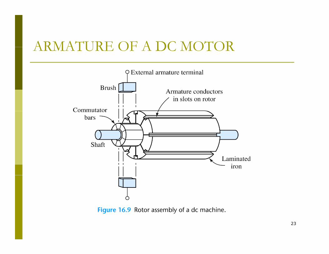
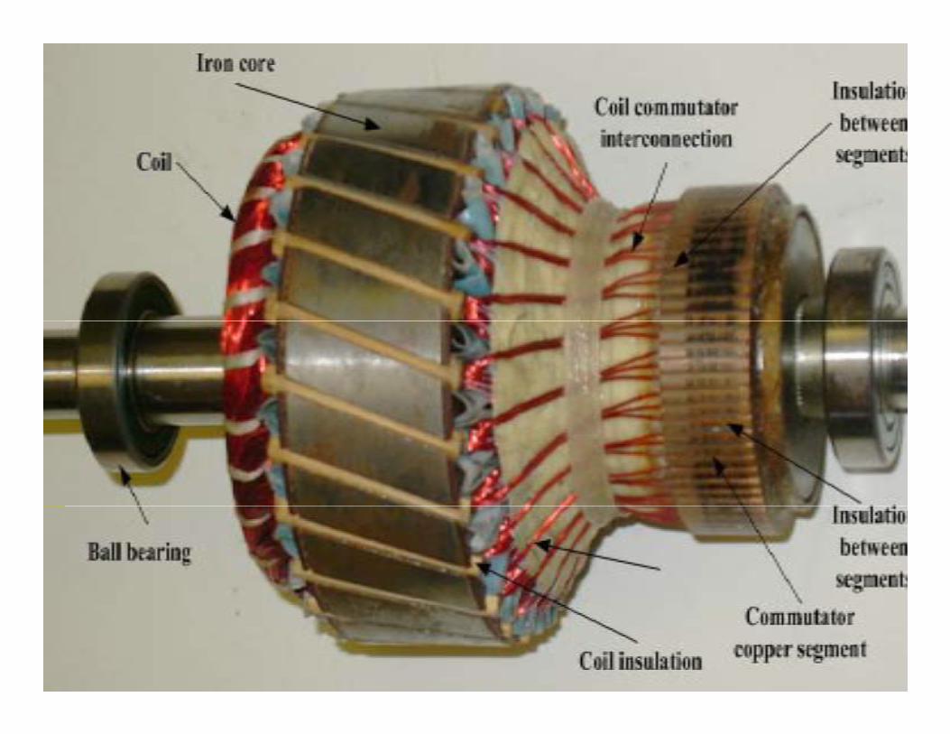
ARMATURE OF A DC MOTORARMATURE OF A DC MOTOR
23
24

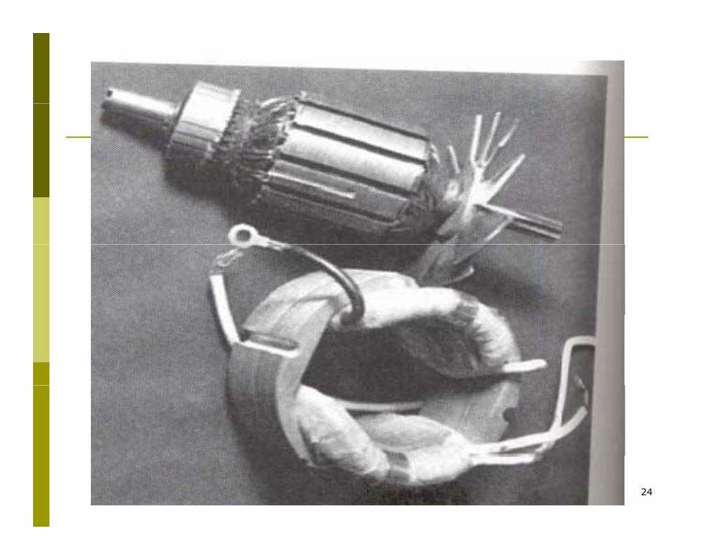
ROTOR CONSTRUCTION:
25

26
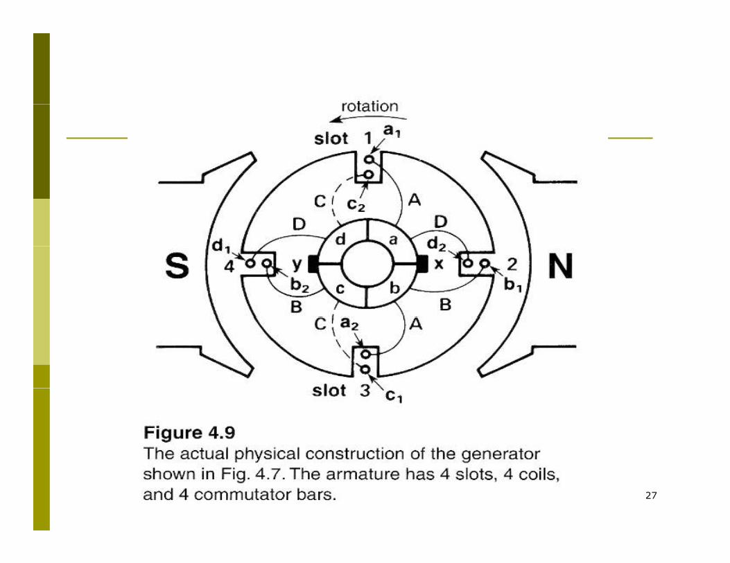
27

Effects of armature reaction and remedy
Armature reaction distorts the flux density distribution,produces demagnetizing effect and shifts the zero fluxp g gdensity region from the q-axis.Poor commutation and sparking.
Rotor mmf neutralized byRotor mmf neutralized by
compensating winding fitted on the main pole faces andconnected in series with armature winding.connected in series with armature winding.Armature current reversal is delayed due to coil inductanceand reactance voltage ie. voltage induced in the moving coilby the quadratic flux.inter pole is needed to compensate armature reactioninter-pole is needed to compensate armature reaction
28

29

30

31

ROTOR WINDING:
- Rotor windings are of two types:- Lap winding- Wave winding
- No. of parallel paths:In lap winding p= no. of polesIn wave winding p= 2
32

Principle of Operation: Armature Voltage
Emfconductor=Flux/rev.= p.ø = p. ø. Nm
Time/rev. 60/Nm 60
Emftotal=Emf conductor X Number of conductor Emftotal Emf conductor X Number of conductor path
Emftotal= p. ø. Nm…(Z/A) = ZNPø ………
60 60 A60 60 A
wherep = number of polesZ = total number of armature conductorsA = number of parallel paths, 2 for wave and p for lap.Φ = flux per pole (Weber)Nm = speed of the armature in the revolutions per minute (rpm)time of 1 revolution = 60/Nm (sec)
33
time of 1 revolution = 60/Nm (sec)

T p f DC r t rTypes of DC generatorsThere are four different methods forThere are four different methods forsupplying the dc current to the motoror generator poles:or generator poles:
– Separate excitationShunt connection– Shunt connection
– Series connectionCompound– Compound
34

Types of DC Machines
Both the armature and field circuits carry direct current in the case of a DC machine.
Types:
S lf it d DC hi h hi li itSelf-excited DC machine: when a machine supplies its own excitation of the field windings. In this machine, residual magnetism must be present in the ferromagnetic circuit of the
hi i d h lf i imachine in order to start the self-excitation process.Separately-excited DC machine: The field windings may be separately excited from an eternal DC source.separately excited from an eternal DC source. Shunt Machine: armature and field circuits are connected in parallel. Shunt generator can be separately-excited or self-excited.
35
Series Machine: armature and field circuits are connected in series.

36

Shunt DC Generator
37

38

Separately-Excited and Self-Excited DC Generators
IfIIL
If+
R
+ IL
Ra
+
DC Supply VtRf
- Ea
+
Ra
Ia
VtRf
Ea
a
- -
Separately-Excited Self-Excitedp y
39

Compound DC GeneratorCompound DC Generator
40
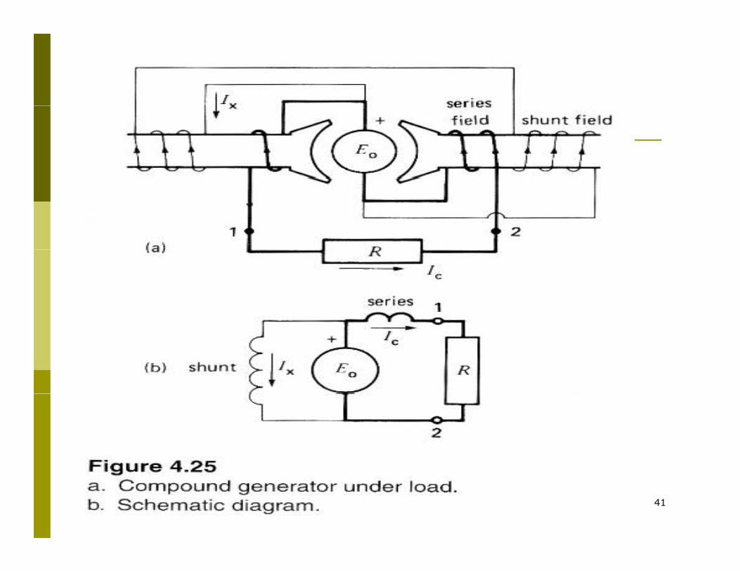
41

Equivalent Circuit of a DC Machine
Ia_gen
I +
If
I+
If
Vf VtRf
+
+
Ia_mot
RaVt
Rf
IL
Ra
- Ea
+
-
IaEa
-+
-
fff RIV =
aaat
fff
RIEV
RIV
±=
42

Generated emf and Electromagnetic Torque
t
fff
RIEV
RIV
±=
= Motor: Vt > EaGenerator: Vt < Ea
aaat RIEV ±=
Voltage generated in the armature circuit due the flux of the stator field current
mdaa KE ωφ=
K : design constant
Electromagnetic torque
Ka: design constant
adae IKT φ=
TIEP ω43
meaaem TIEP ω==

Comparison between the Shunt and Series Connected DC Machines
44

Ar t r R tiArmature Reaction
1. It is the term used to describe the effects of the armature mmf on the operation of a dc machine as a "generator" no matter whether it is a generator or both the flux distribution and the flux magnitude in both the flux distribution and the flux magnitude in motor.
2. It effects the machine.3. The distortion of the flux in a machine is called
iarmature reaction
Two effects of armature reaction:1 Neutral Plane Shift1. Neutral Plane Shift2. Flux Weakening
45
A t R tiArmature Reaction
If a load is connected to the terminals of the dcmachine, a current will flow in its armature windings.machine, a current will flow in its armature windings.This current flow will produce a magnetic field of itsown, which will distort the original magnetic field fromthe machine’s field poles This distortion of the magneticthe machine’s field poles. This distortion of the magneticflux in a machine as the load is increased is called thearmature reaction.
46

ACTION OF A COMMUTATORACTION OF A COMMUTATOR
47

Ar t r R tiArmature Reaction
Effect on flux distribution:Effect on flux distribution:Neutral plane shiftNeutral plane shiftpp
When current is flowing in the field winding, hence a flux is produced across the machine which flows the machine which flows from the North pole to the South pole.
Initially the pole flux is uniformly distributed and the magnetic neutral plane is vertical
48

Ar t r R tiArmature ReactionEffect on flux distribution:Effect on flux distribution:Neutral plane shiftNeutral plane shift
effect by the air gap on the effect by the air gap on the flux field causes the distribution of flux is no longer uniform across the longer uniform across the rotor.There are two points on the periphery of the rotor where periphery of the rotor where B= 0.
49

Armature ReactionEffect on flux distribution:Effect on flux distribution: Neutral Neutral plane shiftplane shiftplane shiftplane shift
The combined flux in the machinehas the effect of strengthening or weakening the flux in the pole.g pNeutral axis is therefore shifted in the direction of motion.The result is current flow circulating between the shorted segments and large sparks at the brushes The large sparks at the brushes. The ending result is arcing and sparking at the brushes.
Solution to this problem:Solution to this problem:Solution to this problem:Solution to this problem:placing an additional poles on the neutral axis or mid-point that will produce flux density component, which counter-acts th t d d b th t
50
that produced by the armature.

51

Schematic Connection Diagram of a DC Machine
52

Short shunt wound compound DC Machine
Series Field Coil
Shunt Field Coil Armature
RA
•If the shunt and series field aid each other it is called a cumulativelyexcited machineexcited machine•If the shunt and series field oppose each other it is called a differentiallyexcited machine
53

Long shunt wound compound machine
Series Field Coil
Shunt Field Coil Armature
RA
•If the shunt and series field aid each other it is called a cumulativelyexcited machineexcited machine•If the shunt and series field oppose each other it is called a differentiallyexcited machine
54

ROTOR WINDING:
- Rotor windings are of two types:- Lap winding- Wave winding
- No. of parallel paths:In lap winding p= no. of polesIn wave winding p= 2
55

DC Generator Characteristics
In general, the following characteristics specify the steady-state performance of a DC generators:
1. Open-circuit characteristics: generated voltage versus field current at constant speed.
2. Load characteristic: terminal voltage versus load current at constant armature current and speed.
56

N L d S t r ti rNo Load Saturation curves
57

Magnetic and Open circuit characteristicsg p
58

Self-Excited DC Shunt GeneratorMaximum permissible value of the field resistance if the terminal voltage has to build up.
59Open-circuit characteristic

DC Generator Characteristics
The terminal voltage of a dcThe terminal voltage of a dc generator is given by
RIEV −=( )[ ]
aa
mf
aaat
RI
dropreactionArmatureIfRIEV
−
−==
ω,
aa
60Open-circuit and load characteristics

L d h r t ri ti f p r t l it d n r t rLoad characteristics of seperately excited generator
61

62

DC Generator Characteristics
It can be seen from the externalIt can be seen from the external characteristics that the terminal voltage falls slightly as the load current increasescurrent increases.
63External characteristics

Electromagnetic Torque
Area per pole A =2πrl/ pFl X densit B/A pø/2 l E IFluX density =B/A=pø/2πrl EaIa
Current / conductor is=Ic= Ia/A
The force on a conductor is F=BlI /AThe force on a conductor is F=BlIa /AThe torque developed by a conductor=F.r
T=rBlIa /A=pøIa/2πaa / p a/The total torque developed is=ZpøIa/2πa=KøIa
=EaIa/wm
64

DC MOTORS
DC motors consist of rotor-mountedDC motors consist of rotor mountedwindings (armature) and stationarywindings (field poles). In all DC motors,except permanent magnet motors, currentmust be conducted to the armature
i di b i t th hwindings by passing current throughcarbon brushes that slide over a set ofcopper surfaces called a commutatorcopper surfaces called a commutator,which is mounted on the rotor.
65

M j r t p f d t rMajor types of dc motors
Self excited dc motorSeries dc motorSh t d tShunt dc motorCompound dc motor
Separately excited dc motorSeparately excited dc motorPermanent magnet dc motor
66
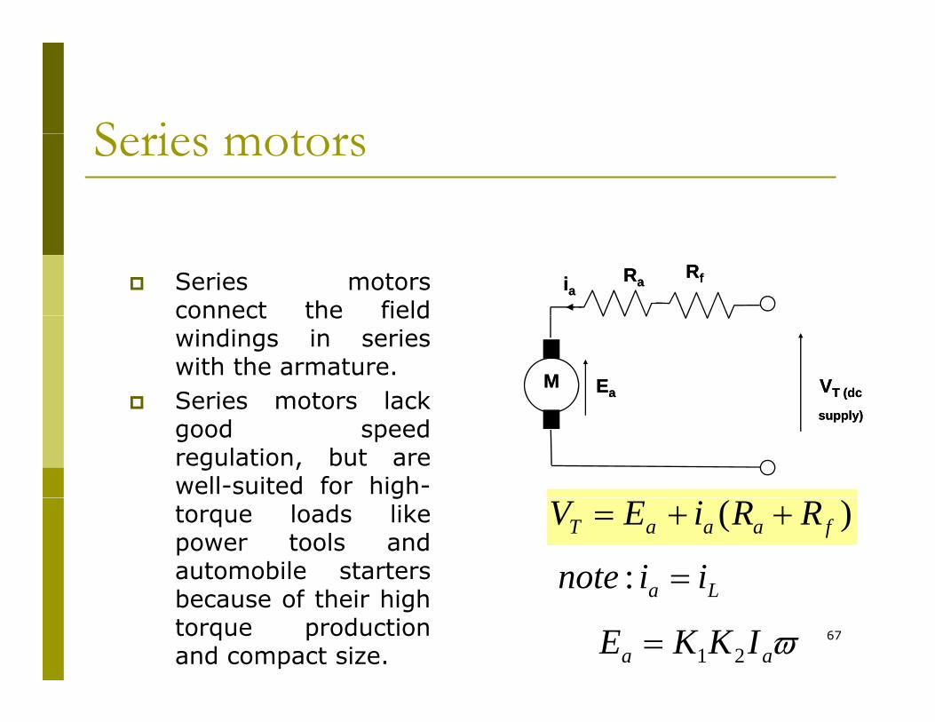
S ri t rSeries motors
Series motorsconnect the field
RRffRRaaiiaaconnect the fieldwindings in serieswith the armature.Series motors lack
EEaaMM VVT (dc T (dc Series motors lack
good speedregulation, but arewell-suited for high-
supply)supply)
gtorque loads likepower tools andautomobile starters
)( faaaT RRiEV ++=
La iinote =:67
because of their hightorque productionand compact size.
La
ϖaa IKKE 21=

Sh t t rShunt motors Shunt motors use highShunt motors use high-resistance field windingsconnected in parallel withthe armature.Varying the field resistance
Raia iL
Varying the field resistancechanges the motor speed.Shunt motors are prone toarmature reaction, adistortion and weakening of Ea VT (dc
if
RfMdistortion and weakening ofthe flux generated by thepoles that results incommutation problemsevidenced by sparking atth b h
Ea VT (dc
supply)
fM
the brushes.Installing additional poles,called interpoles, on thestator between the mainpoles wired in series with
)( aaaT RiEV +=
68
poles wired in series withthe armature reducesarmature reaction.
ffT
faL
RiV
iiinote
=
+=:

C p d t rCompound motors
the concept of the series and the series and shunt designs are combined.
Raia
if
iLRf2
Ea VT (dc
supply)
if
Rf1M)( 2faaaT RRiEV ++=supply)
f
: faL iiinote +=
691ffT RiV =
S p r t l E it d M t rSeparately Excited MotorThere is no direct connection between the There is no direct connection between the armature and field winding resistance
DC field current is supplied by an independent sourcep
(such as battery or another generator or prime mover called an exciter)
70

S p r t l E it d M t r (C t)Separately Excited Motor (Cont)
ΦNZ
Circuit analysis:Ra Laia
RfIfΦ==
Φ= NKNiK
ANZpE fffa 60
Ea
ia
M VTVfLf
If
Where p= no of polesN= speed (rpm)Z=no of conductorΦ=Flux per pole (Wb)
fff RiV =
RiEV +
p p ( )A= no of current/parallel path
=p (lap winding)=2 (wave winding)
KVL:
fff RiV =
RiEV +71
aaaT RiEV +=
La iinote =:aaaT RiEV +=

Sp d tr l f D t rSpeed control of Dc motorsΦNZp
Φ==Φ
= NKNiKA
NZpE fffa 60
aaaT RiEV +=
φKRiV aaTN −=
72
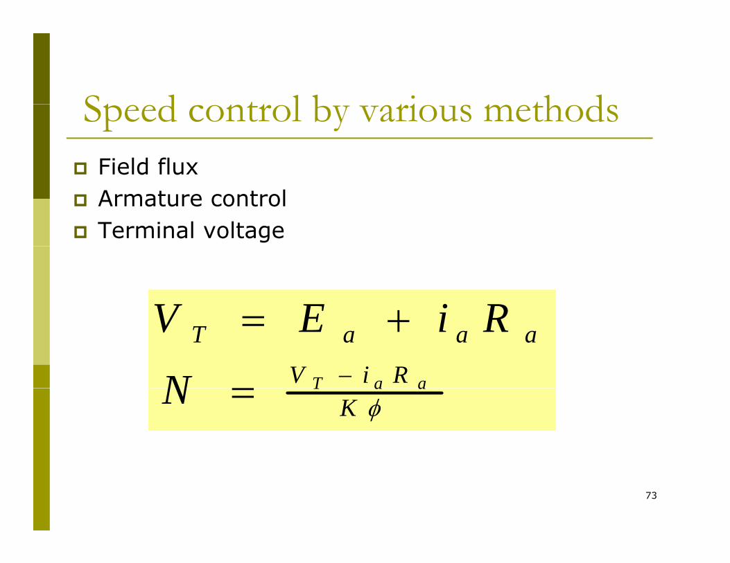
Sp d tr l b ri th dSpeed control by various methodsField flux Armature controlTerminal voltage
RiEV +=RiV
aaaT
aaTN
RiEV−=
+=
φKaaTN =
73

The expressions for motor speed show that the speed of themotor is directly proportional to the armature supply voltage andinversely proportional to the flux per pole. This gives rise to two
74
y p p p p gmethods of controlling the speed of DC motors:

Speed Control for shunt motor and l i d dseparately excited dc motor
i.i. Armature resistance speed controlArmature resistance speed control- Speed may be controlled by changing
Ra
- The total resistance of armature may be varied by means of a rheostat in series with the armatureseries with the armature
- The armature speed control rheostat also serves as a starting resistor
75
also serves as a starting resistor.
Speed Control for shunt motor and l i d dseparately excited dc motor
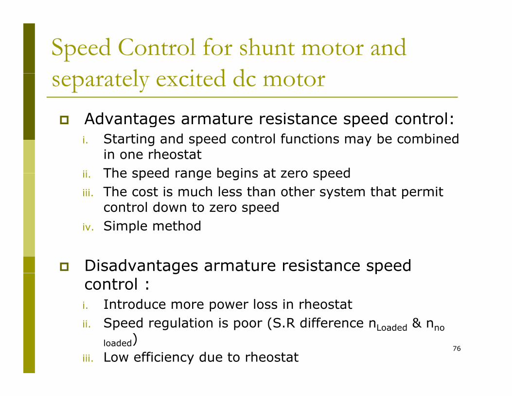
Advantages armature resistance speed control:Advantages armature resistance speed control:i. Starting and speed control functions may be combined
in one rheostatii The speed range begins at zero speedii. The speed range begins at zero speediii. The cost is much less than other system that permit
control down to zero speedSi l th div. Simple method
Disadvantages armature resistance speed g pcontrol :i. Introduce more power loss in rheostatii Speed regulation is poor (S R difference n & n
76
ii. Speed regulation is poor (S.R difference nLoaded & nno
loaded)iii. Low efficiency due to rheostat

Speed Control for shunt motor and l i d dseparately excited dc motor
iiii Field Speed ControlField Speed Controlii.ii. Field Speed ControlField Speed Control- Rheostat in series with field winding
(shunt or separately etc )(shunt or separately etc.)- If field current, If is varied, hence flux
is also variedis also varied- Not suitable for series field
77

Speed Control for shunt motor and l i d dseparately excited dc motor
Advantages field speed control:Advantages field speed control:i. Allows for controlling at or above the base speedii. The cost of the rheostat is cheaper because If is small
value
Disadvantages field speed control :Disadvantages field speed control :i. Speed regulation is poor (S.R difference nLoaded & nno
loaded)ii At high speed flux is small thus causes the speed of ii. At high speed, flux is small, thus causes the speed of
the machines becomes unstableiii. At high speed also, the machines is unstable
mechanically thus there is an upper speed limit
78
mechanically, thus there is an upper speed limit

Speed Control for shunt motor and l i d dseparately excited dc motor
Advantages armature terminal voltage speed control:control:i. Does not change the speed regulationii. Speed is easily controlled from zero to maximum safe
speed
Disadvantages armature terminal voltage speed Disadvantages armature terminal voltage speed control :i. Cost is higher because of using power electronic
controller
79
controller

Field Control:Speed Control in Shunt DC Motors
Field Control:
Ra and Vt are kept constant, field rheostat is varied to change the field current.
I RVtNFor no-load condition, Te=0. So, no-load speed varies i l i h h fi ld
φKIaRaVtN −=
inversely with the field current.
Speed control from zero to base speed is usually obtained by armature voltage control. Speed control y g pbeyond the base speed is obtained by decreasing the field current. If armature current is not to exceed its rated value (heating limit), speed control beyond the base speed is restricted to constant power known as constantspeed is restricted to constant power, known as constant power application.
meaaat TIEconstIVP ω====
80mm
aae
.constIETω
=ω
=

Speed Control in Shunt DC Motorsp
Armature Voltage Control:
Ra and If are kept constant and the armature a f pterminal voltage is varied to change the motor speed.
( ).constis;
KK;
KK
TKVK
ddada
etm
φφ
=φ
=
−=ω
221
21
11
For constant load torque, such as applied by an elevator or hoist crane load, the speed will change linearly with V In an actualchange linearly with Vt. In an actual application, when the speed is changed by varying the terminal voltage, the armature current is kept constant. This method can also
81
be applied to series motor.

Speed Control in Shunt DC Motors
Armature Resistance Control:
Vt and If are kept constant at their rated value, armature resistance is varied.
( ) eeda
adja
da
tm TKKT
K
RRKV
652 −=φ
+−
φ=ω
The value of Radj can be adjusted to obtain various speed such that the armature current Ia(hence torque, Te=KaφdIa) remains constant.
Armature resistance control is simple to implement. However, this method is less efficient because of loss in R d This resistanceefficient because of loss in Radj. This resistance should also been designed to carry armature current. It is therefore more expensive than the rheostat used in the field control method.
82

A t V lt C t l
Speed Control in Series DC Motors
Armature Voltage Control:
A variable dc voltage can be applied to a series motor to control its speed. A variable dc voltage can be obtained from a power electronic converterfrom a power electronic converter.
( )( )d
saaat
asd
RRIKRRIEV
IK
++ωφ=
++=
=φ
( )( ) ( )
samsa
ta
saamasa
saamda
RRKKVI
RRIIKKRRIK
++ω=
++ω=
++ωφ=
Torque in a series motor can be expressed as
asaadae
VKK
IKKIKT =φ=2
2
( )[ ]
sae
t
sa
sa
sae
tm
samsa
tsa
KKTV
KKRR
KKTV,or
RRKKVKK
≈+
−=ω
++ω= 2
2
83
saesasae

Speed Control in Series DC Motors
Field Control:
Control of field flux in a sries motor is achieved by using a diverter resistanceusing a diverter resistance.The developed torque can be expressed as.
aad
saadae IKIRR
RKKIKT ρ=⎟⎟⎠
⎞⎜⎜⎝
⎛+
=φ= 22
ds
dsa
ds
RRRandKKK,where
RR
+=ρ=
⎟⎠
⎜⎝ +
aasamda
aaads
dsat
RIRIK
RIIRR
RREV
+ρ+ωφ=
+⎟⎟⎠
⎞⎜⎜⎝
⎛+
+=
( ) ( )( ) aasm
aasmasa
aasamda
VIRRK
IRRIKK+ρ+ρω=
+ρ+ωρ=
ρφ
84asm
ta RRK
VI,or+ρ+ρω
=

Speed Control in Series DC Motors
2⎟⎞
⎜⎛ tVKT ⎟⎟
⎠
⎞⎜⎜⎝
⎛+ρ+ρω
ρ=asm
te RRK
KT
85

Armature Resistance Control:
Speed Control in Series DC MotorsArmature Resistance Control:
Torque in this case can be expressed as
( )2tKVT =
Rae is an external resistance connected in series with the armature.
( )2msadjae
KRRRT
ω+++
For a given supply voltage and a constant developed torque, the term (Ra+Rae+Rs+Kωm) should remain constant. Therefore, an increase in Rae must be accompanied by a corresponding decrease in ω .accompanied by a corresponding decrease in ωm.
( )T
KVKRRRe
tmsadja =ω+++
22
RRRVor
VTKKRRR,or
sadjat
te
msadja
++=ω
=ω+++
86
KKT,or
em −=ω
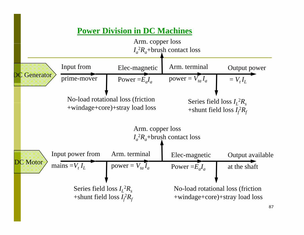
Power Division in DC MachinesArm. copper loss
Input from Elec-magnetic Arm. terminal Output power
Arm. copper loss Ia
2Ra+brush contact loss
DC G t prime-mover Power =EaIa power = Vta Ia = Vt IL
No-load rotational loss (friction Series field loss IL2R
DC Generator
(+windage+core)+stray load loss
Series field loss IL Rs +shunt field loss If
2Rf
Arm. copper loss
Input power from Elec-magneticArm. terminal Output available
Ia2Ra+brush contact loss
DC Motor mains =Vt IL Power =EaIapower = Vta Ia at the shaft
No-load rotational loss (frictionSeries field loss IL2Rs
DC Motor
87
(+windage+core)+stray load loss
L s +shunt field loss If
2Rf

EfficiencyEfficiency
InputPowerOutputPower
=η
InputPowerLossesInputPower
InputPower−
=
InputPowerLosses
−= 1
The losses are made up of rotational losses (3-15%), armature circuit copper losses (3-6%) and shunt field copper loss (1-5%)circuit copper losses (3 6%), and shunt field copper loss (1 5%). The voltage drop between the brush and commutator is 2V and the brush contact loss is therefore calculated as 2Ia.
88

DC Machines Formulas
89