Embed Size (px)
Citation preview

DATA SHEET: TDS102.B100
RANGE10kW to 625kW
We are consuming and exhausting energy feedstocks (coal, gasand peat) that took Nature millions of years to develop. Weextract these resources from deep layers in our Earth and thenburn them, causing pollution of the environment and theatmosphere, with partly irreversible adverse effects. In the future,energy resources will be obtained from the surface and not frominside the Earth. The R Series boiler bridges the gap between gascondensing boilers and bio-liquid boilers by providing combustionwhich burns traditional fuels and also ‘green fuels’ in a year-roundhigh efficiency condensing manner.
R SERIES CONDENSINGB100 BIO-FUEL BOILERburning B100 bio-fuel oil transformedfrom waste oil and rape seed oil
ATLANTICBOILERS
HIGH EFFICIENCY CONDENSING BOILER-PLANT
90% and above A A
86% - 90% B
82% - 86% C
78% - 82% D
74% - 78% E
70% - 74% F
Below 70% G
SEDBUK EFFICIENCY RATING 2005
ENERGY RATING “A”
CE-0645 BL105tested
Efficiency between 92% and 99% GCV
Higher efficiency at maximum mid-winter load
Environmentally friendly
Year round condensing boiler even with constant temperature82ºC-71ºC
On/off, high/low/off and modulating burners available depending on output

The R Series year-round maximum condensing boiler has two distinct heat exchangers, the first of quality steeldesign and the second of high-grade plastic design. The flue gases leave the first heat exchanger at temperaturesbelow 90°C, and are then extracted from the second condensing heat exchanger at temperatures below 50°C. Forcombustion air entry temperatures below 30°C, efficiencies are obtained which are in excess of 92% GCV throughoutthe heating season. These conditions apply throughout the year in the UK.
ABOUT THE B100 BIO-FUEL R-SERIES CONDENSING BOILERThe bio-fuel is kept at temperatures just above freezing in anexternal or bunded vessel, then piped to a pre-heat tank withinthe R Series boiler, from which it passes to the burner. B100 isdeveloped from organic material and burns with the samemaximum condensing efficiency as fuel oil and natural gas.
Approximately 12 litres of air is needed for each 1 litre of B100bio-diesel so that the volume of hot flue gases is considerableand represents a substantial waste of energy. This energy ispartly in the form of sensible heat due to the elevatedtemperature of the gases, and partly as latent heat in the watervapour. The latent heat amounts to around 7% of the grosscalorific value of the fuel.
R Series condensing boilers are designed to recover much ofthe heat in the flue gases and consequently operate at muchhigher efficiencies. If the flue gases are cooled down to theirdew point - (50˚C for B100) - much of the latent heat, as wellas the sensible heat, can be recovered. The R Series boiler,designed to always operate in the condensing mode, usescorrosion resistant plastic materials for all of the condensingheat exchanger and contains limestone granules to treat theacidic condensate before safe disposal to a drain.
BIO-LIQUIDS Since 2006 we have discovered that using oil,obtained directly from organic material as afuel, does not always burn reliably. We havenow turned to using waste oil, animal fatsand vegetable oil which have been modified.
The modification to these oils (or the oiltransformation process) is thetransesterification of one form of ester toanother. Although the exact percentagevaries somewhat depending on what kindof plant the oil comes from, approximately20% of a vegetable oil molecule iscomposed of glycerine. During thetransesterification process, alcohol is
added, and each of the fatty acid chainsattaches to one of the new alcoholmodules, creating three monolynealkyl-esters. This process makes the esters thinnerand more suitable for use on burners. Onceseparated from the glycerine, the alkyl esterchains are called bio-diesel.
The remarkable feature of thetransesterification process is that it canuse a wide range of feed stocks, virginvegetable oils, used fryer oil, animal fats,even pond algae – to produce the samebasic bio-diesel end product (with minordifferences in fuel characteristics). Thisability to adapt the production process tolocally available feed stocks is an important
advantage. It allows the customer toconsider various sources of bio-diesel. Areliable 'green' modified oil is B100 madeand tested to EN 14214 standards.
B100 makes certain demands on its storageand feed to the burner. Acceptablematerials are carbon steel and 316Lstainless steel’, copper, brass and bronzemust not be used. There must be a carefulselection and use of jointing materials. Allrubber based material cannot be used.
B100 must be kept up to the minimumtemperature of 5°C and in the range 5°C to15°C. There must be good pressure controlof B100 at the storage tank and in thepumped feed distribution.
MAIN HEATEXCHANGER
CONDENSINGEXCHANGER
HEATING FLOW& RETURN
FRESH AIR
FLUE GASES
TREATEDCONDENSATE
BIO-FUEL PRE-HEATING TANK
FROM BIO-FUELSTORAGE TANK
BURNER
ABOUT THE ATLANTIC R-SERIES BOILER

Model 17 22 40 60 90 150 200 300 400 500 600Maximum Output kW 17 22 40 60 90 150 210 315 370 485 625
Minimum Output kW 10 15 12 20 33 40 42 80 80 80 150
Full load efficiencyAmbient air 22ºC B100 % gcv 93.5 95.0 95.3 94.7 93.2 96.6 94.0 95.3 92.5 94.5 94.4
Gas % gcv 90.6 92.2 92.9 91.9 90.4 93.7 91.2 92.4 89.7 91.7 91.6Fuel used B100 Litres/hr 2.2 2.8 5.1 7.7 11.6 19.2 26.9 40.4 47.4 62.2 77.6
Gas m³/hr 1.7 2.0 4.0 6.0 9.6 15.0 19.8 30.0 46.3 53.1 63.5
Exit Flue gases @ 30ºC B100 m³/hr 23 30 55 82 124 206 274 411 547 684 893
Gas m³/hr 25 34 61 92 138 230 306 460 613 767 920
Dry weight kg 125 200 300 438 794 996 1014 1790 1975 2100 2225
Water contents ltrs 36 36 75 80 197 330 500 910 1010 1110 1475
Min water pressure BARS 0.5 0.5 0.5 0.5 0.5 0.5 0.5 0.5 0.5 0.5 0.5
Water pressure BARS 3.0 3.0 3.0 3.0 3.0 3.0 3.0 3.0 3.0 3.0 3.0
Max (on order) BARS 7.0 7.0 7.0 7.0 7.0 7.0 7.0 7.0 7.0 7.0 7.0
Model 17 22 40 60 90 150 200 300 400 500 600Height mm 1165 1365 1510 1645 1740 1945 1985 2070 2220 2220 2550
Width mm 350 445 545 550 740 885 1225 1225 1425 1425 1425
Depth mm 940 1000 1220 1330 1750 2030 3140 3770 3770 3770 3770
Height-demountable mm 600 750 895 985 965 1070 1281 1370 1400 1400 1510
Width-demountable mm 410 445 545 550 740 885 1225 1225 1225 1225 1225
Depth-demountable mm 645 680 760 784 1130 1255 1340 1970 1970 1970 1970
Access front mm 500 500 500 700 1000 1000 1000 1000 1000 1000 1000
Access one side mm 100 100 100 100 100 100 100 100 100 100 100
Access other side mm 500 500 500 500 500 500 500 500 500 500 500
Access rear mm 300 300 300 300 300 300 300 300 300 300 300
Access top mm 300 300 300 300 300 300 500 500 500 500 500
Model 17 22 40 60 90 150 200 300 400 500 600Fresh air inlet mm 75 75 75 75 110 110 125 125 150 150 200
Warm air burner inlet mm 50 50 50 70 100 100 125 125 150 150 200
Fresh gas outlet mm 75 75 75 75 110 125 200 200 200 200 200
Heating flow mm 25 25 25 25 40 50 65 65 80 80 100
Heating return mm 25 25 25 25 40 50 65 65 80 80 100
Hot water primaries mm 25 25 25 25 32 40 50 50 50 50 50
Condensate mm 50 50 50 50 50 50 50 50 50 50 50
The boiler body is made of 3mm thickquality steel with a water-cooled combustionchamber. The burner fires horizontally throughthe combustion chamber and makes a seriesof passes through a horizontal heatexchanger. The steel boiler is externallycovered with an 80mm layer of rock woolthermal insulation. Access to the heatexchanger is through a panel at the front ofthe boiler secured by four bolts.
The condensing exchanger is made ofpolypropylene and contains a series ofsmooth polypropylene heat exchanger tubes.The bottom of the condensing exchanger hasa section containing limestone granules toneutralise the condensate.
The boiler has a pre-wired control panelincorporating an isolator switch with indicatorlamps, modulating, high/low or on/off burnercontrol, water flow sensor with indicatorlamps, a safety limit thermostat, hours runindicator, flue gas thermometer and aweather-controlled programme.
The boiler assembly includes a 4 way valve,a shunt pump, both pre-wired and operatedby the control panel, and a shunt pipearrangement with connections for a restrictedconstant temperature circuit.
The pressurised B100 or gas burner has;aluminium body, motorised fan air supply, oilor gas valve with controlled rate of opening,ignition transformer, air/B100 or air/gasmixing, combustion head, differential pressure
switch, control box with ionisation flameprotection, balanced flue pressure switchcontrols. Burners are available with pre-mix,modulating, high/low and on/off operationdepending on fuel type and model size.
The flue gas fan(s) in each boiler assemblycontain - aerodynamic polypropylenehousing, vibration free mountings, minimumpressure loss inlet & outlet, totally enclosedsynchronous motor, maintenance free, dust &water proof bearings, infinitely adjustable fanmotor speed regulator. The number of fansdepends on the boiler model. From themodel R22-15 to the model R22-90 the fan ismounted within the boiler casing. Frommodel R22-150 upwards, the multi-fanassembly is mounted to the rear of the boiler.
SPEC
IFICA
TION
PERFORMANCE, DIMENSIONS & CONNECTIONS
PER
FOR
MA
NC
ED
IMEN
SION
SC
ON
NEC
TION
S

Provision must be provided on site for B100 storage.General guidance is provided by OFTEC OFST200 oil firingequipment standard and OFTEC SP697.432 oil fired heatingsystem design.
It is usual to provide storage in sufficient quantity to enablethe boiler plant to run at full load for either a period ofthree weeks plus 10% sump content or for a period of fourweeks. This should allow for severe winter weather causingdisruption of supplies. Also, seasonal price variations orother price considerations may make it attractive to store fora longer period.
Typical calculation: School 315kW boiler heating running 60 hrs per weekFull load consumption: 4 weeks x 60hrs x 40.4ltrs = 9696 ltrsTherefore, select 10,000 litres capacity tank
Capacity Single skin Double skin bundedLitres length diameter length diameter
2000 1860 1250 2050 12653000 2710 1250 3000 12654000 3540 1250 3900 12655000 3130 1500 3450 15158000 3305 1900 3650 191510000 4025 1900 4450 191515000 5810 1900 6400 191520000 4690 2500 5200 252030000 6700 2500 7400 2520
TYPICAL HORIZONTAL STEELOIL STORAGE TANKS
MS
S - SludgeFr - Feed returnM - Manhole plate with 5 connectionsF - Fill
Fr F H1 H2T V Ff
H1/H2 - HeatersT - ThermostatsV - VentFf - Feed flow
Welded Cradles
SIDE ELEVATION
TOP VIEW
B100 BIO-FUEL PIPE SIZINGThe piping system used to conveyB100 oil to oil-fired burners requirescareful design considerations. Pipesizing must be large enough tomaintain low pump suction head and,as B100 fuel requires a circulatingloop system, must prevent over-pressure at the burner oil pump inlet.B100 has a kinematic viscosity of 4.5centi-Stokes at 40˚C as comparedwith diesel oil kinematic viscosity of3.0 centi-Stokes.
Pipe materials must be compatiblewith the B100 fuel and must becarefully assembled to eliminate allleaks. Leaks in suction lines causepumping problems that result inunreliable burner operation. Leaks inpressurised lines create fire hazards.Only carbon steel and, preferably,austenitic stainless steel materials aresuitable. Pipe jointings and
compounds must be chosen carefully.Where valves are fitted, they shouldbe carefully selected of the ball-type.
B100 pump suction lines should besized so that at maximum suction lineflow conditions, the maximum vacuumwill not exceed 3kPA. B100 supplylines to burner oil pumps should notbe pressurised by circulating loopsystems to more than one third of abar or seals may fail. Care should beexercised in assembling long B100fuel pipe lines to avoid air pockets.On overhead circulating loops. Theline should vent air at all high points.
On overhead circulating loops, theline should have provision for airventing at all high points, oil supplyloops for one or more burners shouldbe of continuous circulation, withexcess fuel returned to the storage
tank. With any dead-end pressurisedloops, air or B100 vapour venting maybe a problem. With any single feedlines to burners, vents are likely to berequired in order to vent air or B100vapour formed under vacuum.
A study at BSRIA indicates that B100must be maintained in storage and incirculating pipework at a minimumtemperature of 5˚C and generally inthe range 5˚C to 15˚C. Typical B100circulating loops between storagetank and boilers are shown on thenext page.
Oil lines should be tested afterinstallation, particularly if buried,enclosed or inaccessible. Pressurisedlines should be tested at 1.5 xmaximum working pressure; Suctionlines should be tested at minus 3kPA;tests should last 60 mins.
B100 BIO-FUEL STORAGE

STEEL CYLINDRICAL TANK
R-SERIES B100BIOFUEL BOILER
OVER-FLOW VALVE
DUPLEX PUMPS
BIO-FUEL PRE-HEATING TANK
BIO-FUEL PRE-HEATING TANK
BIO-FUEL PRE-HEATING TANK
FILL
PUMP
R-SERIES B100BIOFUEL BOILER
PRESSUREBALANCINGREGULATOR
HIGH GRADE PLASTIC TANK
1 BOILER, 1 TANKFor smaller installations, 150kWand below, an economicsubmersible pump will lift theB100 from the tank into thevicinity of the boiler and apressure balancing regulator.From the regulator, the B100 isfed at reduced pressure into theintegral boiler hot tank fromwhich a 2-pipe system serves theB100 to the burner. The storagetank may be of plastic or steelconstruction, having integralbackground electrical heatingand possibly some degree ofthermal insulation.
2 BOILERS, ONE TANKFor larger installations of twoboilers or more, a duplex in-line pumping system transfersthe B100 to each boiler,through the integral boiler hottank. Pressure in the feed circuitis regulated at the in-linepumps and in an overflowvalve placed in the return
PLEASE CALL ATLANTIC FOR THE
FULL DESIGN SERVICE
B100 BIO-DIESEL STORAGE AND FEED CIRCUITS

Duplex Domestic Hot Water Priority
BALA
NCIN
G V
ESSEL
Weather Compensated Space Heating
ACFE Auto top up unit and fast fill bypass kit
Constant Temperature
Variable Temperature
DHWPHE PHE
Domestic Hot Water Priority
Balancing Vessel
Weather compensatedspace heating
ACFE Auto top up unit and fast fill bypass kit
DHW
Each boiler has its own header with in-built 4-port valve and shunt pump. This guaranteesminimum water flow and temperature control. Single and group boilers can use a balancing &sedimentation vessel or a low velocity header as a neutral heat outlet. Any number of circuits,in order of priority, can then be served adequately from the boiler(s).
PIPEWORK ARRANGEMENTS
TYPICAL ONE BOILERARRANGEMENT One R22 boiler servesdomestic hot water (priority)and weather compensatedradiators The fast-responseindirect cylinder always needsto receive primary hot waterwithin 1 or 2 minutes ofdemand so it receives priorityfrom the balancing vessel orheader. The radiators have aresponse time of about 20minutes so they take primaryheat as a second function.Consequently the indirectcylinder is served first from thebalancing vessel.
MULTIPLE BOILER ARRANGEMENT This might be a typical medical centre situation where duty & standby boilerplant serves sanitary hot water, air conditioning and underfloor space heating.The ultra-fast response plate heat exchangers need primary heating within afew seconds, the air conditioning (in mid-winter) needs primary heating withina few minutes, whereas the underfloor space heating has a much longerresponse time. The plate heat exchangers are served first from the balancingvessel, the air conditioning second and the under-floor heating last.

The balancing vessel is located close to the boilers, with its feet placed on abase to allow the boiler flows and returns to normally vent to the vessel. Onefull size cold feed pipe should be taken to the connection ’P’ on the vesseland fitted with a ‘normally open’ ball valve, allowing unrestricted heatingsystem expansion and contraction to take place along the pipe.
The different flow pipes of separate heating circuits should be connectedprogressively down the header from the top flow 'A'. The returns should beconnected similarly upwards from the bottom return 'I'. DHW priority flow andreturn circuits should be taken from and to the high level ‘W’ tappings.
When connections are complete and the system is ready for filling. Firstlyeverything should be isolated from the vessel. This includes the boilers (withtheir shunt pumps) connected to ‘L’ (flow) and ‘M’(return) and the heatingcircuits - 'A' and 'I'. - which should be isolated from the vessel. The vessel airvent ‘V’ and drain/sludge valve ‘D’ should be closed.
The different heating circuits should then be filled separately. As the circuitsare progressively filled, they should beregularly sludged through the bottom of thevessel by opening the circuit valves and thedrain and sludge valve until the water clears.This should be repeated for all the circuits.After filling all the circuits, the circuit pumpsshould be set running to check for furthersedimentation arriving in the vessel. Whenthis is clear, the boiler valves may be slowlyopened and then the shunt pumps setrunning.
A
I
W
W
P
M
L
V
D
BALANCING AND SEDIMENTATION
VESSEL
BSV AND SVSTANDARD DIMENSIONS
Capacity Diameter116kW 100mm348 kW 150mm696 kW 200mm1740 kW 300mm2900 kW 500mm
The Dunphy 'T' series burner allowsmanual or automatic changeoverbetween different fuels - B100 bio-diesel, natural gas, LPG, light oiland kerosene. A controlled anduniform pattern of air distributionenhances the high efficiency of theequipment and facilitates theutilisation of pollution reduction
techniques. In addition, the co-axialdesign has the added advantage ofbeing extremely quiet in operation.
Within buildings used for essentialpurposes, there is a concern thatsources of new fuels may dry-upand be scarce. In this situation,green boilers may require 100%
standby boilerplant of analternative fuel. The R Series boiler,with its multi-fuel selection, does notrequire the additional boiler facilityand its cost. Also the dual-fuelarrangement enables the Client tocounter-balance fuel cost with theability to burn green fuel.
BSV116
BALANCING AND SEDIMENTATION VESSEL
THE ADVANTAGES OF DUAL BIO-FUEL/GAS BURNERS
B100 PUMP& MOTOR
GAS INLET
GAS TRAIN
B100 INLET
FLAMEFUEL
WARMED INLET AIR
Dunphy Burner Illustrationshowing gas and
B100 bio-fuel suppliers
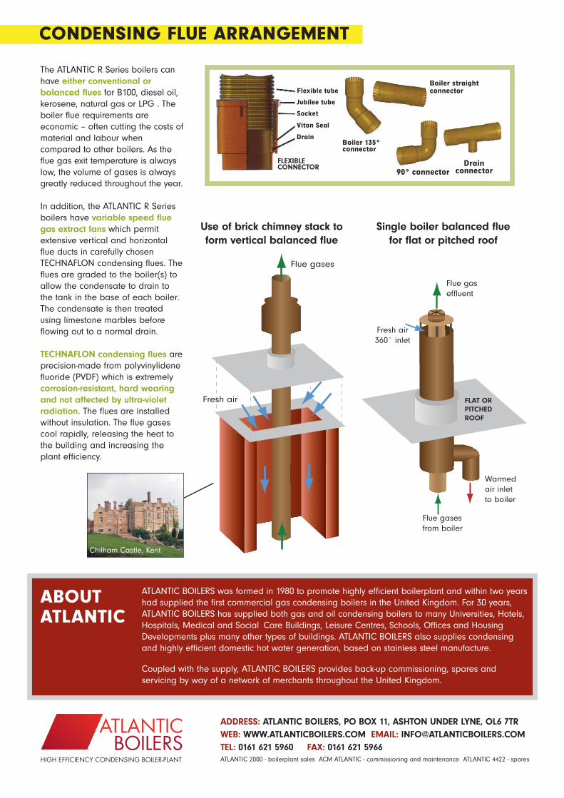
The ATLANTIC R Series boilers canhave either conventional orbalanced flues for B100, diesel oil,kerosene, natural gas or LPG . Theboiler flue requirements areeconomic – often cutting the costs ofmaterial and labour whencompared to other boilers. As theflue gas exit temperature is alwayslow, the volume of gases is alwaysgreatly reduced throughout the year.
In addition, the ATLANTIC R Seriesboilers have variable speed fluegas extract fans which permitextensive vertical and horizontalflue ducts in carefully chosenTECHNAFLON condensing flues. Theflues are graded to the boiler(s) toallow the condensate to drain tothe tank in the base of each boiler.The condensate is then treatedusing limestone marbles beforeflowing out to a normal drain.
TECHNAFLON condensing flues areprecision-made from polyvinylidenefluoride (PVDF) which is extremelycorrosion-resistant, hard wearingand not affected by ultra-violetradiation. The flues are installedwithout insulation. The flue gasescool rapidly, releasing the heat tothe building and increasing theplant efficiency.
Flue gaseffluent
Fresh air360˚ inlet
Warmedair inletto boiler
Flue gases from boiler
FLAT OR PITCHEDROOF
ATLANTICBOILERS
HIGH EFFICIENCY CONDENSING BOILER-PLANT ATLANTIC 2000 - boilerplant sales ACM ATLANTIC - commissioning and maintenance ATLANTIC 4422 - spares
Flue gases
Fresh air
Use of brick chimney stack toform vertical balanced flue
Chilham Castle, Kent
Single boiler balanced flue for flat or pitched roof
Boiler straightconnector
90° connectorDrain
connector
CONDENSING FLUE ARRANGEMENT
ATLANTIC BOILERS was formed in 1980 to promote highly efficient boilerplant and within two yearshad supplied the first commercial gas condensing boilers in the United Kingdom. For 30 years,ATLANTIC BOILERS has supplied both gas and oil condensing boilers to many Universities, Hotels,Hospitals, Medical and Social Care Buildings, Leisure Centres, Schools, Offices and HousingDevelopments plus many other types of buildings. ATLANTIC BOILERS also supplies condensingand highly efficient domestic hot water generation, based on stainless steel manufacture.
Coupled with the supply, ATLANTIC BOILERS provides back-up commissioning, spares andservicing by way of a network of merchants throughout the United Kingdom.
ABOUTATLANTIC
Boiler 135°connector
Flexible tube
Jubilee tube
Socket
Viton Seal
Drain
FLEXIBLE CONNECTOR
ADDRESS: ATLANTIC BOILERS, PO BOX 11, ASHTON UNDER LYNE, OL6 7TR WEB: WWW.ATLANTICBOILERS.COM EMAIL: [email protected] TEL: 0161 621 5960 FAX: 0161 621 5966