Embed Size (px)
Citation preview
B100i Engine
Operation & Service Manual
B100i Operation & Service Manual Page 1 of 20 15 June 2018
B100i Engine Operation and Service Manual
Rev 1.0
Power 4 Flight Inc 202 Wasco Loop, Suite 104
Hood River OR 97031 USA
Email: [email protected] Tel: +1 541 308 0650
B100i Engine
Operation & Service Manual
B100i Operation & Service Manual Page 2 of 20 15 June 2018
Contents
1. Engine Details .............................................................................................................................. 5
2. Safety Precautions ........................................................................................................................ 5
2.1 Standard safety instructions ................................................................................................... 5
2.2 Engine starting safety ............................................................................................................. 6
2.3 Fuel system pressure ............................................................................................................. 6
3. Installation Guidelines ................................................................................................................... 6
3.1 Engine mount ....................................................................................................................... 6
3.2 ECU mount ........................................................................................................................... 7
3.3 ECU harness .......................................................................................................................... 7
3.4 Induction assembly ................................................................................................................ 8
3.5 Exhaust ................................................................................................................................ 8
3.6 Fuel system ........................................................................................................................... 8
3.7 Cooling ............................................................................................................................... 10
4. Pre-Flight Checklist ..................................................................................................................... 10
4.1 Exhaust mounts secure ........................................................................................................ 10
4.2 Air filter secure and in good condition ................................................................................... 11
4.3 Fuel filter secure and in good condition ................................................................................. 11
4.4 Fuel tank vent clear of obstruction ........................................................................................ 11
4.5 Engine free from fuel and oil leaks ......................................................................................... 12
4.6 Engine rotates freely ............................................................................................................ 12
4.7 Spark plug and cap .............................................................................................................. 12
4.8 High tension lead cover not damaged .................................................................................... 13
4.9 Electrical wires not rubbing or damaged ................................................................................ 13
4.10 Throttle servo linkage does not contact any surrounding parts ................................................. 13
4.11 Throttle linkage secure ......................................................................................................... 13
4.12 Check propeller and spinner general condition ....................................................................... 14
4.13 Fuel lines free of kinks .......................................................................................................... 14
4.14 Expected RPM and CHT at wide open throttle ......................................................................... 14
5. Engine Operation ........................................................................................................................ 14
5.1 Recommended fuel and oil ................................................................................................... 14
5.2 Starting the engine .............................................................................................................. 15
5.3 Engine warm-up .................................................................................................................. 15
5.4 Cylinder head temperature (CHT) .......................................................................................... 15
5.5 Aircraft crash or severe propeller strike ................................................................................. 16

B100i Engine
Operation & Service Manual
B100i Operation & Service Manual Page 3 of 20 15 June 2018
6. Service items .............................................................................................................................. 16
7. Major maintenance items ............................................................................................................ 16
8. Supplemental instructions ........................................................................................................... 18
8.1 100-hour PRX muffler rotation (if equipped) ........................................................................... 18
8.1.1 Procedure .................................................................................................................... 19
9. Document History....................................................................................................................... 20
B100i Engine
Operation & Service Manual
B100i Operation & Service Manual Page 4 of 20 15 June 2018
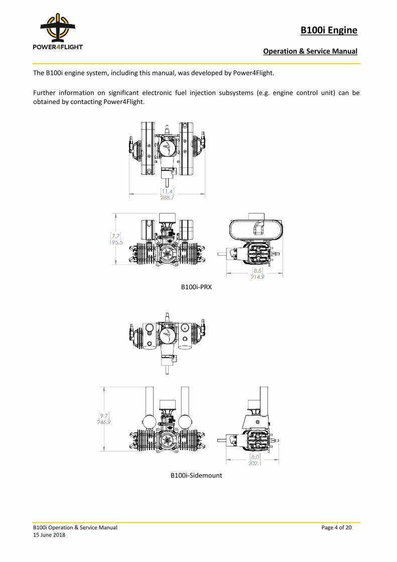
The B100i engine system, including this manual, was developed by Power4Flight.
Further information on significant electronic fuel injection subsystems (e.g. engine control unit) can be obtained by contacting Power4Flight.
B100i-PRX
B100i-Sidemount
B100i Engine
Operation & Service Manual
B100i Operation & Service Manual Page 5 of 20 15 June 2018
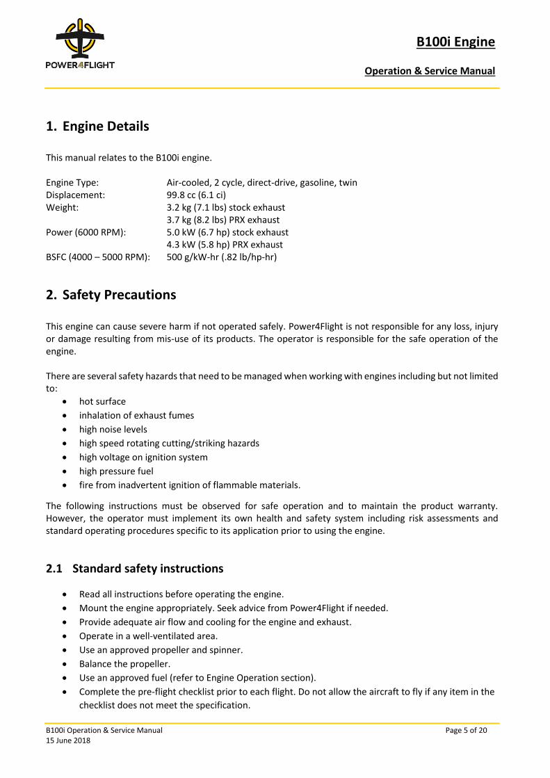
1. Engine Details
This manual relates to the B100i engine. Engine Type: Air-cooled, 2 cycle, direct-drive, gasoline, twin Displacement: 99.8 cc (6.1 ci) Weight: 3.2 kg (7.1 lbs) stock exhaust 3.7 kg (8.2 lbs) PRX exhaust Power (6000 RPM): 5.0 kW (6.7 hp) stock exhaust 4.3 kW (5.8 hp) PRX exhaust BSFC (4000 – 5000 RPM): 500 g/kW-hr (.82 lb/hp-hr)
2. Safety Precautions
This engine can cause severe harm if not operated safely. Power4Flight is not responsible for any loss, injury or damage resulting from mis-use of its products. The operator is responsible for the safe operation of the engine. There are several safety hazards that need to be managed when working with engines including but not limited to:
• hot surface
• inhalation of exhaust fumes
• high noise levels
• high speed rotating cutting/striking hazards
• high voltage on ignition system
• high pressure fuel
• fire from inadvertent ignition of flammable materials.
The following instructions must be observed for safe operation and to maintain the product warranty. However, the operator must implement its own health and safety system including risk assessments and standard operating procedures specific to its application prior to using the engine.
2.1 Standard safety instructions
• Read all instructions before operating the engine.
• Mount the engine appropriately. Seek advice from Power4Flight if needed.
• Provide adequate air flow and cooling for the engine and exhaust.
• Operate in a well-ventilated area.
• Use an approved propeller and spinner.
• Balance the propeller.
• Use an approved fuel (refer to Engine Operation section).
• Complete the pre-flight checklist prior to each flight. Do not allow the aircraft to fly if any item in the
checklist does not meet the specification.
B100i Engine
Operation & Service Manual
B100i Operation & Service Manual Page 6 of 20 15 June 2018
• Ensure that the service items and major maintenance items are up-to-date.
• Ensure that the aircraft is properly secured when starting or operating the engine.
• Do not operate the engine and propeller near loose material that could be drawn into the propeller.
• When the propeller is spinning, ensure that all people remain clear of the plane of the propeller.
• Do not try to start the engine by hand.
• Do not touch the ignition system during operation.
• Wear appropriate personal protective equipment when operating the engine.
• Store flammable liquids in approved containers and in well ventilated areas.
• Allow the engine to cool before touching, especially parts that are near the exhausts. Do not reach
around a hot engine.
2.2 Engine starting safety
The engine is usually started using an external electric engine starter to spin the propeller. Although it is unlikely the engine will start by hand-turning the prop, always treat a “live” engine as though it may start at any moment and take adequate safety precautions. If the engine is inadvertently started during hand cranking, it could pose a risk to people working on or near the engine. It is important that the operator implements a system to prevent inadvertent starting of the engine. The engine control unit (ECU) has a safety feature where the engine can be enabled or disabled. Refer to the ECU Manual for more details.
2.3 Fuel system pressure
The B100i system uses a fuel pressure of 3 bar (44 psi) for petrol/gasoline engines. On typical installations, the fuel lines that are on the downstream side of the pump (i.e. high-pressure lines) are recognizable by the red Festo tubing. The fuel system is a returnless, positive displacement system, so if the engine is disabled and the pump is de-energized the fuel lines will remain pressurized. Therefore, any service or repairs that involve the fuel system should only be performed by operators who have consulted with Power4Flight and are familiar with Power4Flight fuel systems prior to servicing.
3. Installation Guidelines
3.1 Engine mount
The engine is the major source of vibration on your airframe. A proper engine mount should support the engine and its thrust through all phases of flight, while decoupling vibration from the airframe as much as possible. The following guidelines are offered as a starting point:
• Keep vibration-sensitive avionics and payloads as far from the engine proper as possible. This
includes EFI components such as the ECU, ignition module, fuel pump etc.
• In addition to the engine mount, all avionics and other vibration-sensitive equipment should be
mounted on resilient elements to further reduce vibration transmission.

B100i Engine
Operation & Service Manual
B100i Operation & Service Manual Page 7 of 20 15 June 2018
• Use the softest mount possible that still adequately supports the engine. (This keeps the engine’s
resonant frequency down without adding weight).
For assistance with engine mounting, please contact Power4Flight.
3.2 ECU mount
When mounting the ignition and ECU, the highest priorities are positive mounting hardware and vibration isolation. Velcro straps will not be enough; as a minimum use Velcro combined with something that securely attaches the components to the airframe. The ECU must be protected from the vibration and heat of the engine and exhaust. It should never be located on the firewall next to the engine. Exposing the ECU to high levels of vibration will have serious detrimental effects on system performance, operational lifetime and will void the warranty. For assistance with the optimum location and mounting of the ECU please contact Power4Flight.
3.3 ECU harness
Currawong provides a development harness - CE501 Test Harness to assist with initial set up and testing of the engine. It is expected that operators will make their own customized harness to suit their engine and ECU integration. The CE501 ECU harness should be connected directly to the ECU and secured using the retaining screws (with a 1/16” hex driver). The harness splits into eleven leads, each having either a male or female Omnetics 5-pin connector. The ECU Manual contains details on the harness pinout design. In a standard configuration, the following leads should be connected to the engine:
• throttle servo
• MAT (Manifold Air Temperature sensor)
• CHT (Cylinder Head Temperature sensor)
• Fuel pump
• Fuel injector
• Ignition
• Crank sensor
There are also other leads which require connection to the autopilot or external controller, as follows:
• Communications:
o This line provides CAN and Serial (RS232) communication to the ECU. Serial is provided for
legacy use - CAN is the recommended interface.
• Enable and mode:
o Consult the ECU manual for instructions on how to set the enable and mode functions.
• Throttle input:
o Consult the ECU manual for instructions on configuring the throttle input.
• Power:

B100i Engine
Operation & Service Manual
B100i Operation & Service Manual Page 8 of 20 15 June 2018
o Connect to the flight critical power distribution bus on the airframe. Allow at least 2 Amps
(total) at 12 VDC nominal in parallel on pins 4 and 5. Provide ground in parallel on pins 1 and
2. This provides the main voltage supply and ground (return) for the ECU.
All leads of the ECU harness use 5-pin circular Omnetics connectors. These connectors do not have positive locking features. To prevent the connectors from separating, they should be secured with heat shrink or locking clips e.g. (Omnetics PN A22526-005).
3.4 Induction assembly
Engines are supplied with the induction assembly installed including fuel injector, MAT sensor, air filter, throttle body, servo and Manifold Absolute Pressure (MAP) port. Once the electrical connections are completed as outlined in the previous section, the two 4mm plastic tubes need to be connected as follows:
• a blue tube to transfer vacuum from the MAP port to the MAP sensor on the ECU (connect the blue
line on the engine to the blue line on the ECU); and
• a red tube to carry high-pressure fuel to the injector (connect the red line on the engine to the red
lines that join the fuel pump, accumulator and ECU). Refer to the fuel system description below.
Tubes are 3mm internal diameter. Always trim tubes clean and square. 3/32” and 3mm barbs work best for plumbing the tubing together. 4mm ID push-on quick connectors have also been used successfully, although they are not as common, and they are more difficult to check since the sealed termination is hidden from view. If you install push-on connectors, test them at pressure to verify there are no leaks.
3.5 Exhaust
The B100i may be supplied with a commercial off the shelf (COTS) exhaust or the PRX low noise exhaust. The ECU supplied with the engine will contain the corresponding engine calibration for the included exhaust. If the exhaust is replaced with a different type, a new engine calibration will be required. The engine is supplied with mufflers installed. If you need to remove the mufflers for any reason, consult with Power4Flight for installation guidelines. Refer also to Section 8.1 regarding removal and installation of PRX mufflers.
3.6 Fuel system
CAUTION: Even with the ECU disabled, always assume the fuel system is pressurized. Fuel delivery (or lack thereof) is the single biggest cause of engine related failures in unmanned aerial vehicles. Currawong's electronic fuel injection system was designed to self-prime and provide reliable fuel delivery in all phases of flight. As long as the fuel pick-up stays immersed in the fuel, there should be no problem maintaining adequate fuel supply to the injector. The EFI fuel system requires one fuel inlet line from the tank. A header tank is not required nor recommended. Please note, although the fuel system is not complex, it is very important to ensure that all components are installed correctly. Experienced operators of propulsion systems may not be familiar with all of the components.
B100i Engine
Operation & Service Manual
B100i Operation & Service Manual Page 9 of 20 15 June 2018
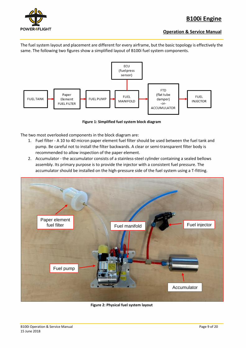
The fuel system layout and placement are different for every airframe, but the basic topology is effectively the same. The following two figures show a simplified layout of B100i fuel system components.
Figure 1: Simplified fuel system block diagram
The two most overlooked components in the block diagram are:
1. Fuel filter - A 10 to 40 micron paper element fuel filter should be used between the fuel tank and
pump. Be careful not to install the filter backwards. A clear or semi-transparent filter body is
recommended to allow inspection of the paper element.
2. Accumulator - the accumulator consists of a stainless-steel cylinder containing a sealed bellows
assembly. Its primary purpose is to provide the injector with a consistent fuel pressure. The
accumulator should be installed on the high-pressure side of the fuel system using a T-fitting.
Figure 2: Physical fuel system layout
Fuel injector Paper element
fuel filter Fuel manifold
Fuel pump
Accumulator
B100i Engine
Operation & Service Manual
B100i Operation & Service Manual Page 10 of 20 15 June 2018
3.7 Cooling
The B100i is an air-cooled engine. Like all engines, proper cooling is essential for maintaining engine health and performance. Air ducts or baffling systems should be tightly cowled to the head such that air is directed through the fins of each cylinder with minimal bypass. Cooling ducts can be fabricated of various materials including sheet metal, composite or even additive-manufactured plastics, but be aware that many plastics such as SLS nylon will melt if it touches the exhaust port. Adjust the geometry of your cooling ducts to provide even airflow across both cylinders and to maintain a cylinder head temperature in the appropriate range. (See Section 5.4).
4. Pre-Flight Checklist
The following pre-flight checklist relating to the engine system is suggested as a minimum.
• Exhaust mounts secure
• Air filter secure and in good condition
• Fuel filter secure and in good condition
• Fuel tank vent clear of obstruction
• Engine free from fuel and oil leaks
• Engine rotates freely
• Spark plug gap and secure cap
• High tension spark plug lead cover not damaged
• Throttle servo linkage does not contact any surrounding parts
• Throttle linkage secure
• Check propeller and spinner general condition
• Fuel lines free of kinks
• Expected RPM and CHT at wide open throttle
4.1 Exhaust mounts secure
There are two types of exhaust supplied with the B100i: the low-noise PRX exhaust and the sidemount exhaust. Please refer to the engine specification sheet to determine which exhaust has been supplied.
B100i Engine
Operation & Service Manual
B100i Operation & Service Manual Page 11 of 20 15 June 2018
Specification Torque to 50 in-lbs (5.6 N-m)
Tools Torque wrench with long reach 4mm hex bit, flashlight (stock exhaust only)
Explanation The exhaust bolts can slowly loosen over time. As such, a pre-flight check of the bolt torques is recommended to maintain gasket clamp pressure and prevent exhaust damage. Loose bolts transfer much of the torsional vibration of the engine to the remaining exhaust mounts on the crankcase and may ultimately crack the exhaust mounts or the crankcase. In addition, loose bolts may vibrate within the cylinder head and damage the threads on the cylinder head.
Note: Set torque wrench to 50 in-lbs and note how much the screw turns before the torque is achieved. All exhausts have two header screws that are accessible via thru-holes in the exhaust body, with the exception of one of the stock exhausts that only provides one access hole through the body. In that instance, the other header screw is accessed through the exhaust opening itself. You may need a flashlight to locate the screw head.
4.2 Air filter secure and in good condition
Specification Air filter is secure with minimal dirt or debris and no holes or tears
Explanation The air filter prevents dirt and debris entering the engine. Over time the air filter will clog up and then restrict the air flow entering the combustion chamber. The time interval for changing the air filter will depend heavily on the operating environment. The air filter should be visibly inspected prior to each flight. The filter should be secure and there should be minimal dirt/debris. There should be no holes or tears in the filter. If the engine fails to meet the expected RPM during the pre-flight check, the air filter should be replaced.
4.3 Fuel filter secure and in good condition
Specification Fuel filter is secure with minimal dirt or debris and no holes or tears
Explanation The on-board fuel filter should be visibly inspected prior to each flight. The filter should be secure and there should be minimal dirt/debris. There should be no holes or tears in the filter. If the fuel filter is clogged, the pump may be unable to make the expected fuel pressure.
4.4 Fuel tank vent clear of obstruction
Specification Cleared fuel tank vent
Explanation A clogged vent line will develop a vacuum in the fuel tank which may become significant enough to starve the fuel pump or collapse the fuel tank. It may not be until after launch that the vacuum becomes evident.
B100i Engine
Operation & Service Manual
B100i Operation & Service Manual Page 12 of 20 15 June 2018
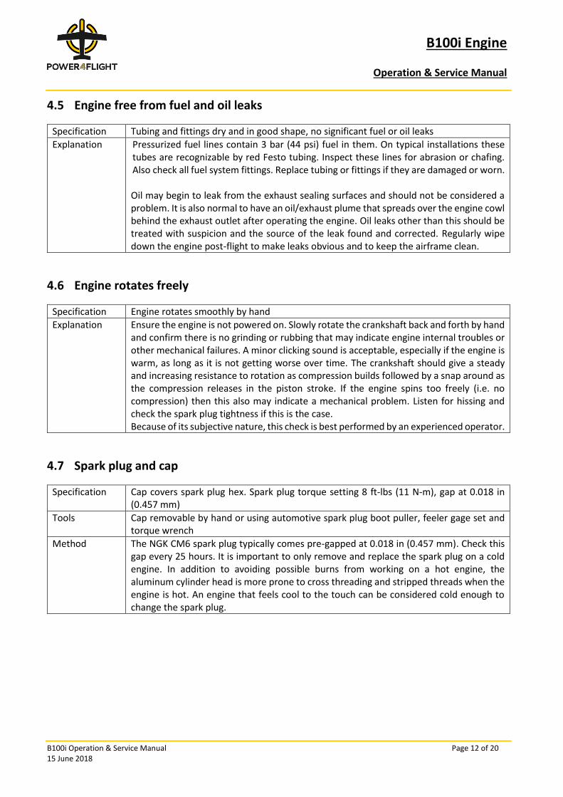
4.5 Engine free from fuel and oil leaks
Specification Tubing and fittings dry and in good shape, no significant fuel or oil leaks
Explanation Pressurized fuel lines contain 3 bar (44 psi) fuel in them. On typical installations these tubes are recognizable by red Festo tubing. Inspect these lines for abrasion or chafing. Also check all fuel system fittings. Replace tubing or fittings if they are damaged or worn. Oil may begin to leak from the exhaust sealing surfaces and should not be considered a problem. It is also normal to have an oil/exhaust plume that spreads over the engine cowl behind the exhaust outlet after operating the engine. Oil leaks other than this should be treated with suspicion and the source of the leak found and corrected. Regularly wipe down the engine post-flight to make leaks obvious and to keep the airframe clean.
4.6 Engine rotates freely
Specification Engine rotates smoothly by hand
Explanation Ensure the engine is not powered on. Slowly rotate the crankshaft back and forth by hand and confirm there is no grinding or rubbing that may indicate engine internal troubles or other mechanical failures. A minor clicking sound is acceptable, especially if the engine is warm, as long as it is not getting worse over time. The crankshaft should give a steady and increasing resistance to rotation as compression builds followed by a snap around as the compression releases in the piston stroke. If the engine spins too freely (i.e. no compression) then this also may indicate a mechanical problem. Listen for hissing and check the spark plug tightness if this is the case. Because of its subjective nature, this check is best performed by an experienced operator.
4.7 Spark plug and cap
Specification Cap covers spark plug hex. Spark plug torque setting 8 ft-lbs (11 N-m), gap at 0.018 in (0.457 mm)
Tools Cap removable by hand or using automotive spark plug boot puller, feeler gage set and torque wrench
Method The NGK CM6 spark plug typically comes pre-gapped at 0.018 in (0.457 mm). Check this gap every 25 hours. It is important to only remove and replace the spark plug on a cold engine. In addition to avoiding possible burns from working on a hot engine, the aluminum cylinder head is more prone to cross threading and stripped threads when the engine is hot. An engine that feels cool to the touch can be considered cold enough to change the spark plug.
B100i Engine
Operation & Service Manual
B100i Operation & Service Manual Page 13 of 20 15 June 2018
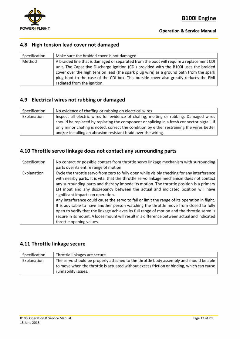
4.8 High tension lead cover not damaged
Specification Make sure the braided cover is not damaged
Method A braided line that is damaged or separated from the boot will require a replacement CDI unit. The Capacitive Discharge Ignition (CDI) provided with the B100i uses the braided cover over the high tension lead (the spark plug wire) as a ground path from the spark plug boot to the case of the CDI box. This outside cover also greatly reduces the EMI radiated from the ignition.
4.9 Electrical wires not rubbing or damaged
Specification No evidence of chaffing or rubbing on electrical wires
Explanation Inspect all electric wires for evidence of chafing, melting or rubbing. Damaged wires should be replaced by replacing the component or splicing in a fresh connector pigtail. If only minor chafing is noted, correct the condition by either restraining the wires better and/or installing an abrasion resistant braid over the wiring.
4.10 Throttle servo linkage does not contact any surrounding parts
Specification No contact or possible contact from throttle servo linkage mechanism with surrounding parts over its entire range of motion
Explanation Cycle the throttle servo from zero to fully open while visibly checking for any interference with nearby parts. It is vital that the throttle servo linkage mechanism does not contact any surrounding parts and thereby impede its motion. The throttle position is a primary EFI input and any discrepancy between the actual and indicated position will have significant impacts on operation. Any interference could cause the servo to fail or limit the range of its operation in flight. It is advisable to have another person watching the throttle move from closed to fully open to verify that the linkage achieves its full range of motion and the throttle servo is secure in its mount. A loose mount will result in a difference between actual and indicated throttle opening values.
4.11 Throttle linkage secure
Specification Throttle linkages are secure
Explanation The servo should be properly attached to the throttle body assembly and should be able to move when the throttle is actuated without excess friction or binding, which can cause runnability issues.
B100i Engine
Operation & Service Manual
B100i Operation & Service Manual Page 14 of 20 15 June 2018
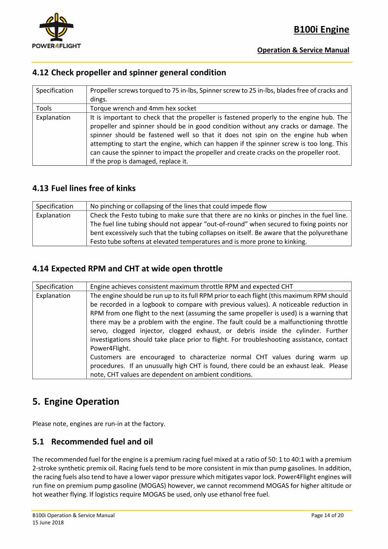
4.12 Check propeller and spinner general condition
Specification Propeller screws torqued to 75 in-lbs, Spinner screw to 25 in-lbs, blades free of cracks and dings.
Tools Torque wrench and 4mm hex socket
Explanation It is important to check that the propeller is fastened properly to the engine hub. The propeller and spinner should be in good condition without any cracks or damage. The spinner should be fastened well so that it does not spin on the engine hub when attempting to start the engine, which can happen if the spinner screw is too long. This can cause the spinner to impact the propeller and create cracks on the propeller root. If the prop is damaged, replace it.
4.13 Fuel lines free of kinks
Specification No pinching or collapsing of the lines that could impede flow
Explanation Check the Festo tubing to make sure that there are no kinks or pinches in the fuel line. The fuel line tubing should not appear “out-of-round” when secured to fixing points nor bent excessively such that the tubing collapses on itself. Be aware that the polyurethane Festo tube softens at elevated temperatures and is more prone to kinking.
4.14 Expected RPM and CHT at wide open throttle
Specification Engine achieves consistent maximum throttle RPM and expected CHT
Explanation The engine should be run up to its full RPM prior to each flight (this maximum RPM should be recorded in a logbook to compare with previous values). A noticeable reduction in RPM from one flight to the next (assuming the same propeller is used) is a warning that there may be a problem with the engine. The fault could be a malfunctioning throttle servo, clogged injector, clogged exhaust, or debris inside the cylinder. Further investigations should take place prior to flight. For troubleshooting assistance, contact Power4Flight. Customers are encouraged to characterize normal CHT values during warm up procedures. If an unusually high CHT is found, there could be an exhaust leak. Please note, CHT values are dependent on ambient conditions.
5. Engine Operation
Please note, engines are run-in at the factory.
5.1 Recommended fuel and oil
The recommended fuel for the engine is a premium racing fuel mixed at a ratio of 50: 1 to 40:1 with a premium 2-stroke synthetic premix oil. Racing fuels tend to be more consistent in mix than pump gasolines. In addition, the racing fuels also tend to have a lower vapor pressure which mitigates vapor lock. Power4Flight engines will run fine on premium pump gasoline (MOGAS) however, we cannot recommend MOGAS for higher altitude or hot weather flying. If logistics require MOGAS be used, only use ethanol free fuel.
B100i Engine
Operation & Service Manual
B100i Operation & Service Manual Page 15 of 20 15 June 2018
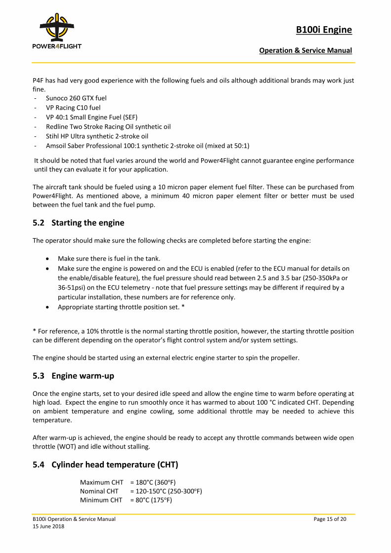
P4F has had very good experience with the following fuels and oils although additional brands may work just fine. - Sunoco 260 GTX fuel
- VP Racing C10 fuel
- VP 40:1 Small Engine Fuel (SEF)
- Redline Two Stroke Racing Oil synthetic oil
- Stihl HP Ultra synthetic 2-stroke oil
- Amsoil Saber Professional 100:1 synthetic 2-stroke oil (mixed at 50:1)
It should be noted that fuel varies around the world and Power4Flight cannot guarantee engine performance until they can evaluate it for your application. The aircraft tank should be fueled using a 10 micron paper element fuel filter. These can be purchased from Power4Flight. As mentioned above, a minimum 40 micron paper element filter or better must be used between the fuel tank and the fuel pump.
5.2 Starting the engine
The operator should make sure the following checks are completed before starting the engine:
• Make sure there is fuel in the tank.
• Make sure the engine is powered on and the ECU is enabled (refer to the ECU manual for details on
the enable/disable feature), the fuel pressure should read between 2.5 and 3.5 bar (250-350kPa or
36-51psi) on the ECU telemetry - note that fuel pressure settings may be different if required by a
particular installation, these numbers are for reference only.
• Appropriate starting throttle position set. *
* For reference, a 10% throttle is the normal starting throttle position, however, the starting throttle position can be different depending on the operator’s flight control system and/or system settings. The engine should be started using an external electric engine starter to spin the propeller.
5.3 Engine warm-up
Once the engine starts, set to your desired idle speed and allow the engine time to warm before operating at high load. Expect the engine to run smoothly once it has warmed to about 100 °C indicated CHT. Depending on ambient temperature and engine cowling, some additional throttle may be needed to achieve this temperature. After warm-up is achieved, the engine should be ready to accept any throttle commands between wide open throttle (WOT) and idle without stalling.
5.4 Cylinder head temperature (CHT)
Maximum CHT = 180°C (360oF) Nominal CHT = 120-150°C (250-300oF) Minimum CHT = 80°C (175oF)
B100i Engine
Operation & Service Manual
B100i Operation & Service Manual Page 16 of 20 15 June 2018
The major parameter to be aware of when operating the B100i engine is the cylinder head temperature (CHT). CHT readings above 180°C (360oF) will result in accelerated wear to the engine and may cause permanent damage to the core engine. The maximum CHT should not exceed 180°C (360oF) for a period greater than one hour. If the engine is subjected to these conditions, it should be inspected by Power4Flight to check for damage to the ring, piston and/or cylinder before returning the engine to flight worthy status. If the CHT reading exceeds 210°C (410oF), assume the engine is damaged and return the engine to Power4Flight for inspection. A properly integrated B100i should maintain CHT between 120-150°C (250-300oF) in most operating environments. CHT readings may fluctuate between 60°C (140oF) and 180°C (360oF) during operation. If the engine experiences extended operation at or outside these numbers the cooling system should be adjusted to maintain a nominal CHT between 120-150°C (250-300oF). CHT readings below 80°C (175 oF) reduce the idle quality of the engine and make it more susceptible to stalling under sudden load changes.
5.5 Aircraft crash or severe propeller strike
If the engine has been involved in a crash or a severe propeller strike, it is recommended that it be fully inspected by a Power4Flight trained person or returned to Power4Flight for assessment.
6. Service items
The B100i is designed to require minimal maintenance. A comprehensive pre-flight checklist will identify any engine components requiring attention. In addition to pre-flight checks, it is recommended that the following service items be completed at the intervals specified. These tasks can be completed by an experienced operator.
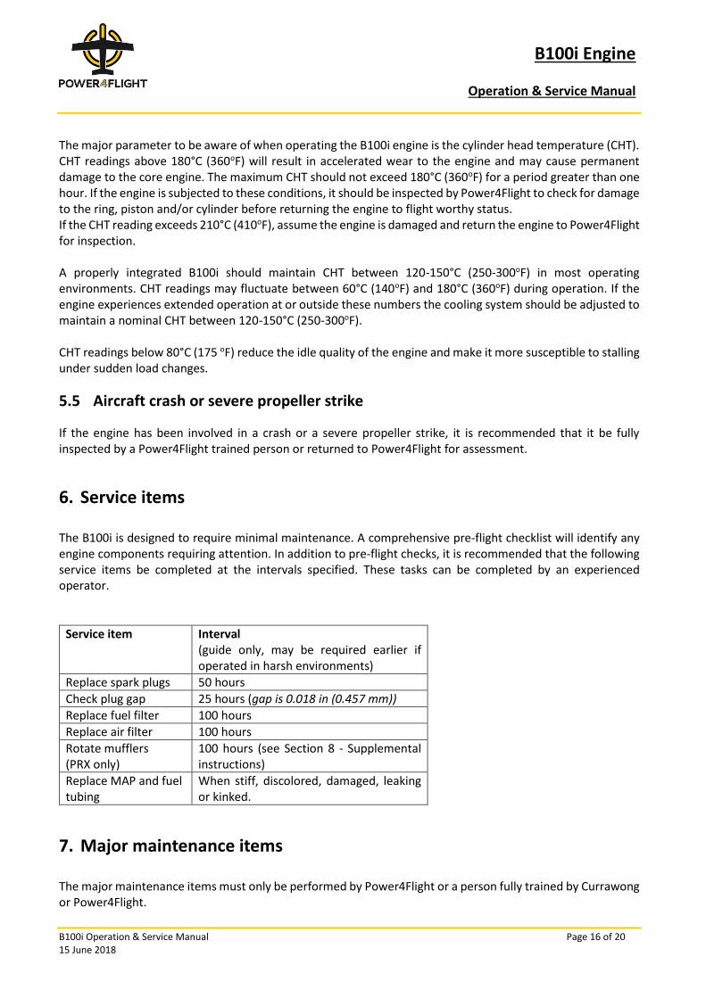
Service item Interval (guide only, may be required earlier if operated in harsh environments)
Replace spark plugs 50 hours
Check plug gap 25 hours (gap is 0.018 in (0.457 mm))
Replace fuel filter 100 hours
Replace air filter 100 hours
Rotate mufflers (PRX only)
100 hours (see Section 8 - Supplemental instructions)
Replace MAP and fuel tubing
When stiff, discolored, damaged, leaking or kinked.
7. Major maintenance items
The major maintenance items must only be performed by Power4Flight or a person fully trained by Currawong or Power4Flight.
B100i Engine
Operation & Service Manual
B100i Operation & Service Manual Page 17 of 20 15 June 2018
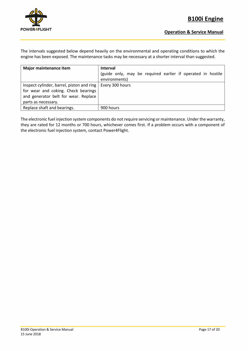
The intervals suggested below depend heavily on the environmental and operating conditions to which the engine has been exposed. The maintenance tasks may be necessary at a shorter interval than suggested.
Major maintenance item Interval (guide only, may be required earlier if operated in hostile environments)
Inspect cylinder, barrel, piston and ring for wear and coking. Check bearings and generator belt for wear. Replace parts as necessary.
Every 300 hours
Replace shaft and bearings. 900 hours
The electronic fuel injection system components do not require servicing or maintenance. Under the warranty, they are rated for 12 months or 700 hours, whichever comes first. If a problem occurs with a component of the electronic fuel injection system, contact Power4Flight.

B100i Engine
Operation & Service Manual
B100i Operation & Service Manual Page 18 of 20 15 June 2018
8. Supplemental instructions
8.1 100-hour PRX muffler rotation (if equipped)
Each PRX muffler attaches using two header screws in the cylinder and two additional screws that secure the muffler to a support bracket on the engine mount. These attachment points are high-stress areas. To spread out the loads over the life of the muffler, the mufflers should be rotated (swapped left to right) every 100 hours of engine operation.
Specification 100 hour PRX muffler rotation
Tools 3mm ball-end long-reach hex bit, 4mm long-reach hex bit, torque wrench, M5 thread chaser
Materials (See Figure 3)
Item Reference PN
M4x8 socket-head cap screw, mount (4) McMaster 91290A140
M5x20 socket-head cap screw, header (4) McMaster 91290A242
M5 316SS split washer, header (4) McMaster 92153A422
No. 10 316SS flat washer, header (4) McMaster 90107A011
Gasket set, header (2) ZCAX0011
Primer/degreaser Loctite 7471
Threadlocker, high temp Loctite 2422
Figure 3: PRX attach hardware
B100i Engine
Operation & Service Manual
B100i Operation & Service Manual Page 19 of 20 15 June 2018
8.1.1 Procedure
1) Move engine to a dust-free location and allow the engine to cool completely. Make sure the engine
is disabled.
2) Rotate the engine slowly by hand to the peak of compression (approximately top dead center). This
ensures the exhaust port is closed by the piston, reducing the potential for FOD contamination inside
the cylinder.
3) Using the 3mm ball-end long-reach hex bit, remove the two screws from each muffler tab. Leave the
tab attached to the engine mount.
4) Using the 4mm long-reach hex bit, loosen the two header screws completely on one muffler and
carefully lift muffler off the cylinder. Repeat on opposite muffler. Be careful to keep track of which
muffler is left and right as they are removed; they are identical.
5) Remove all screws and washers from each muffler. There are two washers in each mounting hole.
Make sure all washers and screws are removed and accounted for. If a flat washer is stuck inside the
muffler, a small flat head screwdriver can be inserted through the bottom to pry off the washer.
6) Remove gasket material from the exhaust ports and muffler, being careful to keep debris from falling
into exhaust port.
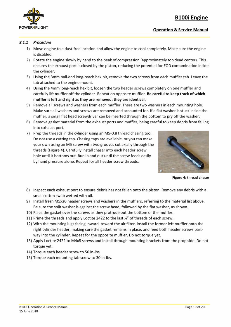
7) Prep the threads in the cylinder using an M5-0.8 thread chasing tool.
Do not use a cutting tap. Chasing taps are available, or you can make
your own using an M5 screw with two grooves cut axially through the
threads (Figure 4). Carefully install chaser into each header screw
hole until it bottoms out. Run in and out until the screw feeds easily
by hand pressure alone. Repeat for all header screw threads.
Figure 4: thread chaser
8) Inspect each exhaust port to ensure debris has not fallen onto the piston. Remove any debris with a
small cotton swab wetted with oil.
9) Install fresh M5x20 header screws and washers in the mufflers, referring to the material list above.
Be sure the split washer is against the screw head, followed by the flat washer, as shown.
10) Place the gasket over the screws as they protrude out the bottom of the muffler.
11) Prime the threads and apply Loctite 2422 to the last ¼” of threads of each screw.
12) With the mounting lugs facing inward, toward the air filter, install the former left muffler onto the
right cylinder header, making sure the gasket remains in place, and feed both header screws part-
way into the cylinder. Repeat for the opposite muffler. Do not torque yet.
13) Apply Loctite 2422 to M4x8 screws and install through mounting brackets from the prop side. Do not
torque yet.
14) Torque each header screw to 50 in-lbs.
15) Torque each mounting tab screw to 30 in-lbs.

B100i Engine
Operation & Service Manual
B100i Operation & Service Manual Page 20 of 20 15 June 2018
9. Document History
Date Editor Version summary
Mar 2018 JN First article Preliminary for B100i using B29 starting point
Jun 2018 MJ Formatting; revisions and updates based on FAR33