Embed Size (px)
Citation preview
The�results�in�this�report�apply�only�to�the�specimen�that�was�tested.�NRC�does�not�represent�that�the�results�in�this�report�apply�to�any�other�specimen.�
B3484.3� Page�1�of�4� �
Client:� Skyfold�Custom�Powerlift�Partitions,�Railtech�Ltd.�Specimen:� Skyfold�Classic�“4E”�
Specimen�ID:� B3484�32W�
Construction�Dates:� August�19,�2010�to�August�20,�2010�
�
Specimen�Description:�The�specimen�B3484�32W�was�identified�by�the�client�as�a�Skyfold�Classic�operable�partition,�with�panels,�seals,�and�clearances�in�configuration�“4E”.��The�Skyfold�Classic�operable�partition�was�installed�by�the�client�and�consisted�of�8�panels,�mounted�to�a�lifting�mechanism�that�was�supported�from�the�top.��Four�panels�were�installed�on�each�side�of�the�mechanism.��The�overall�dimensions�of�the�partition,�including�seals,�were�3508�mm�wide�by�2172�mm�high.��The�overall�thickness�of�the�partition�was�299�mm.��The�client�reported�that�each�panel�consisted�of�an�honeycomb�cellulose�core�between�a�fabric�covered�perforated�steel�plate�on�the�outer�face,�and�a�backer�plate�of�sheet�steel�on�the�inner�face.��The�steel�core�steel�part�of�each�panel�was�19�mm�thick,�3457�mm�wide�and�510�mm�high.��The�inside�surface�of�each�panel�had�a�layer�of�38�mm�fiberglass�duct�liner.��Each�panel�had�lined�rubber�“end”�seals�on�the�vertical�edges�that�retracted�and�extended�for�operation.��The�width�of�these�vertical�end�seals�when�fully�extended�was�nominally�25�mm.��All�panels�sealed�to�each�other�with�horizontal�“lip”�seals�that�compressed�a�strip�of�foam�when�the�partition�was�closed.��The�top�panel�sealed�to�the�header�with�a�lined�extruded�rubber�“bulb”�seal�57�mm�high.��The�bottom�panel�sealed�to�the�floor�with�a�lined�extruded�rubber�“bulb”�seal�57�mm�high.��The�total�mass�of�all�8�panels�including�seals�was�229.9�kg.��The�total�mass�of�the�specimen�was�342.7�kg.��Proprietary�details�of�the�specimen�are�withheld�from�this�report�at�the�request�of�the�client.��The�size�of�the�2.44�m�by�3.66�m�facility�test�opening�was�reduced�to�accommodate�the�specimen�by�constructing�a�filler�element�as�follows:��A�header�consisting�of�a�steel�beam�(C12�x�20.7)�measuring�77�mm�x�305�mm�x�3667�mm�covered�on�both�sides�with�2�layers�of�plywood�with�dimensions�of�19�mm�x�305�mm�x�3667�mm�and�6�layers�of�CGC�SHEETROCK�gypsum�panels�with�dimensions�of�16�mm�x�305�mm�x�3667�mm�was�constructed.��The�header�housed�the�motor�and�other�operable�parts�of�the�lifting�mechanism.�The�header�assembly�was�supported�at�each�end�by�39�mm�x�89�mm�wood�studs�2439�mm�long�and�spaced�89�mm�apart�and�fastened�to�the�test�frame�using�Type�S�screws�51�mm�long�spaced�every�200�mm�on�centre.�The�space�between�the�studs,�which�measured�39�mm�x�89�mm,�was�filled�with�fiberglass�insulation�and�the�supports�were�then�enclosed�with�2�layers�of�16�mm�CGC�SHEETROCK�gypsum�board�on�the�face�and�sides.��The�supports�had�a�finished�measurement�of�76�mm�deep�x�380�mm�wide�and�2362�mm�high.��2�strips�of�a�single�layer�of�CGC�Type�X�gypsum�board�each�measuring��16�mm�x�189�mm�x�3581�mm�were�placed�on�the�bottom�portion�of�the�test�frame.��Exposed�joints�between�pieces�of�gypsum�board�were�caulked�and�covered�with�metal�foil�tape.����
The�results�in�this�report�apply�only�to�the�specimen�that�was�tested.�NRC�does�not�represent�that�the�results�in�this�report�apply�to�any�other�specimen.�
B3484.3� Page�2�of�4� �
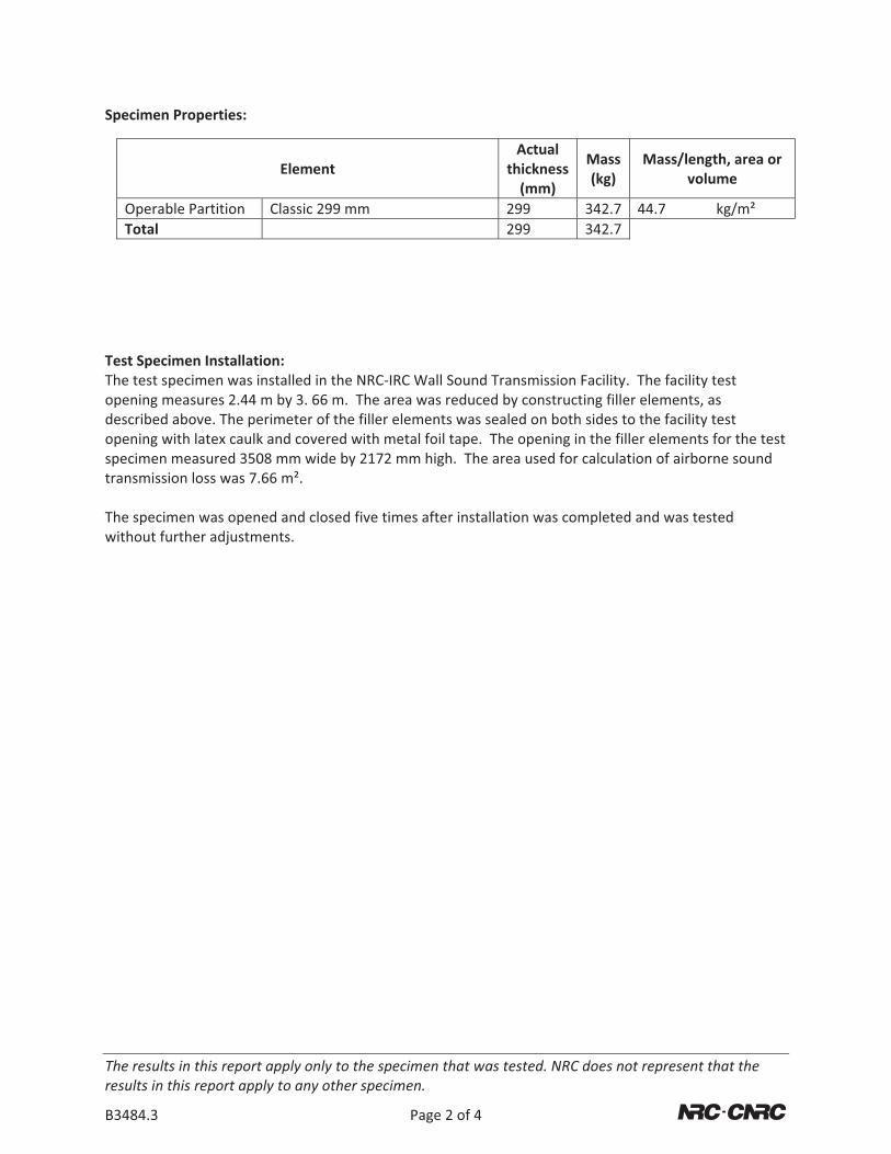
Specimen�Properties:�� � � �
�Element�
Actual�thickness(mm)�
Mass�(kg)�
Mass/length,�area�or�volume�
� Operable�Partition� Classic�299�mm� 299� 342.7 44.7� kg/m²�� Total� � 299� 342.7 � ��
��
�
Test�Specimen�Installation:�The�test�specimen�was�installed�in�the�NRC�IRC�Wall�Sound�Transmission�Facility.��The�facility�test�opening�measures�2.44�m�by�3.�66�m.��The�area�was�reduced�by�constructing�filler�elements,�as�described�above.�The�perimeter�of�the�filler�elements�was�sealed�on�both�sides�to�the�facility�test�opening�with�latex�caulk�and�covered�with�metal�foil�tape.��The�opening�in�the�filler�elements�for�the�test�specimen�measured�3508�mm�wide�by�2172�mm�high.��The�area�used�for�calculation�of�airborne�sound�transmission�loss�was�7.66�m².��The�specimen�was�opened�and�closed�five�times�after�installation�was�completed�and�was�tested�without�further�adjustments.���
� �
C
S
Te
D
L
S
MH
RLS
F
The�resultresults�in�
B3484.3�
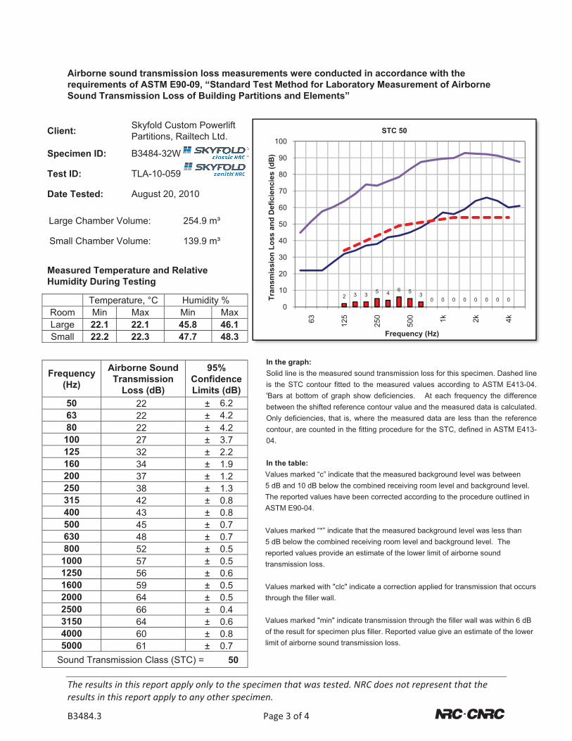
Airborne requiremSound Tr
lient:
pecimen ID:
est ID:
Date Tested:
Large Chambe
Small Chambe
Measured Temumidity Duri
TemRoom MinLarge 22.1Small 22.2
requency (Hz)
50 63 80 100 125 160 200 250 315 400 500 630 800
1000 1250 1600 2000 2500 3150 4000 5000
Sound Trans
ts�in�this�repothis�report�ap
sound transents of ASTM
ransmission
SkyfoldPartitio
B3484-
TLA-10
August
er Volume:
er Volume:
mperature aning Testing
mperature, °CMax
1 22.1 2 22.3
Airborne SoTransmissi
Loss (dB22 22 22 27 32 34 37 38 42 43 45 48 52 57 56 59 64 66 64 60 61
smission Clas
ort�apply�only�pply�to�any�ot
smission losM E90-09, “SLoss of Bui
d Custom Powns, Railtech L
-32W
0-059
20, 2010
254.9 m
139.9 m
nd Relative
HumiditMin45.8 47.7
oundion
B)
95ConfiLimit
±±±±±±±±±±±±±±±±±±±±±
ss (STC) =
to�the�specimther�specimen
P
s measuremStandard Teslding Partitio
werliftLtd.
ISi'bOc0
IV5TA
V5rt
Vt
Voli
m³
m³
y %Max46.1 48.3
5%idence ts (dB)
6.24.24.23.72.21.91.21.30.80.80.70.70.50.50.60.50.50.40.60.80.7
50
men�that�was�n.�
Page�3�of�4
ments were cost Method forons and Elem
In the graph: Solid line is the ms the STC contoBars at bottom between the shiftOnly deficienciescontour, are cou04.
In the table:Values marked “c5 dB and 10 dB bThe reported valuASTM E90-04.
Values marked “*5 dB below the coreported values pransmission loss
Values marked whrough the filler
Values marked "mof the result for simit of airborne s
0
10
20
30
40
50
60
70
80
90
100
63
Tran
smis
sion
Los
s an
d D
efic
ienc
ies
(dB
)
tested.�NRC�d
onducted in r Laboratoryments”
measured soundour fitted to the of graph show dted reference cos, that is, wherented in the fitting
c” indicate that thbelow the combinues have been c
*” indicate that thombined receivinprovide an estimas.
with "clc" indicatewall.
min" indicate tranpecimen plus fill
sound transmissi
2 3 3
125
250
does�not�repr
accordance y Measureme
transmission losmeasured value
deficiencies. Aontour value and the measured d
g procedure for t
he measured bacned receiving roo
corrected accordi
he measured bacng room level anate of the lower l
e a correction app
nsmission througer. Reported valuon loss.
5 4 6 5 3
250
500
Frequency (H
STC 50
resent�that�th
with the ent of Airborn
ss for this specimes according to At each frequencthe measured dadata are less thathe STC, defined
ckground level wom level and bacng to the proced
ckground level wd background lelimit of airborne s
plied for transmis
gh the filler wall wue give an estim
0 0 0 0 0
1k 2k
Hz)
he�
�
ne
men. Dashed lineASTM E413-04
cy the differenceata is calculatedan the referenced in ASTM E413-
was between ckground level.dure outlined in
was less than vel. The sound
ssion that occurs
was within 6 dB mate of the lower
0 0 0
4k
e.
e.
e-
s
APPENDIX: Airborne Sound Transmission Wall Facility
National�Research�Council�Canada��Institute�for�Research�in�Construction�Acoustics�Laboratory�1200�Montreal�Road,�Ottawa,�Ontario�K1A�0R6�Tel: 613-993-2305 Fax: 613-954-1495
The�results�in�this�report�apply�only�to�the�specimen�that�was�tested.�NRC�does�not�represent�that�the�results�in�this�report�apply�to�any�other�specimen.�
B3484.3� Page�4�of�4� �
Facility and Equipment: The acoustics test facility comprises two reverberation rooms (referred to in this report as the small and large rooms) with a moveable test frame between the two rooms. In each room, a calibrated Bruel & Kjaer condenser microphone (type 4166 or 4165) with preamp is moved under computer control to nine positions, and measurements are made in both rooms using an 8-channel National Instrument NI4472 system installed in a desktop PC-type computer. Each room has four bi-amped loudspeakers driven by separate amplifiers and noise sources. To increase randomness of the sound field, there are fixed diffusing panels in each room.
Test Procedure: Airborne sound transmission measurements were conducted in accordance with the requirements of ASTM E90-09, “Standard Method for Laboratory Measurement of Airborne Sound Transmission Loss of Building Partitions”. Airborne sound transmission loss tests were performed in the forward (receiving room is the large room) and reverse (receiving room is the small room) directions. Results presented in this report are the average of the tests in these two directions. In each case, sound transmission loss values were calculated from the average sound pressure levels of both the source and receiving rooms and the average reverberation times of the receiving room. One-third octave band sound pressure levels were measured for 32 seconds at nine microphone positions in each room and then averaged to get the average sound pressure level in each room. Five sound decays were averaged to get the reverberation time at each microphone position in the receiving room; these times were averaged to get the average reverberation times for the room. A complete description of the test procedure, information on the flanking limit of the facility and reference specimen test results are available on request.
Significance of Test Results: ASTM E90-09 requires measurements in 1/3-octave bands in the frequency range 100 Hz to 5000 Hz. Within those ranges, reproducibility has been assessed by inter-laboratory round robin studies. The standards recommend making measurements and reporting results over a larger frequency range, and this report presents such results, which may be useful for expert evaluation of the specimen performance. The precision of results outside the 100 to 5000 Hz range has not been established, but is expected to depend on laboratory-specific factors.
Sound Transmission Class (STC): was determined in accordance with ASTM E413-04, “Classification for Rating Sound Insulation”. The Sound Transmission Class (STC) is a single-figure rating scheme intended to rate the acoustical performance of a partition element separating offices or dwellings. The higher the value of the rating, the better the performance. The rating is intended to correlate with subjective impressions of the sound insulation provided against the sounds of speech, radio, television, music, and similar sources of noise characteristic of offices and dwellings. The STC is of limited use in applications involving noise spectra that differ markedly from those referred to above (for example, heavy machinery, power transformers, aircraft noise, motor vehicle noise). Generally, in such applications it is preferable to consider the source levels and insulation requirements for each frequency band.
Confidence Limits: Acoustical measurement in rooms is a sampling process and as such has associated with it a degree of uncertainty. By using enough microphone and loudspeaker positions, the uncertainty can be reduced and upper and lower limits assigned to the probable error in the measurement. These limits are called 95% confidence limits. They are calculated for each test according to the procedures in ASTM E90-09 and must be less than upper limits given in the standards. These confidence limits do not relate directly to the variation expected when a nominally identical specimen is built, installed and tested (repeatability). Nor do they relate directly to the differences expected when nominally identical specimens are tested in different laboratories (reproducibility).
In Situ Performance: Ratings obtained by this standard method tend to represent an upper limit to what might be measured in a field test, due to structure-borne transmission (“flanking”) and construction deficiencies in actual buildings.