Embed Size (px)
Citation preview
Signature Series Vehicles A4 Installation Guidelines
STāSIS Engineering
2 of 30
Table of Contents
Page Torque specs 3 Suspension
Front and Rear Suspension 4 Rear Anti-Roll Bar (Challenge Series) 11
Braking Touring Brake Kit 13 Challenge Brake Kit 17 Bed-In Procedure 22
Exhaust Exhaust Kit 23
Differentials A4 Center Differential 25
Post Installation Checklist 29
3 of 30
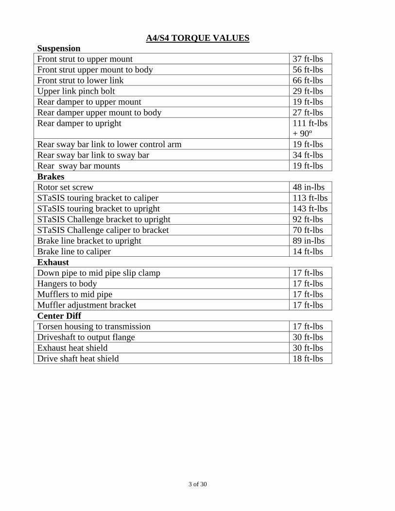
A4/S4 TORQUE VALUES Suspension Front strut to upper mount 37 ft-lbs Front strut upper mount to body 56 ft-lbs Front strut to lower link 66 ft-lbs Upper link pinch bolt 29 ft-lbs Rear damper to upper mount 19 ft-lbs Rear damper upper mount to body 27 ft-lbs Rear damper to upright 111 ft-lbs
+ 90º Rear sway bar link to lower control arm 19 ft-lbs Rear sway bar link to sway bar 34 ft-lbs Rear sway bar mounts 19 ft-lbs Brakes Rotor set screw 48 in-lbs STaSIS touring bracket to caliper 113 ft-lbsSTaSIS touring bracket to upright 143 ft-lbsSTaSIS Challenge bracket to upright 92 ft-lbs STaSIS Challenge caliper to bracket 70 ft-lbs Brake line bracket to upright 89 in-lbs Brake line to caliper 14 ft-lbs Exhaust Down pipe to mid pipe slip clamp 17 ft-lbs Hangers to body 17 ft-lbs Mufflers to mid pipe 17 ft-lbs Muffler adjustment bracket 17 ft-lbs Center Diff Torsen housing to transmission 17 ft-lbs Driveshaft to output flange 30 ft-lbs Exhaust heat shield 30 ft-lbs Drive shaft heat shield 18 ft-lbs
4 of 30
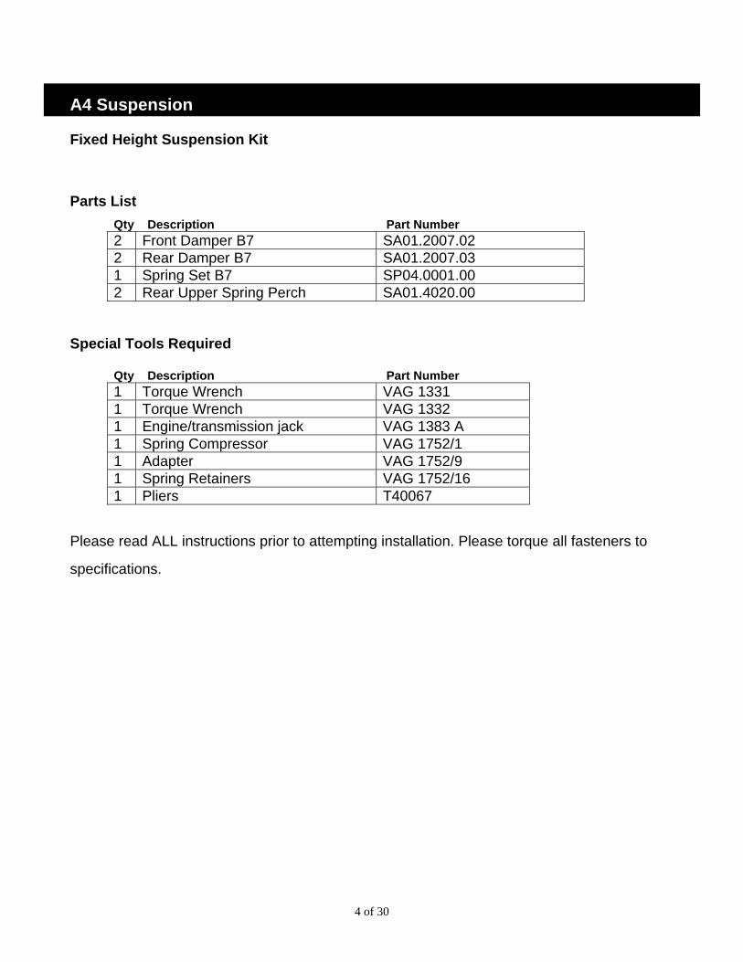
A4 Suspension Fixed Height Suspension Kit
Parts List Qty Description Part Number 2 Front Damper B7 SA01.2007.02 2 Rear Damper B7 SA01.2007.03 1 Spring Set B7 SP04.0001.00 2 Rear Upper Spring Perch SA01.4020.00
Special Tools Required
Qty Description Part Number 1 Torque Wrench VAG 1331 1 Torque Wrench VAG 1332 1 Engine/transmission jack VAG 1383 A 1 Spring Compressor VAG 1752/1 1 Adapter VAG 1752/9 1 Spring Retainers VAG 1752/16 1 Pliers T40067
Please read ALL instructions prior to attempting installation. Please torque all fasteners to
specifications.
5 of 30
Front Removal 1 Before removing any parts, park the car on a
secure, stable, and level surface and loosen (but do not remove) the wheel lug nuts. Jack the vehicle up, and place the car on four stable jack stands or use a professional vehicle lift. We recommend having two people available for certain steps of the installation.
2 Remove wheel trim; pull trim cap off light-alloy wheels (using puller in vehicle tool kit). Remove wheel
3 Before removing left suspension strut, remove headlight range control link from track control link by opening retaining clip.
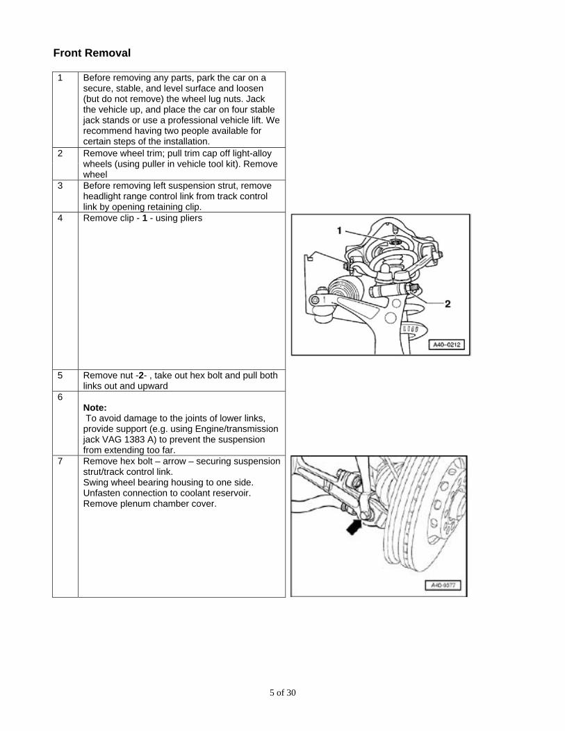
4 Remove clip - 1 - using pliers
5 Remove nut -2- , take out hex bolt and pull both links out and upward
6 Note: To avoid damage to the joints of lower links, provide support (e.g. using Engine/transmission jack VAG 1383 A) to prevent the suspension from extending too far.
7 Remove hex bolt – arrow – securing suspension strut/track control link. Swing wheel bearing housing to one side. Unfasten connection to coolant reservoir. Remove plenum chamber cover.
6 of 30
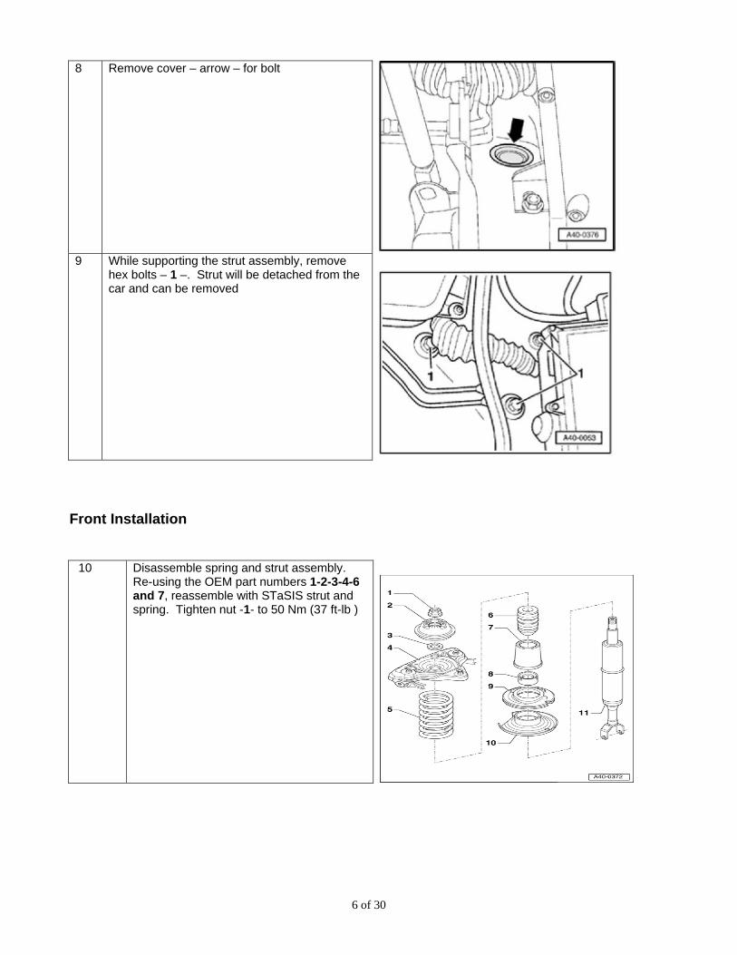
8 Remove cover – arrow – for bolt
9 While supporting the strut assembly, remove
hex bolts – 1 –. Strut will be detached from the car and can be removed
Front Installation 10 Disassemble spring and strut assembly.
Re-using the OEM part numbers 1-2-3-4-6 and 7, reassemble with STaSIS strut and spring. Tighten nut -1- to 50 Nm (37 ft-lb )
7 of 30
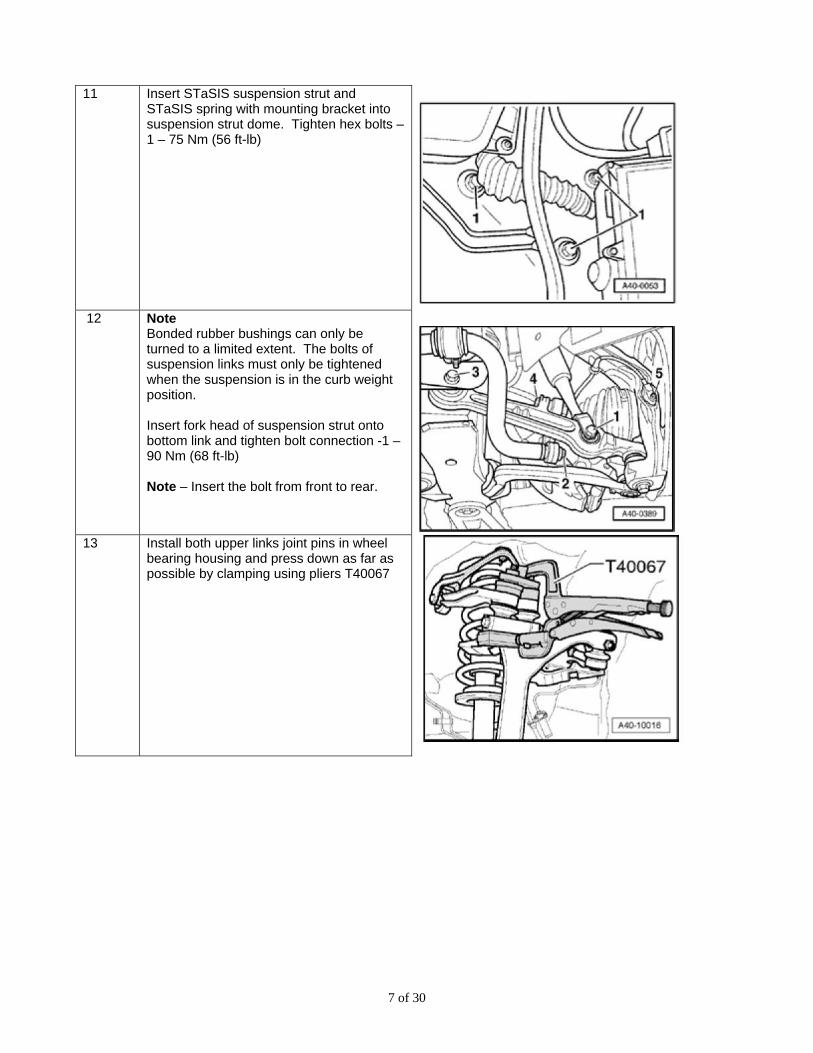
11 Insert STaSIS suspension strut and
STaSIS spring with mounting bracket into suspension strut dome. Tighten hex bolts – 1 – 75 Nm (56 ft-lb)
12 Note
Bonded rubber bushings can only be turned to a limited extent. The bolts of suspension links must only be tightened when the suspension is in the curb weight position. Insert fork head of suspension strut onto bottom link and tighten bolt connection -1 – 90 Nm (68 ft-lb) Note – Insert the bolt from front to rear.
13 Install both upper links joint pins in wheel
bearing housing and press down as far as possible by clamping using pliers T40067
8 of 30
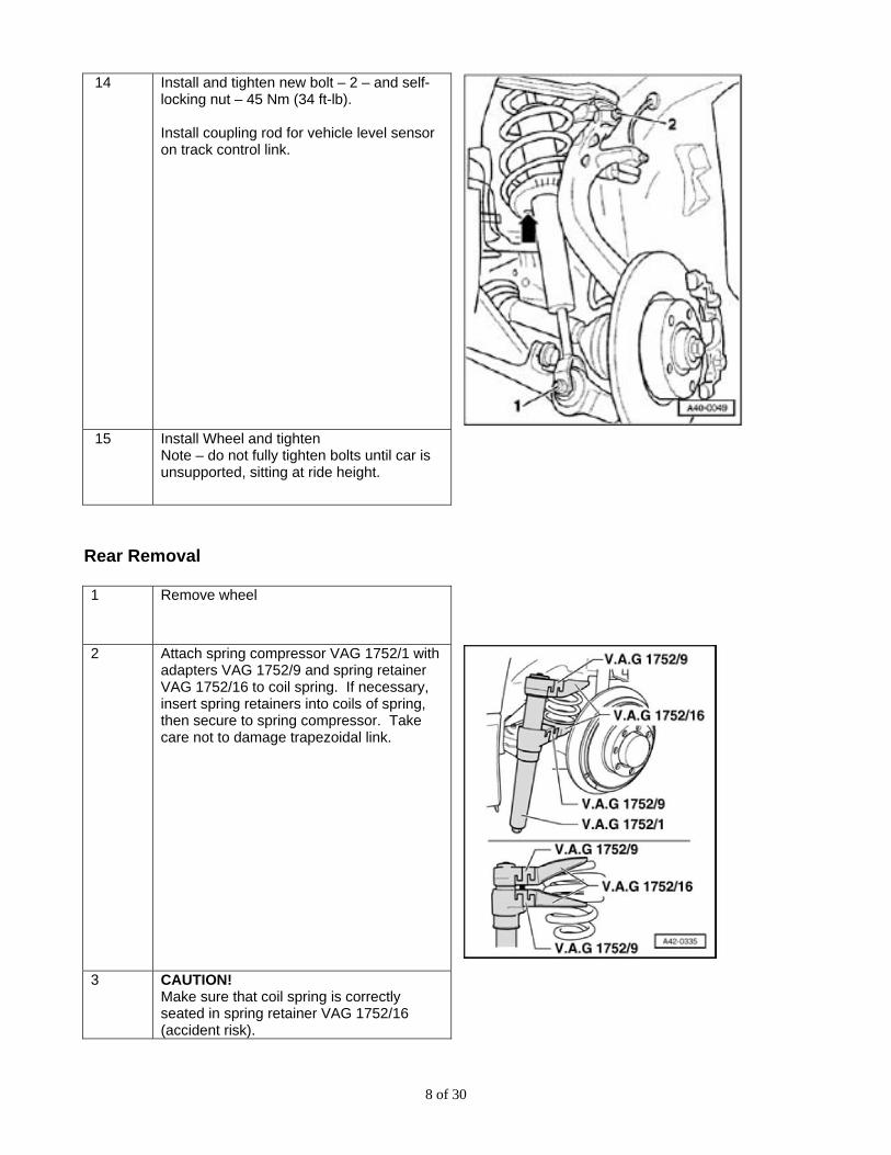
14 Install and tighten new bolt – 2 – and self-locking nut – 45 Nm (34 ft-lb). Install coupling rod for vehicle level sensor on track control link.
15 Install Wheel and tighten
Note – do not fully tighten bolts until car is unsupported, sitting at ride height.
Rear Removal 1 Remove wheel
2 Attach spring compressor VAG 1752/1 with adapters VAG 1752/9 and spring retainer VAG 1752/16 to coil spring. If necessary, insert spring retainers into coils of spring, then secure to spring compressor. Take care not to damage trapezoidal link.
3 CAUTION!
Make sure that coil spring is correctly seated in spring retainer VAG 1752/16 (accident risk).
9 of 30
4 Tighten spring compressor as far as it will go and take out spring.
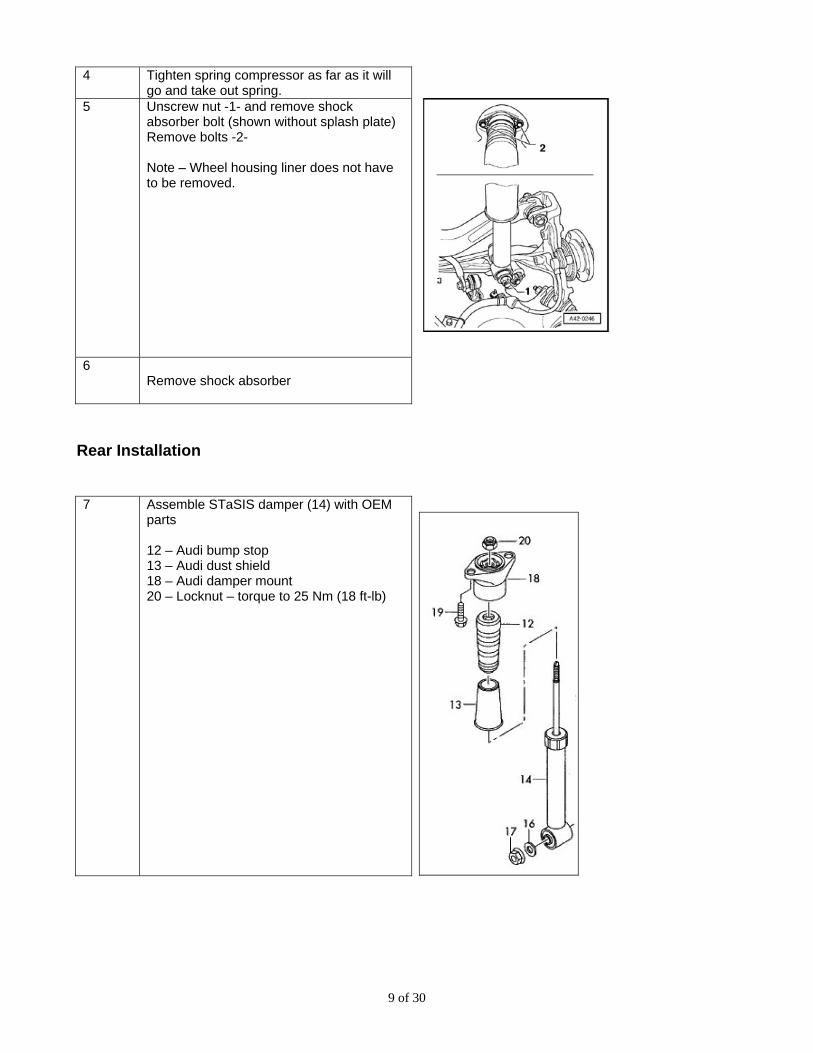
5 Unscrew nut -1- and remove shock absorber bolt (shown without splash plate) Remove bolts -2- Note – Wheel housing liner does not have to be removed.
6 Remove shock absorber
Rear Installation 7 Assemble STaSIS damper (14) with OEM
parts 12 – Audi bump stop 13 – Audi dust shield 18 – Audi damper mount 20 – Locknut – torque to 25 Nm (18 ft-lb)
10 of 30
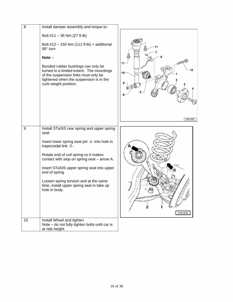
8 Install damper assembly and torque to:
Bolt #11 – 36 Nm (27 ft-lb) Bolt #12 – 150 Nm (111 ft-lb) + additional 90° turn Note – Bonded rubber bushings can only be turned to a limited extent. The mountings of the suspension links must only be tightened when the suspension is in the curb weight position.
9 Install STaSIS rear spring and upper spring seat Insert lower spring seat pin -1- into hole in trapezoidal link -2-. Rotate end of coil spring so it makes contact with stop on spring seat – arrow A. Insert STaSIS upper spring seat into upper end of spring Loosen spring tension and at the same time, install upper spring seat in take up hole in body.
10 Install Wheel and tighten
Note – do not fully tighten bolts until car is at ride height.
11 of 30
A4 Suspension Rear Anti-Roll Bar (Challenge Series Only)
Parts List
1 B7 Rear anti-roll bar SA15.1003.00 Special Tools Required
1 Torque Wrench VAG 1331
Please read ALL instructions prior to attempting installation. Please torque all fasteners to
specifications.
12 of 30
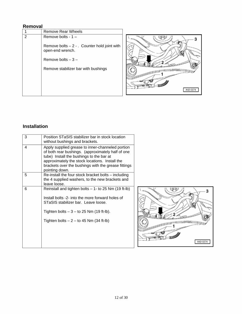
Removal 1 Remove Rear Wheels 2 Remove bolts - 1 –
Remove bolts – 2 - . Counter hold joint with open-end wrench. Remove bolts – 3 – Remove stabilizer bar with bushings
Installation 3 Position STaSIS stabilizer bar in stock location
without bushings and brackets.
4 Apply supplied grease to inner-channeled portion of both rear bushings. (approximately half of one tube) Install the bushings to the bar at approximately the stock locations. Install the brackets over the bushings with the grease fittings pointing down.
5 Re-install the four stock bracket bolts – including the 4 supplied washers, to the new brackets and leave loose.
6 Reinstall and tighten bolts – 1- to 25 Nm (19 ft-lb) Install bolts -2- into the more forward holes of STaSIS stabilizer bar. Leave loose. Tighten bolts – 3 – to 25 Nm (19 ft-lb). Tighten bolts – 2 – to 45 Nm (34 ft-lb)
13 of 30
A4 Brakes Touring Brake Kit Parts List: Qty Description Part Number
1 Rotor Alcon 349x28 RH BR01.1027.01 Assembly
1 Rotor Alcon 349x28 LH BR01.1026.01 Assembly
1 A4 Touring Bracket RH BR04.1014.00 1 A4 Touring Bracket LH BR04.1015.00 1 Modified Dust Shield RH BR07.3011.00 1 Modified Dust Shield LH BR07.3010.00 2 A4 Lowhead SHCS Torx BR04.0000.00 2 DIN Washer HA02.0611.00 4 M14 Wedge Lock Washer HA02.1400.00 6 SHCS M14x1.5x30 Zinc HA04.0002.00
Special Tools Required
Qty Description 1 T30 Torx bit 1 T55 Torx bit 1 Brake pad spreader
Installation Guidelines • The brackets are side-specific, labeled “L” for driver side and “R” for passenger side • The rotors are side-specific, rotational direction is labeled
• Torque all fasteners to specification. Do not use impact wrench.
• Ensure all ABS sensor and Pad wear sensor plugs are reconnected.
• Drive the car at low speeds for a few miles to check brake operation before starting bedding procedure. • During bedding do not thermally shock the rotors with aggressive braking before the rotors have come
up to temperature. Cracks on new rotors can form due to thermal shock. Gradually increase brake pressures as instructed in the bedding procedure.
• After bedding brakes re-torque wheel nuts to proper torque specifications. • If vibration occurs during normal usage, check for abnormal pad wear deposits on the rotor. Double
check all fasteners and repeat the bedding process 2-3 cycles until the pad deposits on the rotor becomes uniform.
14 of 30
Instructions
1 Sort the parts in the brake kit for the right and left side.
Brake bleeders face upward. Caliper mounting brackets are NOT universal.
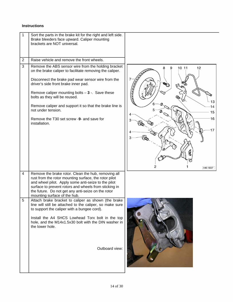
2 Raise vehicle and remove the front wheels. 3 Remove the ABS sensor wire from the holding bracket
on the brake caliper to facilitate removing the caliper. Disconnect the brake pad wear sensor wire from the driver’s side front brake inner pad. Remove caliper mounting bolts – 3 -. Save these bolts as they will be reused. Remove caliper and support it so that the brake line is not under tension. Remove the T30 set screw -9- and save for installation.
4 Remove the brake rotor. Clean the hub, removing all
rust from the rotor mounting surface, the rotor pilot and wheel pilot. Apply some anti-seize to the pilot surface to prevent rotors and wheels from sticking in the future. Do not get any anti-seize on the rotor mounting surface of the hub.
5 Attach brake bracket to caliper as shown (the brake line will still be attached to the caliper, so make sure to support the caliper with a bungee cord). Install the A4 SHCS Lowhead Torx bolt in the top hole, and the M14x1.5x30 bolt with the DIN washer in the lower hole.
Outboard view:
15 of 30
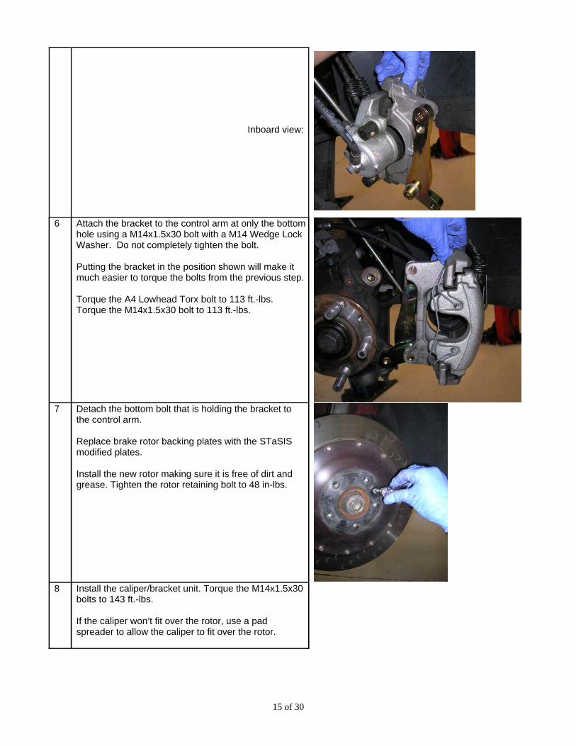
Inboard view:
6 Attach the bracket to the control arm at only the bottom hole using a M14x1.5x30 bolt with a M14 Wedge Lock Washer. Do not completely tighten the bolt. Putting the bracket in the position shown will make it much easier to torque the bolts from the previous step. Torque the A4 Lowhead Torx bolt to 113 ft.-lbs. Torque the M14x1.5x30 bolt to 113 ft.-lbs.
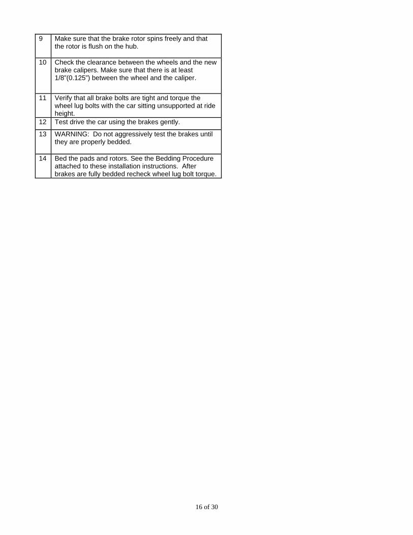
7 Detach the bottom bolt that is holding the bracket to
the control arm. Replace brake rotor backing plates with the STaSIS modified plates. Install the new rotor making sure it is free of dirt and grease. Tighten the rotor retaining bolt to 48 in-lbs.
8 Install the caliper/bracket unit. Torque the M14x1.5x30
bolts to 143 ft.-lbs. If the caliper won’t fit over the rotor, use a pad spreader to allow the caliper to fit over the rotor.
16 of 30
9 Make sure that the brake rotor spins freely and that the rotor is flush on the hub.
10 Check the clearance between the wheels and the new brake calipers. Make sure that there is at least 1/8”(0.125”) between the wheel and the caliper.
11 Verify that all brake bolts are tight and torque the wheel lug bolts with the car sitting unsupported at ride height.
12 Test drive the car using the brakes gently.
13 WARNING: Do not aggressively test the brakes until they are properly bedded.
14 Bed the pads and rotors. See the Bedding Procedure attached to these installation instructions. After brakes are fully bedded recheck wheel lug bolt torque.
17 of 30
A4 Brakes
Challenge Brake Kit
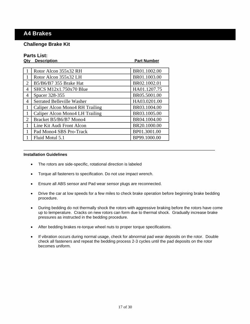
Parts List: Qty Description Part Number
1 Rotor Alcon 355x32 RH BR01.1002.00 1 Rotor Alcon 355x32 LH BR01.1003.00 2 B5/B6/B7 355 Brake Hat BR02.1002.01 4 SHCS M12x1.750x70 Blue HA01.1207.75 4 Spacer 328-355 BR05.5001.00 4 Serrated Belleville Washer HA03.0201.00 1 Caliper Alcon Mono4 RH Trailing BR03.1004.00 1 Caliper Alcon Mono4 LH Trailing BR03.1005.00 2 Bracket B5/B6/B7 Mono4 BR04.1004.00 1 Line Kit Audi Front Alcon BR20.1000.00 1 Pad Mono4 SBS Pro-Track BP01.3001.00 1 Fluid Motul 5.1 BP99.1000.00
Installation Guidelines
• The rotors are side-specific, rotational direction is labeled
• Torque all fasteners to specification. Do not use impact wrench.
• Ensure all ABS sensor and Pad wear sensor plugs are reconnected.
• Drive the car at low speeds for a few miles to check brake operation before beginning brake bedding procedure.
• During bedding do not thermally shock the rotors with aggressive braking before the rotors have come
up to temperature. Cracks on new rotors can form due to thermal shock. Gradually increase brake pressures as instructed in the bedding procedure.
• After bedding brakes re-torque wheel nuts to proper torque specifications. • If vibration occurs during normal usage, check for abnormal pad wear deposits on the rotor. Double
check all fasteners and repeat the bedding process 2-3 cycles until the pad deposits on the rotor becomes uniform.
18 of 30
Instructions
1 Sort the parts in the brake kit for the right and left side. Brake bleeders face upward. Caliper mounting brackets are universal. Install brake pads in calipers, and the lines onto the caliper as shown
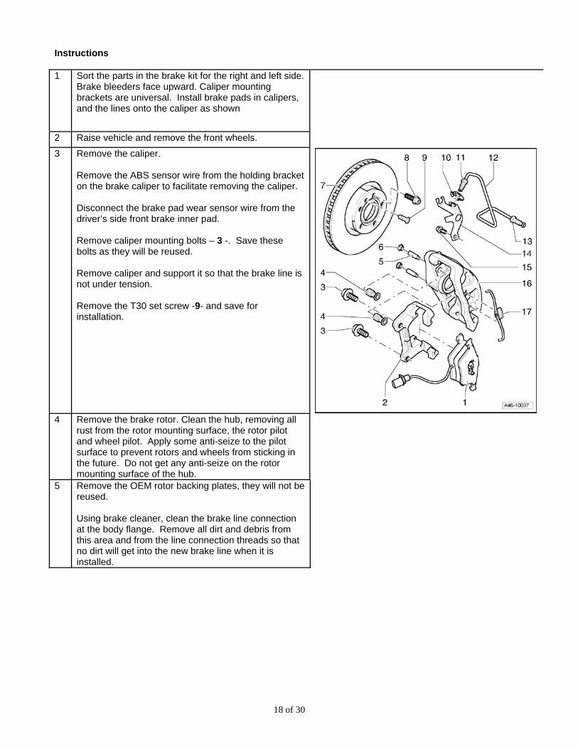
2 Raise vehicle and remove the front wheels. 3 Remove the caliper.
Remove the ABS sensor wire from the holding bracket on the brake caliper to facilitate removing the caliper. Disconnect the brake pad wear sensor wire from the driver’s side front brake inner pad. Remove caliper mounting bolts – 3 -. Save these bolts as they will be reused. Remove caliper and support it so that the brake line is not under tension. Remove the T30 set screw -9- and save for installation.
4 Remove the brake rotor. Clean the hub, removing all
rust from the rotor mounting surface, the rotor pilot and wheel pilot. Apply some anti-seize to the pilot surface to prevent rotors and wheels from sticking in the future. Do not get any anti-seize on the rotor mounting surface of the hub.
5 Remove the OEM rotor backing plates, they will not be reused. Using brake cleaner, clean the brake line connection at the body flange. Remove all dirt and debris from this area and from the line connection threads so that no dirt will get into the new brake line when it is installed.
19 of 30
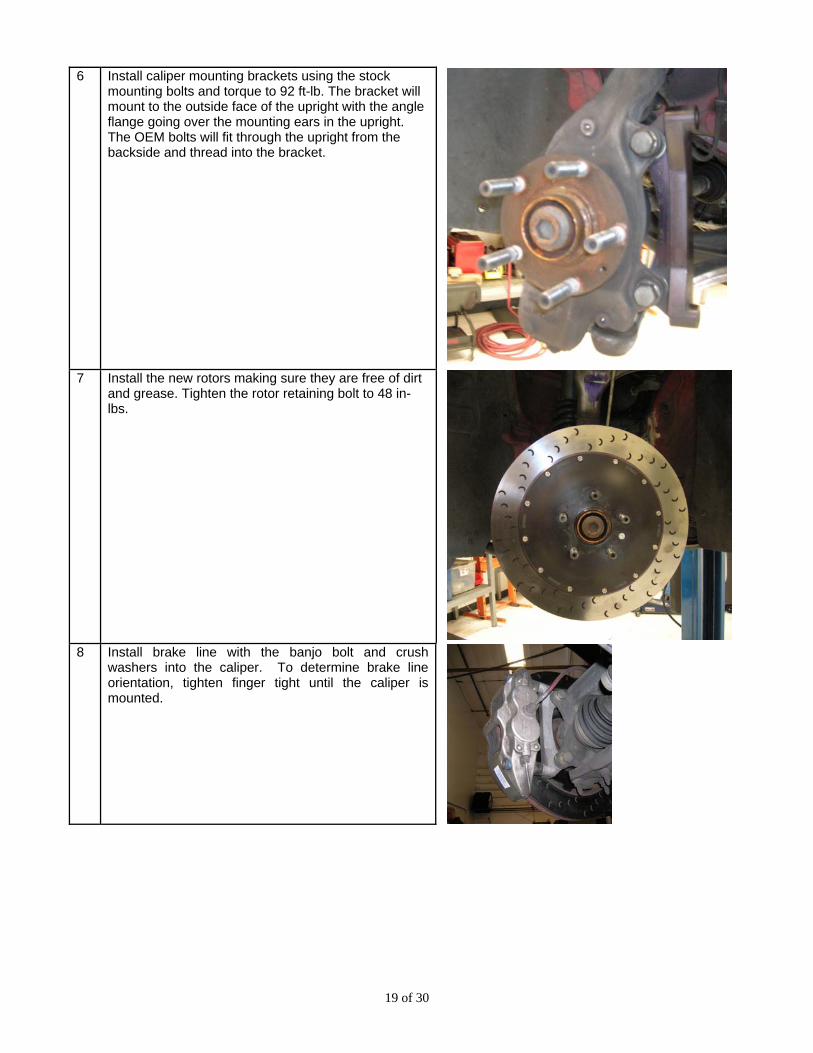
6 Install caliper mounting brackets using the stock mounting bolts and torque to 92 ft-lb. The bracket will mount to the outside face of the upright with the angle flange going over the mounting ears in the upright. The OEM bolts will fit through the upright from the backside and thread into the bracket.
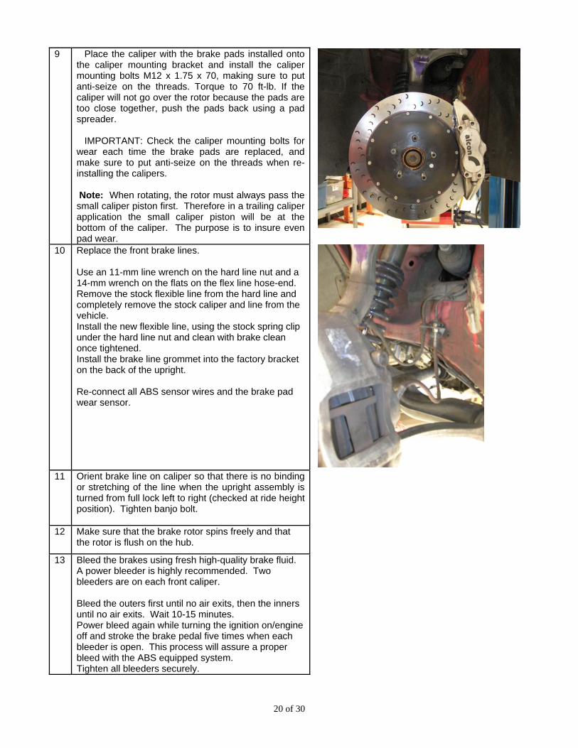
7 Install the new rotors making sure they are free of dirt
and grease. Tighten the rotor retaining bolt to 48 in-lbs.
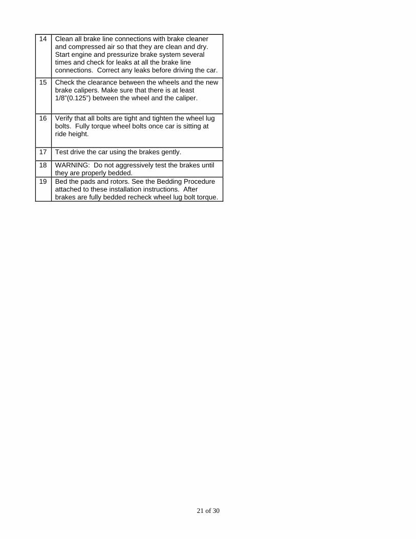
8 Install brake line with the banjo bolt and crush
washers into the caliper. To determine brake line orientation, tighten finger tight until the caliper is mounted.
20 of 30
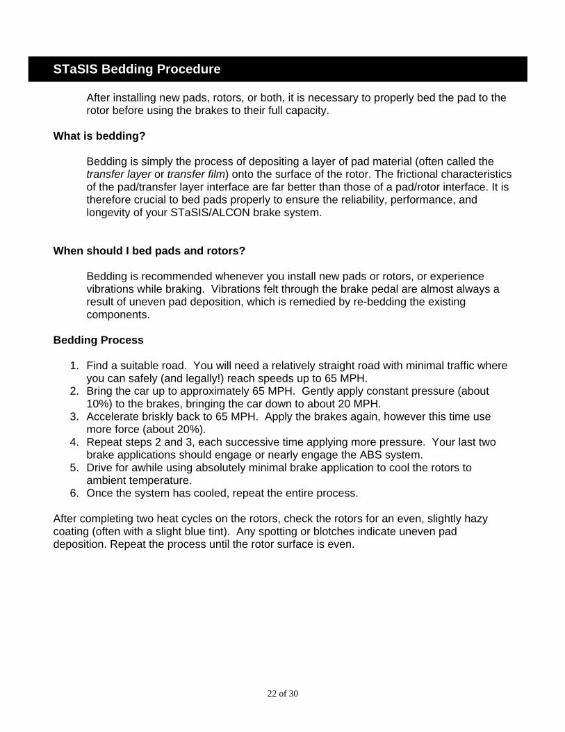
9 Place the caliper with the brake pads installed onto the caliper mounting bracket and install the caliper mounting bolts M12 x 1.75 x 70, making sure to put anti-seize on the threads. Torque to 70 ft-lb. If the caliper will not go over the rotor because the pads are too close together, push the pads back using a pad spreader. IMPORTANT: Check the caliper mounting bolts for wear each time the brake pads are replaced, and make sure to put anti-seize on the threads when re-installing the calipers. Note: When rotating, the rotor must always pass the small caliper piston first. Therefore in a trailing caliper application the small caliper piston will be at the bottom of the caliper. The purpose is to insure even pad wear.
10 Replace the front brake lines. Use an 11-mm line wrench on the hard line nut and a 14-mm wrench on the flats on the flex line hose-end. Remove the stock flexible line from the hard line and completely remove the stock caliper and line from the vehicle. Install the new flexible line, using the stock spring clip under the hard line nut and clean with brake clean once tightened. Install the brake line grommet into the factory bracket on the back of the upright. Re-connect all ABS sensor wires and the brake pad wear sensor.
11 Orient brake line on caliper so that there is no binding
or stretching of the line when the upright assembly is turned from full lock left to right (checked at ride height position). Tighten banjo bolt.
12 Make sure that the brake rotor spins freely and that the rotor is flush on the hub.
13 Bleed the brakes using fresh high-quality brake fluid. A power bleeder is highly recommended. Two bleeders are on each front caliper. Bleed the outers first until no air exits, then the inners until no air exits. Wait 10-15 minutes. Power bleed again while turning the ignition on/engine off and stroke the brake pedal five times when each bleeder is open. This process will assure a proper bleed with the ABS equipped system. Tighten all bleeders securely.
21 of 30
14 Clean all brake line connections with brake cleaner and compressed air so that they are clean and dry. Start engine and pressurize brake system several times and check for leaks at all the brake line connections. Correct any leaks before driving the car.
15 Check the clearance between the wheels and the new brake calipers. Make sure that there is at least 1/8”(0.125”) between the wheel and the caliper.
16 Verify that all bolts are tight and tighten the wheel lug bolts. Fully torque wheel bolts once car is sitting at ride height.
17 Test drive the car using the brakes gently.
18 WARNING: Do not aggressively test the brakes until they are properly bedded.
19 Bed the pads and rotors. See the Bedding Procedure attached to these installation instructions. After brakes are fully bedded recheck wheel lug bolt torque.
22 of 30
STaSIS Bedding Procedure
After installing new pads, rotors, or both, it is necessary to properly bed the pad to the rotor before using the brakes to their full capacity.
What is bedding?
Bedding is simply the process of depositing a layer of pad material (often called the transfer layer or transfer film) onto the surface of the rotor. The frictional characteristics of the pad/transfer layer interface are far better than those of a pad/rotor interface. It is therefore crucial to bed pads properly to ensure the reliability, performance, and longevity of your STaSIS/ALCON brake system.
When should I bed pads and rotors?
Bedding is recommended whenever you install new pads or rotors, or experience vibrations while braking. Vibrations felt through the brake pedal are almost always a result of uneven pad deposition, which is remedied by re-bedding the existing components.
Bedding Process
1. Find a suitable road. You will need a relatively straight road with minimal traffic where you can safely (and legally!) reach speeds up to 65 MPH.
2. Bring the car up to approximately 65 MPH. Gently apply constant pressure (about 10%) to the brakes, bringing the car down to about 20 MPH.
3. Accelerate briskly back to 65 MPH. Apply the brakes again, however this time use more force (about 20%).
4. Repeat steps 2 and 3, each successive time applying more pressure. Your last two brake applications should engage or nearly engage the ABS system.
5. Drive for awhile using absolutely minimal brake application to cool the rotors to ambient temperature.
6. Once the system has cooled, repeat the entire process. After completing two heat cycles on the rotors, check the rotors for an even, slightly hazy coating (often with a slight blue tint). Any spotting or blotches indicate uneven pad deposition. Repeat the process until the rotor surface is even.
23 of 30
A4 Exhaust Exhaust Kit Installation
Parts List Qty Description Part Number 1 A4 Sig Series 2.0T AWD Exhaust EX01.A4B7.00 2 STaSIS exhaust tip 2 3” band clamp 1 Hardware and gasket kit
Instructions
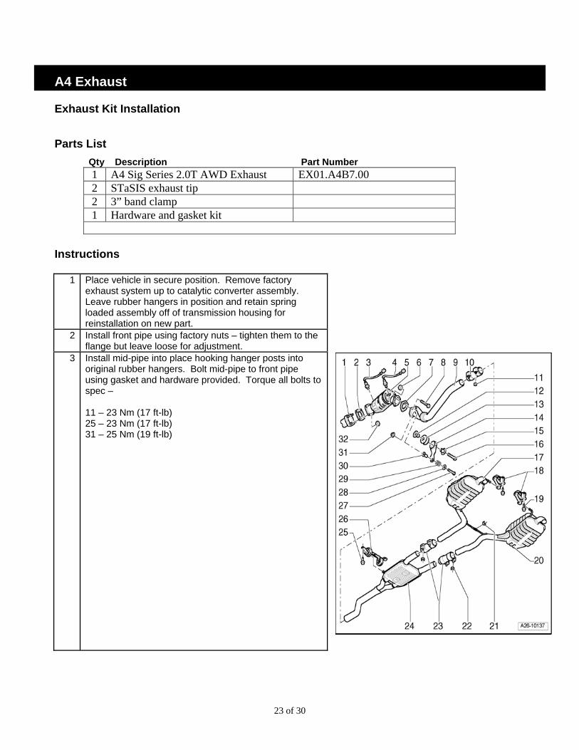
1 Place vehicle in secure position. Remove factory exhaust system up to catalytic converter assembly. Leave rubber hangers in position and retain spring loaded assembly off of transmission housing for reinstallation on new part.
2 Install front pipe using factory nuts – tighten them to the flange but leave loose for adjustment.
3 Install mid-pipe into place hooking hanger posts into original rubber hangers. Bolt mid-pipe to front pipe using gasket and hardware provided. Torque all bolts to spec – 11 – 23 Nm (17 ft-lb) 25 – 23 Nm (17 ft-lb) 31 – 25 Nm (19 ft-lb)
24 of 30
4 Install driver’s side muffler into position with gasket in place using two 7/16” nuts, bolts, and lock washer supplied in hardware kit. Tighten bolts leaving loose enough room for adjustment.
5 Remove hardware from adjustment bracket. Be sure to keep them in order for reinstallation.
6 Install passenger side into position with gasket in place using two 7/16” nuts, bolts, and lock washer supplied in hardware kit. Tighten bolts leaving loose enough for adjustment.
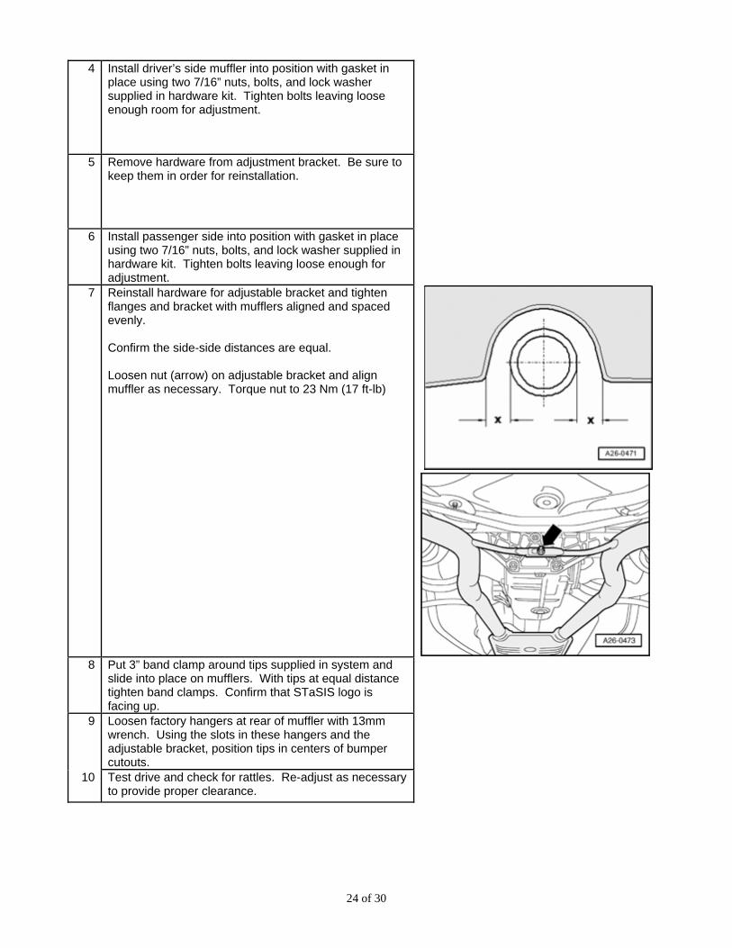
7 Reinstall hardware for adjustable bracket and tighten flanges and bracket with mufflers aligned and spaced evenly. Confirm the side-side distances are equal. Loosen nut (arrow) on adjustable bracket and align muffler as necessary. Torque nut to 23 Nm (17 ft-lb)
8 Put 3” band clamp around tips supplied in system and
slide into place on mufflers. With tips at equal distance tighten band clamps. Confirm that STaSIS logo is facing up.
9 Loosen factory hangers at rear of muffler with 13mm wrench. Using the slots in these hangers and the adjustable bracket, position tips in centers of bumper cutouts.
10 Test drive and check for rattles. Re-adjust as necessary to provide proper clearance.
25 of 30
A4 Center Differential Installation (Challenge Series Only) Parts List: Qty Description Part Number
1 High Bias Torsen DL01.0005.00
Special Tools Required
Qty Description Part Number 1 Drip Tray VAG 1306 1 Torque Wrench VAG 1331
Removal
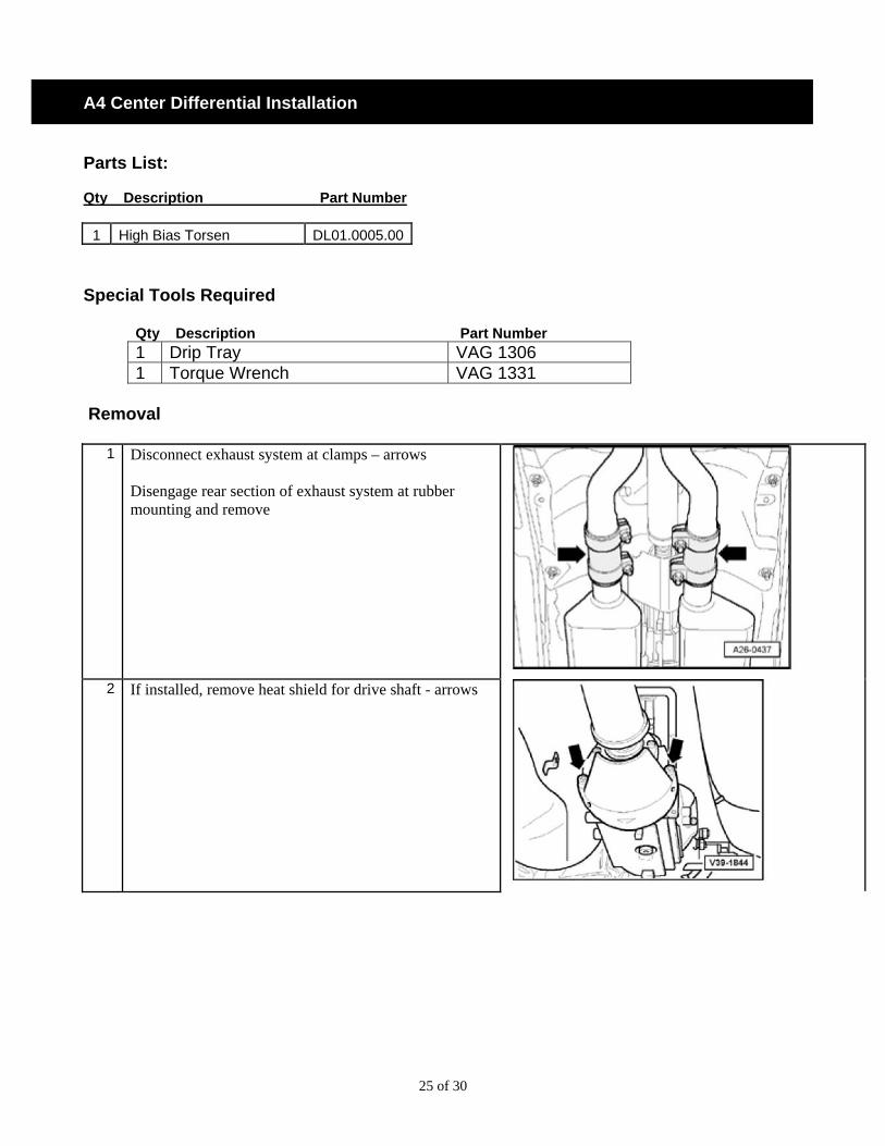
1 Disconnect exhaust system at clamps – arrows Disengage rear section of exhaust system at rubber mounting and remove
2 If installed, remove heat shield for drive shaft - arrows
26 of 30
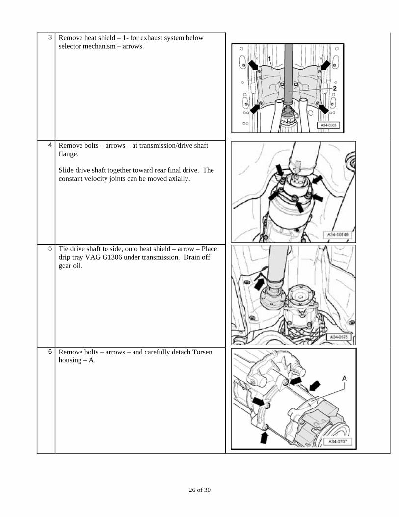
3 Remove heat shield – 1- for exhaust system below selector mechanism – arrows.
4 Remove bolts – arrows – at transmission/drive shaft
flange. Slide drive shaft together toward rear final drive. The constant velocity joints can be moved axially.
5 Tie drive shaft to side, onto heat shield – arrow – Place
drip tray VAG G1306 under transmission. Drain off gear oil.
6 Remove bolts – arrows – and carefully detach Torsen
housing – A.
27 of 30
Installation
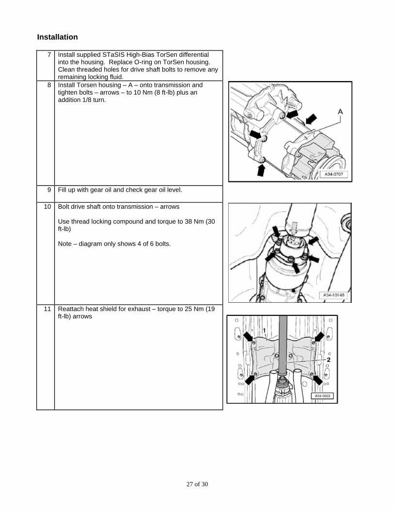
7 Install supplied STaSIS High-Bias TorSen differential into the housing. Replace O-ring on TorSen housing. Clean threaded holes for drive shaft bolts to remove any remaining locking fluid.
8 Install Torsen housing – A – onto transmission and tighten bolts – arrows – to 10 Nm (8 ft-lb) plus an addition 1/8 turn.
9 Fill up with gear oil and check gear oil level.
10 Bolt drive shaft onto transmission – arrows Use thread locking compound and torque to 38 Nm (30 ft-lb) Note – diagram only shows 4 of 6 bolts.
11 Reattach heat shield for exhaust – torque to 25 Nm (19
ft-lb) arrows
28 of 30
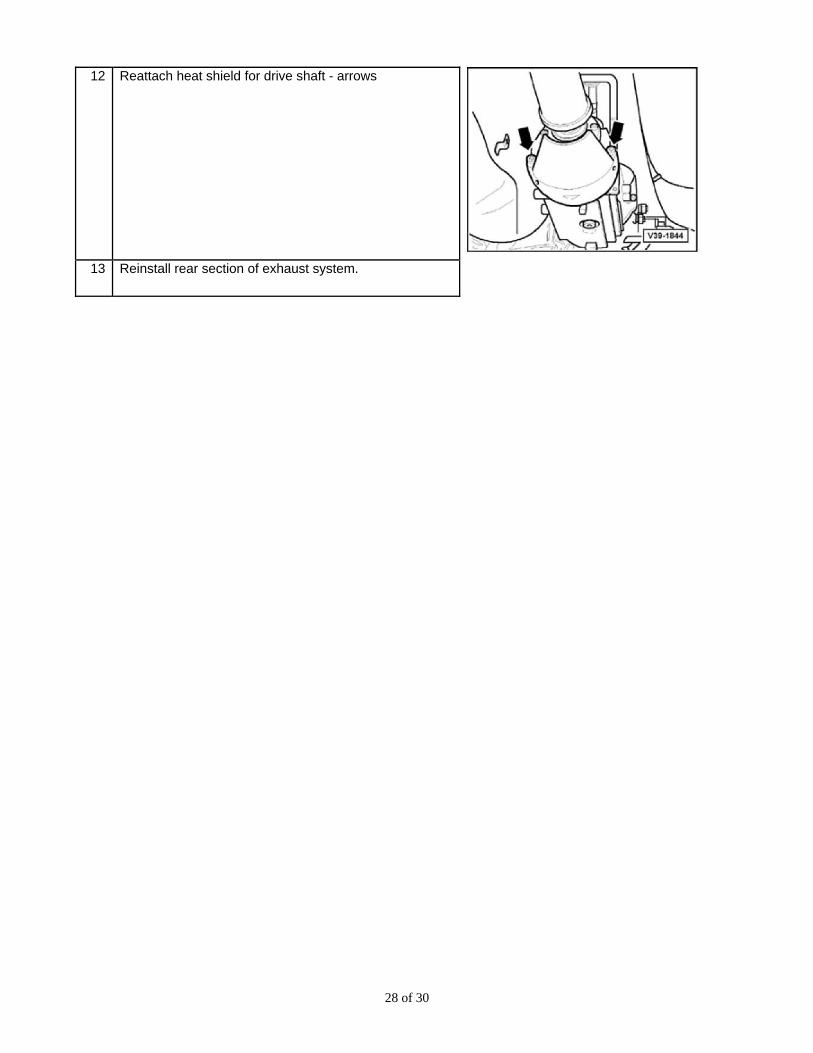
12 Reattach heat shield for drive shaft - arrows
13 Reinstall rear section of exhaust system.
29 of 30
S5 Suspension A4 Signature Series Post Installation Checklist Suspension
o Ensure nylock nuts are completely tightened on the front and rear upper adapter pins. Loose nuts will cause clunking noises from the damper.
o Apply a large amount of grease into the anti-roll bar bushings to prevent possible squeaking.
o Ensure all suspension and anti-roll bar mounting bolts were tightened with the suspension compressed to the curb weight position.
o Check alignment after driving the car for a few miles, as the rubber bushings will cause the car to settle.
Brakes
o Ensure all ABS sensor and Pad wear sensor plugs are reconnected
o Ensure brake line is properly situated. Cycle steering from full lock left to full lock right (with the suspension compressed to the curb weight position) and inspect for possible binding on the brake line.
o After bleeding brakes, cycle pressure to the pedal and double check all bleed screws and brake line connections for possible leakage.
o Drive the car at low speeds for a few miles to check brake operation before beginning brake bedding procedure.
o During bedding do not thermally shock the rotors with aggressive braking before the rotors have come up to temperature. Cracks on new rotors can form due to thermal shock. Gradually increase brake pressures as instructed in the bedding procedure.
o After bedding brakes re-torque wheel nuts to proper torque specifications.
o After installation and bleeding is completed double check brake fluid level.
o If vibration occurs during normal usage, check for abnormal pad wear deposits on the rotor. Double check all fasteners and repeat the bedding process 2-3 cycles until the pad deposits on the rotor becomes uniform.
30 of 30
Exhaust
o During and after install, wipe off all assembly and shipping particles from the exhaust. If dust is not wiped off, once the exhaust gets hot, the particles burn onto the stainless steel finish and become permanent.
o Ensure the exhaust tips on both sides protrude from the bumper evenly and are not touching any body panels.
o Apply anti seize to all assembly bolts to allow for ease of removal.
Differential
o Turning the car at sharp turn angles and low speeds, the tires can slip and chatter due to the differential locking. Inform customer.