Embed Size (px)
Citation preview

I
Hydrogen Control Panel
Installation, Operation and Maintenance


1
GE Power Systems
Hydrogen Control Panel
120V Bottom Entry
Installation, Operation and Maintenance

2
Table of Contents
Section Page
1. General 31.1 Functional Description 31.2 Gas Analyzers 31.3 Major Components 31.4 Environmental Design Conditions and Fabrication 31.5 General Specifications 3
2. Other Equipment 42.2 Flow Indicators 42.3 Metering Valves 42.4 Moisture Filters 42.5 Moisture Indicators 42.6 Differential Pressure Transmitter 42.7 Differential Pressure Indicator 4
3. Mechanical & Electrical Installation 43.1 Mechanical 43.2 Electrical 4
4. Powering Up the System 45. Setting the Scavenging Flow Rates 56. Analyzer Calibration 5
6.10 Nitrogen Purge 66.11 H2/AIR Calibration 66.12 H2/CO2 Calibration 6
7. Setting the Analog Output Signal and Alarms 77.6 Analog Output Setup 77.7 Low and Low-Low Alarms 8
8. Analyzer Confirmation 88.2 Using QT-290A to Confirm QT-290B 88.3 Using QT-290B to Confirm QT-290A 8
9. Standard Operation 810. Maintenance 11
3
IMPORTANT!Always disconnect the power to the panel before servicing the HCP or any of its sub-components. Closeall isolation valves during removal of any component. The valves should be returned to their originalstate once the equipment is replaced. Always perform a leak test after opening any tube line
1. General1.1. Functional Description: The primary function of the hydrogen panel is to analyze and control the
purity of the hydrogen gas within hydrogen cooled generators. To maintain the desired hydrogenpurity of approximately 98% in the generator casing, a small quantity of hydrogen gas iscontinuously scavenged from the seal drain enlargements (turbine end and collector end) anddischarged to atmosphere. Because air entrained in the seal oil is detrained into the seal drainenlargement, its hydrogen gas purity is usually lower than that of the generator casing.Experience has proven that maintaining the purity in the seal oil drain enlargements atapproximately 5 to 10% lower than that of the casing’s results in acceptable purity levels withinthe generator while simultaneously meeting the hydrogen consumption guarantee. Duringstandard operation the hydrogen panel is an automatic piece of equipment controlled by theGenerator Control System. Operating procedures are programmed into the GCS.
1.2. Gas Analyzers: Two hydrogen gas purity analyzers are provided to monitor the purity of the gasbeing scavenged from the generator seal drain enlargements. Panel mounted purity displays areprovided for each gas analyzer. The analyzers output a 4-20 mA signal that corresponds linearlyto a 70-100% hydrogen mixture. This signal is sent to the Generator Control System (GCS) forcontinuous monitoring as well as facilitating low purity and low-low purity alarm set points.
1.3. Major Components:
• Two (2) local displays• Two (2) hydrogen gas analyzers• Two (2) gas analyzer flow meters• One (1) total gas flow meter• One (1) Differential pressure transmitter• One (1) Differential pressure gauge• Three (3) gas filter/dryers• Three (3) moisture indicators• Five (5) Solenoid valves – (2) 2-way & (3) 3-way• Four (4) Metering valves• Isolation valves
1.4. Environmental Design Conditions and Fabrication: The panel is designed for wind loads up to100 mph and seismic zone #4 UBC. All materials or components provided are compatible withhydrogen and carbon dioxide gases where applicable. This applies to both direct and indirectcontact. Any electrical device on the panel that may be exposed to hydrogen gas is rated for use ina Class 1, Division 1, Group B hazardous area.
1.5. General Specifications:• Ambient Temperature: 14° to149° F• Maximum Pressure: 100 psig• Ambient Location: Class I, Division 1, Group B, C & D• Accuracy: ± 0.5 %• Analog Output: 4-20 mA, configurable• Alarm Outputs: 2 configurable contacts• Input Voltage: 100-240 VAC, 50/60 Hz, 40 W max.• Display: 4-line, backlit LCD
4
• Keypad: 6-key, infrared• Measurement Ranges: 70-100% hydrogen in air
0-100% hydrogen in carbon dioxide0-100% air in carbon dioxide
• Weight: Approximately 500 lbs• Dimensions: 80” H x 36” W x 18” D
2. Other Equipment2.1. The two primary components in the HCP are the gas analyzers described above. The manuals
specific to these analyzers are contained later in this manual. The following is a brief description ofthe other components included in the HCP.
2.2. Flow Indicators (FI-2971, FI-2972 & FI-2973): There are two low flow and one total flowindicators on the HCP. The two low flow indicators display the flow through each individualanalyzer. The range for the low flow indicators is 90 to 900 SCCM. The total flow indicatordisplays the total flow through the panel. The range for this indicator is 1200 to 12200 SCCM.
2.3. Metering Valves (HO-2971, HO-2972, HO-2973 & HO-2974): These four metering valves areused to control the low and high end scavenging flow for both the collector end and the turbine end.The setting of these valves is described in Section 4. There is also a metering valve integral to eachanalyzer flow indicator. These two metering valves are used to establish the flow rate through eachanalyzer. This procedure is also discussed in Section 4.
2.4. Moisture Filters: These 3 filters remove the moisture and small particulate from the incominggases. These filters should be checked and replaced on a periodic basis. Replacement cartridgesare available and are described later in the manual.
2.5. Moisture Indicator (MI-2971, MI-2972 & MI-2973): Located at the exit of each filter is a moistureindicator. When the indicator changes color, from blue to pink, it is time to change the associatedmoisture filter and replace the indicator.
2.6. Differential Pressure Transmitter (PDT-292): The differential pressure transmitter on the panelprovides a 4-20 mA signal to the GCS. The range on the transmitter is set to 0-30 inches of water.The transmitter measures the differential pressure across the generator fan. The transmitter is looppowered from the GCS.
2.7. Differential Pressure Indicator (PDI-292): The differential pressure gauge provides a visualindication of the differential pressure across the generator fan. The gauge also has a range of 0-30inches of water.
3. Mechanical & Electrical Installation3.1. Mechanical: The panel must be correctly located, leveled, and supported per GE site
specifications. All customer tubing connections to the turbine must be made in accordance withapplicable GE schematics and specifications, using customer supplied materials. All tubingconnections must be leak checked and leaks corrected before applying power to the HCP.
3.2. Electrical: All electrical connections must be made to the customer power supply, other panels andcontroller per connection diagram provided by GE. Electrical connections to the HCP are madethrough the four conduit connections located in the top of the panel. Refer to CCLLC Dwg. P-26001-701-01 and P-26001-701-02 for the HCP wiring diagrams and terminal layout. Verify thatall seal-offs on the panel have been filled to maintain the area classification rating. Before openingand working inside the electrical junction box on the HCP, verify that an explosive level ofHydrogen is not present. The HCP requires an external power disconnect device such as a switchor circuit breaker. The disconnect device must be marked as such, clearly visible, directlyaccessible, and located within 6 feet of the unit.
4. Powering Up the System4.1. This section should be completed after the HCP is installed, both mechanically and electrically.
5
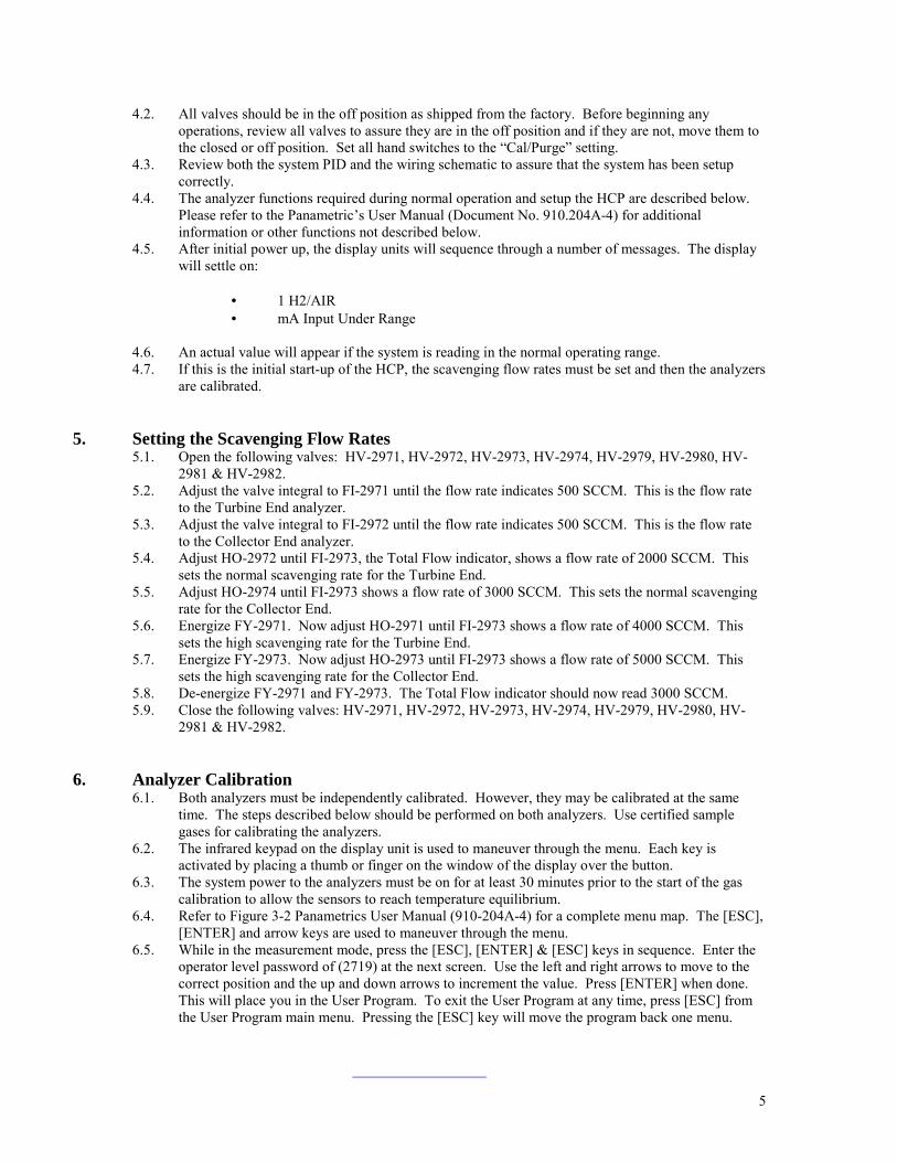
4.2. All valves should be in the off position as shipped from the factory. Before beginning anyoperations, review all valves to assure they are in the off position and if they are not, move them tothe closed or off position. Set all hand switches to the “Cal/Purge” setting.
4.3. Review both the system PID and the wiring schematic to assure that the system has been setupcorrectly.
4.4. The analyzer functions required during normal operation and setup the HCP are described below.Please refer to the Panametric’s User Manual (Document No. 910.204A-4) for additionalinformation or other functions not described below.
4.5. After initial power up, the display units will sequence through a number of messages. The displaywill settle on:
• 1 H2/AIR• mA Input Under Range
4.6. An actual value will appear if the system is reading in the normal operating range.4.7. If this is the initial start-up of the HCP, the scavenging flow rates must be set and then the analyzers
are calibrated.
5. Setting the Scavenging Flow Rates5.1. Open the following valves: HV-2971, HV-2972, HV-2973, HV-2974, HV-2979, HV-2980, HV-
2981 & HV-2982.5.2. Adjust the valve integral to FI-2971 until the flow rate indicates 500 SCCM. This is the flow rate
to the Turbine End analyzer.5.3. Adjust the valve integral to FI-2972 until the flow rate indicates 500 SCCM. This is the flow rate
to the Collector End analyzer.5.4. Adjust HO-2972 until FI-2973, the Total Flow indicator, shows a flow rate of 2000 SCCM. This
sets the normal scavenging rate for the Turbine End.5.5. Adjust HO-2974 until FI-2973 shows a flow rate of 3000 SCCM. This sets the normal scavenging
rate for the Collector End.5.6. Energize FY-2971. Now adjust HO-2971 until FI-2973 shows a flow rate of 4000 SCCM. This
sets the high scavenging rate for the Turbine End.5.7. Energize FY-2973. Now adjust HO-2973 until FI-2973 shows a flow rate of 5000 SCCM. This
sets the high scavenging rate for the Collector End.5.8. De-energize FY-2971 and FY-2973. The Total Flow indicator should now read 3000 SCCM.5.9. Close the following valves: HV-2971, HV-2972, HV-2973, HV-2974, HV-2979, HV-2980, HV-
2981 & HV-2982.
6. Analyzer Calibration6.1. Both analyzers must be independently calibrated. However, they may be calibrated at the same
time. The steps described below should be performed on both analyzers. Use certified samplegases for calibrating the analyzers.
6.2. The infrared keypad on the display unit is used to maneuver through the menu. Each key isactivated by placing a thumb or finger on the window of the display over the button.
6.3. The system power to the analyzers must be on for at least 30 minutes prior to the start of the gascalibration to allow the sensors to reach temperature equilibrium.
6.4. Refer to Figure 3-2 Panametrics User Manual (910-204A-4) for a complete menu map. The [ESC],[ENTER] and arrow keys are used to maneuver through the menu.
6.5. While in the measurement mode, press the [ESC], [ENTER] & [ESC] keys in sequence. Enter theoperator level password of (2719) at the next screen. Use the left and right arrows to move to thecorrect position and the up and down arrows to increment the value. Press [ENTER] when done.This will place you in the User Program. To exit the User Program at any time, press [ESC] fromthe User Program main menu. Pressing the [ESC] key will move the program back one menu.

6
6.6. Once in the User Program select the “CAL” option by highlighting the choice with the arrow keysand pressing the [ENTER] key twice. Select “CAL” again. Next select the “MANUAL CAL”option.
6.7. The system will offer both the “H2/AIR” and “H2/CO2” curves for calibration.6.8. Verify that HV-2983, HV-2984, HV-2985 & HV-2986 are in the closed position. Move hand
switches, 30H2STAT1, 30H2STAT2 & 30H2STAT3 to the “Cal/Purge” setting. This will energizesolenoids FY-2972, FY-2974 & FY-2981 allowing flow from the various sample gas ports.
6.9. Open HV-2979, HV-2980, HV-2981 & HV-2982.6.10. Nitrogen Purge: Open HV-2985. This will allow Nitrogen to flow through the system. Allow the
gas to flow for 3-4 minutes to completely purge the system. Shutoff HV-2985.6.11. H2/AIR Calibration:
6.11.1. Select the “H2/AIR” Gas Curve.6.11.2. Next select “Zero.”6.11.3. At the following prompt enter the percentage of H2 in the sample gas (usually 0.00%
for the zero gas). Use the arrow keys to arrive at the correct number and press[ENTER].
6.11.4. The next screen will display “Hold 4-20 mA Output During Calibration?” Select“YES.”
6.11.5. The next screen will display “Introduce Cal Gas.” Open HV-2985 to allow Nitrogenflow. Once the calibration gas is introduced, select “Next.”
6.11.6. The screen will display the percentage of H2 and will display “Hit Next When Stable.”Allow a minimum of 30 minutes for the display reading to stabilize. Once the displayreading stabilizes, select “Next.”
6.11.7. The meter will next display the Zero Drift value and whether the unit “Passed” or“Failed” the calibration. When the display shows “Passed,” select “Finished.”
6.11.8. Shutoff HV-2985 to stop the Nitrogen flow.6.11.9. If the calibration “Failed,” perform steps 6.11.1 through 6.11.7. If the unit fails again,
contact the factory (Control Center, LLC, 407-681-5000).6.11.10. Next select “Span.”6.11.11. At the following prompt enter the percentage of H2 in the sample gas. Use the arrow
keys to arrive at the correct number and press [ENTER].6.11.12. The next screen will ask if you would like to hold the current 4-20 mA output during
calibration. Select “YES.”6.11.13. The next screen will state “Introduce Cal Gas.” Open HV-2984 to allow H2 flow.
Once the calibration gas is introduced, select “Next.”6.11.14. The screen will display the percentage of H2 and will display “Hit Next When Stable.”
Allow a minimum of 30 minutes for the display reading to stabilize. Once the displayreading stabilizes, select “Next.”
6.11.15. The meter will next display the Zero Drift value and whether the unit “Passed” or“Failed” the calibration. When the display shows “Passed,” select “Finished.”
6.11.16. Shutoff HV-2984 to stop the Hydrogen flow.6.11.17. If the calibration “Failed,” perform steps 6.11.10 through 6.11.16. If the unit fails
again, contact the factory.6.11.18. Once the span calibration is complete, press [ESC] once to return to the “Gas Curve”
selection screen.6.12. H2/CO2 Calibration:
6.12.1. Select the “H2/CO2” Gas Curve.6.12.2. Next select “Zero.”6.12.3. At the following prompt enter the percentage of H2 in the sample gas (usually 0.00%
for the zero gas). Use the arrow keys to arrive at the correct number and press[ENTER].
6.12.4. The next screen will ask if you would like to hold the current 4-20 mA output duringcalibration. Select “YES.”
6.12.5. The next screen will state “Introduce Cal Gas.” Open HV-2986 to allow CO2Calibration Gas flow. Once the calibration gas is introduced, select “Next.”
7
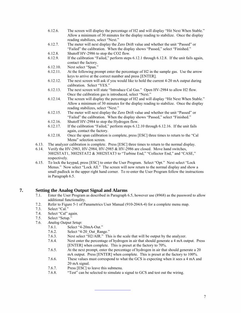
6.12.6. The screen will display the percentage of H2 and will display “Hit Next When Stable.”Allow a minimum of 30 minutes for the display reading to stabilize. Once the displayreading stabilizes, select “Next.”
6.12.7. The meter will next display the Zero Drift value and whether the unit “Passed” or“Failed” the calibration. When the display shows “Passed,” select “Finished.”
6.12.8. Shutoff HV-2986 to stop the CO2 flow.6.12.9. If the calibration “Failed,” perform steps 6.12.1 through 6.12.8. If the unit fails again,
contact the factory.6.12.10. Next select “Span.”6.12.11. At the following prompt enter the percentage of H2 in the sample gas. Use the arrow
keys to arrive at the correct number and press [ENTER].6.12.12. The next screen will ask if you would like to hold the current 4-20 mA output during
calibration. Select “YES.”6.12.13. The next screen will state “Introduce Cal Gas.” Open HV-2984 to allow H2 flow.
Once the calibration gas is introduced, select “Next.”6.12.14. The screen will display the percentage of H2 and will display “Hit Next When Stable.”
Allow a minimum of 30 minutes for the display reading to stabilize. Once the displayreading stabilizes, select “Next.”
6.12.15. The meter will next display the Zero Drift value and whether the unit “Passed” or“Failed” the calibration. When the display shows “Passed,” select “Finished.”
6.12.16. Shutoff HV-2984 to stop the Hydrogen flow.6.12.17. If the calibration “Failed,” perform steps 6.12.10 through 6.12.16. If the unit fails
again, contact the factory.6.12.18. Once the span calibration is complete, press [ESC] three times to return to the “Cal
Menu” selection screen.6.13. The analyzer calibration is complete. Press [ESC] three times to return to the normal display.6.14. Verify the HV-2983, HV-2984, HV-2985 & HV-2986 are closed. Move hand switches,
30H2STAT1, 30H2STAT2 & 30H2STAT3 to “Turbine End,” “Collector End,” and “CASE,”respectively.
6.15. To lock the keypad, press [ESC] to enter the User Program. Select “Opt.” Next select “LockMenus.” Now select “Lock All.” The screen will now return to the normal display and show asmall padlock in the upper right hand corner. To re-enter the User Program follow the instructionsin Paragraph 6.5.
7. Setting the Analog Output Signal and Alarms7.1. Enter the User Program as described in Paragraph 6.5, however use (8968) as the password to allow
additional functionality.7.2. Refer to Figure 5-1 of Panametrics User Manual (910-204A-4) for a complete menu map.7.3. Select “Cal.”7.4. Select “Cal” again.7.5. Select “Setup.”7.6. Analog Output Setup:
7.6.1. Select “4-20mA-Out.”7.6.2. Select “4-20_Out_Range.”7.6.3. Next select “H2/AIR.” This is the scale that will be output by the analyzer.7.6.4. Next enter the percentage of hydrogen in air that should generate a 4 mA output. Press
[ENTER] when complete. This is preset at the factory to 70%.7.6.5. At the next prompt, enter the percentage of hydrogen in air that should generate a 20
mA output. Press [ENTER] when complete. This is preset at the factory to 100%.7.6.6. These values must correspond to what the GCS is expecting when it sees a 4 mA and
20 mA signal.7.6.7. Press [ESC] to leave this submenu.7.6.8. “Test” can be selected to simulate a signal to GCS and test out the wiring.
8
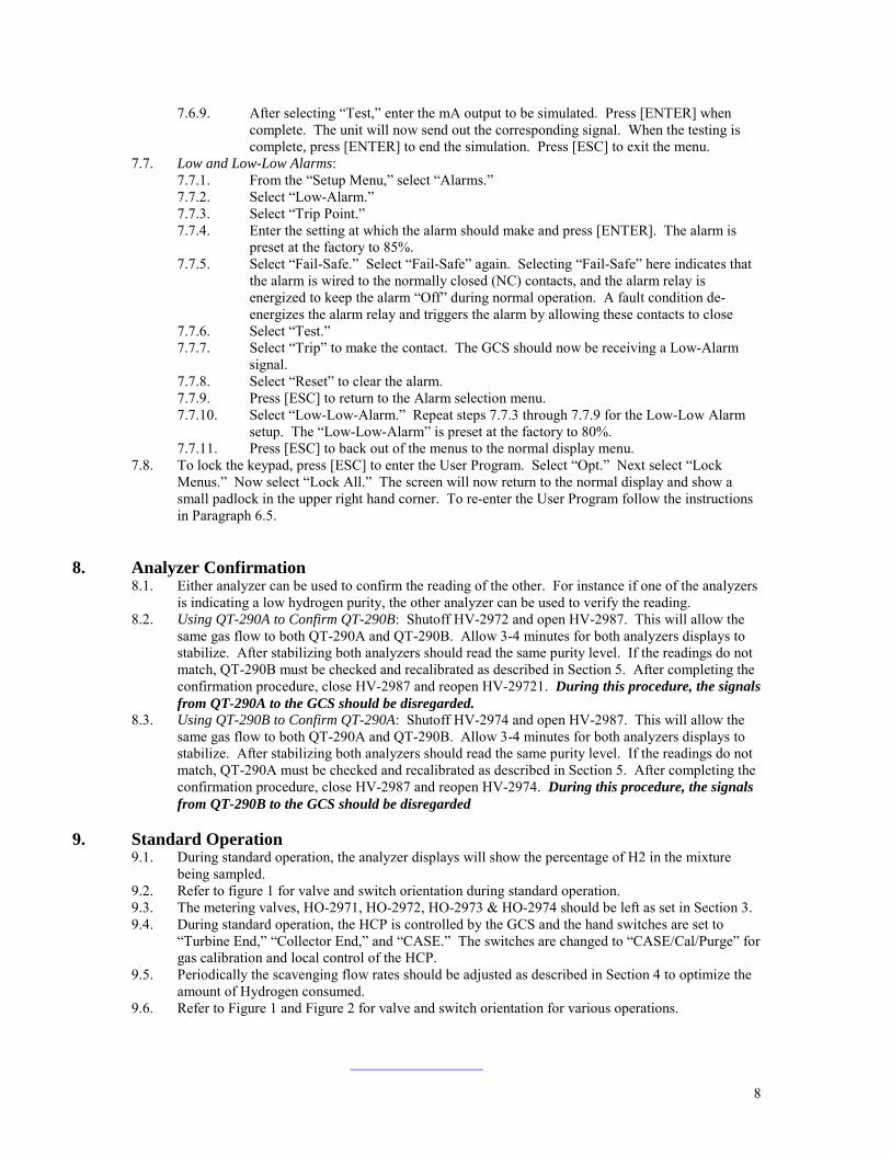
7.6.9. After selecting “Test,” enter the mA output to be simulated. Press [ENTER] whencomplete. The unit will now send out the corresponding signal. When the testing iscomplete, press [ENTER] to end the simulation. Press [ESC] to exit the menu.
7.7. Low and Low-Low Alarms:7.7.1. From the “Setup Menu,” select “Alarms.”7.7.2. Select “Low-Alarm.”7.7.3. Select “Trip Point.”7.7.4. Enter the setting at which the alarm should make and press [ENTER]. The alarm is
preset at the factory to 85%.7.7.5. Select “Fail-Safe.” Select “Fail-Safe” again. Selecting “Fail-Safe” here indicates that
the alarm is wired to the normally closed (NC) contacts, and the alarm relay isenergized to keep the alarm “Off” during normal operation. A fault condition de-energizes the alarm relay and triggers the alarm by allowing these contacts to close
7.7.6. Select “Test.”7.7.7. Select “Trip” to make the contact. The GCS should now be receiving a Low-Alarm
signal.7.7.8. Select “Reset” to clear the alarm.7.7.9. Press [ESC] to return to the Alarm selection menu.7.7.10. Select “Low-Low-Alarm.” Repeat steps 7.7.3 through 7.7.9 for the Low-Low Alarm
setup. The “Low-Low-Alarm” is preset at the factory to 80%.7.7.11. Press [ESC] to back out of the menus to the normal display menu.
7.8. To lock the keypad, press [ESC] to enter the User Program. Select “Opt.” Next select “LockMenus.” Now select “Lock All.” The screen will now return to the normal display and show asmall padlock in the upper right hand corner. To re-enter the User Program follow the instructionsin Paragraph 6.5.
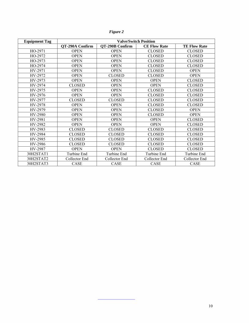
8. Analyzer Confirmation8.1. Either analyzer can be used to confirm the reading of the other. For instance if one of the analyzers
is indicating a low hydrogen purity, the other analyzer can be used to verify the reading.8.2. Using QT-290A to Confirm QT-290B: Shutoff HV-2972 and open HV-2987. This will allow the
same gas flow to both QT-290A and QT-290B. Allow 3-4 minutes for both analyzers displays tostabilize. After stabilizing both analyzers should read the same purity level. If the readings do notmatch, QT-290B must be checked and recalibrated as described in Section 5. After completing theconfirmation procedure, close HV-2987 and reopen HV-29721. During this procedure, the signalsfrom QT-290A to the GCS should be disregarded.
8.3. Using QT-290B to Confirm QT-290A: Shutoff HV-2974 and open HV-2987. This will allow thesame gas flow to both QT-290A and QT-290B. Allow 3-4 minutes for both analyzers displays tostabilize. After stabilizing both analyzers should read the same purity level. If the readings do notmatch, QT-290A must be checked and recalibrated as described in Section 5. After completing theconfirmation procedure, close HV-2987 and reopen HV-2974. During this procedure, the signalsfrom QT-290B to the GCS should be disregarded
9. Standard Operation9.1. During standard operation, the analyzer displays will show the percentage of H2 in the mixture
being sampled.9.2. Refer to figure 1 for valve and switch orientation during standard operation.9.3. The metering valves, HO-2971, HO-2972, HO-2973 & HO-2974 should be left as set in Section 3.9.4. During standard operation, the HCP is controlled by the GCS and the hand switches are set to
“Turbine End,” “Collector End,” and “CASE.” The switches are changed to “CASE/Cal/Purge” forgas calibration and local control of the HCP.
9.5. Periodically the scavenging flow rates should be adjusted as described in Section 4 to optimize theamount of Hydrogen consumed.
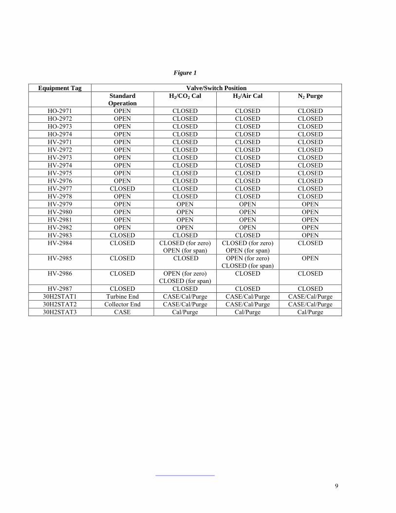
9.6. Refer to Figure 1 and Figure 2 for valve and switch orientation for various operations.
9
Figure 1
Equipment Tag Valve/Switch PositionStandardOperation
H2/CO2 Cal H2/Air Cal N2 Purge
HO-2971 OPEN CLOSED CLOSED CLOSEDHO-2972 OPEN CLOSED CLOSED CLOSEDHO-2973 OPEN CLOSED CLOSED CLOSEDHO-2974 OPEN CLOSED CLOSED CLOSEDHV-2971 OPEN CLOSED CLOSED CLOSEDHV-2972 OPEN CLOSED CLOSED CLOSEDHV-2973 OPEN CLOSED CLOSED CLOSEDHV-2974 OPEN CLOSED CLOSED CLOSEDHV-2975 OPEN CLOSED CLOSED CLOSEDHV-2976 OPEN CLOSED CLOSED CLOSEDHV-2977 CLOSED CLOSED CLOSED CLOSEDHV-2978 OPEN CLOSED CLOSED CLOSEDHV-2979 OPEN OPEN OPEN OPENHV-2980 OPEN OPEN OPEN OPENHV-2981 OPEN OPEN OPEN OPENHV-2982 OPEN OPEN OPEN OPENHV-2983 CLOSED CLOSED CLOSED OPENHV-2984 CLOSED CLOSED (for zero)
OPEN (for span)CLOSED (for zero)
OPEN (for span)CLOSED
HV-2985 CLOSED CLOSED OPEN (for zero)CLOSED (for span)
OPEN
HV-2986 CLOSED OPEN (for zero)CLOSED (for span)
CLOSED CLOSED
HV-2987 CLOSED CLOSED CLOSED CLOSED30H2STAT1 Turbine End CASE/Cal/Purge CASE/Cal/Purge CASE/Cal/Purge30H2STAT2 Collector End CASE/Cal/Purge CASE/Cal/Purge CASE/Cal/Purge30H2STAT3 CASE Cal/Purge Cal/Purge Cal/Purge
10
Figure 2
Equipment Tag Valve/Switch PositionQT-290A Confirm QT-290B Confirm CE Flow Rate TE Flow Rate
HO-2971 OPEN OPEN CLOSED CLOSEDHO-2972 OPEN OPEN CLOSED CLOSEDHO-2973 OPEN OPEN CLOSED CLOSEDHO-2974 OPEN OPEN CLOSED CLOSEDHV-2971 OPEN OPEN CLOSED OPENHV-2972 OPEN CLOSED CLOSED OPENHV-2973 OPEN OPEN OPEN CLOSEDHV-2974 CLOSED OPEN OPEN CLOSEDHV-2975 OPEN OPEN CLOSED CLOSEDHV-2976 OPEN OPEN CLOSED CLOSEDHV-2977 CLOSED CLOSED CLOSED CLOSEDHV-2978 OPEN OPEN CLOSED CLOSEDHV-2979 OPEN OPEN CLOSED OPENHV-2980 OPEN OPEN CLOSED OPENHV-2981 OPEN OPEN OPEN CLOSEDHV-2982 OPEN OPEN OPEN CLOSEDHV-2983 CLOSED CLOSED CLOSED CLOSEDHV-2984 CLOSED CLOSED CLOSED CLOSEDHV-2985 CLOSED CLOSED CLOSED CLOSEDHV-2986 CLOSED CLOSED CLOSED CLOSEDHV-2987 OPEN OPEN CLOSED CLOSED
30H2STAT1 Turbine End Turbine End Turbine End Turbine End30H2STAT2 Collector End Collector End Collector End Collector End30H2STAT3 CASE CASE CASE CASE
11
10. Maintenance10.1. General: Basic maintenance of the HCP consists of cleaning, calibration checks, and filter
replacement. Non-repairable items such as gauges, switches, etc. are normally removed andreplaced, or can be re-calibrated if applicable. Refer to instructions from the componentmanufacturers found later in this manual. Repairable items such as valves may fall under some orall of the following procedures: removal, disassembly, cleaning, inspection, repair or replacementof components, tolerance limits, re-assembly, and alignment. Manufacturer’s instructions shouldbe referred to and can be found in the body of this manual.
10.2. Daily maintenance should consist of checking and adjusting the analyzer and scavenging flow rates.General panel cleaning should be performed regularly. Also hydrogen purity should be checkeddaily.
10.3. Weekly inspections should consist of the following:• Inspect the moisture indicators. Replace the gas purifier cartridge if indicator shows excessive
moisture.• Any build up of liquid should be released from the purifier cylinders. Make sure that there is
no pressure on the system. Open drain valve to release liquid. CAUTION: THE PURIFIERSMAY CONTAIN HYDROGEN GAS; USE PROPER SAFETY PRECAUTIONS.
10.4 Every six months check analyzer and calibration voltages
IMPORTANT! Always disconnect the power to the panel before servicing the HCP or any ofits sub-components. Close all isolation valves during removal of any component. The valvesshould be returned to their original state once the equipment is replaced. Always perform aleak test after opening any tube line.