Embed Size (px)
Citation preview

OW
NER
S H
AN
DBO
OK
M
AN
UA
LE D
’USO
MA
NU
EL D
’UTI
LISA
TIO
NM
AN
UA
L D
E IN
STR
UC
CIO
NES
2001
40
0/5
20
SX,
MX
C,
EXC
R
AC
ING
BED
IEN
UN
GSA
NLE
ITU
NG
Art
.Nr.
3.20
5.98
06
/200
00

EN
GLIS
H
1
IMPORTANT
WE STRONGLY SUGGEST THAT YOU READ THIS MANUAL
CAREFULLY AND COMPLETELY BEFORE GOING ON YOUR FIRST
RIDE. IT CONTAINS A GREAT DEAL OF INFORMATION AND
ADVICE WHICH WILL HELP YOU USE AND HANDLE YOUR BIKE
PROPERLY. IN YOUR OWN INTEREST, PLEASE PAY PARTICULAR
ATTENTION TO NOTICES THAT ARE MARKED AS FOLLOWS:
� WARNING �IGNORING THESE INSTRUCTIONS, CAN ENDANGER YOURBODY AND YOUR LIFE.
! CAUTION !IGNORING THESE INSTRUCTIONS COULD CAUSE DAMAGE TOPARTS OF YOUR MOTORCYCLE OR THAT THE MOTOR-CYCLEIS NOT ROAD-SAFE ANYMORE.
Please insert the series numbers of your motorcycle in the boxes below
Chassis number
Engine number
Stamp of dealer
Tampering with noise control system prohibitedOwners are warned that the law may prohibit:(a) The removal or rendering inoperative by any person other than for purposes of mainten-
ance, repair or replacement, of any device or element of design incorporated into any newvehicle for the purpose of noise control prior to its sale or delivery to the ultimate purchaseror while it is in use; and
(b) the use of the vehicle after such device or element of design has been removed or renderedinoperative by any person.
COMSUMER INFORMATION FOR AUSTRALIA ONLY
KTM SPORTMOTORCYCLE AG RESERVES THE RIGHT TO MODIFY ANY EQUIPMENT, TECHNICAL SPECIFICATIONS, COLORS,MATERIALS, SERVICES OFFERED AND RENDERED, AND THE LIKE SO AS TO ADAPT THEM TO LOCAL CONDITIONS WITHOUT
PREVIOUS ANNOUNCEMENT AND WITHOUT GIVING REASONS, OR TO CANCEL ANY OF THE ABOVE ITEMS WITHOUT SUBSTI-TUTING THEM WITH OTHERS. IT SHALL BE ACCEPTABLE TO STOP MANUFACTURING A CERTAIN MODEL WITHOUT PREVIOUS
ANNOUNCEMENT. IN THE EVENT OF SUCH MODIFICATIONS, PLEASE ASK YOUR LOCAL KTM DEALER FOR INFORMATION.WE SHALL NOT BE HELD LIABLE FOR ANY PRINTING ERRORS.

EN
GLIS
H
2
Introduction
We would like to congratulate you on your purchase of a KTM motorcycle. Let us also take thisopportunity to thank you for putting your trust in us; we will not let you down.
You are now owner of a sporty and modern motorcycle which you are bound to have a great timewith provided you care for it properly. Before going for a first ride on your motorbike, you shouldread this Owner’s Handbook carefully, even if this takes some of your precious time, so as tofamiliarize yourself with how your motorbike is to be operated and which features it offers you.Only by doing so will you learn how you can best tune your motorcycle to your needs and howyou can avoid bodily injuries. In addition, this Owner’s Handbook contains invaluable informa-tion about motorcycle maintenance. At the time of printing, this User's Guide corresponded to thelatest state of this model family. It is, however, possible that we may have made slight modificati-ons in the meantime due to development in our motorcycle design.The Owner’s Handbook is an essential part of the motorbike and should - when the bike is sold -be handed over to the new owner.
Many motorcyclists have a good working knowledge of motorcycle mechanics; if this is true inyour case, you will be able to use this Owner’s Handbook to carry out most of the maintenancesteps yourself. If, on the other hand, you are not very familiar with motorcycles, it might be betterto have a professional KTM dealer perform those steps marked by * found in the chapter entitled“Maintenance Work on Chassis and Engine” of this manual.
Take special care to follow the recommended run in, inspection, and maintenance intervals. Heeding these guidelines will significantly increase the life of your motorcycle. Be sure tohave any maintenance jobs performed by an authorized KTM dealer.Address your special requests to an authorized KTM dealer who, should the need arise, will besupported by the KTM importer.
Please do not forget to don your helmet, eye protection, and protective clothing when going for aride. KTM riders are responsible riders! We wish you a lot of fun when driving !
KTM SPORTMOTORCYCLE AG5230 MATTIGHOFEN, AUSTRIA
Attachments: 1 spare parts manual chassis1 spare parts manual engine
ALL RIGHTS RESERVED TO MAKE ALTERNATIONS TO DESIGN AND MODEL.
© by KTM SPORTMOTORCYCLE AG, AUSTRIA All rights reserved
KTM Austria’s certificate of achievement for its QualitySystem ISO 9001 is the beginning of an on-going totalre-engineering quality plan for a brighter tomorrow.
EN
GLIS
H
3
Page
SERIAL NUMBER LOCATIONS . . . . . . . . . . . . . . . . . . . . . .4
Chassis number . . . . . . . . . . . . . . . . . . . . . . . . . . . . . . . .4
Engine number, engine type . . . . . . . . . . . . . . . . . . . . . .4
OPERATION INSTRUMENTS . . . . . . . . . . . . . . . . . . . . . . .4
Clutch lever . . . . . . . . . . . . . . . . . . . . . . . . . . . . . . . . . .4
Hand decompression lever . . . . . . . . . . . . . . . . . . . . . . .4
Hand brake lever . . . . . . . . . . . . . . . . . . . . . . . . . . . . . . .4
Digital speedometer, indicator lamps (EXC) . . . . . . . . . . .5
Digital speedometer (EXC) . . . . . . . . . . . . . . . . . . . . . . .5
Odometer (EXC USA) . . . . . . . . . . . . . . . . . . . . . . . . . . .5
Speedometer, indicator lamps (EXC - Australia) . . . . . . . .5
Short circuit button (SX/MXC) . . . . . . . . . . . . . . . . . . . .5
Combination switch (EXC) . . . . . . . . . . . . . . . . . . . . . . . .6
Headlamp switch (EXC USA) . . . . . . . . . . . . . . . . . . . . . .6
Flasher switch . . . . . . . . . . . . . . . . . . . . . . . . . . . . . . . . .6
Emergency OFF button (EXC) . . . . . . . . . . . . . . . . . . . . .6
Emergency OFF switch (EXC Australia) . . . . . . . . . . . . . .6
Filler cap . . . . . . . . . . . . . . . . . . . . . . . . . . . . . . . . . . . . .7
Fuel . . . . . . . . . . . . . . . . . . . . . . . . . . . . . . . . . . . . . . . . .7
Fuel tap . . . . . . . . . . . . . . . . . . . . . . . . . . . . . . . . . . . . . .7
Choke . . . . . . . . . . . . . . . . . . . . . . . . . . . . . . . . . . . . . . .8
Shift lever . . . . . . . . . . . . . . . . . . . . . . . . . . . . . . . . . . . .8
Kickstarter . . . . . . . . . . . . . . . . . . . . . . . . . . . . . . . . . . . .8
Foot brake pedal . . . . . . . . . . . . . . . . . . . . . . . . . . . . . . .8
Compression damping of fork . . . . . . . . . . . . . . . . . . . . .8
Rebound damping of fork . . . . . . . . . . . . . . . . . . . . . . . .9
Compression damping of shock absorber . . . . . . . . . . . .9
Rebound damping of shock absorber . . . . . . . . . . . . . . .9
Steering lock . . . . . . . . . . . . . . . . . . . . . . . . . . . . . . . . . .9
Side stand . . . . . . . . . . . . . . . . . . . . . . . . . . . . . . . . . . . .9
DRIVING INSTRUCTIONS . . . . . . . . . . . . . . . . . . . . . . . . .10
PERIODIC LUBRICATION- AND MAINTENANCE-SCHEDULE . .14
MAINTENANCE WORK ON CHASSIS AND ENGINE . . . . .16
Changing the original position of the clutch lever . . . . .16
Checking and adjusting the steering head bearing . . . . .16
Breather plug front fork . . . . . . . . . . . . . . . . . . . . . . . . .17
Cleaning the dust sleeves of the telescopic fork . . . . . . .17
How to change the handlebar position . . . . . . . . . . . . .17
Changing the spring preload of shock absorber . . . . . . .18
Pivot bearing . . . . . . . . . . . . . . . . . . . . . . . . . . . . . . . . .18
Check chain tension . . . . . . . . . . . . . . . . . . . . . . . . . . .18
Correct chain tension . . . . . . . . . . . . . . . . . . . . . . . . . .19
Chain maintenance . . . . . . . . . . . . . . . . . . . . . . . . . . . .19
Chain wear . . . . . . . . . . . . . . . . . . . . . . . . . . . . . . . . . .19
General informations about KTM disc brakes . . . . . . . .20
Adjusting of free travel at the hand brake lever . . . . . . .20
Checking of brake fluid level - front brake . . . . . . . . . . .21
Refilling the front brake fluid reservoir . . . . . . . . . . . . . .21
PageChecking the front brake pads . . . . . . . . . . . . . . . . . . .21Replacing the front brake pads . . . . . . . . . . . . . . . . . . .21Changing the basic position of the brake pedal . . . . . .22Checking rear brake fluid level . . . . . . . . . . . . . . . . . . .22Refilling the rear brake fluid reservoir . . . . . . . . . . . . . .22Checking the rear brake pads . . . . . . . . . . . . . . . . . . . .23Replacing the rear brake pads . . . . . . . . . . . . . . . . . . .23Dismounting and mounting the front wheel . . . . . . . . .23Dismounting and mounting the rear wheel . . . . . . . . .24Tires, air pressure . . . . . . . . . . . . . . . . . . . . . . . . . . . . .25Checking spoke tension . . . . . . . . . . . . . . . . . . . . . . . .25Replacing the battery of the digital speedometer . . . . .25Adjusting digital speedometer . . . . . . . . . . . . . . . . . . .26Check/set distance of magnetic sensor . . . . . . . . . . . . .27Battery (MXC/EXC) . . . . . . . . . . . . . . . . . . . . . . . . . . .28Charging battery . . . . . . . . . . . . . . . . . . . . . . . . . . . . .28Fuse (MXC/EXC) . . . . . . . . . . . . . . . . . . . . . . . . . . . . .29Replacing head light/parking light lamp (H4) . . . . . . . .29Cooling system . . . . . . . . . . . . . . . . . . . . . . . . . . . . . .30Checking the coolant level . . . . . . . . . . . . . . . . . . . . . .30Bleeding the cooling system . . . . . . . . . . . . . . . . . . . . .30Cleaning the air filter . . . . . . . . . . . . . . . . . . . . . . . . . .31Replacing the glass fiber yarn packing of the silencer . .31Cleaning the spark arrestor (MXC/EXC USA) . . . . . . . .31Draining of float chamber of the carburetor . . . . . . . . .32Checking adjustment of the hand decompression release cable .32Adjust the throttle cables . . . . . . . . . . . . . . . . . . . . . . .32Checking the oil level of the hydraulic clutch . . . . . . . .32Bleeding of the hydraulic clutch . . . . . . . . . . . . . . . . . .32Carburetor adjust idling . . . . . . . . . . . . . . . . . . . . . . . .33Adjusting the mixture control screw . . . . . . . . . . . . . . .33Checking the float level . . . . . . . . . . . . . . . . . . . . . . . .33Draining of float chamber of the carburetor . . . . . . . . .34Oil circuit . . . . . . . . . . . . . . . . . . . . . . . . . . . . . . . . . . .34Checking engin oil level . . . . . . . . . . . . . . . . . . . . . . . .34Engine oil . . . . . . . . . . . . . . . . . . . . . . . . . . . . . . . . . . .35Changing the engine oil . . . . . . . . . . . . . . . . . . . . . . . .35
TROUBLE SHOOTING . . . . . . . . . . . . . . . . . . . . . . . . . . .37
CLEANING . . . . . . . . . . . . . . . . . . . . . . . . . . . . . . . . . . . .39
CONSERVATION FOR WINTER OPERARION . . . . . . . . .39
STORAGE . . . . . . . . . . . . . . . . . . . . . . . . . . . . . . . . . . . . .39
Re-initiation after time of storage . . . . . . . . . . . . . . . . .39
TECHNICAL SPECIFICATIONS - ENGINE . . . . . . . . . . . . .40
TECHNICAL SPECIFICATIONS - CHASSIS . . . . . . . . . . . . .42
HEAD WORD INDEX . . . . . . . . . . . . . . . . . . . . . . . . . . . .43
WIRING DIAGRAMME . . . . . . . . . . . . . . . . . . . . . .Appendix
INDEX
EN
GLIS
H
4
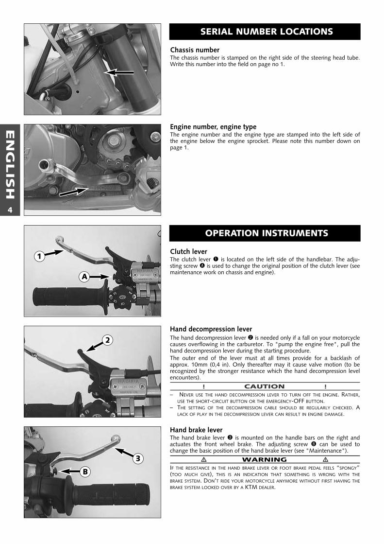
Chassis numberThe chassis number is stamped on the right side of the steering head tube.Write this number into the field on page no 1.
Engine number, engine typeThe engine number and the engine type are stamped into the left side ofthe engine below the engine sprocket. Please note this number down onpage 1.
SERIAL NUMBER LOCATIONS
OPERATION INSTRUMENTS
Clutch lever The clutch lever 1 is located on the left side of the handlebar. The adju-sting screw A is used to change the original position of the clutch lever (seemaintenance work on chassis and engine).
Hand decompression leverThe hand decompression lever 2 is needed only if a fall on your motorcyclecauses overflowing in the carburetor. To "pump the engine free", pull thehand decompression lever during the starting procedure.The outer end of the lever must at all times provide for a backlash ofapprox. 10mm (0,4 in). Only thereafter may it cause valve motion (to be recognized by the stronger resistance which the hand decompression levelencounters).
! CAUTION !– NEVER USE THE HAND DECOMPRESSION LEVER TO TURN OFF THE ENGINE. RATHER,
USE THE SHORT-CIRCUIT BUTTON OR THE EMERGENCY-OFF BUTTON.– THE SETTING OF THE DECOMPRESSION CABLE SHOULD BE REGULARLY CHECKED. A
LACK OF PLAY IN THE DECOMPRESSION LEVER CAN RESULT IN ENGINE DAMAGE.
Hand brake leverThe hand brake lever 3 is mounted on the handle bars on the right andactuates the front wheel brake. The adjusting screw B can be used tochange the basic position of the hand brake lever (see "Maintenance").
� WARNING �IF THE RESISTANCE IN THE HAND BRAKE LEVER OR FOOT BRAKE PEDAL FEELS “SPONGY”(TOO MUCH GIVE), THIS IS AN INDICATION THAT SOMETHING IS WRONG WITH THEBRAKE SYSTEM. DON’T RIDE YOUR MOTORCYCLE ANYMORE WITHOUT FIRST HAVING THEBRAKE SYSTEM LOOKED OVER BY A KTM DEALER.
1
A
2
3
B
EN
GLIS
H
5
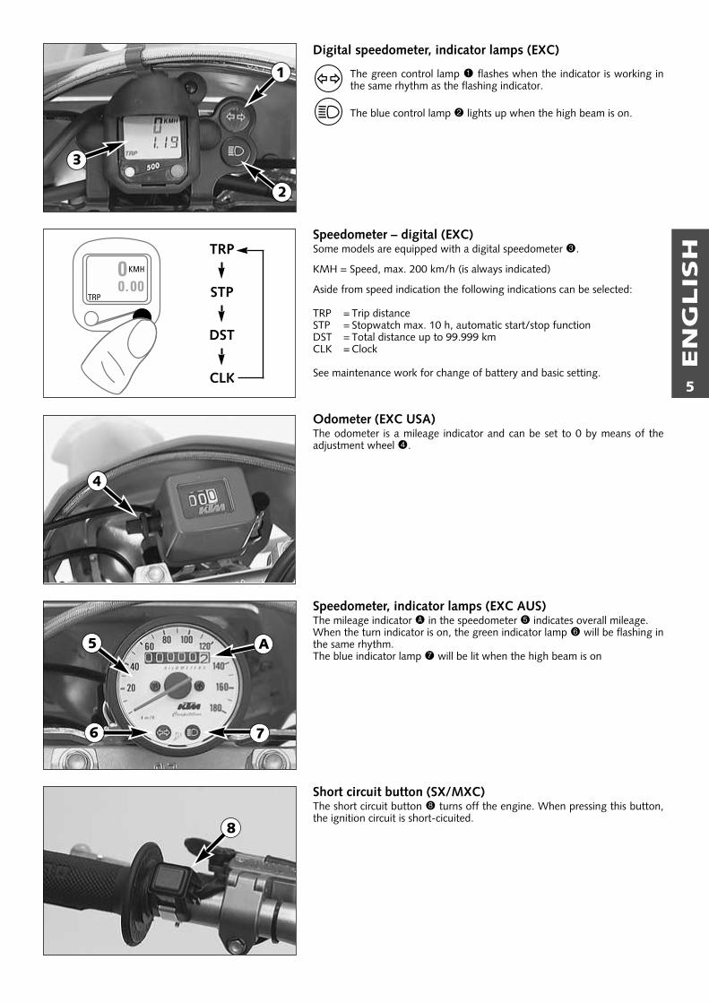
Digital speedometer, indicator lamps (EXC)
The green control lamp 1 flashes when the indicator is working inthe same rhythm as the flashing indicator.
The blue control lamp 2 lights up when the high beam is on.
Speedometer – digital (EXC)Some models are equipped with a digital speedometer 3.
KMH = Speed, max. 200 km/h (is always indicated)
Aside from speed indication the following indications can be selected:
TRP = Trip distanceSTP = Stopwatch max. 10 h, automatic start/stop functionDST = Total distance up to 99.999 kmCLK = Clock
See maintenance work for change of battery and basic setting.
Odometer (EXC USA)The odometer is a mileage indicator and can be set to 0 by means of theadjustment wheel 4.
Speedometer, indicator lamps (EXC AUS)The mileage indicator A in the speedometer 5 indicates overall mileage.When the turn indicator is on, the green indicator lamp 6 will be flashing inthe same rhythm.The blue indicator lamp 7 will be lit when the high beam is on
Short circuit button (SX/MXC)The short circuit button 8 turns off the engine. When pressing this button,the ignition circuit is short-cicuited.
1
2
6
8
TRP
STP
DST
CLK
3
A5
7
4
EN
GLIS
H
6
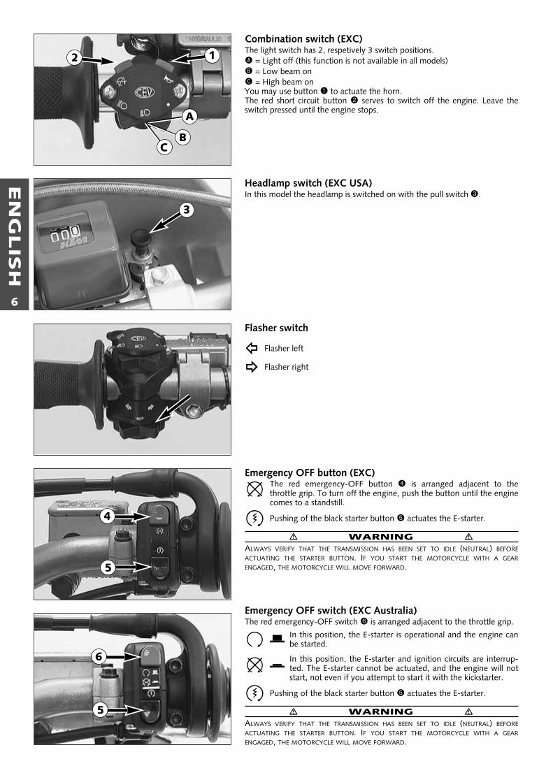
Combination switch (EXC)The light switch has 2, respetively 3 switch positions.A = Light off (this function is not available in all models)B = Low beam onC = High beam onYou may use button 1 to actuate the horn.The red short circuit button 2 serves to switch off the engine. Leave theswitch pressed until the engine stops.
Headlamp switch (EXC USA)In this model the headlamp is switched on with the pull switch 3.
Flasher switch
Flasher left
Flasher right
Emergency OFF button (EXC)The red emergency-OFF button 4 is arranged adjacent to thethrottle grip. To turn off the engine, push the button until the enginecomes to a standstill.
Pushing of the black starter button 5 actuates the E-starter.
� WARNING �ALWAYS VERIFY THAT THE TRANSMISSION HAS BEEN SET TO IDLE (NEUTRAL) BEFOREACTUATING THE STARTER BUTTON. IF YOU START THE MOTORCYCLE WITH A GEARENGAGED, THE MOTORCYCLE WILL MOVE FORWARD.
Emergency OFF switch (EXC Australia)The red emergency-OFF switch 6 is arranged adjacent to the throttle grip.
In this position, the E-starter is operational and the engine canbe started.
In this position, the E-starter and ignition circuits are interrup-ted. The E-starter cannot be actuated, and the engine will notstart, not even if you attempt to start it with the kickstarter.
Pushing of the black starter button 5 actuates the E-starter.
� WARNING �ALWAYS VERIFY THAT THE TRANSMISSION HAS BEEN SET TO IDLE (NEUTRAL) BEFOREACTUATING THE STARTER BUTTON. IF YOU START THE MOTORCYCLE WITH A GEARENGAGED, THE MOTORCYCLE WILL MOVE FORWARD.
2
A
BC
1
3
5
4
5
6
EN
GLIS
H
7
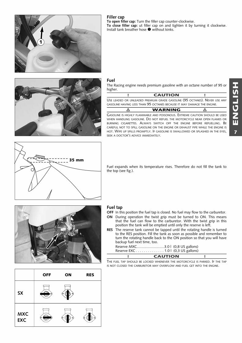
Filler capTo open filler cap: Turn the filler cap counter-clockwise.To close filler cap: ut filler cap on and tighten it by turning it clockwise.Install tank breather hose 1 without kinks.
FuelThe Racing engine needs premium gasoline with an octane number of 95 orhigher.
! CAUTION !USE LEADED OR UNLEADED PREMIUM GRADE GASOLINE (95 OCTANES). NEVER USE ANYGASOLINE HAVING LESS THAN 95 OCTANES BECAUSE IT MAY DAMAGE THE ENGINE.
� WARNING �GASOLINE IS HIGHLY FLAMMABLE AND POISONOUS. EXTREME CAUTION SHOULD BE USEDWHEN HANDLING GASOLINE. DO NOT REFUEL THE MOTORCYCLE NEAR OPEN FLAMES ORBURNING CIGARETTES. ALWAYS SWITCH OFF THE ENGINE BEFORE REFUELLING. BECAREFUL NOT TO SPILL GASOLINE ON THE ENGINE OR EXHAUST PIPE WHILE THE ENGINE ISHOT. WIPE UP SPILLS PROMPTLY. IF GASOLINE IS SWALLOWED OR SPLASHED IN THE EYES,SEEK A DOCTOR’S ADVICE IMMEDIATELY.
Fuel expands when its temperature rises. Therefore do not fill the tank tothe top (see fig.).
Fuel tapOFF In this position the fuel tap is closed. No fuel may flow to the carburetor.ON During operation the twist grip must be turned to ON. This means
that the fuel can flow to the carburetor. With the twist grip in thisposition the tank will be emptied until only the reserve is left.
RES The reserve tank cannot be tapped until the rotating handle is turnedto the RES position. Fill the tank as soon as possible and remember toturn the rotating handle back to the ON position so that you will havebackup fuel next time, too. Reserve MXC...........................3.0 l (0,8 US gallons)Reserve EXC . . . . . . . . . . . . . . 1.0 l (0,3 US gallons)
! CAUTION !THE FUEL TAP SHOULD BE LOCKED WHENEVER THE MOTORCYCLE IS PARKED. IF THE TAPIS NOT CLOSED THE CARBURETOR MAY OVERFLOW AND FUEL GET INTO THE ENGINE.
35 mm
1
ON RESOFF
SX
MXCEXC
EN
GLIS
H
8
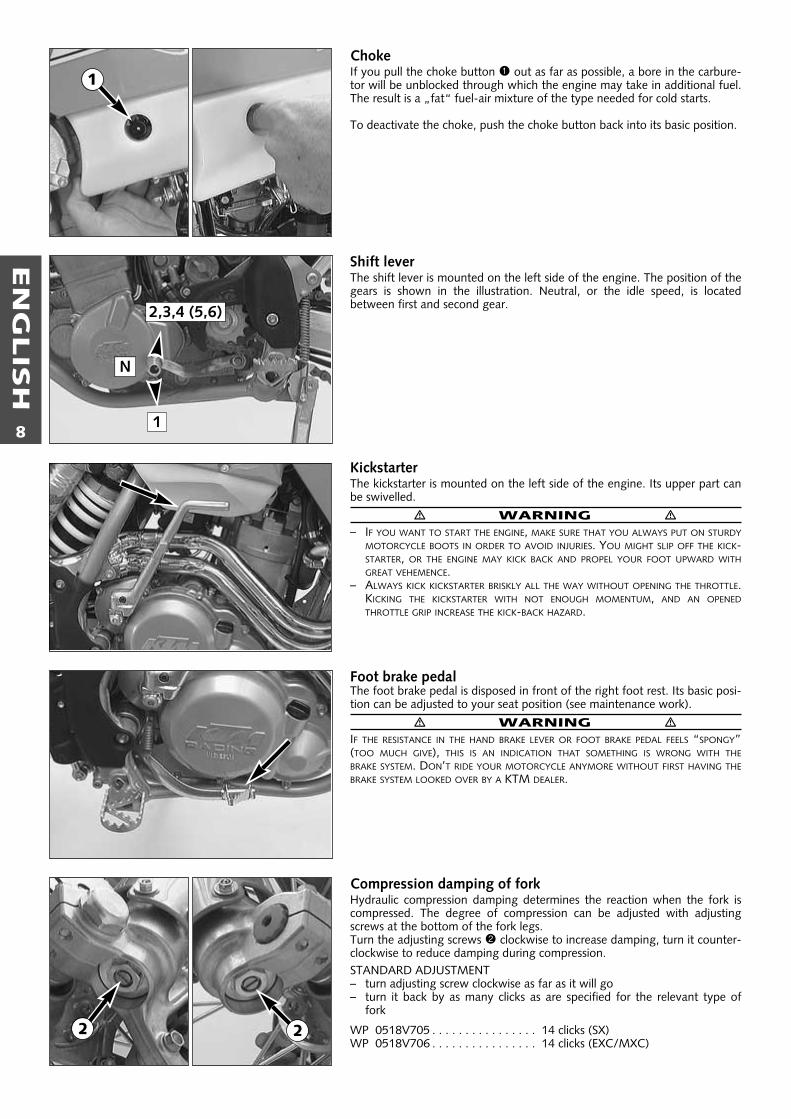
ChokeIf you pull the choke button 1 out as far as possible, a bore in the carbure-tor will be unblocked through which the engine may take in additional fuel.The result is a „fat“ fuel-air mixture of the type needed for cold starts.
To deactivate the choke, push the choke button back into its basic position.
Shift leverThe shift lever is mounted on the left side of the engine. The position of thegears is shown in the illustration. Neutral, or the idle speed, is located between first and second gear.
KickstarterThe kickstarter is mounted on the left side of the engine. Its upper part canbe swivelled.
� WARNING �– IF YOU WANT TO START THE ENGINE, MAKE SURE THAT YOU ALWAYS PUT ON STURDY
MOTORCYCLE BOOTS IN ORDER TO AVOID INJURIES. YOU MIGHT SLIP OFF THE KICK-STARTER, OR THE ENGINE MAY KICK BACK AND PROPEL YOUR FOOT UPWARD WITHGREAT VEHEMENCE.
– ALWAYS KICK KICKSTARTER BRISKLY ALL THE WAY WITHOUT OPENING THE THROTTLE.KICKING THE KICKSTARTER WITH NOT ENOUGH MOMENTUM, AND AN OPENEDTHROTTLE GRIP INCREASE THE KICK-BACK HAZARD.
Foot brake pedalThe foot brake pedal is disposed in front of the right foot rest. Its basic posi-tion can be adjusted to your seat position (see maintenance work).
� WARNING �IF THE RESISTANCE IN THE HAND BRAKE LEVER OR FOOT BRAKE PEDAL FEELS “SPONGY”(TOO MUCH GIVE), THIS IS AN INDICATION THAT SOMETHING IS WRONG WITH THEBRAKE SYSTEM. DON’T RIDE YOUR MOTORCYCLE ANYMORE WITHOUT FIRST HAVING THEBRAKE SYSTEM LOOKED OVER BY A KTM DEALER.
Compression damping of forkHydraulic compression damping determines the reaction when the fork iscompressed. The degree of compression can be adjusted with adjusting screws at the bottom of the fork legs.Turn the adjusting screws 2 clockwise to increase damping, turn it counter-clockwise to reduce damping during compression.STANDARD ADJUSTMENT– turn adjusting screw clockwise as far as it will go– turn it back by as many clicks as are specified for the relevant type of
fork
WP 0518V705 . . . . . . . . . . . . . . . . 14 clicks (SX)WP 0518V706 . . . . . . . . . . . . . . . . 14 clicks (EXC/MXC)
2,3,4 (5,6)
1
N
1
2 2
EN
GLIS
H
9
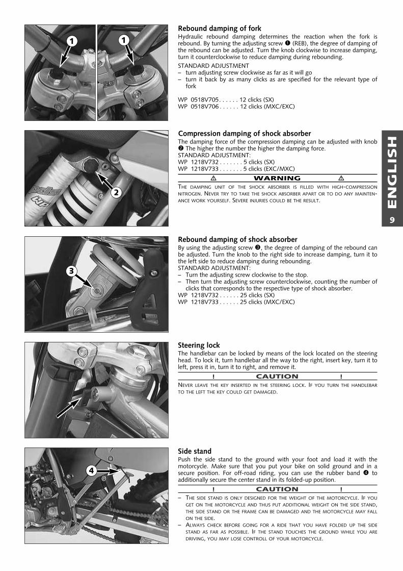
Rebound damping of forkHydraulic rebound damping determines the reaction when the fork is rebound. By turning the adjusting screw 1 (REB), the degree of damping ofthe rebound can be adjusted. Turn the knob clockwise to increase damping,turn it counterclockwise to reduce damping during rebounding.STANDARD ADJUSTMENT– turn adjusting screw clockwise as far as it will go– turn it back by as many clicks as are specified for the relevant type of
fork
WP 0518V705. . . . . . 12 clicks (SX)WP 0518V706 . . . . . . 12 clicks (MXC/EXC)
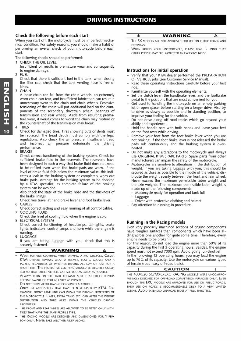
Compression damping of shock absorber The damping force of the compression damping can be adjusted with knob2 The higher the number the higher the damping force.STANDARD ADJUSTMENT:WP 1218V732 . . . . . . . 5 clicks (SX)WP 1218V733 . . . . . . . 5 clicks (EXC/MXC)
� WARNING �THE DAMPING UNIT OF THE SHOCK ABSORBER IS FILLED WITH HIGH-COMPRESSIONNITROGEN. NEVER TRY TO TAKE THE SHOCK ABSORBER APART OR TO DO ANY MAINTEN-ANCE WORK YOURSELF. SEVERE INJURIES COULD BE THE RESULT.
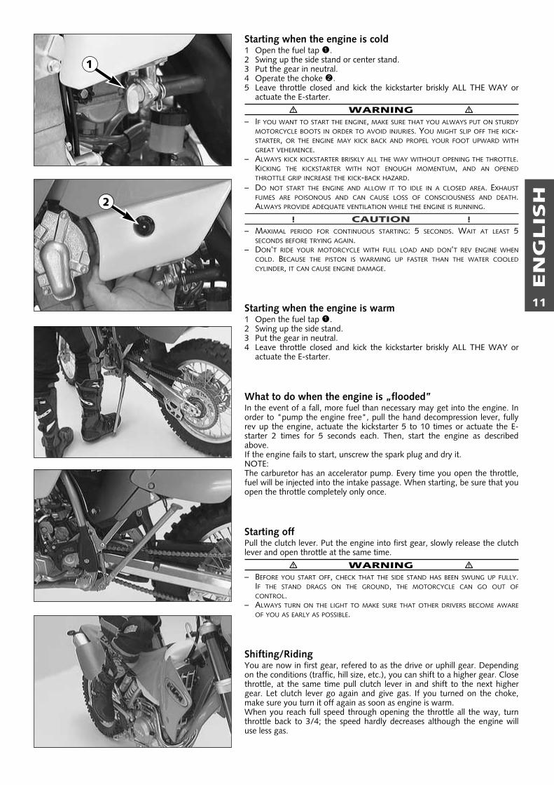
Rebound damping of shock absorber By using the adjusting screw 3, the degree of damping of the rebound canbe adjusted. Turn the knob to the right side to increase damping, turn it tothe left side to reduce damping during rebounding.STANDARD ADJUSTMENT:– Turn the adjusting screw clockwise to the stop.– Then turn the adjusting screw counterclockwise, counting the number of
clicks that corresponds to the respective type of shock absorber.WP 1218V732 . . . . . . 25 clicks (SX)WP 1218V733 . . . . . . 25 clicks (MXC/EXC)
Steering lock The handlebar can be locked by means of the lock located on the steeringhead. To lock it, turn handlebar all the way to the right, insert key, turn it toleft, press it in, turn it to right, and remove it.
! CAUTION !NEVER LEAVE THE KEY INSERTED IN THE STEERING LOCK. IF YOU TURN THE HANDLEBARTO THE LEFT THE KEY COULD GET DAMAGED.
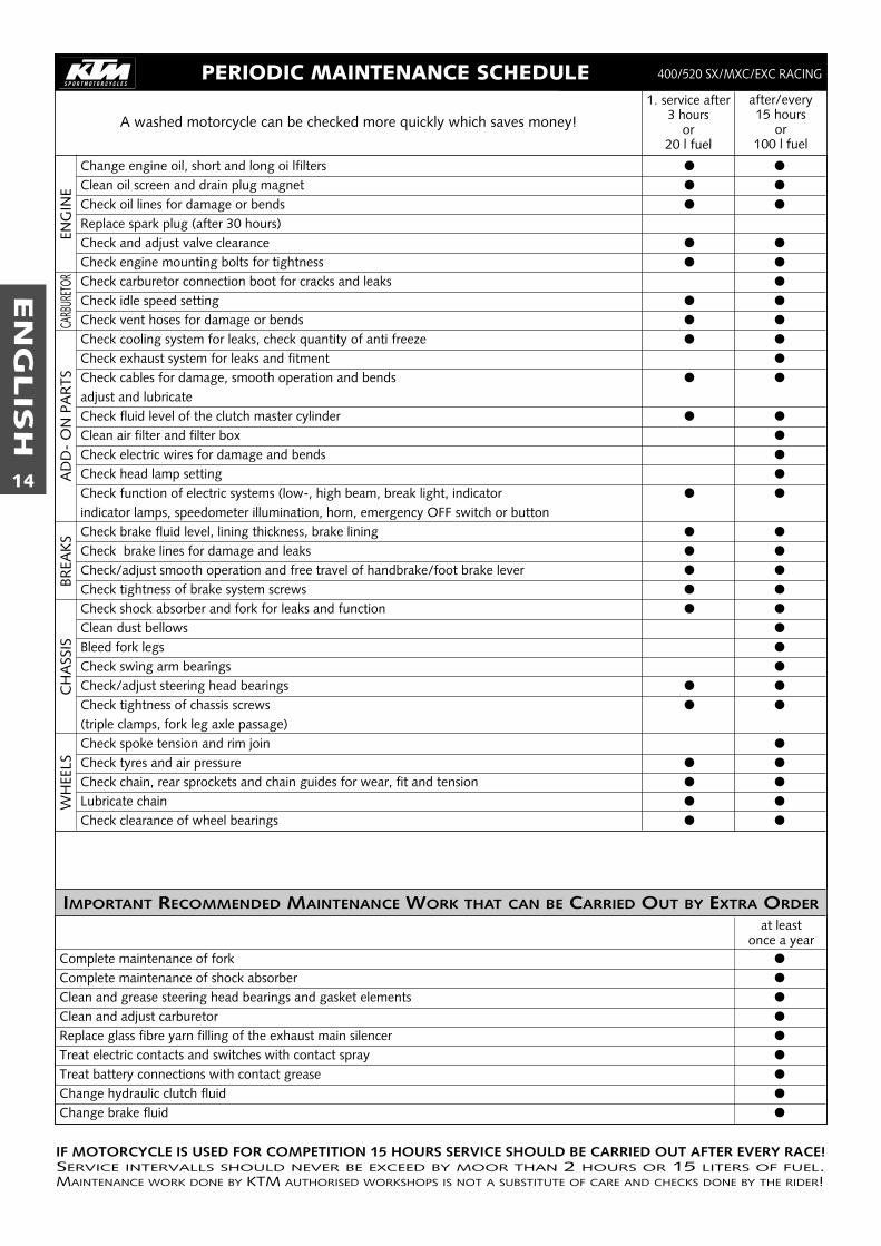
Side standPush the side stand to the ground with your foot and load it with themotorcycle. Make sure that you put your bike on solid ground and in asecure position. For off-road riding, you can use the rubber band 4 toadditionally secure the center stand in its folded-up position.
! CAUTION !– THE SIDE STAND IS ONLY DESIGNED FOR THE WEIGHT OF THE MOTORCYCLE. IF YOU
GET ON THE MOTORCYCLE AND THUS PUT ADDITIONAL WEIGHT ON THE SIDE STAND,THE SIDE STAND OR THE FRAME CAN BE DAMAGED AND THE MOTORCYCLE MAY FALLON THE SIDE.
– ALWAYS CHECK BEFORE GOING FOR A RIDE THAT YOU HAVE FOLDED UP THE SIDESTAND AS FAR AS POSSIBLE. IF THE STAND TOUCHES THE GROUND WHILE YOU AREDRIVING, YOU MAY LOSE CONTROLL OF YOUR MOTORCYCLE.
1 1
2
3
4
EN
GLIS
H
10
DRIVING INSTRUCTIONS
� WARNING �– THE SX MODELS ARE NOT APPROVED FOR USE ON PUBLIC ROADS AND
FREEWAYS.– WHEN RIDING YOUR MOTORCYCLE, PLEASE BEAR IN MIND THAT
OTHER PEOPLE MAY FEEL MOLESTED BY EXCESSIVE NOISE.
Instructions for initial operation– Verify that your KTM dealer performed the PREPARATION
OF VEHICLE jobs (see Customer Service Manual).– Read these operating instructions carefully before your first
ride.– Familiarize yourself with the operating elements.– Set the clutch lever, the handbrake lever, and the footbrake
pedal to the positions that are most convenient for you.– Get used to handling the motorcycle on an empty parking
lot or open space, before starting on a longer drive. Also tryto drive as slowly as possible and in standing position, toimprove your feeling for the vehicle.
– Do not drive along off-road tracks which go beyond yourabitily and experience.
– Hold the handle bars with both hands and leave your feeton the foot rests while driving.
– Remove your foot from the foot brake lever when you arenot braking. If the foot brake lever is not released the brakepads rub continuously and the braking system is over-heated.
– Do not make any alterations to the motorcycle and alwaysuse ORIGINAL KTM SPARE PARTS. Spare parts from othermanufacturers can impair the safety of the motorcycle.
– Motorcycles are sensitive to alterations in the distribution ofweight. If you are taking luggage with you, this should besecured as close as possible to the middle of the vehicle; dis-tribute the weight evenly between the front and rear wheel.Never exceed the maximum permissible laden weight andthe axle weights. The maximum permissible laden weight ismade up of the following components:– Motorcycle ready for operation and tank full– Luggage– Driver with protective clothing and helmet.
– Pay attention to running-in procedure.
Running in the Racing modelsEven very precisely machined sections of engine componentshave rougher surfaces than components which have been sli-ding across one another for quite some time. Therefore, everyengine needs to be broken in. For this reason, do not load the engine more than 50% of itscapacity during the first 3 operating hours. Besides, the enginespeed must not exceed 7000 rpm. Avoid going full-throttle!In the following 12 operating hours, you may load the engineup to 75% of its capacity. Use the motorcycle on various typesof terrain (road, easy off-road trails).
! CAUTION !THE 400/520 SC/MXC/EXC RACING MODELS WERE UNCOMPRO-MISINGLY DESIGNED FOR OFF-ROAD COMPETITION PURPOSES ONLY. EVENTHOUGH THE EXC MODELS ARE APPROVED FOR USE ON PUBLIC ROADS,THEIR USE ON ROADS IS RECOMMENDABLE ONLY TO A VERY LIMITEDEXTENT. AVOID EXTENDED ON-ROAD RIDES AT FULL THROTTLE.
Check the following before each startWhen you start off, the motorcycle must be in perfect mecha-nical condition. For safety reasons, you should make a habit ofperforming an overall check of your motorcycle before eachstart.The following checks should be performed:1 CHECK THE OIL LEVEL
Insufficient oil results in premature wear and consequentlyto engine damage.
2 FUELCheck that there is sufficient fuel in the tank; when closingthe filler cap, check that the tank venting hose is free ofkinks.
3 CHAINA loose chain can fall from the chain wheels; an extremelyworn chain can tear, and insufficient lubrication can result inunnecessary wear to the chain and chain wheels. Excessivetensioning of the chain will put additional load on the com-ponents of the secondary drivetrain (chain, bearings oftransmission and rear wheel). Aside from resulting prema-ture wear, if worst comes to worst the chain may rupture orthe countershaft of the transmission may break.
4 TIRESCheck for damaged tires. Tires showing cuts or dents mustbe replaced. The tread depth must comply with the legalregulations. Also check the air pressure. Insufficient treadand incorrect air pressure deteriorate the driving performance.
5 BRAKESCheck correct functioning of the braking system. Check forsufficient brake fluid in the reservoir. The reservoirs havebeen designed in such a way that brake fluid does not needto be refilled even when the brake pads are worn. If thelevel of brake fluid falls below the minimum value, this indi-cates a leak in the braking system or completely worn outbrake pads. Arrange for the braking system to be checkedby a KTM specialist, as complete failure of the brakingsystem can be avoided.Also check the state of the brake hose and the thickness ofthe brake linings.Check free travel at hand brake lever and foot brake lever.
6 CABLESCheck correct setting and easy running of all control cables.
7 COOLING FLUIDCheck the level of cooling fluid when the engine is cold.
8 ELECTRICAL SYSTEMCheck correct functioning of headlamps, tail-lights, brakelights, indicators, control lamps and horn while the engine isrunning.
9 LUGGAGEIf you are taking luggage with you, check that this is securely fastened.
� WARNING �– WEAR SUITABLE CLOTHING WHEN DRIVING A MOTORCYCLE. CLEVER
KTM DRIVERS ALWAYS WEAR A HELMET, BOOTS, GLOVES AND AJACKET, REGARDLESS OF WHETHER DRIVING ALL DAY OR JUST FOR ASHORT TRIP. THE PROTECTIVE CLOTHING SHOULD BE BRIGHTLY COLO-RED SO THAT OTHER VEHICLE CAN SEE YOU AS EARLY AS POSSIBLE.
– ALWAYS TURN ON THE LIGHT TO MAKE SURE THAT OTHER DRIVERSBECOME AWARE OF YOU AS EARLY AS POSSIBLE.
– DO NOT DRIVE AFTER HAVING CONSUMED ALCOHOL.– ONLY USE ACCESSORIES THAT HAVE BEEN RELEASED BY KTM. FOR
EXAMPLE, FRONT PANELLING CAN IMPAIR THE DRIVING PROPERTIES OFTHE MOTORCYCLE. CASES, EXTRA TANKS ETC. CAN ALTER THE WEIGHTDISTRIBUTION AND THUS ALSO IMPAIR THE VEHICLES DRIVINGPROPERTIES.
– THE FRONT AND REAR WHEEL ARE ALLOWED TO BE FITTED ONLY WITHTIRES THAT HAVE THE SAME PROFILE TYPE.
– THE RACING MODELS ARE DESIGNED AND DIMENSIONED FOR 1 PER-SON ONLY. NEVER TAKE ANOTHER RIDER ALONG.
EN
GLIS
H
11
Starting when the engine is cold1 Open the fuel tap 1.2 Swing up the side stand or center stand.3 Put the gear in neutral.4 Operate the choke 2.5 Leave throttle closed and kick the kickstarter briskly ALL THE WAY or
actuate the E-starter.
� WARNING �– IF YOU WANT TO START THE ENGINE, MAKE SURE THAT YOU ALWAYS PUT ON STURDY
MOTORCYCLE BOOTS IN ORDER TO AVOID INJURIES. YOU MIGHT SLIP OFF THE KICK-STARTER, OR THE ENGINE MAY KICK BACK AND PROPEL YOUR FOOT UPWARD WITHGREAT VEHEMENCE.
– ALWAYS KICK KICKSTARTER BRISKLY ALL THE WAY WITHOUT OPENING THE THROTTLE.KICKING THE KICKSTARTER WITH NOT ENOUGH MOMENTUM, AND AN OPENEDTHROTTLE GRIP INCREASE THE KICK-BACK HAZARD.
– DO NOT START THE ENGINE AND ALLOW IT TO IDLE IN A CLOSED AREA. EXHAUSTFUMES ARE POISONOUS AND CAN CAUSE LOSS OF CONSCIOUSNESS AND DEATH.ALWAYS PROVIDE ADEQUATE VENTILATION WHILE THE ENGINE IS RUNNING.
! CAUTION !– MAXIMAL PERIOD FOR CONTINUOUS STARTING: 5 SECONDS. WAIT AT LEAST 5
SECONDS BEFORE TRYING AGAIN.– DON’T RIDE YOUR MOTORCYCLE WITH FULL LOAD AND DON’T REV ENGINE WHEN
COLD. BECAUSE THE PISTON IS WARMING UP FASTER THAN THE WATER COOLEDCYLINDER, IT CAN CAUSE ENGINE DAMAGE.
Starting when the engine is warm1 Open the fuel tap 1.2 Swing up the side stand.3 Put the gear in neutral.4 Leave throttle closed and kick the kickstarter briskly ALL THE WAY or
actuate the E-starter.
What to do when the engine is „flooded”In the event of a fall, more fuel than necessary may get into the engine. Inorder to "pump the engine free", pull the hand decompression lever, fullyrev up the engine, actuate the kickstarter 5 to 10 times or actuate the E-starter 2 times for 5 seconds each. Then, start the engine as describedabove.If the engine fails to start, unscrew the spark plug and dry it.NOTE:The carburetor has an accelerator pump. Every time you open the throttle,fuel will be injected into the intake passage. When starting, be sure that youopen the throttle completely only once.
Starting offPull the clutch lever. Put the engine into first gear, slowly release the clutchlever and open throttle at the same time.
� WARNING �– BEFORE YOU START OFF, CHECK THAT THE SIDE STAND HAS BEEN SWUNG UP FULLY.
IF THE STAND DRAGS ON THE GROUND, THE MOTORCYCLE CAN GO OUT OFCONTROL.
– ALWAYS TURN ON THE LIGHT TO MAKE SURE THAT OTHER DRIVERS BECOME AWAREOF YOU AS EARLY AS POSSIBLE.
Shifting/RidingYou are now in first gear, refered to as the drive or uphill gear. Dependingon the conditions (traffic, hill size, etc.), you can shift to a higher gear. Closethrottle, at the same time pull clutch lever in and shift to the next highergear. Let clutch lever go again and give gas. If you turned on the choke,make sure you turn it off again as soon as engine is warm.When you reach full speed through opening the throttle all the way, turnthrottle back to 3/4; the speed hardly decreases although the engine willuse less gas.
1
2

EN
GLIS
H
12
Only give as much gas as the engine can handle. Throughquick and high reving of throttle, the fuel usage increases.By shifting down, use the brakes if necessary and close throttleat the same time. Pull clutch lever and shift down to the nextgear. Let clutch lever go slowely and open throttle or shiftdown again.
NOTE:DEDICATED TO NOTHING BUT OFFROAD RACING, 400/520SX/MXC/EXC RACING MODELS MAKE NO COMPROMISES IN THEIRDESIGN. AS SUCH, THEY DO NOT INCLUDE ANY RADIATOR FAN, AND THESIZE OF THE RADIATOR IS DIMENSIONED FOR OPTIMUM ERGONOMICS. IN NORMAL RACING, THE COOLING SYSTEM IS SUFFICIENT. IF YOU USE YOUR MOTORBIKE IN OTHER CONDITIONS, PLEASE NOTE THAT– THE E-STARTER ALLOWS YOU TO START MXC/EXC RACING MODELS
AGAIN AT ANY TIME. THEREFORE, TURN OFF THE ENGINE IF YOUINTEND TO RUN YOUR MOTORCYCLE IN IDLE OR AT STANDSTILL FORLONGER PERIODS OF TIME (MORE THAN 2 MINUTES).
– AVOID LETTING THE CLUTCH SLIP FREQUENTLY AND FOR EXTENDEDPERIODS. THIS WOULD CAUSE THE ENGINE OIL TO HEAT UP, THEREBYHEATING UP THE ENGINE AND THE COOLING SYSTEM. RATHER, YOUSHOULD DRIVE AT LOW SPEEDS (4-STROKE STYLE - LETTING THEENGINE PULL YOU) AND NOT AT HIGH SPEEDS NOT BY LETTING THECLUTCH SLIP (2-STROKE STYLE).
� WARNING �– OBSERVE THE TRAFFIC REGULATIONS, DRIVE DEFENSIVELY AND TRYING
TO LOOK AHEAD AS FAR AS POSSIBLE SO THAT ANY HAZARDS CAN BERECOGNIZED AS EARLY AS POSSIBLE.
– ADJUST YOUR DRIVING SPEED ACCORDING TO THE CONDITIONS ANDYOUR DRIVING SKILLS.
– DRIVE CAREFULLY UN UNKNOWN ROADS OR ON UNFAMILIAR TRIALS.– WHEN DRIVING OFF-ROAD, ALWAYS HAVE A FRIEND ON A SECOND
MOTORCYCLE TO KEEP YOU COMPANY, SO THAT YOU CAN HELP EACHOTHER SHOULD DIFFICULTIES ARISE.
– REPLACE HELMET VISOR OR GOGGLE LENS WHEN SCRATCHED ORDAMAGED. IF BRIGHT LIGHT SHINES THROUGH A SCRATCHED VISOR ORLENS, THE OPERATOR WILL BE BLINDED.
– AFTER FALLING WITH THE MOTORCYCLE, CHECK ALL FUNCTIONSTHOROUGHLY BEFORE STARTING UP OPERATIONS AGAIN.
– A TWISTED HANDLEBAR MUST ALWAYS BE REPLACED. DO NOT ADJUSTTHE HANDLEBAR, IT WILL LOSE STA-BILITY.
! CAUTION !– HIGH RPM RATES WHEN THE ENGINE IS COLD HAVE AN ADVERSE
EFFECT ON THE LIFE OF YOUR ENGINE. WE RECOMMEND YOU RUNTHE ENGINE IN A MODERATE RPM RANGE FOR A FEW MILES GIVING ITA CHANCE TO WARM UP. AFTER THAT NO FURTHER PRECAUTIONS INTHIS RESPECT NEED BE TAKEN. THE ENGINE HAS REACHED ITS OPERA-TING TEMPERATURE AS SOON AS THE RADIATORS BECOME WARM.
– NEVER HAVE THE THROTTLE WIDE OPEN WHEN CHANGING DOWN TOA LOWER GEAR. THE ENGINE WILL OVER-REV, DAMAGING THE VALVES.IN ADDITION, THE REAR WHEEL LOCKS SO THAT THE MOTORCYCLECAN EASILY GET OUT OF CONTROL.
– IF ANY ABNORMAL VIBRATIONS OCCUR WHILE DRIVING, CHECK THATTHE ENGINE FASTENING BOLTS ARE TIGHT.
– IN THE EVENT THAT, WHILE RIDING ON YOUR MOTORCYCLE, YOUNOTICE ANY UNUSUAL OPERATION-RELATED NOISE, STOP IMMEDIA-TELY, TURN THE ENGINE OFF, AND CONTACT AN AUTHORIZED KTMDEALER.
– NEVER START YOUR MOTORCYCLE IF NO AIR FILTER HAS BEEN MOUN-TED; OTHERWISE, DUST AND DIRT MAY ENTER THE ENGINE AND CAUSEINCREASED WEAR.
BrakingClose throttle and apply the hand and foot brakes at the sametime. When driving on sandy, wet or slippery ground usemainly the rear wheel brake. Always brake with feeling,blocking wheels can cause you to skid or fall. Also changedown to lower gears depending on your speed.When driving down hill, use the braking effect of the engine.Change down one or two gears but do not overspeed theengine. In this way, you will not need to brake so much andthe brakes will not overheat.
� WARNING �– IN CASE OF RAIN, AFTER WASHING THE MOTORCYCLE, AFTER RIDES
THROUGH WATER AND IN CASE OF RIDES ON WET OFF-ROAD TRACKS,HUMID OR DIRTY BRAKE DISCS CAN DELAY THE BRAKING EFFECT. THEBRAKES MUST BE PULLED UNTIL THEY ARE DRY OR CLEAN.
– RIDES ON SALT-STREWED OR DIRTY ROADS CAN ALSO DELAY THE BRA-KING EFFECT. THE BRAKES MUST BE PULLED UNTIL THEY ARE CLEAN.
– DIRTY BRAKE DISCS CAUSE INCREASED TEAR OF BRAKE PADS ANDBRAKE DISCS.
– WHEN YOU BRAKE, THE BRAKE DISCS, BRAKE PADS, BRAKE CALIPERAND BRAKE FLUID HEAT UP. THE HOTTER THESE PARTS GET, THE WEA-KER THE BREAKING EFFECT. IN EXTREME CASES, THE ENTIRE BRAKINGSYSTEM CAN FAIL.
Stopping and parkingApply the brakes fully and put the engine into neutral. To turnoff the engine, push the short-circuit button or the emergency-OFF button with the engine at idling speed until the enginestops. Turn the fuel tap to the OFF position, park on an areawhere the ground is firm, and lock the motorcycle.
� WARNING �– NEVER LEAVE YOUR MOTORCYCLE WITHOUT SUPERVISION IF THE
ENGINE IS RUNNING.– MOTORCYCLE ENGINES PRODUCE A GREAT AMOUNT OF HEAT WHILE
RUNNING. THE ENGINE, EXHAUST PIPE, MUFFLER, BRAKE ROTORS, ANDSHOCK ABSORBERS CAN BECOME VERY HOT. DO NOT TOUCH ANY OFTHESE PARTS AFTER OPERATING THE MOTORCYCLE, AND TAKE CARE TOPARK IT WHERE PEDESTRIANS ARE NOT LIKELY TO TOUCH IT AND GETBURNED.
! CAUTION !– NEVER USE THE HAND DECOMPRESSION LEVER TO TURN OFF THE
ENGINE. RATHER, USE THE SHORT-CIRCUIT BUTTON OR THE EMER-GENCY-OFF BUTTON.
– CLOSE THE FUEL TAP WHEN LEAVING YOUR VEHICLE.OTHERWISE THECARBURETTOR CAN FLOOD AND FUEL WILL ENTER THE ENGINE.
– NEVER PARK YOUR MOTORCYCLE IN PLACES WHERE THERE EXIST FIREHAZARDS DUE TO DRY GRASS OR OTHER EASILY FLAMMABLEMATERIALS.
NOTE REGARDING THE SIDE STAND:Use your foot to kick side stand forward up to the stop andlean the motorcycle sideways. Make sure that the ground issolid and that your motorcycle is standing securely. Just incase, you can shift into first gear.
! CAUTION !THE SIDE STAND IS DESIGNED TO BEAR ONLY THE LOAD OF THEMOTORCYCLE. THE SIDE STAND AND/OR THE FRAME CAN BE DAMAGEDAND THE MOTORCYCLE CAN FALL OVER IF YOU MOUNT THE MOTOR-CYCLE, THUS PUTTING AN ADDITIONAL LOAD ON THE SIDE STAND.

EN
GLIS
H
13
EN
GLIS
H
14
PERIODIC MAINTENANCE SCHEDULE1. service after
3 hoursor
20 l fuel
after/every15 hours
or100 l fuel
IF MOTORCYCLE IS USED FOR COMPETITION 15 HOURS SERVICE SHOULD BE CARRIED OUT AFTER EVERY RACE!SERVICE INTERVALLS SHOULD NEVER BE EXCEED BY MOOR THAN 2 HOURS OR 15 LITERS OF FUEL.MAINTENANCE WORK DONE BY KTM AUTHORISED WORKSHOPS IS NOT A SUBSTITUTE OF CARE AND CHECKS DONE BY THE RIDER!
A washed motorcycle can be checked more quickly which saves money!
Change engine oil, short and long oi lfilters � �
Clean oil screen and drain plug magnet � �
Check oil lines for damage or bends � �
Replace spark plug (after 30 hours)Check and adjust valve clearance � �
Check engine mounting bolts for tightness � �
Check carburetor connection boot for cracks and leaks �
Check idle speed setting � �
Check vent hoses for damage or bends � �
Check cooling system for leaks, check quantity of anti freeze � �
Check exhaust system for leaks and fitment �
Check cables for damage, smooth operation and bends � �
adjust and lubricateCheck fluid level of the clutch master cylinder � �
Clean air filter and filter box �
Check electric wires for damage and bends �
Check head lamp setting �
Check function of electric systems (low-, high beam, break light, indicator � �
indicator lamps, speedometer illumination, horn, emergency OFF switch or buttonCheck brake fluid level, lining thickness, brake lining � �
Check brake lines for damage and leaks � �
Check/adjust smooth operation and free travel of handbrake/foot brake lever � �
Check tightness of brake system screws � �
Check shock absorber and fork for leaks and function � �
Clean dust bellows �
Bleed fork legs �
Check swing arm bearings �
Check/adjust steering head bearings � �
Check tightness of chassis screws � �
(triple clamps, fork leg axle passage)Check spoke tension and rim join �
Check tyres and air pressure � �
Check chain, rear sprockets and chain guides for wear, fit and tension � �
Lubricate chain � �
Check clearance of wheel bearings � �
IMPORTANT RECOMMENDED MAINTENANCE WORK THAT CAN BE CARRIED OUT BY EXTRA ORDER
Complete maintenance of fork �
Complete maintenance of shock absorber �
Clean and grease steering head bearings and gasket elements �
Clean and adjust carburetor �
Replace glass fibre yarn filling of the exhaust main silencer �
Treat electric contacts and switches with contact spray �
Treat battery connections with contact grease �
Change hydraulic clutch fluid �
Change brake fluid �
WH
EELS
CH
ASS
ISBR
EAK
SA
DD
- O
N P
AR
TSCA
RBUR
ETOR
ENG
INE
400/520 SX/MXC/EXC RACING
at leastonce a year

EN
GLIS
H
15
SUPPLEMENTARY MAINTENANCE INSTRUCTIONS FOR THE 400/520 RACING ENGINE(ADDITIONAL ORDER FOR KTM WORKSHOP)
hourshours 400 SX400 SX 400 MXC/EXC400 MXC/EXC 520 SX520 SX 520 MXC/EX520 MXC/EX
15 Small Maintenance Kit - Small Maintenance Kit -
30 Small Maintenance Kit Small Maintenance Kit Small Maintenance Kit Small Maintenance Kit
45 Large Maintenance Kit - Large Maintenance Kit -
60 Small Maintenance Kit Large Maintenance Kit Small Maintenance Kit Large Maintenance Kit
75 Small Maintenance Kit - Small Maintenance Kit -
90 Large Maintenance Kit Small Maintenance Kit Large Maintenance Kit Small Maintenance Kit
105 Small Maintenance Kit - Small Maintenance Kit -
120 Small Maintenance Kit Large Maintenance Kit Small Maintenance Kit Large Maintenance Kit
IMPORTANT CHECKS AND MAINTENANCE TO BE CARRIED OUT BY THE RIDER
Check oil level �
Check break fluid level �
Check break pads for wear �
Check lights for function �
Check horn for function �
Lubricate and adjust cables and nipples �
Bleed fork legs regulary �
Remove and clean dust bellows regulary �
Clean and lubricate chain, check tension and adjust if necessary � �
Clean air filter and filter box �
Check tyres for pressure and wear �
Check cooling fluid level �
Check fuel lines for leaks �
Empty and clean float chamber �
Check all control elements for smooth operation �
Check break performance � �
Treat blank metal parts (with the exception of brake and exhaust system) �
with wax-based anti corrosion agentTreat ignition and steering locks and light switches with contact spray �
Check tightness of screws, nuts and hose clamps regular �
For cross-country use
After everycleaning
Befor eachstart
EN
GLIS
H
16
� WARNING �
MAINTENANCE AND ADJUSTING WORK MARKED WITH AN ASTERISK (*) REQUIRES EXPERT SKILLS AND TECHNICAL KNOW-HOW. FOR YOUR OWN SAFETY, ALWAYS HAVE SUCH WORK PERFORMED BY A SPECIALIZEDKTM DEALER WHERE YOUR MOTORCYCLE WILL BE OPTIMALLY SERVICED BY APPROPRIATELY QUALIFIED SKILLED STAFF.
! CAUTION !– WHEN CLEANING THE MOTORCYCLE, DO NOT USE A HIGH PRESSURE CLEANING UNIT IF POSSIBLE, OTHERWISE WATER WILL PENETRATE THE BEARINGS, CAR-
BURETOR, ELECTRIC CONNECTORS ETC.– WHEN TRANSPORTING YOUR KTM, ENSURE THAT IT IS HELD UPRIGHT WITH RESTRAINING STRAPS OR OTHER MECHANICAL FASTENING DEVICES AND THAT
THE FUEL TAP IS IN THE OFF POSITION - IF THE MOTORCYCLE SHOULD FALL OVER, NO FUEL CAN LEAK FROM THE CARBURETOR OR FUEL TANK– ONLY USE SPECIAL SCREWS WITH AN APPROPRIATE THREAD LENGTH SUPPLIED BY KTM TO FIX THE SPOILERS ON THE TANK. USING OTHER SCREWS OR
LONGER SCREWS CAN CAUSE LEAKS IN THE TANK THROUGH WHICH FUEL CAN FLOW OUT.– DO NOT USE TOOTHED WASHERS OR SPRING RINGS WITH THE ENGINE FASTENING SCREWS, AS THESE WORK INTO THE FRAME PARTS AND KEEP WORKING
LOOSE. INSTEAD, USE SELF-LOCKING NUTS.– LET YOUR MOTORCYCLE COOL DOWN BEFORE BEGINNING ANY MAINTENANCE WORK IN ORDER TO AVOID GETTING BURNED.– REMOVE OILS, FATTY MATTERS, FILTERS, FUELS, WASHING DETERGENTS ETC. ORDERLY.– UNDER NO CIRCUMSTANCES MAY USED OIL BE DISPOSED OF IN THE SEWAGE SYSTEM OR IN THE OPEN COUNTRYSIZE. 1 LITER USED OIL CONTAMINATES
1.000.000 LITERS WATER.
MAINTENANCE WORK ON CHASSIS AND ENGINE
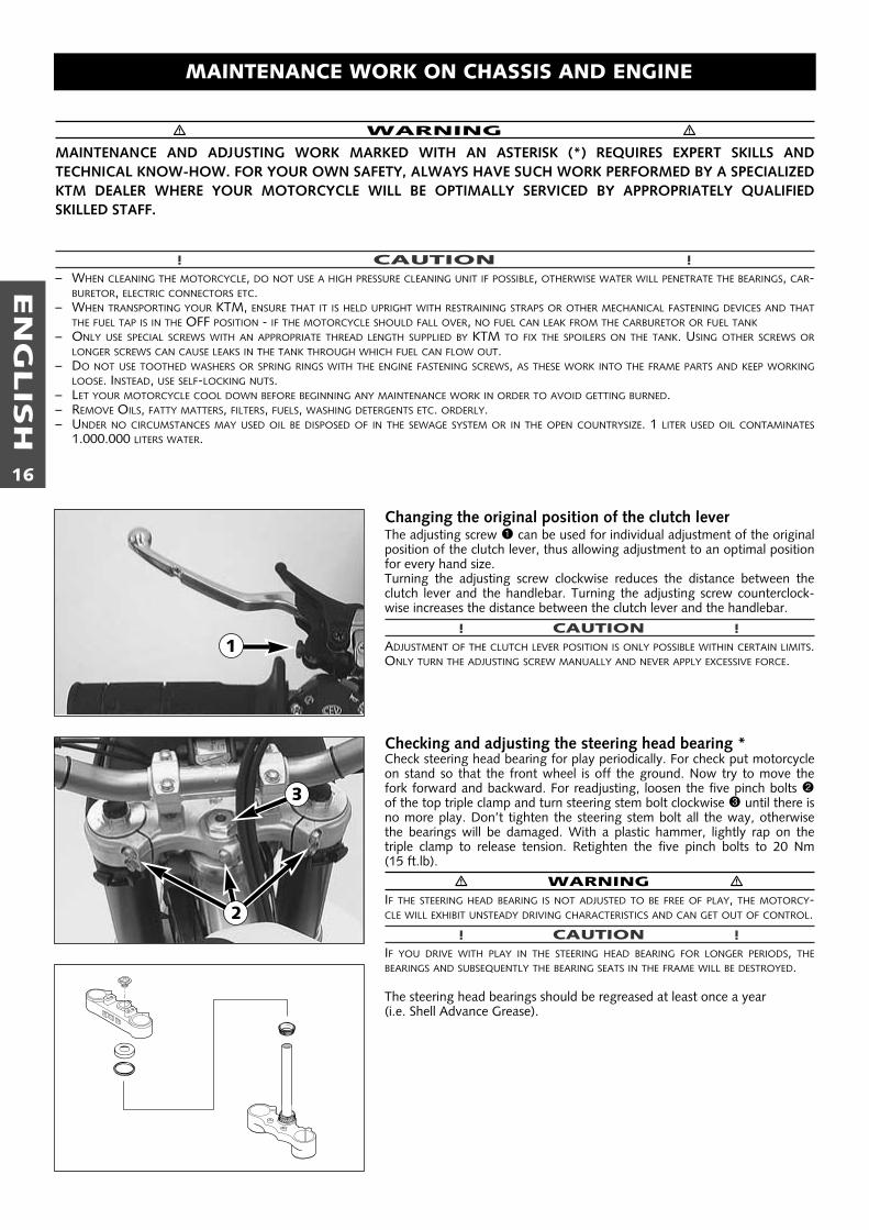
Changing the original position of the clutch leverThe adjusting screw 1 can be used for individual adjustment of the originalposition of the clutch lever, thus allowing adjustment to an optimal positionfor every hand size.Turning the adjusting screw clockwise reduces the distance between theclutch lever and the handlebar. Turning the adjusting screw counterclock-wise increases the distance between the clutch lever and the handlebar.
! CAUTION !ADJUSTMENT OF THE CLUTCH LEVER POSITION IS ONLY POSSIBLE WITHIN CERTAIN LIMITS.ONLY TURN THE ADJUSTING SCREW MANUALLY AND NEVER APPLY EXCESSIVE FORCE.
Checking and adjusting the steering head bearing *Check steering head bearing for play periodically. For check put motorcycleon stand so that the front wheel is off the ground. Now try to move thefork forward and backward. For readjusting, loosen the five pinch bolts 2of the top triple clamp and turn steering stem bolt clockwise 3 until there isno more play. Don’t tighten the steering stem bolt all the way, otherwisethe bearings will be damaged. With a plastic hammer, lightly rap on the triple clamp to release tension. Retighten the five pinch bolts to 20 Nm (15 ft.lb).
� WARNING �IF THE STEERING HEAD BEARING IS NOT ADJUSTED TO BE FREE OF PLAY, THE MOTORCY-CLE WILL EXHIBIT UNSTEADY DRIVING CHARACTERISTICS AND CAN GET OUT OF CONTROL.
! CAUTION !IF YOU DRIVE WITH PLAY IN THE STEERING HEAD BEARING FOR LONGER PERIODS, THEBEARINGS AND SUBSEQUENTLY THE BEARING SEATS IN THE FRAME WILL BE DESTROYED.
The steering head bearings should be regreased at least once a year (i.e. Shell Advance Grease).
2
3
1
EN
GLIS
H
17
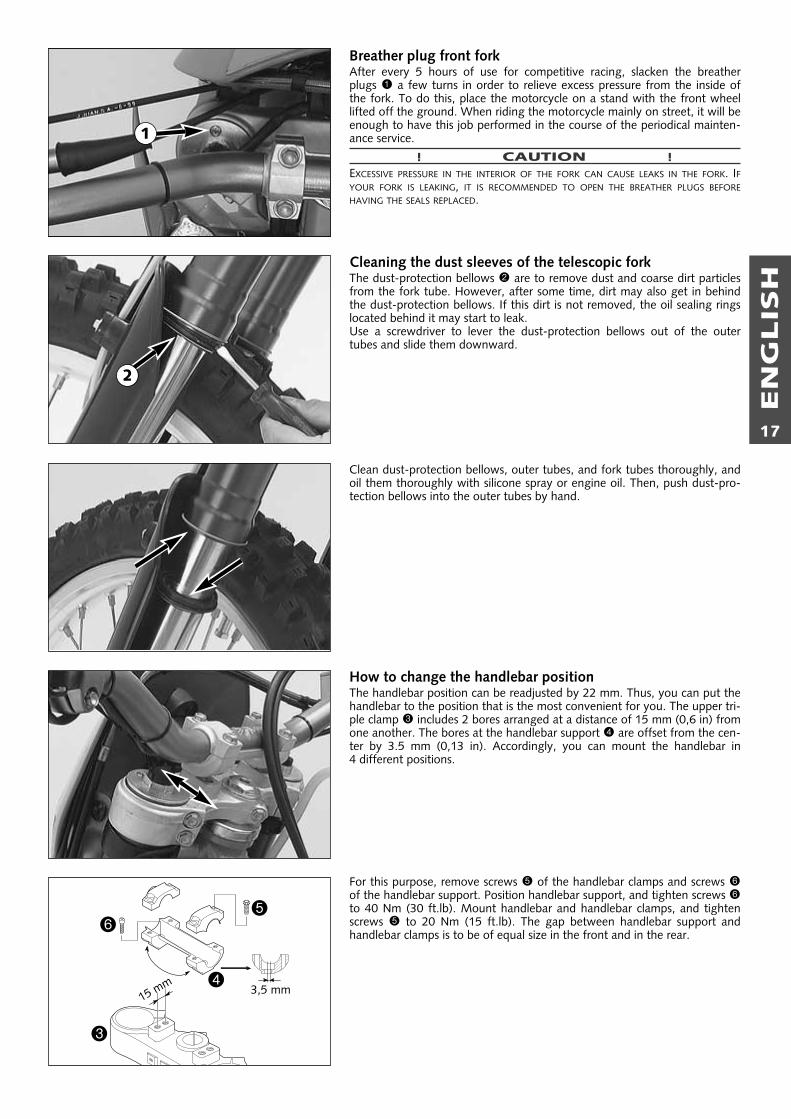
Breather plug front forkAfter every 5 hours of use for competitive racing, slacken the breather plugs 1 a few turns in order to relieve excess pressure from the inside ofthe fork. To do this, place the motorcycle on a stand with the front wheellifted off the ground. When riding the motorcycle mainly on street, it will beenough to have this job performed in the course of the periodical mainten-ance service.
! CAUTION !EXCESSIVE PRESSURE IN THE INTERIOR OF THE FORK CAN CAUSE LEAKS IN THE FORK. IFYOUR FORK IS LEAKING, IT IS RECOMMENDED TO OPEN THE BREATHER PLUGS BEFOREHAVING THE SEALS REPLACED.
Cleaning the dust sleeves of the telescopic forkThe dust-protection bellows 2 are to remove dust and coarse dirt particlesfrom the fork tube. However, after some time, dirt may also get in behindthe dust-protection bellows. If this dirt is not removed, the oil sealing ringslocated behind it may start to leak.Use a screwdriver to lever the dust-protection bellows out of the outertubes and slide them downward.
Clean dust-protection bellows, outer tubes, and fork tubes thoroughly, andoil them thoroughly with silicone spray or engine oil. Then, push dust-pro-tection bellows into the outer tubes by hand.
How to change the handlebar positionThe handlebar position can be readjusted by 22 mm. Thus, you can put thehandlebar to the position that is the most convenient for you. The upper tri-ple clamp 3 includes 2 bores arranged at a distance of 15 mm (0,6 in) fromone another. The bores at the handlebar support 4 are offset from the cen-ter by 3.5 mm (0,13 in). Accordingly, you can mount the handlebar in 4 different positions.
For this purpose, remove screws 5 of the handlebar clamps and screws 6of the handlebar support. Position handlebar support, and tighten screws 6to 40 Nm (30 ft.lb). Mount handlebar and handlebar clamps, and tightenscrews 5 to 20 Nm (15 ft.lb). The gap between handlebar support andhandlebar clamps is to be of equal size in the front and in the rear.
3
4
56
15 mm 3,5 mm
1
2
EN
GLIS
H
18
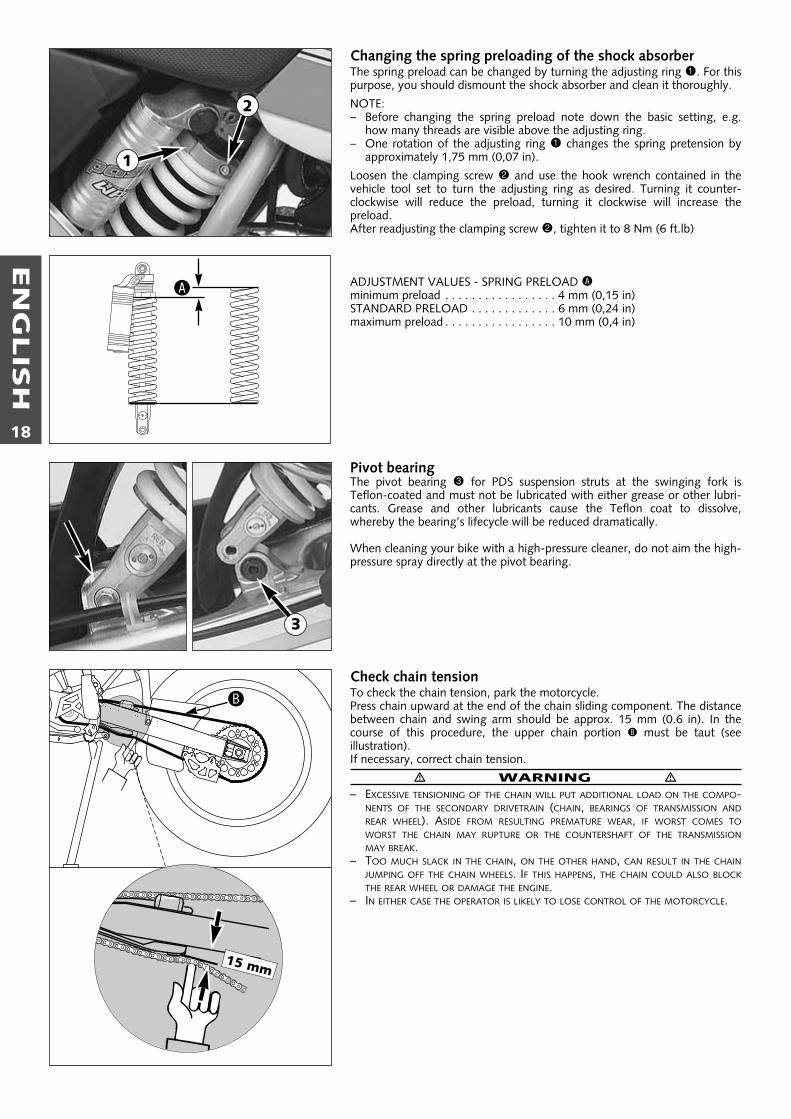
Changing the spring preloading of the shock absorberThe spring preload can be changed by turning the adjusting ring 1. For thispurpose, you should dismount the shock absorber and clean it thoroughly.
NOTE:– Before changing the spring preload note down the basic setting, e.g.
how many threads are visible above the adjusting ring.– One rotation of the adjusting ring 1 changes the spring pretension by
approximately 1,75 mm (0,07 in).
Loosen the clamping screw 2 and use the hook wrench contained in thevehicle tool set to turn the adjusting ring as desired. Turning it counter-clockwise will reduce the preload, turning it clockwise will increase the preload.After readjusting the clamping screw 2, tighten it to 8 Nm (6 ft.lb)
ADJUSTMENT VALUES - SPRING PRELOAD Aminimum preload . . . . . . . . . . . . . . . . . 4 mm (0,15 in)STANDARD PRELOAD . . . . . . . . . . . . . 6 mm (0,24 in)maximum preload . . . . . . . . . . . . . . . . . 10 mm (0,4 in)
Pivot bearingThe pivot bearing 3 for PDS suspension struts at the swinging fork isTeflon-coated and must not be lubricated with either grease or other lubri-cants. Grease and other lubricants cause the Teflon coat to dissolve, whereby the bearing’s lifecycle will be reduced dramatically.
When cleaning your bike with a high-pressure cleaner, do not aim the high-pressure spray directly at the pivot bearing.
Check chain tensionTo check the chain tension, park the motorcycle.Press chain upward at the end of the chain sliding component. The distancebetween chain and swing arm should be approx. 15 mm (0.6 in). In thecourse of this procedure, the upper chain portion B must be taut (see illustration).If necessary, correct chain tension.
� WARNING �– EXCESSIVE TENSIONING OF THE CHAIN WILL PUT ADDITIONAL LOAD ON THE COMPO-
NENTS OF THE SECONDARY DRIVETRAIN (CHAIN, BEARINGS OF TRANSMISSION ANDREAR WHEEL). ASIDE FROM RESULTING PREMATURE WEAR, IF WORST COMES TOWORST THE CHAIN MAY RUPTURE OR THE COUNTERSHAFT OF THE TRANSMISSIONMAY BREAK.
– TOO MUCH SLACK IN THE CHAIN, ON THE OTHER HAND, CAN RESULT IN THE CHAINJUMPING OFF THE CHAIN WHEELS. IF THIS HAPPENS, THE CHAIN COULD ALSO BLOCKTHE REAR WHEEL OR DAMAGE THE ENGINE.
– IN EITHER CASE THE OPERATOR IS LIKELY TO LOSE CONTROL OF THE MOTORCYCLE.
15 mm
B
2
A
1
3
EN
GLIS
H
19
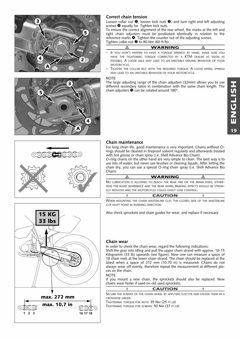
Correct chain tensionLoosen collar nut 2, loosen lock nuts 3, and turn right and left adjustingscrews 4 equally far. Tighten lock nuts.To ensure the correct alignment of the rear wheel, the marks at the left andright chain adjusters must be positioned identically in relation to the reference marks A. Tighten the counter nut of the adjusting screws.Tighten collar nut 2 to 80 Nm (60 ft.lb).
� WARNING �– IF YOU DON’T HAPPEN TO HAVE A TORQUE WRENCH AT HAND, MAKE SURE YOU
HAVE THE TIGHTENING TORQUE CORRECTED BY A KTM DEALER AS SOON ASPOSSIBLE. A LOOSE AXLE MAY LEAD TO AN UNSTABLE DRIVING BEHAVIOR OF YOURMOTORCYCLE.
– TIGHTEN THE COLLAR NUT WITH THE REQUIRED TORQUE. A LOOSE WHEEL SPINDLEMAY LEAD TO AN UNSTABLE BEHAVIOR OF YOUR MOTORCYCLE.
NOTE:The large adjusting range of the chain adjusters (32mm) allows you to usedifferent secondary ratios in combination with the same chain length. Thechain adjusters 5 can be rotated around 180°.
Chain maintenanceFor long chain life, good maintenance is very important. Chains without O-rings should be cleaned in fireproof solvent regularly and afterwards treatedwith hot grease or chain spray (i.e. Shell Advance Bio Chain).O-ring chains on the other hand are very simple to clean. The best way is touse lots of water, but never use brushes or cleaning liquids. After letting thechain dry, you can use a special O-ring chain spray (i.e. Shell Advance BioChain).
� WARNING �NO LUBRICATION IS ALLOWED TO REACH THE REAR TIRE OR THE BRAKE DISKS, EITHER-WISE THE ROAD ADHERENCE AND THE REAR WHEEL BRAKING EFFECTS WOULD BE STRON-GLY REDUCED AND THE MOTORCYCLE COULD EASILY LOSE CONTROL.
! CAUTION !WHEN MOUNTING THE CHAIN MASTERLINK CLIP, THE CLOSED SIDE OF THE MASTERLINKCLIP MUST POINT IN RUNNING DIRECTION.
Also check sprockets and chain guides for wear, and replace if necessary.
Chain wearIn order to check the chain wear, regard the following indications:Shift the gear into idling and pull the upper chain strand with approx. 10-15Kilogramm (33 lb) upwards (see figure). Now one can measure a space of18 chain reels at the lower chain strand. The chain should be replaced at thelatest when a space of 272 mm (10.70 in) is measured. Chains do notalways wear off evenly, therefore repeat the measurement at different pla-ces on the chain.NOTE:If you mount a new chain, the sprockets should also be replaced. Newchains wear faster if used on old used sprockets.
! CAUTION !SECURE THE SCREWS OF THE CHAIN WHEEL BY APPLYING LOCTITE AND FASTEN THEM IN ACROSSWISE ORDER.TIGHTENING TORQUE FOR NUTS: 35 NM (25 FT.LB)TIGHTENING TORQUE FOR SCREWS: 50 NM (37 FT.LB)
15 KG33 lbs
max. 272 mm
1 2 3 16 17 18
�
2
3
4
5
3
4
A
5
A
max. 10,7 in

EN
GLIS
H
20
General information about KTM disc brakesBRAKE CALIPERS:The brake calipers of this series use a „floating” mount. This means that thebrake calipers are not solidly attached to the caliper support, which enablesthem to „float” for maximum braking contact.
BRAKE PADS:The brake pads are fitted with TOSHIBA TT 2701 sintered lining at the frontand TOSHIBA H 38 sintered lining at the back. These linings provide anoptimal combination of dosing, brake performance and lifecycle. The liningtype is stated on the back of the brake pad and also recorded in the homo-logation papers. Other brake pads are available for competition sports.FRONT: TOSHIBA H 38 (SINTERED) – harder to dose, good brake per-
formance, long life, for wet slippery terrain.FERODO ID 450 (ORGANIC) – easy to dose, good brake per-formance, short life, for dry terrain, low price
REAR: FERODO ID 450 (ORGANIC) – easy to dose, good brake per-formance, short life, for dry terrain, low priceFERRIT 222 (ORGANIC) – can be dosed better, short life cycle, fordry terrain.
BRAKE DISCS:Due to wear, the thickness of the brake disc in the area of the contact face 1 of the brake pads decreases. At their thinnest point A, the brakediscs must not be more than 0.40 mm (0,016 in) thinner than the pad'snominal thickness. Measure the nominal thickness in a location B outsidethe contact face. Check wear in several locations.
� WARNING �– BRAKE DISCS SUFFERING FROM WEAR GREATER THAN 0,4 MM (0,016 IN) CONSTI-
TUTE A SAFETY RISK. HAVE THE BRAKE DISCS REPLACED IMMEDIATELY AS SOON ASTHEY REACH THE WEAR LIMIT.
– HAVE ANY REPAIRS ON THE BRAKE SYSTEM BE PERFORMED BY A KTM DEALER
BRAKE FLUID RESERVOIRS:The brake fluid reservoirs on front and rear wheel brakes have been desi-gned in such a way that even if the brake pads are worn it is not necessaryto top up the brake fluid. If the brake fluid level drops below the minimumlevel either the brake system has a leak or the brake pads are completelyworn.In this case, consult an authorized KTM dealer immediately.
BRAKE FLUID:KTM fills the brake systems with SHELL ADVANCE BRAKE DOT 5.1 brakefluid, one of the best brake fluids that is currently available. We recommendthat you continue to use it. DOT 5.1 brake fluid is based on glycol etherand of an amber color. If you do not have any DOT 5.1 for refilling, youmay use DOT 4 brake fluid. However, you should replace it as soon as possible by DOT 5.1.Never use brake fluid DOT 5. The color of this silicon oil-based product ispurple red. The gaskets and brake hoses of KTM motorcycles are not designed for DOT 5 brake fluid!
� WARNING �HAVE THE BRAKE FLUID CHANGED AT LEAST ONCE ANNUALLY. IF YOU WASH YOURMOTORCYCLE OFTEN, THE BRAKE FLUID SHOULD BE CHANGED EVEN MORE FREQUENTLY.BRAKE FLUID TENDS TO ABSORB WATER. THEREFORE, VAPOR POCKETS MAY FORM IN"OLD" BRAKE FLUIDS EVEN AT LOW TEMPERATURES, CAUSING THE BRAKE SYSTEM TOFAIL.
Adjusting of free travel at the hand brake leverFree travel at the hand brake lever may be readjusted by using adjustmentscrew 2. In this way, the position of the point of pressure (i.e., the resi-stance you feel on the hand brake lever when the brake pads are pressedagainst the brake disc) can be adjusted for any hand size.
! CAUTION !AT THE HAND BRAKE LEVER, FREE TRAVEL MUST AT LEAST BE 3 MM (0.1 IN). ONLYTHEN MAY THE PISTON IN THE HAND BRAKE CYLINDER BE MOVED (TO BE RECOGNIZED BYTHE GREATER RESISTANCE OF THE HAND BRAKE LEVER). IF THIS FREE TRAVEL IS NOT PRO-VIDED, PRESSURE WILL BUILD UP IN THE BRAKING SYSTEM, AND THE FRONT-WHEEL BRAKEMAY FAIL DUE TO OVERHEATING.
DOT5.1
DOT5
� ✕
min. 3 mm
A
B
1
2
EN
GLIS
H
21
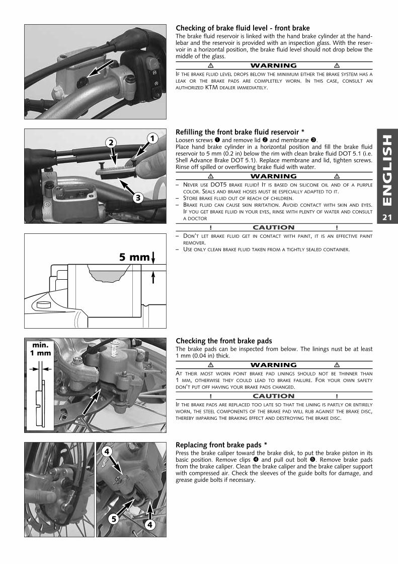
Checking of brake fluid level - front brakeThe brake fluid reservoir is linked with the hand brake cylinder at the hand-lebar and the reservoir is provided with an inspection glass. With the reser-voir in a horizontal position, the brake fluid level should not drop below themiddle of the glass.
� WARNING �IF THE BRAKE FLUID LEVEL DROPS BELOW THE MINIMUM EITHER THE BRAKE SYSTEM HAS ALEAK OR THE BRAKE PADS ARE COMPLETELY WORN. IN THIS CASE, CONSULT ANAUTHORIZED KTM DEALER IMMEDIATELY.
Refilling the front brake fluid reservoir *Loosen screws 1 and remove lid 2 and membrane 3. Place hand brake cylinder in a horizontal position and fill the brake fluidreservoir to 5 mm (0.2 in) below the rim with clean brake fluid DOT 5.1 (i.e.Shell Advance Brake DOT 5.1). Replace membrane and lid, tighten screws.Rinse off spilled or overflowing brake fluid with water.
� WARNING �– NEVER USE DOT5 BRAKE FLUID! IT IS BASED ON SILICONE OIL AND OF A PURPLE
COLOR. SEALS AND BRAKE HOSES MUST BE ESPECIALLY ADAPTED TO IT.– STORE BRAKE FLUID OUT OF REACH OF CHILDREN.– BRAKE FLUID CAN CAUSE SKIN IRRITATION. AVOID CONTACT WITH SKIN AND EYES.
IF YOU GET BRAKE FLUID IN YOUR EYES, RINSE WITH PLENTY OF WATER AND CONSULTA DOCTOR
! CAUTION !– DON’T LET BRAKE FLUID GET IN CONTACT WITH PAINT, IT IS AN EFFECTIVE PAINT
REMOVER.– USE ONLY CLEAN BRAKE FLUID TAKEN FROM A TIGHTLY SEALED CONTAINER.
Checking the front brake padsThe brake pads can be inspected from below. The linings nust be at least 1 mm (0.04 in) thick.
� WARNING �AT THEIR MOST WORN POINT BRAKE PAD LININGS SHOULD NOT BE THINNER THAN1 MM, OTHERWISE THEY COULD LEAD TO BRAKE FAILURE. FOR YOUR OWN SAFETYDON’T PUT OFF HAVING YOUR BRAKE PADS CHANGED.
! CAUTION !IF THE BRAKE PADS ARE REPLACED TOO LATE SO THAT THE LINING IS PARTLY OR ENTIRELYWORN, THE STEEL COMPONENTS OF THE BRAKE PAD WILL RUB AGAINST THE BRAKE DISC,THEREBY IMPARING THE BRAKING EFFECT AND DESTROYING THE BRAKE DISC.
Replacing front brake pads *Press the brake caliper toward the brake disk, to put the brake piston in itsbasic position. Remove clips 4 and pull out bolt 5. Remove brake padsfrom the brake caliper. Clean the brake caliper and the brake caliper supportwith compressed air. Check the sleeves of the guide bolts for damage, andgrease guide bolts if necessary.
min.1 mm
5 mm
12
3
4
45

EN
GLIS
H
22
Mount the right brake pad and fix it with the bolt. Mount the left brake padand insert the bolt until it stops. Mount the clips.When mounting the brake pads, be sure to check for correct fit of the sliding metal-sheet 6 in the caliper support and of the leaf spring 7.
� WARNING �– IT IS VERY IMPORTANT TO KEEP THE BRAKE DISK FREE FROM OIL AND FATTY MATTERS.
OTHERWISE, THE BRAKING EFFECT WOULD BE STRONGLY REDUCED.– AFTER ASSEMBLY, CHECK IF CIRCLIPS HAVE BEEN FITTED CORRECTLY.– HAVING PERFORMED ANY WORK ON THE BRAKING SYSTEM, ONE MUST ALWAYS
ACTUATE THE HAND BRAKE LEVER OR FOOT BRAKE LEVER, RESPECTIVELY SO AS TOENSURE THAT THE BRAKE PADS WILL LIE AGAINST THE BRAKE DISK AND THE PRESSUREPOINT IS ESTABLISHED.
Changing the basic position of the foot brake pedal *The basic position of the foot brake pedal can be altered by turning the stopscrew 1. The free play at the foot brake pedal must then be adjusted bymeans of the piston rod 2.Measured on the outside, the foot brake pedal must have 3-5 mm(0.12–0.20 in) of free play, before the piston rod can move the piston in thebrake cylinder (to be recognised from the resistance on the foot brakepedal).
! CAUTION !IF THIS FREE PLAY IS NOT PRESENT, THEN PRESSURE CAN BUILD UP IN THE BRAKE SYSTEMWHEN DRIVING, CAUSING THE REAR WHEEL TO BRAKE.THE BRAKING SYSTEM OVERHEATSAND MAY EVEN FAIL COMPLETELY IN EXTREME CASES.
Checking rear brake fluid levelThe reservoir for the rear disc brake is disposed on the engine in the vicinityof the oil filters. The brake fluid level must not drop below the „MlN” mar-king when the vehicle is in an upright position.
� WARNING �IF THE BRAKE FLUID LEVEL DROPS BELOW THE MINIMUM EITHER THE BRAKE SYSTEM HAS ALEAK OR THE BRAKE PADS ARE COMPLETELY WORN. IN THIS CASE, CONSULT ANAUTHORIZED KTM DEALER IMMEDIATELY.
Refilling the rear brake fluid reservoir *When the brake fluid level has dropped to the MIN mark, you need to refillthe brake fluid reservoir. This is done by first unscrewing the cap 3 and rubber bellows 4. Addbrake fluid DOT 5.1 (Shell Advance Brake DOT 5.1) until it reaches theMAX mark, then screw rubber bellows and cap back on. Rinse off spilled oroverflowing brake fluid with water.
� WARNING �– NEVER USE DOT5 BRAKE FLUID! IT IS BASED ON SILICONE OIL AND OF A PURPLE
COLOR. SEALS AND BRAKE HOSES MUST BE ESPECIALLY ADAPTED TO IT.– STORE BRAKE FLUID OUT OF REACH OF CHILDREN.– BRAKE FLUID CAN CAUSE SKIN IRRITATION. AVOID CONTACT WITH SKIN AND EYES.
IF YOU GET BRAKE FLUID IN YOUR EYES, RINSE WITH PLENTY OF WATER AND CONSULTA DOCTOR.
! CAUTION !– DON’T LET BRAKE FLUID GET IN CONTACT WITH PAINT, IT IS AN EFFECTIVE PAINT
REMOVER.– USE ONLY CLEAN BRAKE FLUID TAKEN FROM A TIGHTLY SEALED CONTAINER.
6 7
4
5
3-5mm
3
4
5
1
2
3

EN
GLIS
H
23
Checking the rear brake padsThe brake pads can be inspected from the rear. The thickness of the liningsmay not be less than 1 mm (0.04 in).
� WARNING �AT THEIR MOST WORN POINT BRAKE PAD LININGS SHOULD NOT BE THINNER THAN1 MM, OTHERWISE THEY COULD LEAD TO BRAKE FAILURE. FOR YOUR OWN SAFETYDON’T PUT OFF HAVING YOUR BRAKE PADS CHANGED.
! CAUTION !IF THE BRAKE PADS ARE REPLACED TOO LATE SO THAT THE LINING IS PARTLY OR ENTIRELYWORN, THE STEEL COMPONENTS OF THE BRAKE PAD WILL RUB AGAINST THE BRAKE DISC,THEREBY IMPARING THE BRAKING EFFECT AND DESTROYING THE BRAKE DISC.
Replacing the rear brake pads *Push the brake caliper 1 toward the chain wheel in order to move thebrake piston into its basic position. Remove clips 2, pull out the bolt 3,and remove the brake pads. Thoroughly clean the brake caliper with com-pressed air and check the sleeves of the guide bolts for damage.
Insert the left brake pad into the brake caliper and secure it with the bolt.Insert the right brake pad and push the bolt 3 into the brake caliper up tothe stop. Reattach clips 2.
� WARNING �– IT IS VERY IMPORTANT TO KEEP THE BRAKE DISK FREE FROM OIL AND FATTY MATTERS.
OTHERWISE, THE BRAKING EFFECT WOULD BE STRONGLY REDUCED.– AFTER ASSEMBLY, CHECK IF CLIPS HAVE BEEN FITTED CORRECTLY.– HAVING PERFORMED ANY WORK ON THE BRAKING SYSTEM, ONE MUST ALWAYS
ACTUATE THE HAND BRAKE LEVER OR FOOT BRAKE LEVER, RESPECTIVELY SO AS TOENSURE THAT THE BRAKE PADS WILL LIE AGAINST THE BRAKE DISK AND THE PRESSUREPOINT IS ESTABLISHED.
Dismounting and mounting the front wheelTo remove the front wheel, jack the motorcycle up on its frame so that thefront wheel no longer touches the ground.Loosen the 2 clamping screws 5 on the left side of the fork fists.Loosen and remove the collar nut 4., loosen the clamping screews 6 onthe right side 6 of the fork fistHold the front wheel, pull out the wheel spindle 7.NOTE: The wheel spindle can be easily removed if you slightly revolve itwith a ring span-ner (SW 21 mm) or a hexagon socket screw key (6 mm).Remove front wheel carefully from the fork and take the speedometer drive8 off the hub.NOTE: Models with a digital speedometer have a distance bushing insteadof the speed-ometer drive.
! CAUTION !– DO NOT OPERATE THE HAND BRAKE WHEN THE FRONT WHEEL HAS BEEN
DISMOUNTED.– MAKE SURE THE BRAKE DISC IS ALWAYS ON TOP WHEN YOU LAY DOWN THE WHEEL,
OTHERWISE THE BRAKE DISC CAN BE DAMAGED.
Prior to mounting the front wheel, clean and grease sealing ring 9 and running surface bk at the speedometer drive. Lift front wheel into fork, and insert speedometer drive or distance sleeveinto hub. Make sure that the driving tabs bl engage with the slot of thedrive.Position front wheel and speedometer drive or distance sleeve and mountwheel spindle.
min.1 mm
2
45
1
3
6
7
8
8
9
10
11
EN
GLIS
H
24
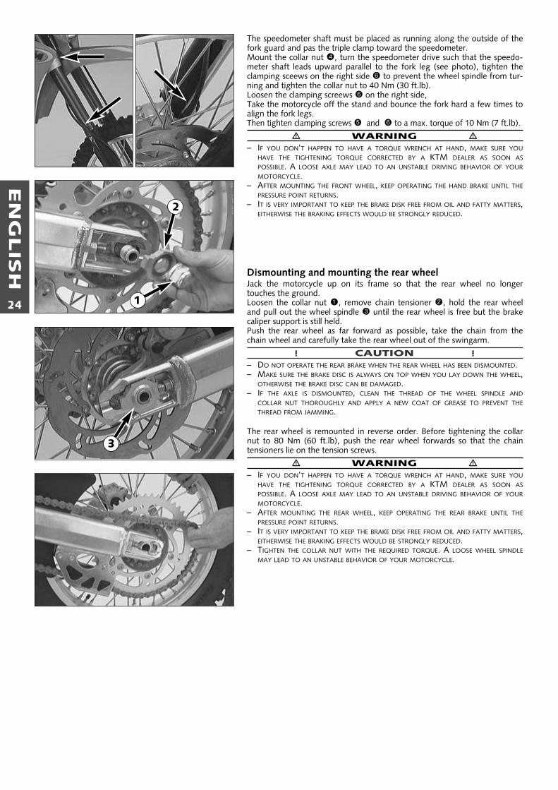
The speedometer shaft must be placed as running along the outside of thefork guard and pas the triple clamp toward the speedometer.Mount the collar nut 4, turn the speedometer drive such that the speedo-meter shaft leads upward parallel to the fork leg (see photo), tighten theclamping sceews on the right side 6 to prevent the wheel spindle from tur-ning and tighten the collar nut to 40 Nm (30 ft.lb).Loosen the clamping screews 6 on the right side,Take the motorcycle off the stand and bounce the fork hard a few times toalign the fork legs.Then tighten clamping screws 5 and 6 to a max. torque of 10 Nm (7 ft.lb).
� WARNING �– IF YOU DON’T HAPPEN TO HAVE A TORQUE WRENCH AT HAND, MAKE SURE YOU
HAVE THE TIGHTENING TORQUE CORRECTED BY A KTM DEALER AS SOON ASPOSSIBLE. A LOOSE AXLE MAY LEAD TO AN UNSTABLE DRIVING BEHAVIOR OF YOURMOTORCYCLE.
– AFTER MOUNTING THE FRONT WHEEL, KEEP OPERATING THE HAND BRAKE UNTIL THEPRESSURE POINT RETURNS.
– IT IS VERY IMPORTANT TO KEEP THE BRAKE DISK FREE FROM OIL AND FATTY MATTERS,EITHERWISE THE BRAKING EFFECTS WOULD BE STRONGLY REDUCED.
Dismounting and mounting the rear wheelJack the motorcycle up on its frame so that the rear wheel no longer touches the ground.Loosen the collar nut 1, remove chain tensioner 2, hold the rear wheeland pull out the wheel spindle 3 until the rear wheel is free but the brakecaliper support is still held.Push the rear wheel as far forward as possible, take the chain from thechain wheel and carefully take the rear wheel out of the swingarm.
! CAUTION !– DO NOT OPERATE THE REAR BRAKE WHEN THE REAR WHEEL HAS BEEN DISMOUNTED.– MAKE SURE THE BRAKE DISC IS ALWAYS ON TOP WHEN YOU LAY DOWN THE WHEEL,
OTHERWISE THE BRAKE DISC CAN BE DAMAGED.– IF THE AXLE IS DISMOUNTED, CLEAN THE THREAD OF THE WHEEL SPINDLE AND
COLLAR NUT THOROUGHLY AND APPLY A NEW COAT OF GREASE TO PREVENT THETHREAD FROM JAMMING.
The rear wheel is remounted in reverse order. Before tightening the collarnut to 80 Nm (60 ft.lb), push the rear wheel forwards so that the chain tensioners lie on the tension screws.
� WARNING �– IF YOU DON’T HAPPEN TO HAVE A TORQUE WRENCH AT HAND, MAKE SURE YOU
HAVE THE TIGHTENING TORQUE CORRECTED BY A KTM DEALER AS SOON ASPOSSIBLE. A LOOSE AXLE MAY LEAD TO AN UNSTABLE DRIVING BEHAVIOR OF YOURMOTORCYCLE.
– AFTER MOUNTING THE REAR WHEEL, KEEP OPERATING THE REAR BRAKE UNTIL THEPRESSURE POINT RETURNS.
– IT IS VERY IMPORTANT TO KEEP THE BRAKE DISK FREE FROM OIL AND FATTY MATTERS,EITHERWISE THE BRAKING EFFECTS WOULD BE STRONGLY REDUCED.
– TIGHTEN THE COLLAR NUT WITH THE REQUIRED TORQUE. A LOOSE WHEEL SPINDLEMAY LEAD TO AN UNSTABLE BEHAVIOR OF YOUR MOTORCYCLE.
1
2
3
EN
GLIS
H
25
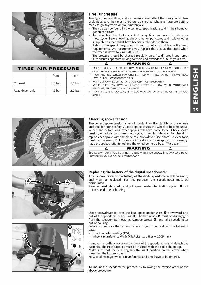
Tires, air pressureTire type, tire condition, and air pressure level affect the way your motor-cycle rides, and they must therefore be checked whenever you are gettingready to go anywhere on your motorcycle.– Tire size can be found in the technical specifications and in their homolo-
gation certificate– Tire condition has to be checked every time you want to ride your
motorcycle. Before leaving, check tires for punctures and nails or othersharp objects that might have become embedded in them.Refer to the specific regulations in your country for minimum tire treadrequirements. We recommend you replace the tires at the latest whenthe tread is down to 2 mm (0.08 in).
– Tire pressure should be checked regularly on a “cold” tire. Proper pres-sure ensures optimum driving comfort and extends the life of your tires.
� WARNING �– DO NOT MOUNT TIRES WHICH HAVE NOT BEEN APPROVED BY KTM. OTHER TIRES
COULD HAVE ADVERSE EFFECTS ON THE WAY YOUR MOTORCYCLE BEHAVES.– FRONT AND REAR WHEELS MAY ONLY BE FITTED WITH TIRES HAVING THE SAME TREAD
LAYOUT. USE HOMOLOGATED TIRES.– FOR YOUR OWN SAFETY REPLACE DAMAGED TIRES IMMEDIATELY.– WORN TIRES CAN HAVE A NEGATIVE EFFECT ON HOW YOUR MOTORCYCLE
PERFORMS, ESPECIALLY ON WET SURFACES.– IF AIR PRESSURE IS TOO LOW, ABNORMAL WEAR AND OVERHEATING OF THE TIRE CAN
RESULT.
Checking spoke tensionThe correct spoke tension is very important for the stability of the wheelsand thus for riding safety. A loose spoke causes the wheel to become unba-lanced and before long other spokes will have come loose. Check spoketension, especially on a new motorcycle, in regular intervals. For checking,tap on each spoke with the blade of a screwdriver (see photo). A clear tonemust be the result. Dull tones are indicators of loose spokes. If necessary,have the spokes retightened and the wheel centered by a KTM dealer.
� WARNING �SPOKES CAN TEAR IF YOU CONTINUE TO RIDE WITH THEM LOOSE. THIS MAY LEAD TO ANUNSTABLE HANDLING OF YOUR MOTORCYCLE.
Replacing the battery of the digital speedometerAfter approx. 2 years, the battery of the digital speedometer will be emptyand must be replaced. For this purpose, the speedometer must be dismounted.Remove headlight mask, and pull speedometer illumination system 1 outof the speedometer housing.
Use a screwdriver to lever the blue speedometer glass 2 downward andout of the speedometer housing 3. The two noses A must be disengagedfrom the speedometer housing. Remove screws 4, and take speedometerout of housing.Before you remove the battery, do not forget to write down the followingdata:– total kilometer reading (DST)– wheel circumference (WS) (KTM standard tires = 2205 mm)
Remove the battery cover on the back of the speedometer and detach thebatteries. The new batteries must be inserted with the plus pole on top.Make sure that the seal ring has the right position on the cover whenmounting the battery cover.Now total mileage, wheel circumference and time have to be entered.
To mount the speedometer, proceed by following the reverse order of theabove procedure.
front rear
Off road 1,0 bar 1,0 bar
Road driver only 1,5 bar 2,0 bar
TIRES-AIR PRESSURE
1
3
2
4
A A
2
4

EN
GLIS
H
26
TOTAL MILEAGE „DST“
TIME „CLK“
AFTER CHANGING BATTERY
1 sec
5 sec
1 sec
1. use the right button toselect the position to bechanged
1. make sure the time isindicated and push thebutton on the backapprox. 5 seconds (timestarts blinking)
2. push the left button until the rightfigure is showed in the display
3. by pushing the right but-ton you jump to the nextfigure
4. repeat nos. 2 + 3 until correct time is indicated
5. push the button onthe back approx. 1second to terminatethe setting procedure
2. push the left button untilthe right figure is showedin the display
3. by pushing the right but-ton you jump to the nextfigure
4. repeat nos. 2 + 3 until the previouslynoted total mileage is indicated
5. push the button on theback with a sharp objectapprox. 1 second to termi-nate the setting procedure(the value is thus stored)

EN
GLIS
H
27
Check/set distance of the magnetic sensorThe distance between magnet 2 and sensor 1 must be 2-4 mm (0,08-0,16 in), otherwise malfunctions on the speedometer might occur.
This distance can be corrected by screwing in or off the sensor 1.
WHEEL CIRCUMFERENCE „WS“
1. make sure that the indication"TRP" is active and push the but-ton on the back approx. 5 seconds("WS" appears)
2. use the right button to select the positionto be changed
3. push the left button until the right figureis showed in the display
4. repeat nos. 2 + 3 untilcorrect wheel circumfe-rence is indicated
5. push the button onthe back for approx. 1second to terminatethe setting procedure
5 sec
1 sec
mm x 3,14
km/h:WS = mm x 3,14
mp/h:WS = (mm x 3,14) : 1,61
1
1
2
Wheel circumference with standard tires = 2205 mm
EN
GLIS
H
28
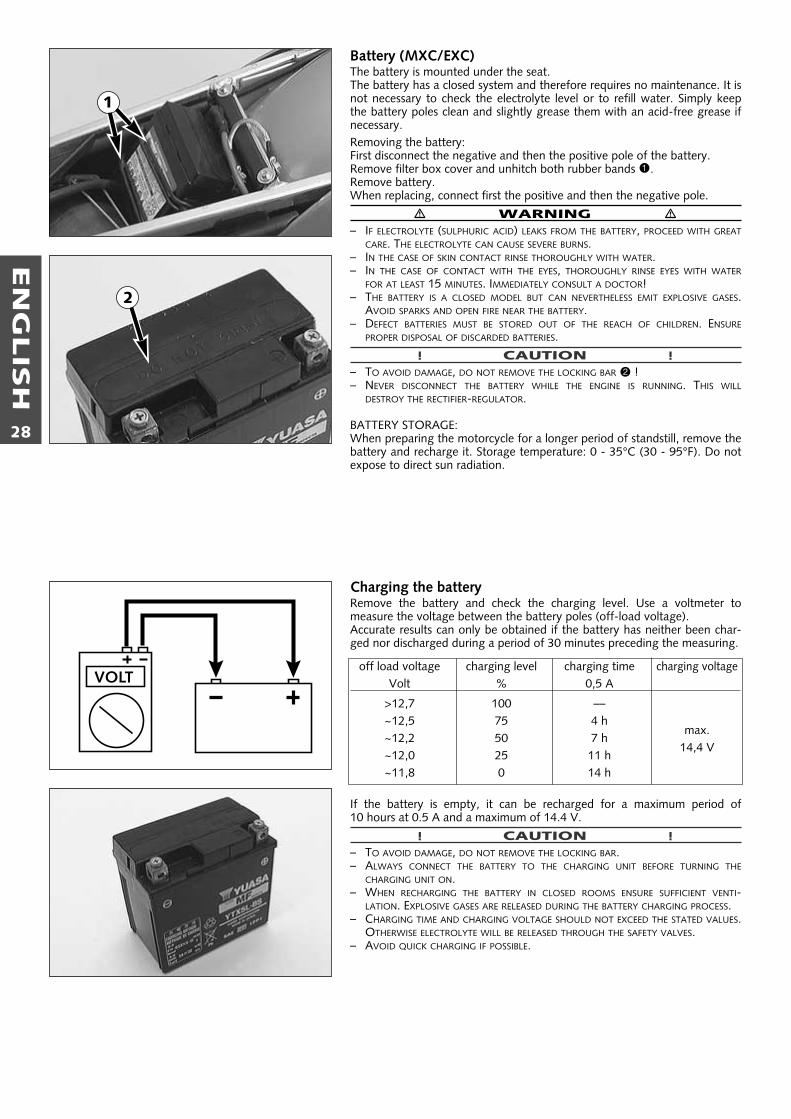
Battery (MXC/EXC)The battery is mounted under the seat.The battery has a closed system and therefore requires no maintenance. It isnot necessary to check the electrolyte level or to refill water. Simply keepthe battery poles clean and slightly grease them with an acid-free grease ifnecessary.Removing the battery:First disconnect the negative and then the positive pole of the battery.Remove filter box cover and unhitch both rubber bands 1.Remove battery.When replacing, connect first the positive and then the negative pole.
� WARNING �– IF ELECTROLYTE (SULPHURIC ACID) LEAKS FROM THE BATTERY, PROCEED WITH GREAT
CARE. THE ELECTROLYTE CAN CAUSE SEVERE BURNS.– IN THE CASE OF SKIN CONTACT RINSE THOROUGHLY WITH WATER.– IN THE CASE OF CONTACT WITH THE EYES, THOROUGHLY RINSE EYES WITH WATER
FOR AT LEAST 15 MINUTES. IMMEDIATELY CONSULT A DOCTOR!– THE BATTERY IS A CLOSED MODEL BUT CAN NEVERTHELESS EMIT EXPLOSIVE GASES.
AVOID SPARKS AND OPEN FIRE NEAR THE BATTERY.– DEFECT BATTERIES MUST BE STORED OUT OF THE REACH OF CHILDREN. ENSURE
PROPER DISPOSAL OF DISCARDED BATTERIES.
! CAUTION !– TO AVOID DAMAGE, DO NOT REMOVE THE LOCKING BAR 2 !– NEVER DISCONNECT THE BATTERY WHILE THE ENGINE IS RUNNING. THIS WILL
DESTROY THE RECTIFIER-REGULATOR.
BATTERY STORAGE:When preparing the motorcycle for a longer period of standstill, remove thebattery and recharge it. Storage temperature: 0 - 35°C (30 - 95°F). Do notexpose to direct sun radiation.
Charging the batteryRemove the battery and check the charging level. Use a voltmeter to measure the voltage between the battery poles (off-load voltage).Accurate results can only be obtained if the battery has neither been char-ged nor discharged during a period of 30 minutes preceding the measuring.
If the battery is empty, it can be recharged for a maximum period of 10 hours at 0.5 A and a maximum of 14.4 V.
! CAUTION !– TO AVOID DAMAGE, DO NOT REMOVE THE LOCKING BAR.– ALWAYS CONNECT THE BATTERY TO THE CHARGING UNIT BEFORE TURNING THE
CHARGING UNIT ON.– WHEN RECHARGING THE BATTERY IN CLOSED ROOMS ENSURE SUFFICIENT VENTI-
LATION. EXPLOSIVE GASES ARE RELEASED DURING THE BATTERY CHARGING PROCESS.– CHARGING TIME AND CHARGING VOLTAGE SHOULD NOT EXCEED THE STATED VALUES.
OTHERWISE ELECTROLYTE WILL BE RELEASED THROUGH THE SAFETY VALVES.– AVOID QUICK CHARGING IF POSSIBLE.
off load voltage charging level charging time charging voltageVolt % 0,5 A
>12,7 100 ––~12,5 75 4 h
max.~12,2 50 7 h
14,4 V~12,0 25 11 h~11,8 0 14 h
VOLT
1
2
EN
GLIS
H
29
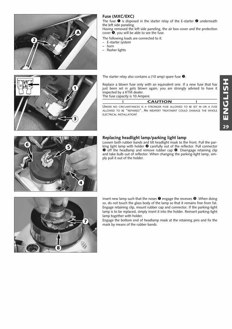
Fuse (MXC/EXC)The fuse 1 is disposed in the starter relay of the E-starter 2 underneaththe left side paneling.Having removed the left side paneling, the air box cover and the protectioncover A, you will be able to see the fuse.
The following loads are connected to it:– E-starter system– horn– flasher lights
The starter relay also contains a (10 amp) spare fuse 3.
Replace a blown fuse only with an equivalent one. If a new fuse that hasjust been set in gets blown again, you are strongly advised to have it inspected by a KTM dealer.The fuse capacity is 10 Ampere.
! CAUTION !UNDER NO CIRCUMSTANCES IS A STRONGER FUSE ALLOWED TO BE SET IN OR A FUSEALLOWED TO BE “REPAIRED”. AN INEXPERT TREATMENT COULD DAMAGE THE WHOLEELECTRICAL INSTALLATION!
Replacing headlight lamp/parking light lampLoosen both rubber bands and tilt headlight mask to the front. Pull the par-king light lamp with holder 4 carefully out of the reflector. Pull connector5 off the headlamp and remove rubber cap 6. Disengage retaining clipand take bulb out of reflector. When changing the parking-light lamp, sim-ply pull it out of the holder.
Insert new lamp such that the noses 7 engage the recesses 8 .When doingso, do not touch the glass body of the lamp so that it remains free from fat.Engage retaining clip, mount rubber cap and connector. If the parking-lightlamp is to be replaced, simply insert it into the holder. Reinsert parking-lightlamp together with holder.Engage the bottom end of headlamp mask at the retaining pins and fix themask by means of the rubber bands.
1
2
3
A
7
56
4
8
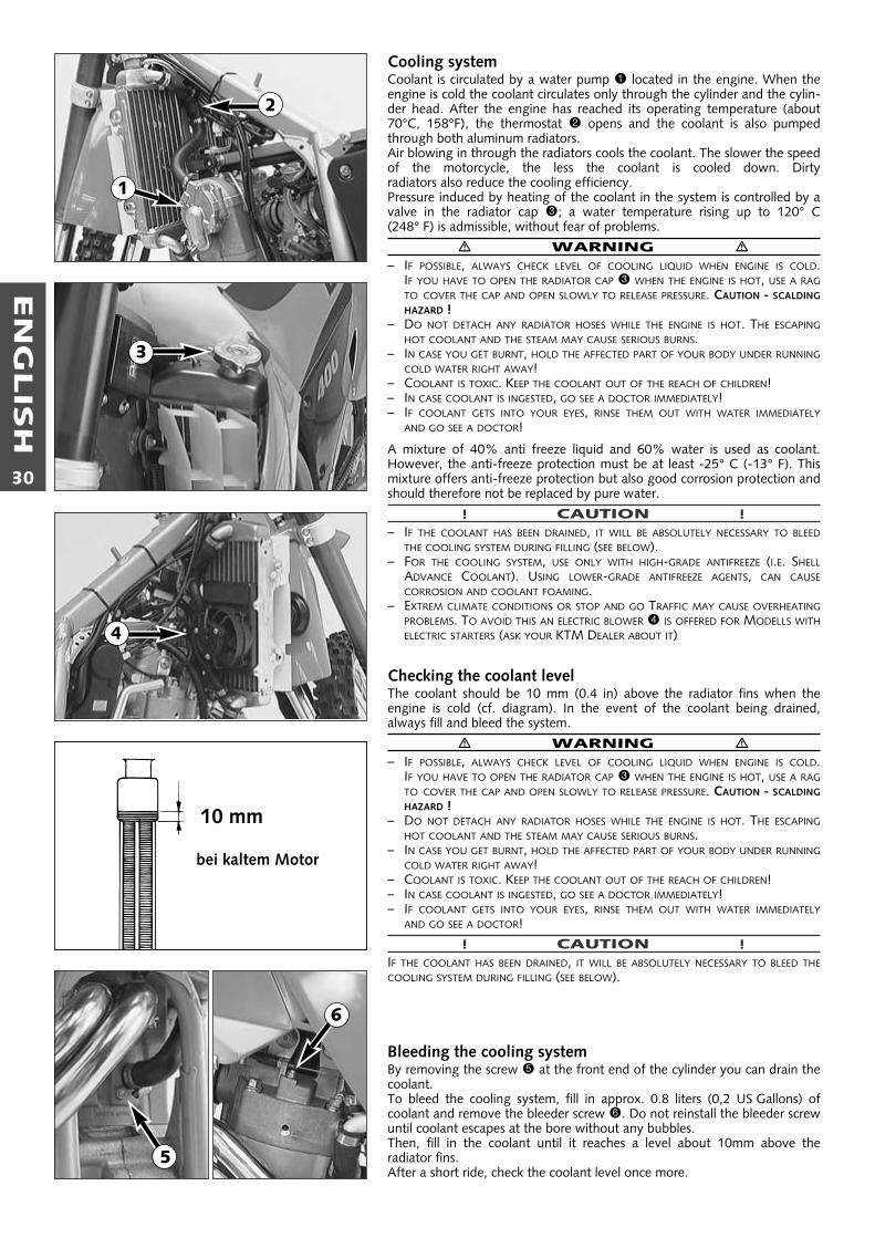
Cooling systemCoolant is circulated by a water pump 1 located in the engine. When theengine is cold the coolant circulates only through the cylinder and the cylin-der head. After the engine has reached its operating temperature (about70°C, 158°F), the thermostat 2 opens and the coolant is also pumpedthrough both aluminum radiators.Air blowing in through the radiators cools the coolant. The slower the speedof the motorcycle, the less the coolant is cooled down. Dirty radiators also reduce the cooling efficiency.Pressure induced by heating of the coolant in the system is controlled by avalve in the radiator cap 3; a water temperature rising up to 120° C (248° F) is admissible, without fear of problems.
� WARNING �– IF POSSIBLE, ALWAYS CHECK LEVEL OF COOLING LIQUID WHEN ENGINE IS COLD.
IF YOU HAVE TO OPEN THE RADIATOR CAP 3 WHEN THE ENGINE IS HOT, USE A RAGTO COVER THE CAP AND OPEN SLOWLY TO RELEASE PRESSURE. CAUTION - SCALDING
HAZARD !– DO NOT DETACH ANY RADIATOR HOSES WHILE THE ENGINE IS HOT. THE ESCAPING
HOT COOLANT AND THE STEAM MAY CAUSE SERIOUS BURNS.– IN CASE YOU GET BURNT, HOLD THE AFFECTED PART OF YOUR BODY UNDER RUNNING
COLD WATER RIGHT AWAY!– COOLANT IS TOXIC. KEEP THE COOLANT OUT OF THE REACH OF CHILDREN!– IN CASE COOLANT IS INGESTED, GO SEE A DOCTOR IMMEDIATELY!– IF COOLANT GETS INTO YOUR EYES, RINSE THEM OUT WITH WATER IMMEDIATELY
AND GO SEE A DOCTOR!
A mixture of 40% anti freeze liquid and 60% water is used as coolant.However, the anti-freeze protection must be at least -25° C (-13° F). Thismixture offers anti-freeze protection but also good corrosion protection andshould therefore not be replaced by pure water.
! CAUTION !– IF THE COOLANT HAS BEEN DRAINED, IT WILL BE ABSOLUTELY NECESSARY TO BLEED
THE COOLING SYSTEM DURING FILLING (SEE BELOW).– FOR THE COOLING SYSTEM, USE ONLY WITH HIGH-GRADE ANTIFREEZE (I.E. SHELL
ADVANCE COOLANT). USING LOWER-GRADE ANTIFREEZE AGENTS, CAN CAUSECORROSION AND COOLANT FOAMING.
– EXTREM CLIMATE CONDITIONS OR STOP AND GO TRAFFIC MAY CAUSE OVERHEATINGPROBLEMS. TO AVOID THIS AN ELECTRIC BLOWER 4 IS OFFERED FOR MODELLS WITHELECTRIC STARTERS (ASK YOUR KTM DEALER ABOUT IT)
Checking the coolant levelThe coolant should be 10 mm (0.4 in) above the radiator fins when theengine is cold (cf. diagram). In the event of the coolant being drained,always fill and bleed the system.
� WARNING �– IF POSSIBLE, ALWAYS CHECK LEVEL OF COOLING LIQUID WHEN ENGINE IS COLD.
IF YOU HAVE TO OPEN THE RADIATOR CAP 3 WHEN THE ENGINE IS HOT, USE A RAGTO COVER THE CAP AND OPEN SLOWLY TO RELEASE PRESSURE. CAUTION - SCALDING
HAZARD !– DO NOT DETACH ANY RADIATOR HOSES WHILE THE ENGINE IS HOT. THE ESCAPING
HOT COOLANT AND THE STEAM MAY CAUSE SERIOUS BURNS.– IN CASE YOU GET BURNT, HOLD THE AFFECTED PART OF YOUR BODY UNDER RUNNING
COLD WATER RIGHT AWAY!– COOLANT IS TOXIC. KEEP THE COOLANT OUT OF THE REACH OF CHILDREN!– IN CASE COOLANT IS INGESTED, GO SEE A DOCTOR IMMEDIATELY!– IF COOLANT GETS INTO YOUR EYES, RINSE THEM OUT WITH WATER IMMEDIATELY
AND GO SEE A DOCTOR!
! CAUTION !IF THE COOLANT HAS BEEN DRAINED, IT WILL BE ABSOLUTELY NECESSARY TO BLEED THECOOLING SYSTEM DURING FILLING (SEE BELOW).
Bleeding the cooling systemBy removing the screw 5 at the front end of the cylinder you can drain thecoolant.To bleed the cooling system, fill in approx. 0.8 liters (0,2 US Gallons) ofcoolant and remove the bleeder screw 6. Do not reinstall the bleeder screwuntil coolant escapes at the bore without any bubbles.Then, fill in the coolant until it reaches a level about 10mm above the radiator fins.After a short ride, check the coolant level once more.
EN
GLIS
H
30
bei kaltem Motor
10 mm
1
2
3
5
4
6
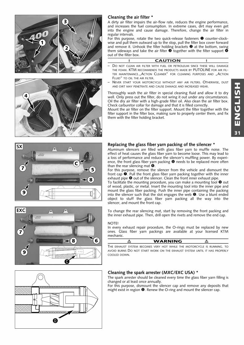
EN
GLIS
H
31
Cleaning the air filter *A dirty air filter impairs the air-flow rate, reduces the engine performance,and increases the fuel consumption. In extreme cases, dirt may even getinto the engine and cause damage. Therefore, change the air filter in regular intervals.For this purpose, rotate the two quick-release fasteners 1 counter-clock-wise and pull them outward up to the stop, pull the filter box cover forwardand remove it. Unhook the filter holding brackets 2 at the bottom, swingthem sideways and take the air filter 3 together with the filter support 4out of the filter box.
! CAUTION !– DO NOT CLEAN AIR FILTER WITH FUEL OR PETROLEUM SINCE THESE WILL DAMAGE
THE FOAM. KTM RECOMMENDS THE PRODUCTS MADE BY PUTOLINE FOR AIR FIL-TER MAINTENANCE.„ACTION CLEANER” FOR CLEANING PURPOSES AND „ACTIONFLUID” TO OIL THE AIR FILTER.
– NEVER START YOUR MOTORCYCLE WITHOUT ANY AIR FILTERS. OTHERWISE, DUSTAND DIRT MAY PENETRATE AND CAUSE DAMAGE AND INCREASED WEAR.
Thoroughly wash the air filter in special cleaning fluid and allow it to drywell. Only press out the filter, do not wring it out under any circumstances.Oil the dry air filter with a high-grade filter oil. Also clean the air filter box.Check carburetor collar for damage and that it is filled correctly.Mount the air filter on the filter support. Mount the filter together with thefilter support in the filter box, making sure to properly center them, and fixthem with the filter holding bracket.
Replacing the glass fiber yarn packing of the silencer *Aluminum silencers are filled with glass fiber yarn to muffle noise. Theeffect of heat causes the glass fiber yarn to become loose. This may lead toa loss of performance and reduce the silencer's muffling power. By experi-ence, the front glass fiber yarn packing 5 needs to be replaced more oftenthan the rear silencing mat 6.For this purpose, remove the silencer from the vehicle and dismount thefront cap 7. Pull the front glass fiber yarn packing together with the innerexhaust pipe 8 out of the silencer. Clean the front inner exhaust pipe.To facilitate the mounting procedure, you can make a mounting tool 9 outof wood, plastic, or metal. Insert the mounting tool into the inner pipe andmount the glass fiber packing. Push the inner pipe containing the packinginto the silencer such that the slot engages the web C. Use a blunt endedobject to stuff the glass fiber yarn packing all the way into the silencer, and mount the front cap.
To change the rear silencing mat, start by removing the front packing andthe inner exhaust pipe. Then, drill open the rivets and remove the end cap.
NOTE!In every exhaust repair procedure, the O-rings must be replaced by newones. Glass fiber yarn packings are available at your licensed KTM mechanic.
� WARNING �THE EXHAUST SYSTEM BECOMES VERY HOT WHILE THE MOTORCYCLE IS RUNNING. TOAVOID BURNS DO NOT START WORK ON THE EXHAUST SYSTEM UNTIL IT HAS PROPERLYCOOLED DOWN.
Cleaning the spark arrester (MXC/EXC USA) *The spark arrester should be cleaned every time the glass fiber yarn filling ischanged or at least once annually.For this purpose, dismount the silencer cap and remove any deposits thatmight exist in region D. Renew the O-ring and mount the silencer cap.
1
3
2
4
SX
EXC
5
6
7
7
8
8
9
9
C
C
D
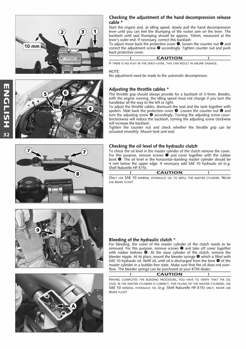
EN
GLIS
H
32
Checking the adjustment of the hand decompression releasecable *Start the engine and, at idling speed, slowly pull the hand decompressionlever until you can feel the thumping of the rocker arm on the lever. Thebacklash until said thumping should be approx. 10mm, measured at thelever's outer end. If necessary, correct this backlash.To adjust move back the protective cover 1, loosen the counter nut 2 andcorrect the adjustment screw 3 accordingly. Tighten counter nut and pushback protective cover.
! CAUTION !IF THERE IS NO PLAY IN THE DEKO-LEVER, THIS CAN RESULT IN ENGINE DAMAGE.
NOTE:No adjustment need be made to the automatic decompressor.
Adjusting the throttle cables *The throttle grip should always provide for a backlash of 3-5mm. Besides,with the engine running, the idling speed must not change if you turn thehandlebar all the way to the left or right.To adjust the throttle cables, dismount the seat and the tank together withspoilers. Slide back the protection cover 4. Loosen the counter nut 5 andturn the adjusting screw 6 accordingly. Turning the adjusting screw coun-terclockwise will reduce the backlash, turning the adjusting screw clockwisewill increase the backlash.Tighten the counter nut and check whether the throttle grip can be actuated smoothly. Mount tank and seat.
Checking the oil level of the hydraulic clutch To check the oil level in the master cylinder of the clutch remove the cover.For this purpose, remove screws 7 and cover together with the rubberboot 8. The oil level in the horizontal-standing master cylinder should be 4 mm below the upper edge. If necessary add SAE 10 hydraulic oil (e.g.Shell Naturelle HF-E15).
! CAUTION !ONLY USE SAE 10 MINERAL HYDRAULIC OIL TO REFILL THE MASTER CYLINDER. NEVERUSE BRAKE FLUID!
Bleeding of the hydraulic clutch *For bleeding, the cover of the master cylinder of the clutch needs to beremoved. For this purpose, remove screws 7 and take off cover togetherwith rubber bellows 8. At the slave cylinder of the clutch, remove the bleeder nipple. At its place, mount the bleeder syringe 9 which is filled withSAE 10 hydraulic oil. Refill oil, until oil is discharged from the bore A of themaster cylinder in a bubble-free state. Make sure that the oil does not over-flow. The bleeder syringe can be purchased at your KTM dealer.
! CAUTION !HAVING COMPLETED THE BLEEDING PROCEDURE, YOU HAVE TO VERIFY THAT THE OILLEVEL IN THE MASTER CYLINDER IS CORRECT. FOR FILLING OF THE MASTER CYLINDER, USESAE 10 MINERAL HYDRAULIC OIL (e.g. Shell Naturelle HF-E15) ONLY; NEVER USEBRAKE FLUID!
4
5 6
77
8
9
A
10 mm
12 3
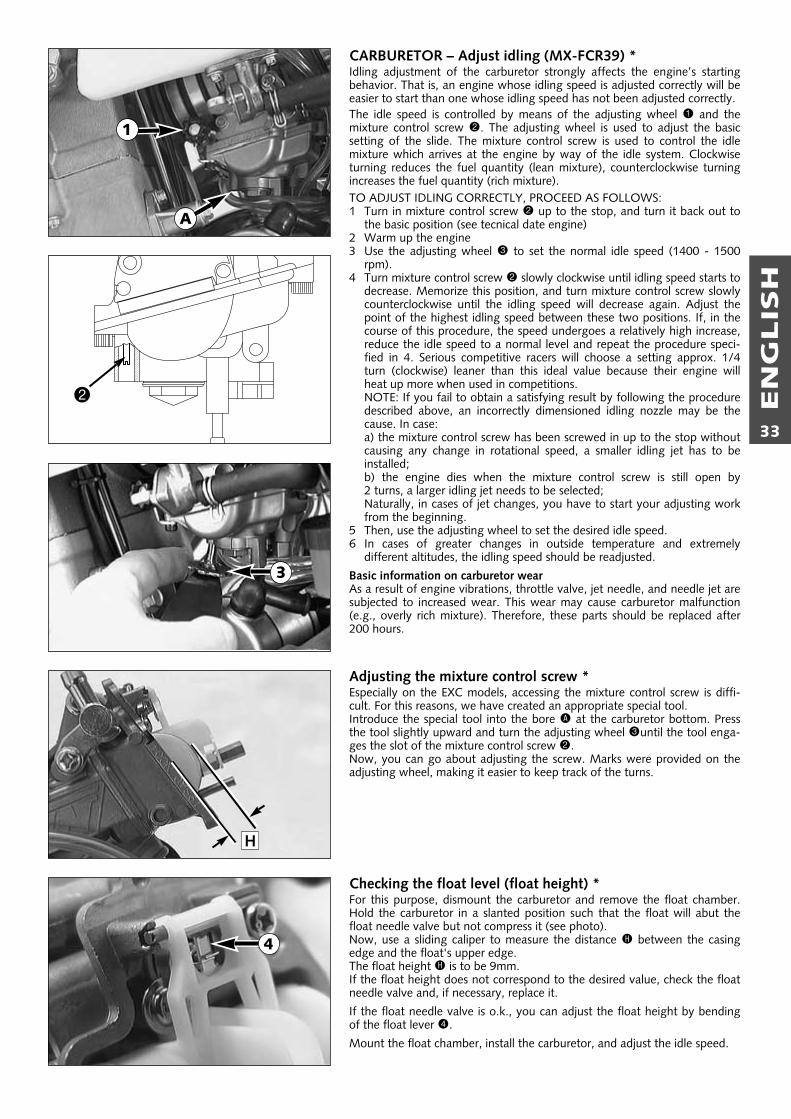
EN
GLIS
H
33
CARBURETOR – Adjust idling (MX-FCR39) *Idling adjustment of the carburetor strongly affects the engine’s startingbehavior. That is, an engine whose idling speed is adjusted correctly will beeasier to start than one whose idling speed has not been adjusted correctly.The idle speed is controlled by means of the adjusting wheel 1 and themixture control screw 2. The adjusting wheel is used to adjust the basicsetting of the slide. The mixture control screw is used to control the idlemixture which arrives at the engine by way of the idle system. Clockwiseturning reduces the fuel quantity (lean mixture), counterclockwise turningincreases the fuel quantity (rich mixture).TO ADJUST IDLING CORRECTLY, PROCEED AS FOLLOWS:1 Turn in mixture control screw 2 up to the stop, and turn it back out to
the basic position (see tecnical date engine)2 Warm up the engine3 Use the adjusting wheel 3 to set the normal idle speed (1400 - 1500
rpm).4 Turn mixture control screw 2 slowly clockwise until idling speed starts to
decrease. Memorize this position, and turn mixture control screw slowlycounterclockwise until the idling speed will decrease again. Adjust thepoint of the highest idling speed between these two positions. If, in thecourse of this procedure, the speed undergoes a relatively high increase,reduce the idle speed to a normal level and repeat the procedure speci-fied in 4. Serious competitive racers will choose a setting approx. 1/4turn (clockwise) leaner than this ideal value because their engine willheat up more when used in competitions.NOTE: If you fail to obtain a satisfying result by following the proceduredescribed above, an incorrectly dimensioned idling nozzle may be thecause. In case:a) the mixture control screw has been screwed in up to the stop withoutcausing any change in rotational speed, a smaller idling jet has to beinstalled;b) the engine dies when the mixture control screw is still open by 2 turns, a larger idling jet needs to be selected;Naturally, in cases of jet changes, you have to start your adjusting workfrom the beginning.
5 Then, use the adjusting wheel to set the desired idle speed.6 In cases of greater changes in outside temperature and extremely
different altitudes, the idling speed should be readjusted.
Basic information on carburetor wearAs a result of engine vibrations, throttle valve, jet needle, and needle jet aresubjected to increased wear. This wear may cause carburetor malfunction(e.g., overly rich mixture). Therefore, these parts should be replaced after200 hours.
Adjusting the mixture control screw *Especially on the EXC models, accessing the mixture control screw is diffi-cult. For this reasons, we have created an appropriate special tool.Introduce the special tool into the bore A at the carburetor bottom. Pressthe tool slightly upward and turn the adjusting wheel 3until the tool enga-ges the slot of the mixture control screw 2.Now, you can go about adjusting the screw. Marks were provided on theadjusting wheel, making it easier to keep track of the turns.
Checking the float level (float height) *For this purpose, dismount the carburetor and remove the float chamber.Hold the carburetor in a slanted position such that the float will abut thefloat needle valve but not compress it (see photo).Now, use a sliding caliper to measure the distance H between the casingedge and the float's upper edge.The float height H is to be 9mm.If the float height does not correspond to the desired value, check the floatneedle valve and, if necessary, replace it.
If the float needle valve is o.k., you can adjust the float height by bendingof the float lever 4.
Mount the float chamber, install the carburetor, and adjust the idle speed.
1
3
A
H
4
2
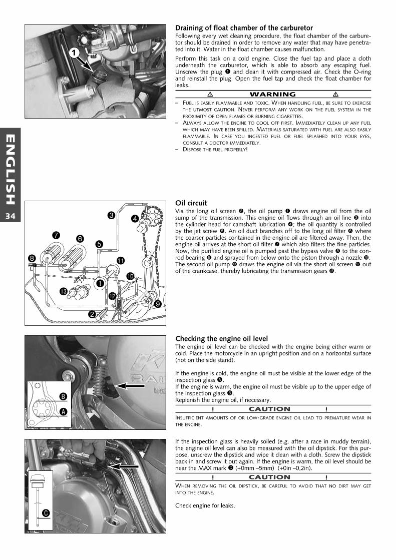
EN
GLIS
H
34
Draining of float chamber of the carburetorFollowing every wet cleaning procedure, the float chamber of the carbure-tor should be drained in order to remove any water that may have penetra-ted into it. Water in the float chamber causes malfunction.
Perform this task on a cold engine. Close the fuel tap and place a clothunderneath the carburetor, which is able to absorb any escaping fuel.Unscrew the plug 1 and clean it with compressed air. Check the O-ringand reinstall the plug. Open the fuel tap and check the float chamber forleaks.
� WARNING �– FUEL IS EASILY FLAMMABLE AND TOXIC. WHEN HANDLING FUEL, BE SURE TO EXERCISE
THE UTMOST CAUTION. NEVER PERFORM ANY WORK ON THE FUEL SYSTEM IN THEPROXIMITY OF OPEN FLAMES OR BURNING CIGARETTES.
– ALWAYS ALLOW THE ENGINE TO COOL OFF FIRST. IMMEDIATELY CLEAN UP ANY FUELWHICH MAY HAVE BEEN SPILLED. MATERIALS SATURATED WITH FUEL ARE ALSO EASILYFLAMMABLE. IN CASE YOU INGESTED FUEL OR FUEL SPLASHED INTO YOUR EYES, CONSULT A DOCTOR IMMEDIATELY.
– DISPOSE THE FUEL PROPERLY!
Oil circuitVia the long oil screen 2, the oil pump 1 draws engine oil from the oilsump of the transmission. This engine oil flows through an oil line 3 intothe cylinder head for camshaft lubrication 4; the oil quantity is controlledby the jet screw 5. An oil duct branches off to the long oil filter 6 wherethe coarser particles contained in the engine oil are filtered away. Then, theengine oil arrives at the short oil filter 7 which also filters the fine particles.Now, the purified engine oil is pumped past the bypass valve 8 to the con-rod bearing 9 and sprayed from below onto the piston through a nozzle bk.The second oil pump bl draws the engine oil via the short oil screen bm outof the crankcase, thereby lubricating the transmission gears bn.
Checking the engine oil levelThe engine oil level can be checked with the engine being either warm orcold. Place the motorcycle in an upright position and on a horizontal surface(not on the side stand).
If the engine is cold, the engine oil must be visible at the lower edge of theinspection glass A.If the engine is warm, the engine oil must be visible up to the upper edge ofthe inspection glass B.Replenish the engine oil, if necessary.
! CAUTION !INSUFFICIENT AMOUNTS OF OR LOW-GRADE ENGINE OIL LEAD TO PREMATURE WEAR INTHE ENGINE.
If the inspection glass is heavily soiled (e.g. after a race in muddy terrain),the engine oil level can also be measured with the oil dipstick. For this pur-pose, unscrew the dipstick and wipe it clean with a cloth. Screw the dipstickback in and screw it out again. If the engine is warm, the oil level should benear the MAX mark C (+0mm –5mm) (+0in –0,2in).
! CAUTION !WHEN REMOVING THE OIL DIPSTICK, BE CAREFUL TO AVOID THAT NO DIRT MAY GETINTO THE ENGINE.
Check engine for leaks.
1
2
bk
bl
bmbn
3 4
567
8
9
A
B
C
1

EN
GLIS
H
35
Engine oilOnly use fully synthetic branded oils (Shell Advance Ultra 4) meeting or sur-passing the quality requirements of API classes SG or SH (see specificationson the container).
! CAUTION !INSUFFICIENT OIL OR POOR QUALITY OIL RESULTS IN PREMATURE WEAR OF THE ENGINE.
Changing the engine oil *NOTE: WHEN CHANGING THE ENGINE OIL, IT IS NECESSARY TO CLEAN THE SHORT ANDLONG OIL SCREENS AND TO REPLACE BOTH OIL FILTERS.
Engine oil has be changed with the engine being at operating temperature.
! CAUTION !AN ENGINE AT OPERATING TEMPERATURE AND THE ENGINE OIL IT CONTAINS ARE VERYHOT - DO NOT BURN OR SCALD YOURSELF!
Place the motorcycle on a horizontal surface, remove the plug 1 and allowthe oil to drain into a receptacle.Clean plug (with magnet) thoroughly.Once the entire oil has been drained, clean the sealing surface, mount theplug together with the sealing ring and tighten it to 20 Nm (15 ft.lb).
CLEANING THE SHORT OIL SCREEN The short oil screen 2 is accommodated in the hex-socket plug 3 at theengine bottom. Insert a pin-type key into the plug and tap on the key a fewtimes with a hammer in order to relieve the stress acting on the plug. Dis-mount the oil screen, clean the components thoroughly and blow compres-sed air through them. Check the O-rings for damage and, if necessary,replace them. Mount the oil screen together with the plug again and tigh-ten the plug to 10 Nm (7 ft.lb).
CLEANING THE LONG OIL SCREENThe long oil screen is accommodated in the hexagon plug 4 adjacent theengine number. Dismount the plug together with the oil screen, clean thecomponents thoroughly and blow compressed air through them. Check theO-rings for damage and, if necessary, replace them.
To mount the long oil screen 5, place it on an approx. 300 mm (12 in) longpin-type key or a similar tool. Insert the pin-type key through the openinginto the bore of the opposite engine casing wall. Then, push the oil screeninto the engine casing as far as possible. Remove the pin-type key, mountthe plug and tighten it to 15 Nm (11 ft.lb).
! CAUTION !THE OIL SCREEN IS MOUNTED SLIGHTLY DOWNWARDS, INCORRECT FITTED THE SCREENLOOSES ITS FUNCTION AND THIS CAN CAUSE INCREASED ENGINE WEAR
� �– +0°C32°F
15W 4015W 50
10W 4010W 50
API: SG, SHTEMPERATURE
1
4
2
3
5
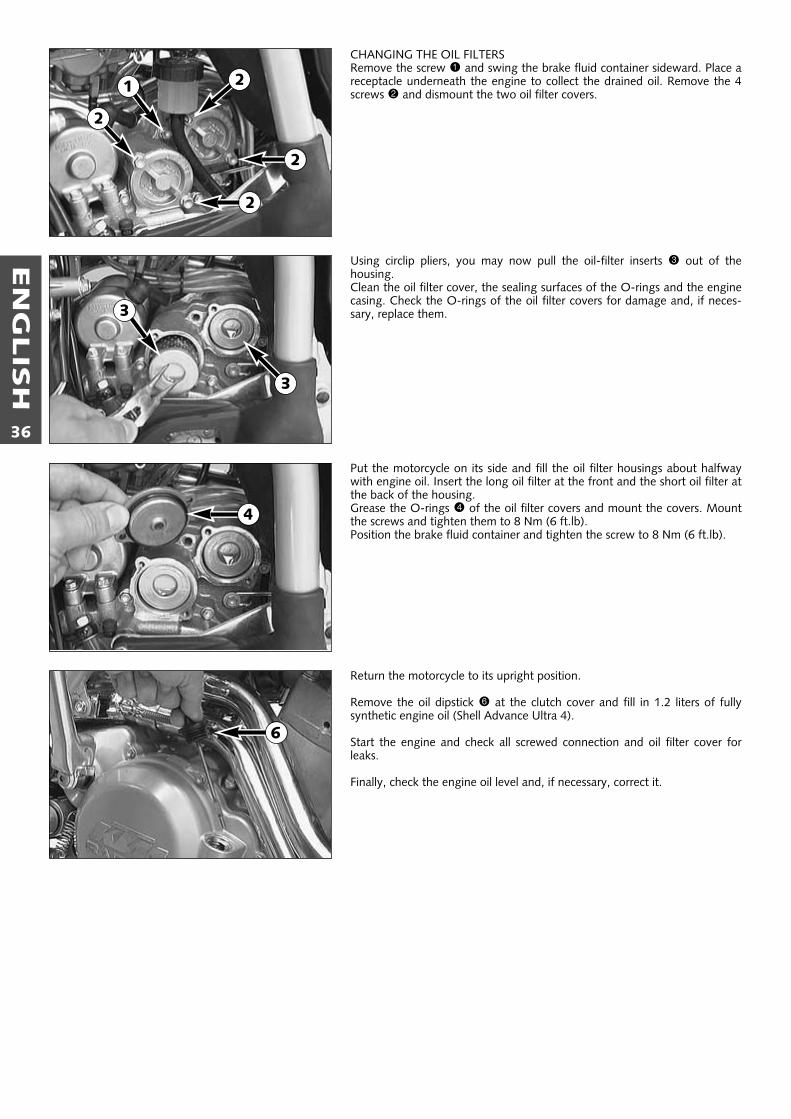
EN
GLIS
H
36
CHANGING THE OIL FILTERSRemove the screw 1 and swing the brake fluid container sideward. Place areceptacle underneath the engine to collect the drained oil. Remove the 4screws 2 and dismount the two oil filter covers.
Using circlip pliers, you may now pull the oil-filter inserts 3 out of the housing.Clean the oil filter cover, the sealing surfaces of the O-rings and the enginecasing. Check the O-rings of the oil filter covers for damage and, if neces-sary, replace them.
Put the motorcycle on its side and fill the oil filter housings about halfwaywith engine oil. Insert the long oil filter at the front and the short oil filter atthe back of the housing.Grease the O-rings 4 of the oil filter covers and mount the covers. Mountthe screws and tighten them to 8 Nm (6 ft.lb).Position the brake fluid container and tighten the screw to 8 Nm (6 ft.lb).
Return the motorcycle to its upright position.
Remove the oil dipstick 6 at the clutch cover and fill in 1.2 liters of fullysynthetic engine oil (Shell Advance Ultra 4).
Start the engine and check all screwed connection and oil filter cover forleaks.
Finally, check the engine oil level and, if necessary, correct it.
6
1
2
2
2
2
3
3
4
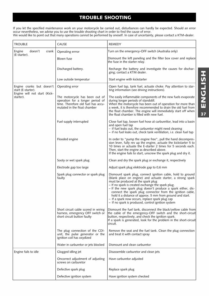
EN
GLIS
H
37
TROUBLE SHOOTING
If you let the specified maintenance work on your motorcycle be carried out, disturbances can hardly be expected. Should an erroroccur nevertheless, we advise you to use the trouble shooting chart in order to find the cause of error.We would like to point out that many operations cannot be performed by oneself. In case of uncertainty, please contact a KTM-dealer.
TROUBLE
Engine doesn’t crank (E-starter).
Engine cranks but doesn’tstart (E-starter).Engine will not start (Kick-starter).
Engine fails to idle
CAUSE
Operating errror
Blown fuse
Discharged battery.
Low outside temperatur
Operating error
The motorcycle has been out ofoperation for a longer period oftime. Therefore old fuel has accu-mulated in the float chamber
Fuel supply interrupted
Flooded engine
Sooty or wet spark plug
Electrode gap too large
Spark plug connector or spark plugfaulty
Short circuit cable scored in wiringharness, emergency OFF switch orshort circuit button faulty
The plug connection of the CDI-unit, the pulse generator or theignition coil has oxydized
Water in carburetor or jets blocked
Glogged idling jet
Oncorrect adjustment of adjusting screws on carburetor
Defective spark plug
Defective ignition system
REMEDY
Turn on the emergency-OFF switch (Australia only)
Dismount the left paneling and the filter box cover and replacethe fuse in the starter relay.
Recharge the battery and investigate the causes for dischar-ging; contact a KTM dealer.
Start engine with kickstarter
Open fuel tap, tank fuel, actuate choke. Pay attention to star-ting information (see driving instructions).
The easily inflammable components of the new fuels evaporateduring longer periods of standstill.When the motorcycle has been out of operation for more thana week, it is therefore recommended to drain the old fuel fromthe float chamber. The engine will immediately start off whenthe float chamber is filled with new fuel.
Close fuel tap, loosen fuel hose at carburettor, lead into a basinand open fuel tap – if fuel leaks out, the carburetor might need cleaning– if no fuel leaks out, check tank ventilation, i.e. clean fuel tap
In order to "pump the engine free", pull the hand decompres-sion lever, fully rev up the engine, actuate the kickstarter 5 to10 times or actuate the E-starter 2 times for 5 seconds each.Then, start the engine as described above.If the engine fails to start, unscrew the spark plug and dry it.
Clean and dry the spark plug or exchange it, respectively
Adjust spark plug elektrode gap to 0,6 mm
Dismount spark plug, connect ignition cable, hold to ground(blank place on engine) and actuate starter, a strong sparkmust be produced at the spark plug– If no spark is created exchange the spark plug.– If the new spark plug doesn't produce a spark either, dis-
connect the spark plug connector from the ignition cable,hold it a distance of approx. 5 mm from ground and start.
– If a spark now occurs, replace spark plug cap– If no spark is produced, control ignition system
Dismount the fuel tank, disconnect the black/yellow cable fromthe cable of the emergency-OFF switch and the short-circuitbutton, respectively, and check the ignition spark.If a spark is generated, look for the problem in the short-circuitcircuit.
Remove the seat and the fuel tank. Clean the plug connectionand treat it with contact spray
Dismount and clean carburetor
Disassemble carburetor and clean jets
Have carburetor adjusted
Replace spark plug
Have ignition system checked
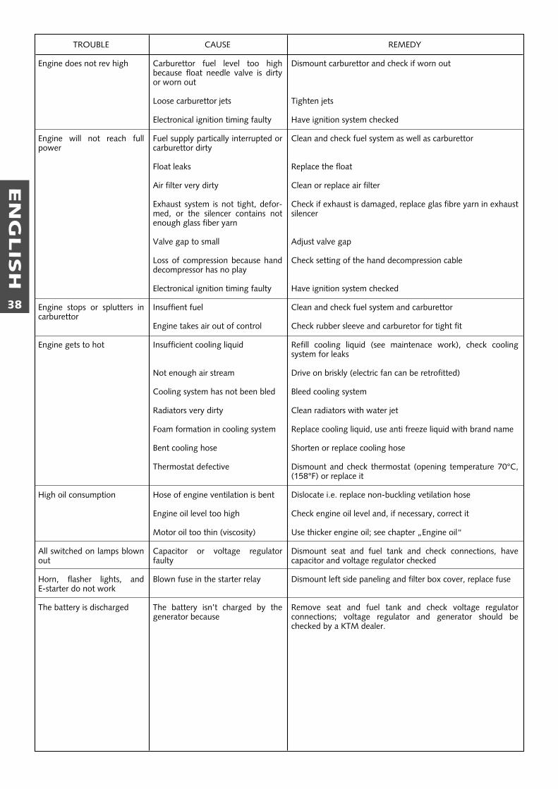
EN
GLIS
H
38
TROUBLE
Engine does not rev high
Engine will not reach fullpower
Engine stops or splutters incarburettor
Engine gets to hot
High oil consumption
All switched on lamps blownout
Horn, flasher lights, and E-starter do not work
The battery is discharged
CAUSE
Carburettor fuel level too highbecause float needle valve is dirtyor worn out
Loose carburettor jets
Electronical ignition timing faulty
Fuel supply partically interrupted orcarburettor dirty
Float leaks
Air filter very dirty
Exhaust system is not tight, defor-med, or the silencer contains notenough glass fiber yarn
Valve gap to small
Loss of compression because handdecompressor has no play
Electronical ignition timing faulty
Insuffient fuel
Engine takes air out of control
Insufficient cooling liquid
Not enough air stream
Cooling system has not been bled
Radiators very dirty
Foam formation in cooling system
Bent cooling hose
Thermostat defective
Hose of engine ventilation is bent
Engine oil level too high
Motor oil too thin (viscosity)
Capacitor or voltage regulatorfaulty
Blown fuse in the starter relay
The battery isn’t charged by thegenerator because
REMEDY
Dismount carburettor and check if worn out
Tighten jets
Have ignition system checked
Clean and check fuel system as well as carburettor
Replace the float
Clean or replace air filter
Check if exhaust is damaged, replace glas fibre yarn in exhaustsilencer
Adjust valve gap
Check setting of the hand decompression cable
Have ignition system checked
Clean and check fuel system and carburettor
Check rubber sleeve and carburetor for tight fit
Refill cooling liquid (see maintenace work), check coolingsystem for leaks
Drive on briskly (electric fan can be retrofitted)
Bleed cooling system
Clean radiators with water jet
Replace cooling liquid, use anti freeze liquid with brand name
Shorten or replace cooling hose
Dismount and check thermostat (opening temperature 70°C,(158°F) or replace it
Dislocate i.e. replace non-buckling vetilation hose
Check engine oil level and, if necessary, correct it
Use thicker engine oil; see chapter „Engine oil“
Dismount seat and fuel tank and check connections, havecapacitor and voltage regulator checked
Dismount left side paneling and filter box cover, replace fuse
Remove seat and fuel tank and check voltage regulatorconnections; voltage regulator and generator should bechecked by a KTM dealer.
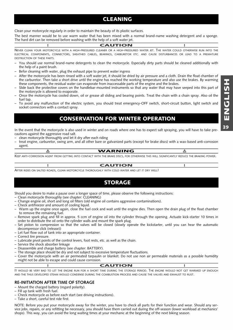
EN
GLIS
H
39
Should you desire to make a pause over a longer space of time, please observe the following instructions:– Clean motorcycle thoroughly (see chapter: CLEANING)– Change engine oil, short and long oil filters (old engine oil contains aggressive contaminations).– Check antifreezer and amount of cooling liquid.– Warm up the engine once again, close the fuel cock and wait until the engine dies. Then open the drain plug of the float chamber
to remove the remaining fuel.– Remove spark plug and fill in approx. 5 ccm of engine oil into the cylinder through the opening. Actuate kick-starter 10 times in
order to distribute the oil onto the cylinder walls and mount the spark plug.– Set piston to compression so that the valves will be closed (slowly operate the kickstarter, until you can hear the automatic
decompressor click (release))– Let fuel flow out of tank into an appropriate container.– Correct tire pressure.– Lubricate pivot points of the control levers, foot rests, etc. as well as the chain.– Service the shock absorber linkage– Disassemble and charge battery (see chapter: BATTERY).– The storage place should be dry and not subject to excessive temperature fluctuations.– Cover the motorcycle with an air permeated tarpaulin or blanket. Do not use non air permeable materials as a possible humidity
might not be able to escape and could cause corrosion.
! CAUTION !IT WOULD BE VERY BAD TO LET THE ENGINE RUN FOR A SHORT TIME DURING THE STORAGE PERIOD. THE ENGINE WOULD NOT GET WARMED UP ENOUGHAND THE THUS DEVELOPED STEAM WOULD CONDENSE DURING THE COMBUSTION PROCESS AND CAUSE THE VALVES AND EXHAUST TO RUST.
RE-INITIATION AFTER TIME OF STORAGE– Mount the charged battery (regard polarity).– Fill up tank with fresh fuel.– Check motorcycle as before each start (see driving instructions).– Take a short, careful test ride first.
NOTE: Before you put your motorcycle away for the winter, you have to check all parts for their function and wear. Should any ser-vice jobs, repairs, or any refitting be necessary, you should have them carried out during the off-season (lower workload at mechanics’shops). This way, you can avoid the long waiting times at your mechanic at the beginning of the next biking season.
STORAGE
Clean your motorcycle regularly in order to maintain the beauty of its plastic surfaces.The best manner would be to use warm water that has been mixed with a normal brand-name washing detergent and a sponge. The hard dirt can be removed before washing with the help of a soft water jet.
! CAUTION !NEVER CLEAN YOUR MOTORCYCLE WITH A HIGH-PRESSURED CLEANER OR A HIGH-PRESSURED WATER JET. THE WATER COULD OTHERWISE RUN INTO THEELECTRICAL COMPONENTS, CONNECTORS, SHEATHED CABLES, BEARINGS, CARBURETOR ETC. AND CAUSE DISTURBANCES OR LEAD TO A PREMATUREDESTRUCTION OF THESE PARTS.– You should use normal brand-name detergents to clean the motorcycle. Especially dirty parts should be cleaned additionally with
the help of a paint brush.– Befor cleaning with water, plug the exhaust pipe to prevent water ingress– After the motorcycle has been rinsed with a soft water jet, it should be dried by air pressure and a cloth. Drain the float chamber of
the carburetor. Then take a short drive until the engine has reached the working temperature and also use the brakes. By warmingthese components, the residual water can evaporate from inaccessable parts of the engine and the brakes.
– Slide back the protective covers on the handlebar-mounted instruments so that any water that may have seeped into this part ofthe motorcycle is allowed to evaporate.
– Once the motorcycle has cooled down, oil or grease all sliding and bearing points. Treat the chain with a chain spray. Also oil thefuel tap.
– To avoid any malfunction of the electric system, you should treat emergency-OFF switch, short-circuit button, light switch andsocket connectors with a contact spray.
CLEANING
In the event that the motorcycle is also used in winter and on roads where one has to expect salt spraying, you will have to take pre-cautions against the aggressive road salt.– clean motorcycle thoroughly and let it dry after each riding– treat engine, carburetor, swing arm, and all other bare or galvanized parts (except for brake discs) with a wax-based anti-corrosion
agent.
� WARNING �KEEP ANTI-CORROSION AGENT FROM GETTING INTO CONTACT WITH THE BRAKE DISCS, FOR OTHERWISE THIS WILL SIGNIFICANTLY REDUCE THE BRAKING POWER.
! CAUTION !AFTER RIDES ON SALTED ROADS, CLEAN MOTORCYCLE THOROUGHLY WITH COLD WATER AND LET IT DRY WELL!
CONSERVATION FOR WINTER OPERATION
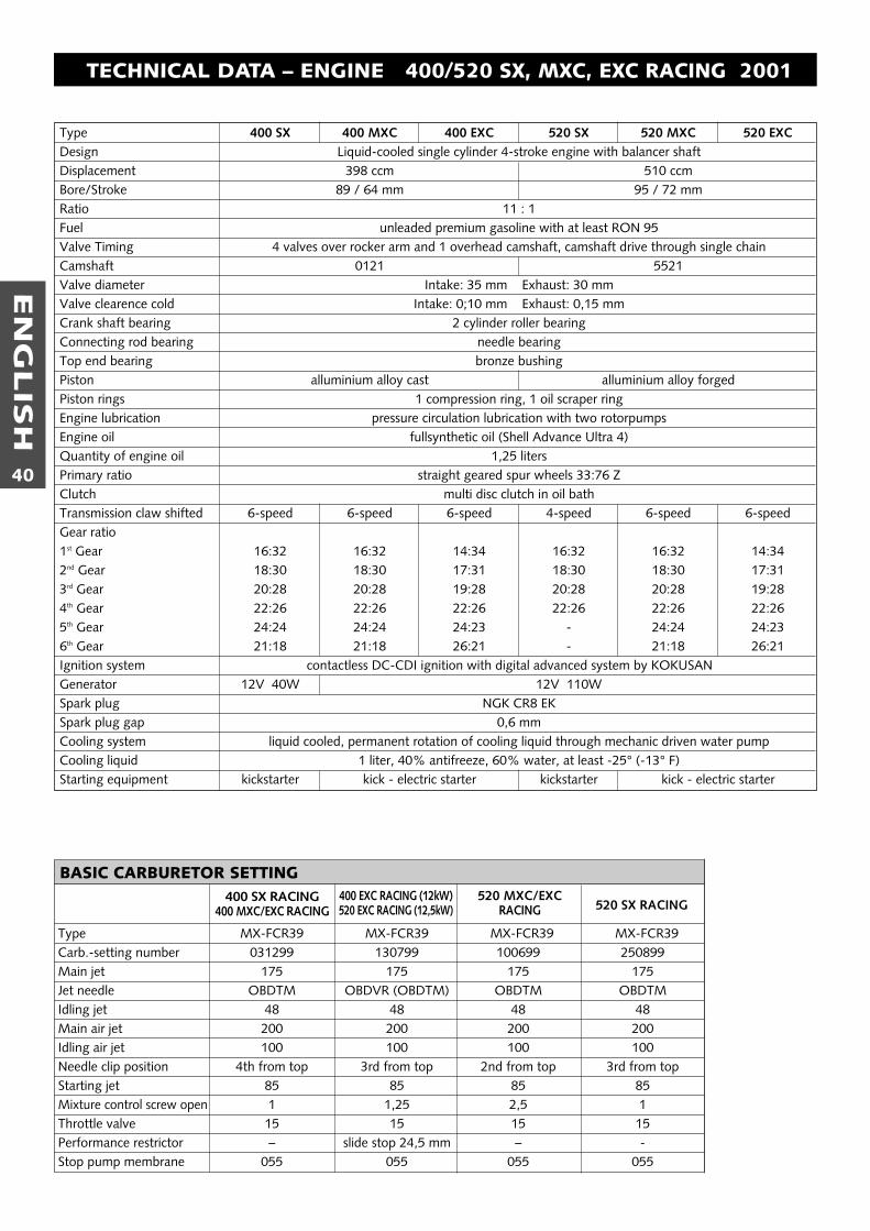
EN
GLIS
H
40
Type 400 SX 400 MXC 400 EXC 520 SX 520 MXC 520 EXCDesign Liquid-cooled single cylinder 4-stroke engine with balancer shaftDisplacement 398 ccm 510 ccmBore/Stroke 89 / 64 mm 95 / 72 mmRatio 11 : 1Fuel unleaded premium gasoline with at least RON 95Valve Timing 4 valves over rocker arm and 1 overhead camshaft, camshaft drive through single chainCamshaft 0121 5521Valve diameter Intake: 35 mm Exhaust: 30 mmValve clearence cold Intake: 0;10 mm Exhaust: 0,15 mmCrank shaft bearing 2 cylinder roller bearingConnecting rod bearing needle bearingTop end bearing bronze bushingPiston alluminium alloy cast alluminium alloy forgedPiston rings 1 compression ring, 1 oil scraper ringEngine lubrication pressure circulation lubrication with two rotorpumpsEngine oil fullsynthetic oil (Shell Advance Ultra 4)Quantity of engine oil 1,25 litersPrimary ratio straight geared spur wheels 33:76 ZClutch multi disc clutch in oil bathTransmission claw shifted 6-speed 6-speed 6-speed 4-speed 6-speed 6-speedGear ratio1st Gear 16:32 16:32 14:34 16:32 16:32 14:342nd Gear 18:30 18:30 17:31 18:30 18:30 17:313rd Gear 20:28 20:28 19:28 20:28 20:28 19:284th Gear 22:26 22:26 22:26 22:26 22:26 22:265th Gear 24:24 24:24 24:23 - 24:24 24:236th Gear 21:18 21:18 26:21 - 21:18 26:21Ignition system contactless DC-CDI ignition with digital advanced system by KOKUSANGenerator 12V 40W 12V 110WSpark plug NGK CR8 EKSpark plug gap 0,6 mmCooling system liquid cooled, permanent rotation of cooling liquid through mechanic driven water pumpCooling liquid 1 liter, 40% antifreeze, 60% water, at least -25° (-13° F)Starting equipment kickstarter kick - electric starter kickstarter kick - electric starter
TECHNICAL DATA – ENGINE 400/520 SX, MXC, EXC RACING 2001
BASIC CARBURETOR SETTING
Type MX-FCR39 MX-FCR39 MX-FCR39 MX-FCR39Carb.-setting number 031299 130799 100699 250899Main jet 175 175 175 175Jet needle OBDTM OBDVR (OBDTM) OBDTM OBDTMIdling jet 48 48 48 48Main air jet 200 200 200 200Idling air jet 100 100 100 100Needle clip position 4th from top 3rd from top 2nd from top 3rd from topStarting jet 85 85 85 85Mixture control screw open 1 1,25 2,5 1Throttle valve 15 15 15 15Performance restrictor – slide stop 24,5 mm – -Stop pump membrane 055 055 055 055
400 SX RACING400 MXC/EXC RACING
400 EXC RACING (12kW)520 EXC RACING (12,5kW)
520 MXC/EXCRACING 520 SX RACING
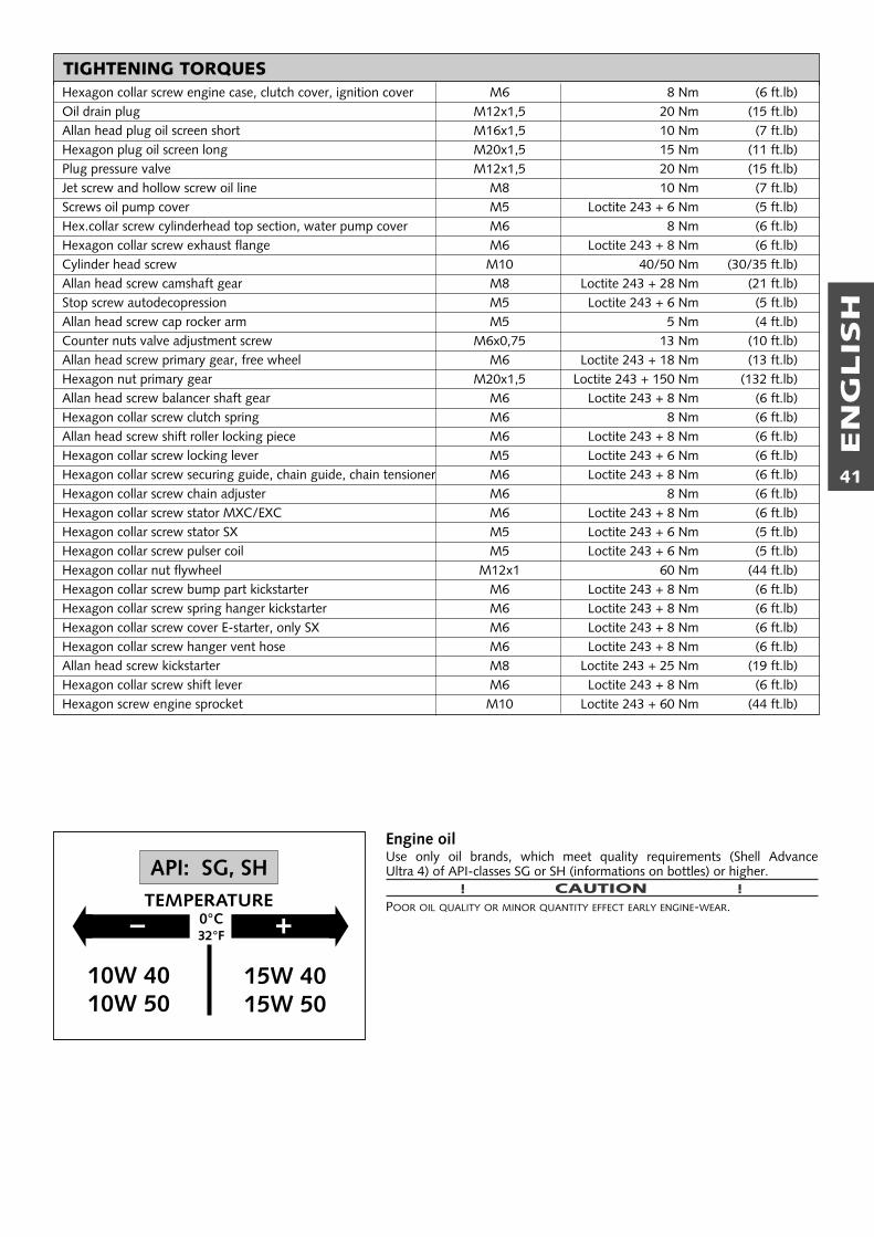
EN
GLIS
H
41
TIGHTENING TORQUESHexagon collar screw engine case, clutch cover, ignition cover M6 8 Nm (6 ft.lb)Oil drain plug M12x1,5 20 Nm (15 ft.lb)Allan head plug oil screen short M16x1,5 10 Nm (7 ft.lb)Hexagon plug oil screen long M20x1,5 15 Nm (11 ft.lb)Plug pressure valve M12x1,5 20 Nm (15 ft.lb)Jet screw and hollow screw oil line M8 10 Nm (7 ft.lb)Screws oil pump cover M5 Loctite 243 + 6 Nm (5 ft.lb)Hex.collar screw cylinderhead top section, water pump cover M6 8 Nm (6 ft.lb)Hexagon collar screw exhaust flange M6 Loctite 243 + 8 Nm (6 ft.lb)Cylinder head screw M10 40/50 Nm (30/35 ft.lb)Allan head screw camshaft gear M8 Loctite 243 + 28 Nm (21 ft.lb)Stop screw autodecopression M5 Loctite 243 + 6 Nm (5 ft.lb)Allan head screw cap rocker arm M5 5 Nm (4 ft.lb)Counter nuts valve adjustment screw M6x0,75 13 Nm (10 ft.lb)Allan head screw primary gear, free wheel M6 Loctite 243 + 18 Nm (13 ft.lb)Hexagon nut primary gear M20x1,5 Loctite 243 + 150 Nm (132 ft.lb)Allan head screw balancer shaft gear M6 Loctite 243 + 8 Nm (6 ft.lb)Hexagon collar screw clutch spring M6 8 Nm (6 ft.lb)Allan head screw shift roller locking piece M6 Loctite 243 + 8 Nm (6 ft.lb)Hexagon collar screw locking lever M5 Loctite 243 + 6 Nm (6 ft.lb)Hexagon collar screw securing guide, chain guide, chain tensioner M6 Loctite 243 + 8 Nm (6 ft.lb)Hexagon collar screw chain adjuster M6 8 Nm (6 ft.lb)Hexagon collar screw stator MXC/EXC M6 Loctite 243 + 8 Nm (6 ft.lb)Hexagon collar screw stator SX M5 Loctite 243 + 6 Nm (5 ft.lb)Hexagon collar screw pulser coil M5 Loctite 243 + 6 Nm (5 ft.lb)Hexagon collar nut flywheel M12x1 60 Nm (44 ft.lb)Hexagon collar screw bump part kickstarter M6 Loctite 243 + 8 Nm (6 ft.lb)Hexagon collar screw spring hanger kickstarter M6 Loctite 243 + 8 Nm (6 ft.lb)Hexagon collar screw cover E-starter, only SX M6 Loctite 243 + 8 Nm (6 ft.lb)Hexagon collar screw hanger vent hose M6 Loctite 243 + 8 Nm (6 ft.lb)Allan head screw kickstarter M8 Loctite 243 + 25 Nm (19 ft.lb)Hexagon collar screw shift lever M6 Loctite 243 + 8 Nm (6 ft.lb)Hexagon screw engine sprocket M10 Loctite 243 + 60 Nm (44 ft.lb)
� �– +0°C32°F
15W 4015W 50
10W 4010W 50
API: SG, SHTEMPERATURE
Engine oilUse only oil brands, which meet quality requirements (Shell Advance Ultra 4) of API-classes SG or SH (informations on bottles) or higher.
! CAUTION !POOR OIL QUALITY OR MINOR QUANTITY EFFECT EARLY ENGINE-WEAR.
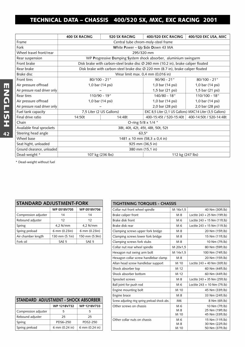
EN
GLIS
H
42
TECHNICAL DATA – CHASSIS 400/520 SX, MXC, EXC RACING 2001
WP 1218V732 WP 1218V733
Compression adjuster 5 5
Rebound adjuster 25 25
Spring PDS6–250 PDS2-250
Spring preload 6 mm (0.24 in) 6 mm (0.24 in)
STANDARD ADJUSTMENT - SHOCK ABSORBER
WP 0518V705 WP 0518V706
Compression adjuster 14 14
Rebound adjuster 12 12
Spring 4,2 N/mm 4,2 N/mm
Spring preload 6 mm (0.23in) 6 mm (0.23in)
Air chamber length 130 mm (5.1in) 150 mm (5.9in)
Fork oil SAE 5 SAE 5
STANDARD ADJUSTMENT-FORKCollar nut front wheel spindle M 16x1,5 40 Nm (30ft.lb)
Brake caliper front M 8 Loctite 243 + 25 Nm (19ft.lb)
Brake disk front M 6 Loctite 243 + 15 Nm (11ft.lb)
Brake disk rear M 6 Loctite 243 + 15 Nm (11ft.lb)
Clamping screws upper fork bridge M 8 20 Nm (15ft.lb)
Clamping screws lower fork bridge M 8 15 Nm (11ft.lb)
Clamping screws fork stubs M 8 10 Nm (7ft.lb)
Collar nut rear wheel spindle M 20x1,5 80 Nm (59ft.lb)
Hexagon nut swing arm bolt M 14x1,5 100 Nm (74ft.lb)
Hexagon collar screw handlebar clamp M 8 20 Nm (15ft.lb)
Allan head screw handlebar support M 10 Loctite 243 + 40 Nm (30ft.lb)
Shock absorber top M 12 60 Nm (44ft.lb)
Shock absorber bottom M 12 60 Nm (44ft.lb)
Sprocket screws M 8 Loctite 243 + 35 Nm (25ft.lb)
Ball joint for push rod M 6 Loctite 243 + 10 Nm (7ft.lb)
Engine mounting bolt M 10 45 Nm (33ft.lb)
Engine brace M 8 33 Nm (24ft.lb)
Screw adjusting ring spring preload shock abs. M6 8 Nm (6ft.lb)
Other screws on chassis M 6 10 Nm (7ft.lb)M 8 25 Nm (19ft.lb)M 10 45 Nm (33ft.lb)
Other collar nuts on chassis M 6 15 Nm (11ft.lb)M 8 30 Nm (22ft.lb)M 10 50 Nm (37ft.lb)
TIGHTENING TORQUES - CHASSIS
400 SX RACING 520 SX RACING 400/520 EXC RACING 400/520 EXC USA, MXCFrame Central tube chrom-moly-steel frameFork White Power – Up Side Down 43 MAWheel travel front/rear 295/320 mmRear suspension WP Progressive Damping System shock absorber, aluminium swingarmFront brake Disk brake with carbon-steel brake disc Ø 260 mm (10.2 in), brake caliper floatedRear brake Disk brake with carbon-steel brake disc Ø 220 mm (8.7 in), brake caliper floatedBrake disc Wear limit max. 0,4 mm (0,016 in)Front tires 80/100 - 21“ 90/90 - 21“ 80/100 - 21“Air pressure offroad 1,0 bar (14 psi) 1,0 bar (14 psi) 1,0 bar (14 psi)Air pressure road driver only – 1,5 bar (21 psi) 1,5 bar (21 psi)Rear tires 110/90 - 19“ 140/80 - 18“ 110/100 - 18“Air pressure offroad 1,0 bar (14 psi) 1,0 bar (14 psi) 1,0 bar (14 psi)Air pressure road driver only – 2,0 bar (28 psi) 2,0 bar (28 psi)Fuel tank capacity 7,5 Liter (2 US Gallons) EXC 8,5 Liter (2,1 US Gallons) MXC14 Liter (3,5 Gallons)Final drive ratio 14:50t 14:48t 400-15:45t / 520-15:40t 400-14:50t / 520-14:48tChain O-ring 5/8 x 1/4 "Available final sprockets 38t, 40t, 42t, 45t, 48t, 50t, 52tSteering head angle 63,5°Wheel base 1481 ± 10 mm (58,3 ± 0,4 in)Seat hight, unloaded 925 mm (36,5 in)Ground clearance, unloaded 380 mm (15,1 in)Dead-weight * 107 kg (236 lbs) 112 kg (247 lbs)
* Dead-weight without fuel
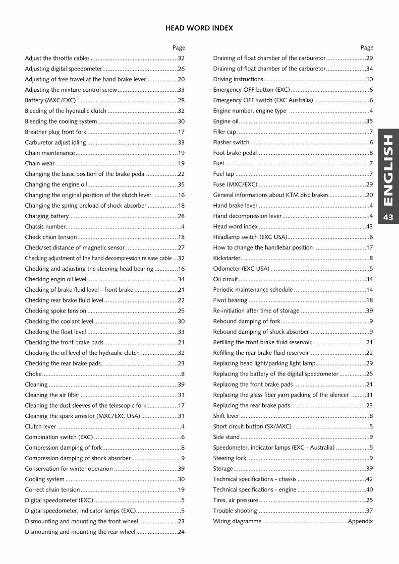
EN
GLIS
H
43
Page
Adjust the throttle cables ....................................................32
Adjusting digital speedometer.............................................26
Adjusting of free travel at the hand brake lever...................20
Adjusting the mixture control screw....................................33
Battery (MXC/EXC) ............................................................28
Bleeding of the hydraulic clutch ..........................................32
Bleeding the cooling system................................................30
Breather plug front fork ......................................................17
Carburetor adjust idling ......................................................33
Chain maintenance .............................................................19
Chain wear .........................................................................19
Changing the basic position of the brake pedal...................22
Changing the engine oil......................................................35
Changing the original position of the clutch lever ..............16
Changing the spring preload of shock absorber ..................18
Charging battery.................................................................28
Chassis number.....................................................................4
Check chain tension............................................................18
Check/set distance of magnetic sensor ...............................27
Checking adjustment of the hand decompression release cable ...32
Checking and adjusting the steering head bearing ..............16
Checking engin oil level ......................................................34
Checking of brake fluid level - front brake ..........................21
Checking rear brake fluid level ............................................22
Checking spoke tension ......................................................25
Checking the coolant level ..................................................30
Checking the float level ......................................................33
Checking the front brake pads ............................................21
Checking the oil level of the hydraulic clutch ......................32
Checking the rear brake pads..............................................23
Choke...................................................................................8
Cleaning .............................................................................39
Cleaning the air filter ..........................................................31
Cleaning the dust sleeves of the telescopic fork ..................17
Cleaning the spark arrestor (MXC/EXC USA) ......................31
Clutch lever .........................................................................4
Combination switch (EXC) ....................................................6
Compression damping of fork...............................................8
Compression damping of shock absorber..............................9
Conservation for winter operarion ......................................39
Cooling system ...................................................................30
Correct chain tension ..........................................................19
Digital speedometer (EXC) ....................................................5
Digital speedometer, indicator lamps (EXC)...........................5
Dismounting and mounting the front wheel .......................23
Dismounting and mounting the rear wheel .........................24
Page
Draining of float chamber of the carburetor........................29
Draining of float chamber of the carburetor........................34
Driving instructions .............................................................10
Emergency OFF button (EXC) ...............................................6
Emergency OFF switch (EXC Australia) .................................6
Engine number, engine type ................................................4
Engine oil............................................................................35
Filler cap ...............................................................................7
Flasher switch .......................................................................6
Foot brake pedal...................................................................8
Fuel ......................................................................................7
Fuel tap ................................................................................7
Fuse (MXC/EXC) ................................................................29
General informations about KTM disc brakes ......................20
Hand brake lever ..................................................................4
Hand decompression lever ....................................................4
Head word index ................................................................43
Headlamp switch (EXC USA).................................................6
How to change the handlebar position ...............................17
Kickstarter.............................................................................8
Odometer (EXC USA) ...........................................................5
Oil circuit ............................................................................34
Periodic maintenance schedule ...........................................14
Pivot bearing ......................................................................18
Re-initiation after time of storage .......................................39
Rebound damping of fork.....................................................9
Rebound damping of shock absorber....................................9
Refilling the front brake fluid reservoir ................................21
Refilling the rear brake fluid reservoir..................................22
Replacing head light/parking light lamp..............................29
Replacing the battery of the digital speedometer ................25
Replacing the front brake pads ...........................................21
Replacing the glass fiber yarn packing of the silencer .........31
Replacing the rear brake pads .............................................23
Shift lever .............................................................................8
Short circuit button (SX/MXC) ..............................................5
Side stand.............................................................................9
Speedometer, indicator lamps (EXC - Australia) ....................5
Steering lock .........................................................................9
Storage ...............................................................................39
Technical specifications - chassis .........................................42
Technical specifications - engine .........................................40
Tires, air pressure ................................................................25
Trouble shooting.................................................................37
Wiring diagramme ...................................................Appendix
HEAD WORD INDEX

KTM
SP
OR
TM
OTO
RC
YC
LE
AG
5230 Mattighofen
Austria
Internet: ww
w.ktm
.at
320598