Embed Size (px)
Citation preview
32
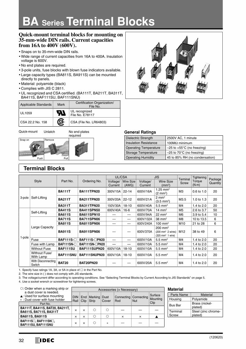
BA Series Terminal BlocksQuick-mount terminal blocks for mounting on 35-mm-wide DIN rails. Current capacities from 16A to 400V (600V).
Snaps on to 35-mm-wide DIN rails. •Wide range of current capacities from 16A to 400A. Insulation •voltage is 600V.No end plates are required. •3-pole units, fuse blocks with blown fuse indicators available. •Large capacity types (BA811S, BA911S) can be mounted •directly to panels.Material: polyamide (black) •Complies with JIS C 2811. •UL recognized and CSA certified. (BA111T, BA211T, BA311T, •BA411S, BAF111SU, BAF111SNU)
Applicable Standards Mark Certification Organization/File No.
UL1059 UL recognizedFile No. E78117
CSA 22.2 No. 158 CSA (File No. LR64803)
General RatingsDielectric Strength 2500V AC, 1 minute
Insulation Resistance 100MΩ minimumOperating Tempera ture –25 to +55°C (no freezing)
Storage Temperature –25 to 70°C (no freezing)
Operating Humidity 45 to 85% RH (no condensation)
No end plates required
Quick-mount Unlatch
Snap on
Push Pull
Remove
Terminal Blocks
Style Part No. Ordering No.UL/CSA JIS
Terminal Screw
Tightening Torque (N·m)
Package QuantityVoltage/
CurrentWire Size
(AWG)Voltage/Current
Wire Size (mm2)
3-pole Self-Lifting
BA111T BA111TPN20 300V/15A 22-14 600V/16A 1.25 mm2 (2 mm2) M3 0.6 to 1.0 20
BA211T BA211TPN20 300V/20A 22-12 600V/21A 2 mm2 (3.5 mm2) M3.5 1.0 to 1.3 20
BA311T BA311TPN20 150V/30A 18-10 600V/40A 5.5 mm2 M4 1.4 to 2.0 20
1-pole
Self-LiftingBA411S BA411SPN50 600V/40A 16-6 600V/70A 14 mm2 M5 2.6 to 3.7 50BA611S BA611SPN10 — — 600V/94A 22 mm2 M6 3.9 to 5.4 10
Large Capacity
BA711S BA711SPN06 — — 600V/132A 38 mm2 M8 10 to 13.5 6BA811S BA811SPN06 — — 600V/240A 100 mm2 M10 21 to 28 6
BA911S BA911SPN06 — — 600V/370A200 mm2 (200 mm2 2 wires) (325 mm2 1 wire)
M12 38 to 49 6
Fuse BAF111S- BAF111S-PN20 — — 600V/10A 5.5 mm2 M4 1.4 to 2.0 20Fuse with Lamp BAF111SN- BAF111SN-PN20 — — 600V/10A 5.5 mm2 M4 1.4 to 2.0 20Without Fuse BAF111SU BAF111SUPN20 600V/10A 18-10 600V/10A 5.5 mm2 M4 1.4 to 2.0 20WIthout Fuse/With Lamp BAF111SNU BAF111SNUPN20 600V/10A 18-10 600V/10A 5.5 mm2 M4 1.4 to 2.0 20
With Disconnecting Switch BAT20 BAT20PN20 — — 600V/20A 5.5 mm2 M4 1.4 to 2.0 20
1. Specify fuse ratings 1A, 3A, or 5A in place of in the Part No. 2. The wire size in ( ) does not comply with JIS standards.3. The voltage/current differ according to operating conditions. See “Selecting Terminal Blocks by Current According to JIS Standards” on page 5. 4. Use a socket wrench or screwdriver for tightening screws.
MaterialParts Name Material
Housing Polyamide
Bus Bar Brass (nickel-plated)
Terminal Screw
Steel (zinc chrome-plated)
: Order when a marking strip or a dust cover is needed.
▲: Used for surface mounting∗ : Dust cover with fuse holder
Accessories (× Necessary)
DIN Rail
End Clip
Marking Strip
Dust Cover
Connecting Rod
Connecting Nut
Surface Mounting ClipPart No.
BA111T, BA411S, BAT20, BA211T, BA611S, BA711S, BA311T × × — — —
BA811S, BA911S × × × × ▲
BAF111S, BAF111SN, BAF111SU, BAF111SNU × × ∗ — — —
(120620)
33
BA Series Terminal Blocks
6.6 max.
ø3.2 min.
5 max. 3.3 min.
6-M
3 S
crew Dust Cover
Whe
n us
ing
BA
A/B
AP
: 32
6.77.9 7.9
25 38.5
2
20.0
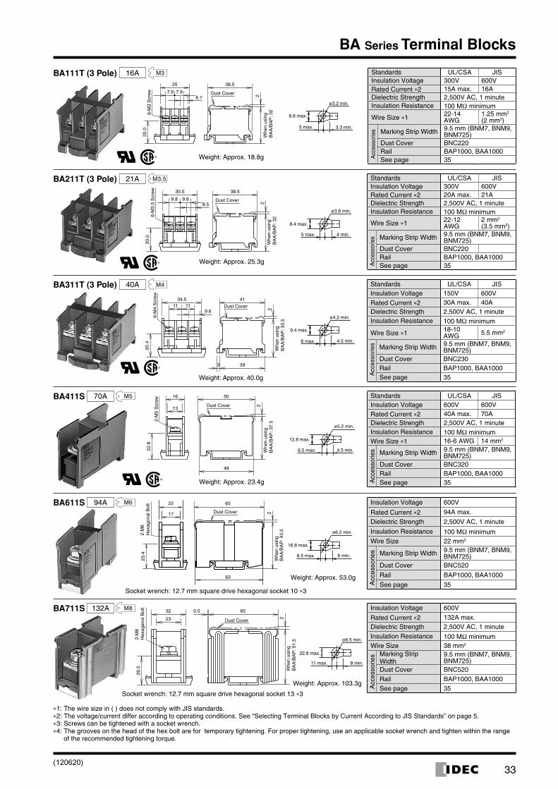
BA111T (3 Pole) 16A M3 Standards UL/CSA JISInsulation Voltage 300V 600VRated Current ∗2 15A max. 16ADielectric Strength 2,500V AC, 1 minute Insulation Resistance 100 MΩ minimum
Wire Size ∗1 22-14 AWG
1.25 mm2 (2 mm2)
Acc
esso
ries Marking Strip Width 9.5 mm (BNM7, BNM9,
BNM725)Dust Cover BNC220Rail BAP1000, BAA1000See page 35Weight: Approx. 18.8g
38.5
8.59.89.8
30.5
2Dust Cover
20.0
Whe
n us
ing
BA
A/B
AP
: 326-
M3.
5 S
crew
8.4 max.
ø3.6 min.
5 max. 4 min.
Standards UL/CSA JISInsulation Voltage 300V 600VRated Current ∗2 20A max. 21ADielectric Strength 2,500V AC, 1 minuteInsulation Resistance 100 MΩ minimum
Wire Size ∗1 22-12 AWG
2 mm2 (3.5 mm2)
Acc
esso
ries Marking Strip Width 9.5 mm (BNM7, BNM9,
BNM725)Dust Cover BNC220Rail BAP1000, BAA1000See page 35
Weight: Approx. 25.3g
BA211T (3 Pole) 21A M3.5
9.61111
34.5 41
2
393
20.4
6-M
4 S
crew
Dust Cover
Whe
n us
ing
BA
A/B
AP
: 33.
5
4.5 min.
9.4 max.
ø4.2 min.
6 max.
Standards UL/CSA JISInsulation Voltage 150V 600V
Rated Current ∗2 30A max. 40ADielectric Strength 2,500V AC, 1 minute Insulation Resistance 100 MΩ minimum
Wire Size ∗1 18-10 AWG 5.5 mm2
Acc
esso
ries Marking Strip Width 9.5 mm (BNM7, BNM9, BNM725)
Dust Cover BNC230Rail BAP1000, BAA1000See page 35
BA311T (3 Pole) 40A M4
Weight: Approx. 40.0g
13
16
48
50
2
22.8
2-M
5 S
crew
Dust Cover
Whe
n us
ing
BA
A/B
AP
: 37.
5
4.5 min.6.5 max.
ø5.2 min.
12.8 max.
BA411S 70A M5 Standards UL/CSA JISInsulation Voltage 600V 600VRated Current ∗2 40A max. 70ADielectric Strength 2,500V AC, 1 minute Insulation Resistance 100 MΩ minimumWire Size ∗1 16-6 AWG 14 mm2
Acc
esso
ries Marking Strip Width 9.5 mm (BNM7, BNM9,
BNM725)Dust Cover BNC320Rail BAP1000, BAA1000See page 35Weight: Approx. 23.4g
22 65
63
217
23.4
2-M
6H
exag
onal
Bol
t
Dust Cover
Whe
n us
ing
BA
A/B
AP
: 43.
5
6 min.8.5 max.
ø6.2 min.
16.8 max.
BA611S 94A M6 Insulation Voltage 600V
Rated Current ∗2 94A max.
Dielectric Strength 2,500V AC, 1 minute
Insulation Resistance 100 MΩ minimumWire Size 22 mm2
Acc
esso
ries Marking Strip Width 9.5 mm (BNM7, BNM9,
BNM725)Dust Cover BNC520
Rail BAP1000, BAA1000
See page 35Weight: Approx. 53.0g
Socket wrench: 12.7 mm square drive hexagonal socket 10 ∗3
23
32 650.5
2
26.5
2-M
8 H
exag
anol
Bol
t
Dust Cover
Whe
n us
ing
BA
A/B
AP
: 51.
5
8 min.11 max.
ø8.5 min.
22.8 max.
BA711S 132A M8 Insulation Voltage 600V
Rated Current ∗2 132A max.Dielectric Strength 2,500V AC, 1 minute Insulation Resistance 100 MΩ minimumWire Size 38 mm2
Acc
esso
ries Marking Strip
Width9.5 mm (BNM7, BNM9, BNM725)
Dust Cover BNC520Rail BAP1000, BAA1000See page 35
Weight: Approx. 103.3g
Socket wrench: 12.7 mm square drive hexagonal socket 13 ∗3
∗1: The wire size in ( ) does not comply with JIS standards.∗2: The voltage/current differ according to operating conditions. See “Selecting Terminal Blocks by Current According to JIS Standards” on page 5. ∗3: Screws can be tightened with a socket wrench.∗4: The grooves on the head of the hex bolt are for temporary tightening. For proper tightening, use an applicable socket wrench and tighten within the range
of the recommended tightening torque.
(120620)
34
BA Series Terminal Blocks
Dust Cover
Surface Mounting Clip (BAL3) Connecting Rod/Nut
33
42 85
601.
5
2-M
10H
exag
onal
Bol
t
ø4.5 Hole(or M4 Screw)
94 (2P)136 (3P)
84∗ 94 (4P)
∗Use 3 surface mounting clips (BAL3) for 4-pole mounting
11 min.16 max.
ø10.5 min.
32.8 max.
Surface Mounting Clip
2-M
10H
exag
onal
Bol
t
Whe
n us
ing
BA
A/B
AP
: 61.
5
(BAL2)(BAL3)Connecting Rod/NutEnd Clip
33
42 851.
5
Dust Cover
30.5
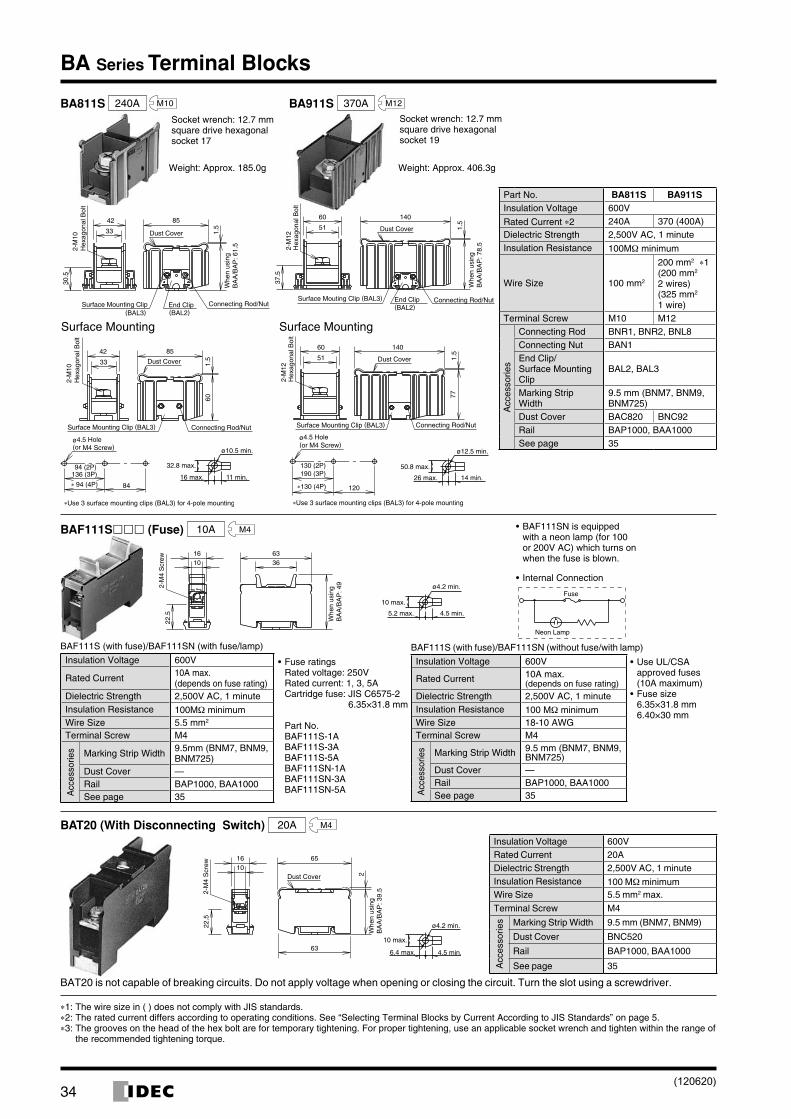
BA811S 240A M10
Surface Mounting
2-M
12H
exag
onal
Bol
tSurface Mouting Clip (BAL3) Connecting Rod/NutEnd Clip
(BAL2)
1.5
14060
51 Dust Cover
37.5
Whe
n us
ing
BA
A/B
AP
: 78.
5
2-M
12H
exag
onal
Bol
t
Surface Mounting Clip (BAL3) Connecting Rod/Nut
771.
5
14060
51 Dust Cover
ø4.5 Hole(or M4 Screw)
130 (2P)190 (3P)
120∗130 (4P)
∗Use 3 surface mounting clips (BAL3) for 4-pole mounting
14 min.26 max.
ø12.5 min.
50.8 max.
Socket wrench: 12.7 mm square drive hexagonal socket 17
Socket wrench: 12.7 mm square drive hexagonal socket 19
Surface Mounting
Weight: Approx. 185.0g Weight: Approx. 406.3g
Part No. BA811S BA911SInsulation Voltage 600V
Rated Current ∗2 240A 370 (400A)Dielectric Strength 2,500V AC, 1 minute Insulation Resistance 100MΩ minimum
Wire Size 100 mm2
200 mm2 ∗1(200 mm2 2 wires) (325 mm2 1 wire)
Terminal Screw M10 M12
Acc
esso
ries
Connecting Rod BNR1, BNR2, BNL8Connecting Nut BAN1End Clip/ Surface Mounting Clip
BAL2, BAL3
Marking Strip Width
9.5 mm (BNM7, BNM9, BNM725)
Dust Cover BAC820 BNC92Rail BAP1000, BAA1000See page 35
BA911S 370A M12
BAF111S (Fuse) 10A M4
2-M
4 S
crew
Whe
n us
ing
BA
A/B
AP
: 49
1016
3663
22.5 4.5 min.5.2 max.
10 max.
ø4.2 min.Fuse
Neon Lamp
BAF111S (with fuse)/BAF111SN (with fuse/lamp)
Insulation Voltage 600V
Rated Current 10A max. (depends on fuse rating)
Dielectric Strength 2,500V AC, 1 minute Insulation Resistance 100MΩ minimumWire Size 5.5 mm2
Terminal Screw M4
Acc
esso
ries Marking Strip Width 9.5mm (BNM7, BNM9,
BNM725)Dust Cover —Rail BAP1000, BAA1000See page 35
BAF111S (with fuse)/BAF111SN (without fuse/with lamp)
Insulation Voltage 600V
Rated Current 10A max. (depends on fuse rating)
Dielectric Strength 2,500V AC, 1 minute Insulation Resistance 100 MΩ minimumWire Size 18-10 AWGTerminal Screw M4
Acc
esso
ries Marking Strip Width 9.5 mm (BNM7, BNM9,
BNM725)Dust Cover —Rail BAP1000, BAA1000See page 35
BAF111SN is equipped •with a neon lamp (for 100 or 200V AC) which turns on when the fuse is blown.
Internal Connection•
Fuse ratings •Rated voltage: 250V Rated current: 1, 3, 5A Cartridge fuse: JIS C6575-2
6.35×31.8 mm
Part No.BAF111S-1A BAF111S-3A BAF111S-5A BAF111SN-1A BAF111SN-3A BAF111SN-5A
Use UL/CSA •approved fuses (10A maximum)Fuse size •6.35×31.8 mm 6.40×30 mm
BAT20 (With Disconnecting Switch) 20A M4
2-M
4 S
crew
Whe
n us
ing
BA
A/B
AP
: 39.
5
22.5
1610
63
65
2Dust Cover
4.5 min.6.4 max.
ø4.2 min.
10 max.
Insulation Voltage 600VRated Current 20ADielectric Strength 2,500V AC, 1 minute Insulation Resistance 100 MΩ minimumWire Size 5.5 mm2 max.
Terminal Screw M4
Acc
esso
ries Marking Strip Width 9.5 mm (BNM7, BNM9)
Dust Cover BNC520
Rail BAP1000, BAA1000
See page 35
BAT20 is not capable of breaking circuits. Do not apply voltage when opening or closing the circuit. Turn the slot using a screwdriver.
∗1: The wire size in ( ) does not comply with JIS standards.∗2: The rated current differs according to operating conditions. See “Selecting Terminal Blocks by Current According to JIS Standards” on page 5.∗3: The grooves on the head of the hex bolt are for temporary tightening. For proper tightening, use an applicable socket wrench and tighten within the range of
the recommended tightening torque.
(120620)
35
BA Series Terminal Blocks
Accessories
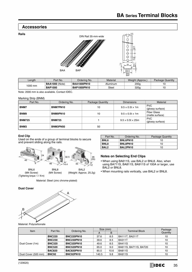
Rails
Length Part No. Ordering No. Material Weight (Approx.) Package Quantity
1000 mmBAA1000 (Note) BAA1000PN10 Aluminum 200g 10BAP1000 BAP1000PN10 Steel 320g 10
Note: 2000 mm is also available. Contact IDEC.
Marking Strip (BNM)Part No. Ordering No. Package Quantity Dimensions Material
BNM7 BNM7PN10 10 9.5 × 0.5t × 1m PVC (glossy surface)
BNM9 BNM9PN10 10 9.5 × 0.5t × 1m Fiber Glass (matte surface)
BNM725 BNM725 1 9.5 × 0.5t × 25m PVC (glossy surface)
BNM3 BNM3PN50 50
End ClipUsed on the ends of a group of terminal blocks to secure and prevent sliding along the rails.
BNL6(M4 Screw)
(Tightening torque: 1.1 N·m)
BAL2(Weight: Approx. 25.2g)
BNL8(M4 Screw)
24 32.5
14.4945
26(35)
124546
Material: Steel (zinc chrome-plated)
Part No. Ordering No. Package QuantityBNL6 BNL6PN10 10BNL8 BNL8PN10 10BAL2 BAL2PN10 10
Notes on Selecting End Clips
When using BA611S, use BAL2 or BNL8. Also, when •using BA711S, BA811S, BA911S of 100A or larger, use BAL2 or BNL8.When mounting rails vertically, use BAL2 or BNL8. •
Dust Cover
Material: Polycarbonate
Item Part No. Ordering No.Size (mm)
Terminal Block Package QuantityA B
Dust Cover (1m)
BNC220 BNC220PN10 37.6 8.5 BA111T, BA211T 10BNC230 BNC230PN10 39.6 8.5 BA311T 10BNC320 BNC320PN10 49.6 8.5 BA411S 10BNC520 BNC520PN10 65.0 9.0 BA611S, BA711S, BAT20 10BAC820 BAC820PN10 85.0 10.6 BA811S 10
Dust Cover (500 mm) BNC92 BNC92PN10 140.5 9.8 BA911S 10
BAA BAP
DIN Rail 35-mm-wide
BAABAP:27BAA:31
BA
P:1
BA
A:1
.7
BAP
12.5
12.5
5.5
35
257.5
(120620)
36
BA Series Terminal Blocks
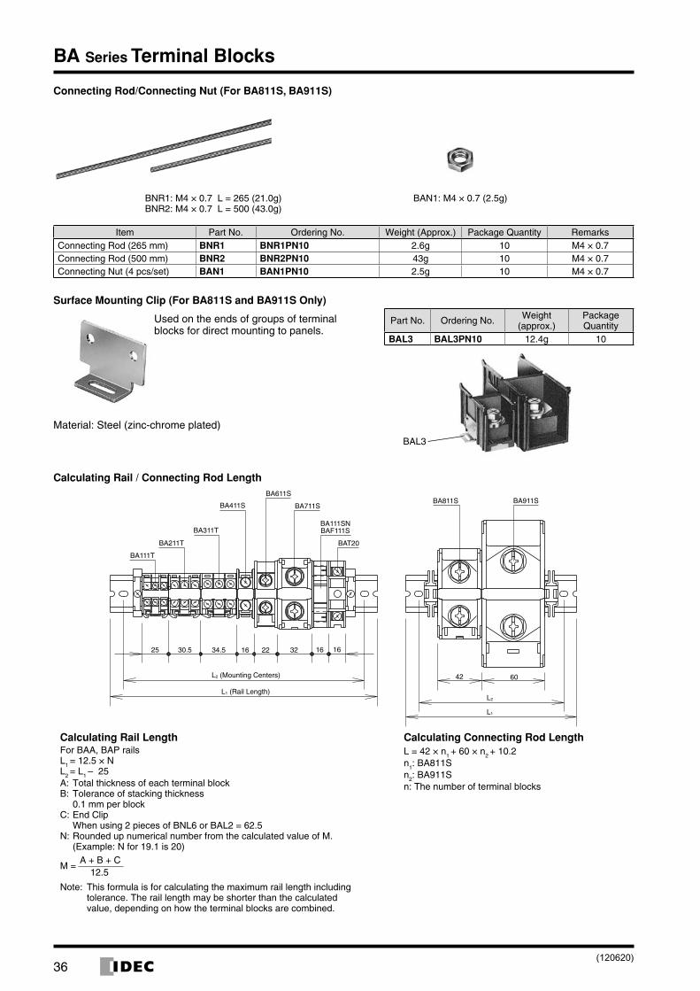
Connecting Rod/Connecting Nut (For BA811S, BA911S)
BNR1: M4 × 0.7 L = 265 (21.0g)BNR2: M4 × 0.7 L = 500 (43.0g)
BAN1: M4 × 0.7 (2.5g)
Item Part No. Ordering No. Weight (Approx.) Package Quantity RemarksConnecting Rod (265 mm) BNR1 BNR1PN10 2.6g 10 M4 × 0.7Connecting Rod (500 mm) BNR2 BNR2PN10 43g 10 M4 × 0.7Connecting Nut (4 pcs/set) BAN1 BAN1PN10 2.5g 10 M4 × 0.7
Surface Mounting Clip (For BA811S and BA911S Only)
Used on the ends of groups of terminal blocks for direct mounting to panels.
Material: Steel (zinc-chrome plated)
Part No. Ordering No. Weight (approx.)
Package Quantity
BAL3 BAL3PN10 12.4g 10
BAL3
Calculating Rail / Connecting Rod Length
BA111T
BA211T
BA111SN
BA811SBA611S
BA911S
BA311T
BAT20
BAF111S
BA711SBA411S
6042
161632221634.530.525
L2 (Mounting Centers)
L1 (Rail Length)L2
L1
Calculating Rail LengthFor BAA, BAP railsL1 = 12.5 × NL2
= L1 – 25A: Total thickness of each terminal blockB: Tolerance of stacking thickness
0.1 mm per blockC: End Clip
When using 2 pieces of BNL6 or BAL2 = 62.5N: Rounded up numerical number from the calculated value of M.
(Example: N for 19.1 is 20)
M = A + B + C 12.5
Note: This formula is for calculating the maximum rail length including tolerance. The rail length may be shorter than the calculated value, depending on how the terminal blocks are combined.
Calculating Connecting Rod LengthL = 42 × n1
+ 60 × n2 + 10.2
n1: BA811S n2: BA911S n: The number of terminal blocks
(120620)
37
BA Series Terminal Blocks
Instructions
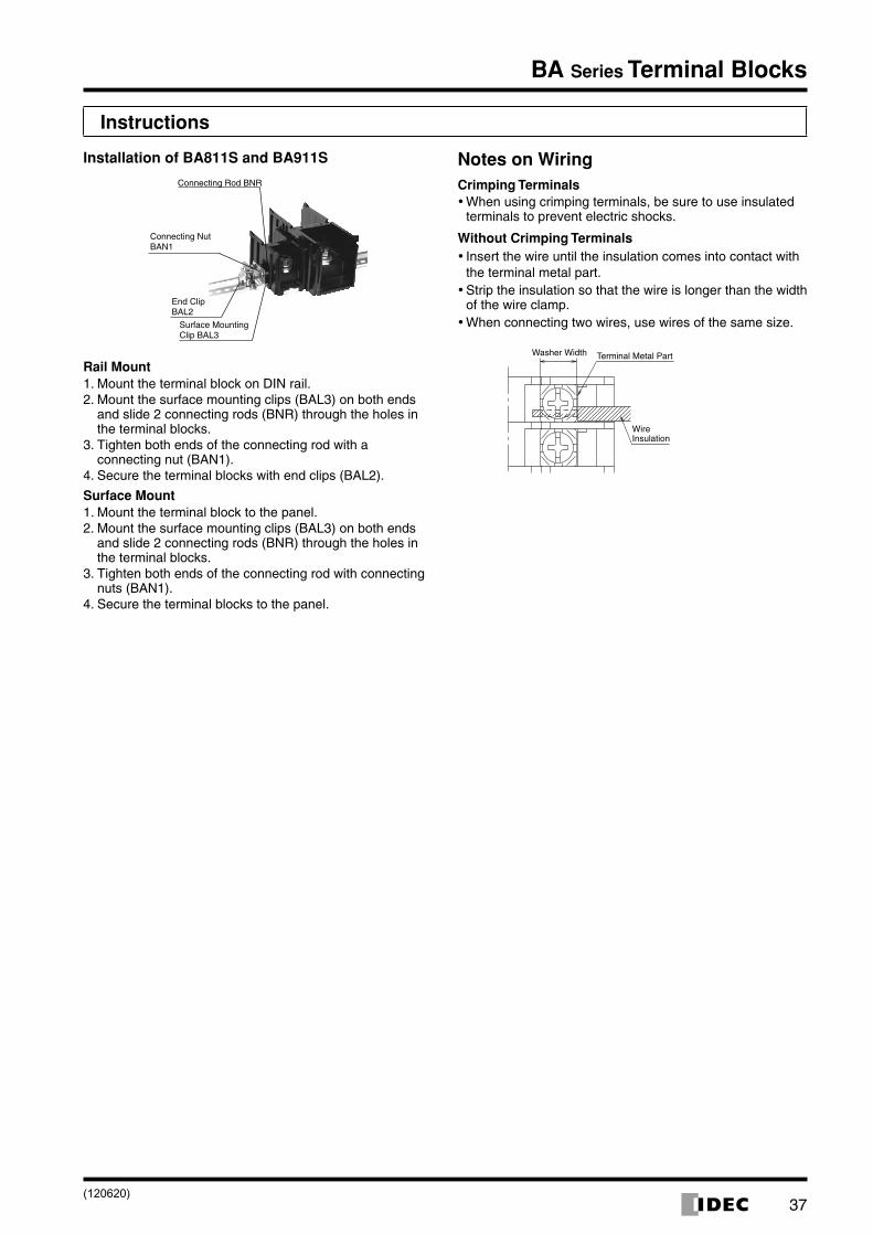
Installation of BA811S and BA911S
End Clip BAL2
Connecting Rod BNR
Connecting Nut BAN1
Surface Mounting Clip BAL3
Rail Mount1. Mount the terminal block on DIN rail.2. Mount the surface mounting clips (BAL3) on both ends
and slide 2 connecting rods (BNR) through the holes in the terminal blocks.
3. Tighten both ends of the connecting rod with a connecting nut (BAN1).
4. Secure the terminal blocks with end clips (BAL2).
Surface Mount1. Mount the terminal block to the panel.2. Mount the surface mounting clips (BAL3) on both ends
and slide 2 connecting rods (BNR) through the holes in the terminal blocks.
3. Tighten both ends of the connecting rod with connecting nuts (BAN1).
4. Secure the terminal blocks to the panel.
Notes on WiringCrimping Terminals
When using crimping terminals, be sure to use insulated •terminals to prevent electric shocks.
Without Crimping TerminalsInsert the wire until the insulation comes into contact with •the terminal metal part.Strip the insulation so that the wire is longer than the width •of the wire clamp.When connecting two wires, use wires of the same size. •
WireInsulation
Terminal Metal PartWasher Width
(120620)