Embed Size (px)
Citation preview

UNIVERSITY OF NAIROBI
INVESTIGATION OF THE PERFORMANCE OF CSTW AS A PARTIAL REPLACEMENT OF CEMENT IN CONCRETE.
BY
MATI MARTIN MULANDI REG. NO: F16/29654/2009
A project submitted as a partial fulfilment
for the requirement for the award of the degree of
BACHELOR OF SCIENCE IN CIVIL&CONSTRUCTION ENGINEERING
APRIL 2014
You created this PDF from an application that is not licensed to print to novaPDF printer (http://www.novapdf.com)

ii
DEDICATION I dedicate this project to my family who have always supported and believed in me throughout
my years of academic.
You created this PDF from an application that is not licensed to print to novaPDF printer (http://www.novapdf.com)

iii
ACKNOWLEDGEMENT I wish to express my profound and sincere gratitude to my project Supervisor Eng. E. Goro,
lecture in the department of Civil and Construction Engineering, University of Nairobi. His
inspiration, tireless guidance, advice, encouragement and constructive criticism were an
important milestone in the compilation of this report.
My sincere gratitude also goes to all the other lectures, staff members and my fellow students for
helping me gain the crucial skills and knowledge during my learning years at the University.
You created this PDF from an application that is not licensed to print to novaPDF printer (http://www.novapdf.com)

iv
ABSTRACT Over years, there has been a lot of emphasis on the conservation of the environment by
advocating for the use of renewable sources for materials in the construction industry and even in
the other fields like energy production. This project is aimed at highlighting the advantages of
using mineral admixtures in both improving the characteristics of concrete and conserving the
environment.
In the early 20th century, the composition of concrete was primarily cement, water and
aggregates. With time and use of technology, the scientists discovered the benefits that came
with use of admixtures in the concrete production. Since then, admixtures, both the chemical and
mineral admixtures, have been used in enhancing the various properties of concrete.
The aim of this research is to determine the effectiveness of the use of mineral admixtures as
micro-reinforcement in concrete. The project will single out use of mineral by-product
admixtures in the concrete production for engineering purposes. The paper will give a clear
review on the influence of the use of the mineral by-product admixtures in improving the
effective and characteristics of concrete.
Generally, use of admixtures in concrete improves its workability and strength, accelerates or
retards the setting ting and enhances concrete’s durability. This paper will also seek to clearly
outline some of the available mineral admixtures, their advantages and disadvantages in the
engineering field.
You created this PDF from an application that is not licensed to print to novaPDF printer (http://www.novapdf.com)
v
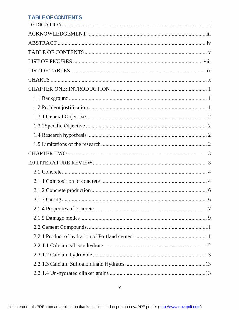
TABLE OF CONTENTS DEDICATION........................................................................................................ i
ACKNOWLEDGEMENT .................................................................................... iii
ABSTRACT ......................................................................................................... iv
TABLE OF CONTENTS ....................................................................................... v
LIST OF FIGURES ............................................................................................ viii
LIST OF TABLES ................................................................................................ ix
CHARTS ............................................................................................................... x
CHAPTER ONE: INTRODUCTION .................................................................... 1
1.1 Background .................................................................................................. 1
1.2 Problem justification .................................................................................... 1
1.3.1 General Objective...................................................................................... 2
1.3.2Specific Objective ...................................................................................... 2
1.4 Research hypothesis ..................................................................................... 2
1.5 Limitations of the research ........................................................................... 2
CHAPTER TWO ................................................................................................... 3
2.0 LITERATURE REVIEW ................................................................................. 3
2.1 Concrete ....................................................................................................... 4
2.1.1 Composition of concrete ........................................................................... 4
2.1.2 Concrete production .................................................................................. 6
2.1.3 Curing ....................................................................................................... 6
2.1.4 Properties of concrete ................................................................................ 7
2.1.5 Damage modes .......................................................................................... 9
2.2 Cement Compounds. ...................................................................................11
2.2.1 Product of hydration of Portland cement ..................................................11
2.2.1.1 Calcium silicate hydrate ........................................................................12
2.2.1.2 Calcium hydroxide ................................................................................13
2.2.1.3 Calcium Sulfoalominate Hydrates .........................................................13
2.2.1.4 Un-hydrated clinker grains ....................................................................13
You created this PDF from an application that is not licensed to print to novaPDF printer (http://www.novapdf.com)

vi
2.2.2Safety ........................................................................................................13
2.2.3 Environmental Effects ..............................................................................13
2.3 Mineral Admixtures ....................................................................................14
2.3.1Types of Mineral Admixture .....................................................................14
2.3.2 Some By-Product Mineral Admixtures.....................................................14
CHAPTER THREE: Methodology ...................................................................19
3. Experimental investigation ............................................................................19
3.1 Materials .....................................................................................................19
3.1.1 Tests on coarse aggregates .......................................................................19
3.1.2 Sieve Analysis on fine aggregates ............................................................19
3.1.3 Portland Cement .......................................................................................20
3.1.4 Water .......................................................................................................20
3.2Mix Design ..................................................................................................21
3.3 Moulding and casting ..................................................................................22
3.4 Testing methods ..........................................................................................23
3.4.1 Tests on fresh concrete .............................................................................24
3.4.1.1 Compacting Factor Test (Workability) ..................................................24
3.4.1.1 SLUMP TEST .......................................................................................25
3.4.2Mechanical Strength Tests ........................................................................26
3.4.2.1 Compressive Strength Test ....................................................................26
3.4.2.2 Split Tensile Strength Test ....................................................................28
3.4.2.3 Flexure Test-Third Point Loading Method ............................................30
CHAPTER FOUR: Results and Analysis ..............................................................33
4.1 Particle size distribution (Sieve analysis) ....................................................33
4.2 Workability tests .........................................................................................34
4.2.1 Compaction factor ....................................................................................34
4.2.2 Slump test ................................................................................................35
4.3 Cube crushing Test ......................................................................................36
4.4Tensile strength ............................................................................................38
You created this PDF from an application that is not licensed to print to novaPDF printer (http://www.novapdf.com)

vii
4.5 Flexure Strength ..........................................................................................40
CHAPTER FIVE ..................................................................................................41
5.0 Discussion ...................................................................................................41
5.1 Workability .................................................................................................41
5.1.1 Compaction ..............................................................................................41
5.1.2 Slump test ................................................................................................41
5.2 Mechanical characteristics ..........................................................................43
5.2.1 Compression strength ...............................................................................43
5.2.2 Tensile strength ........................................................................................45
5.2.3 Flexural strength ......................................................................................45
5.3 Conclusion ..................................................................................................46
5.4 Recomentations ...........................................................................................46
6.0 REFERENCES: ..............................................................................................48
7.0 APPENDIXES ……………………………………………………………...51
You created this PDF from an application that is not licensed to print to novaPDF printer (http://www.novapdf.com)

viii
LIST OF FIGURES Figure 1 Shows a concrete complex micro-structure ………………….................... …. 12
Figure 2 Showing quarry dust as a by-product at a quarry along Thika road…............. 18
Figure 3 Showing the cast cubes and beams………………………………………...... 23
Figure 4 Showing the apparatuses used in the compaction test……………………..... 24
Figure 5 Abraham’s cone……………………………………………………………… 25
Figure 6 Showing the placement of the concrete cube for compression test…………. 26
Figure 7 Testing the compression strength of a cube……………………………........ 27
Figure 8 Compression test machine………………………………………………….. 27
Figure 9 Showing cylinder splitting tesnsile test side view………………………….. 29
Figure10 Showing the four-point loading of a beam specimen……………………. … 31
You created this PDF from an application that is not licensed to print to novaPDF printer (http://www.novapdf.com)

ix
LIST OF TABLES Table 1 Typical chemical composition of quarry rock and waste tile dust…………….. 17
Table 2 shows the different grades of concrete and their application………………….. 21
Table 3 Mixture constitutes of the various concrete mixes……………………….. ….. 22
Table 4 Results of the sieve analysis on fine aggregates………………………………. 33
Table 5 Showing different consistency and compaction factor …………………......... 34
Table 6 Showing the compaction factor results…………………………………… …. 34
Table 7 Showing the slump test results……………………………………………….. 35
Table 8 Showing the compressive strength test results……………………………. …. 36
Table 9 Showing the tensile strength test results……………………………………… 38
Table 10 showing the flexural test results…………………………………………. …. 40
You created this PDF from an application that is not licensed to print to novaPDF printer (http://www.novapdf.com)

x
CHARTS Chart 1 particle distribution curve for the fine aggregates……………………………………..33
Chart 2 Compressive strength of CSTW concrete with respect to percentage replacement of
cement………………………………………………………………………………………….37
Chart 3 Tensile strength of CSTW concrete with respect to percentage replacement of
cement……………………………………………………………………………………….......39
Chart 4 Flexural strength of CSTW concrete with respect to percentage replacement of
cement…………………………………………………………………………………………...40
Chart 5 Line graph showing the7 and 28days compressive stress with varying CSTW content...51
Chart 6 Line graph showing the7 and 28days tensile stress with varying CSTW content………51
Chart 7 Line graph showing the7 and 28days flexural stress with varying CSTW content…….52
You created this PDF from an application that is not licensed to print to novaPDF printer (http://www.novapdf.com)

1
CHAPTER ONE: INTRODUCTION
1.1 Background In the most general sense of the word, cement is a binder, a substance which sets and hardens
independently, and can bind other materials together. The word "cement" traces to the Romans,
who used the term "opus caementicium" to describe masonry which resembled concrete and was
made from crushed rock with burnt lime as binder. The volcanic ash and pulverized brick
additives which were added to the burnt lime to obtain a hydraulic binder were later referred to
ascementum, cimentum, cäment and cement. Cements used in construction are characterized as
hydraulic or non-hydraulic. The most important use of cement is the production of mortar and
concrete—the bonding of natural or artificial aggregates to form a strong building material which
is durable in the face of normal environmental effects.
Concrete should not be confused with cement because the term, cement refers only to the dry
powder substance used to bind the aggregate materials of concrete.
Therefore, Concrete is a construction material composed of cement (commonly Portland cement)
as well as other cementitious materials such as fly ash and slag cement, aggregate (generally
coarse aggregate such as gravel, limestone, or granite, plus a fine aggregate such as sand), water,
and maybe admixtures. Cement solidifies and hardens after mixing with water and placement
due to a chemical process known as hydration. The water reacts with the cement, which bonds
the other components together, eventually creating a stone-like material and the reaction is
exothermic. Concrete is used to make pavements, architectural structures,foundations, and
motorways/roads, bridges/overpasses, parking structures, brick/block walls andfootings for gates,
fences and poles.
1.2 Problem justification One of the major problems facing the construction industry is environmental degradation. This
study is important in the construction industry since it promotes environmental conservation
while improving the quality of fresh concrete by use of by-products admixtures, natural mineral
admixtures. Determining the positive effects of using by-products admixtures in improving the
mechanical characteristics of concrete will help majorly in the fight to curb the environmental
degradation vice among the shareholders in the industry (Engineers, contractors, project
managers, clients/employer e.t.c.).
You created this PDF from an application that is not licensed to print to novaPDF printer (http://www.novapdf.com)

2
1.3.1 General Objective
The main aim of this research is to investigate the performance of natural mineral admixtures,
CSTW (cutting stone and tile waste), as micro reinforcement in concrete mixes when used to
improve the mechanical properties of the concrete.
1.3.2Specific Objective To determine the effects of using CSTW as a natural mineral admixture on both the
mechanical and the workability characteristics of concrete.
Establish the optimum content use of CSTW resulting to better concrete characteristics.
The objectives will be achieved by testing different concrete cubes, cylinders and beams which
have been cast with a varying natural mineral admixtures content percentage by weight of
cement. From a control of 0% natural mineral admixtures content, CSTW, then increasing the
mineral admixture as follows 5%, 10%, 15%,20% and 25%.The tests to be done are the cube
crushing tests and the flexural bending tests. Tensile strength of the by-product mineral
admixtures will be tested using the indirect method of splitting cylinder test.
1.4 Research hypothesis
Use of mineral admixture, CSTW, in the production of concrete improves the mechanical
characteristics of the hardened concrete. Addition of CSTW improves the compressive, bending
and flexural strength of hardened concrete. Reuse of CSTW in concrete mixes in partial
replacement by cement brings out with good concrete properties such as strength and durability.
In addition, use of CSTW which is a waste, helps in the conservation of the environment.
1.5 Limitations of the research Use of only locally manufactured cement as opposed to cement types from other regions. This,
therefore, limits its viability in the countries that produce similar cement as that locally available.
Due to the limited time to conduct the study, the research did not conduct a study and tests on all
the characteristics of the concrete. The research highlights only the key and crucial
characteristics of both the fresh and hardened concrete.
You created this PDF from an application that is not licensed to print to novaPDF printer (http://www.novapdf.com)

3
CHAPTER TWO
2.0 LITERATURE REVIEW Concrete is a building material that has, in the past, formed the basis our modern life. It’s one of
the most widely used construction material in the engineering filed of engineering works. This is
mainly because it has a good compressive strength, easy to place, low cost and its ingredients are
widely available. On the flipside, there are some disadvantages associated with using concrete.
They include, brittle characteristic of the concrete and its low tensile strength. In the past,
renowned scientists and researchers have burnt midnight oil in pursuit of finding better ways to
decrease the disadvantages and making use of concrete more effective and improving its
characteristics by use of admixtures.
Admixtures are defined as the material other than water, aggregates and hydraulic cement that is
used as an ingredient of concrete or motor and is added to the batch immediately before or
during the mixing.
In general, using admixtures in concrete improves its workability, accelerating or retarding
setting time, controlling development of concrete strength and enhancing durability to
deterioration process [7], categorized the admixtures in four groups; chemical admixtures, air
entraining agents, miscellaneous admixtures and mineral admixtures.
The high consumption of raw materials by the construction sector, results in chronic shortage of
building materials and the associated environmental damage. Concrete industry is particularly
important as it is not only responsible for consuming natural resources and energy but also for its
capacity of absorbing other industries waste and by-products. For this reason, the civil and
environmental engineers have been challenged to convert the industrial wastes to useful building
and construction materials.
In recent years, the construction industry has shown considerable interest in the utilization of
waste. To create products made of stone, the shape of the stone must be decorated through
cutting, shaping, and finishing, which can release dust and slurry sludge. The generated sludge
from cutting stones factories is prohibited from being discharged to the public sanitary system.
Currently, these factories hold the generated sludge in open or closed basins for two or three
weeks based on the quantity of sludge and the volume of basins. During the holding period, the
You created this PDF from an application that is not licensed to print to novaPDF printer (http://www.novapdf.com)

4
sludge losses significant amount of water by evaporation especially during hot season. At the
same time, the suspended particles will settle and condense at the bottom of the basin, which
increases its density. The contents of settling basins eventually have to be transported by trucks
and disposed off in a sanitary landfill. The sludge produced through the cutting and working of
stone is still considered an inert waste product. Once it has satisfied the required criteria for
acceptance, it is given to authorized waste dump. This sludge causes many economical and
environmental problems such as increase cost of waste storage, and transportation, disposal and
production cost. In addition, sludge affects the aesthetic and cause conflict with environmental
authorities and pressure groups. The high cost of water and the environmental problems
associated with slurry disposal has motivated the studies and researches to reduce economic
losses as well as environmental impact. As a result of environmental and economical parameters,
recycling sludge is the focus point of several ongoing researches.
2.1 Concrete Concrete is a construction material composed of cement (commonly Portland cement) as well as
other cementitious materials such as fly ash and slag cement, aggregate (generally a coarse
aggregate such as gravel, limestone, or granite, plus a fine aggregate such as sand), water, and
admixtures. Concrete solidifies and hardens after mixing with water and placement due to a
chemical process known as hydration. The water reacts with the cement, which bonds the other
components together, eventually creating a stone-like material. Concrete is used to make
pavements, architectural structures, foundations, and motorways/roads, bridges/overpasses,
parking structures, brick/block walls and footings for gates, fences and poles. Concrete is used
more than any other man-made material in the world. As of 2006, about 7.5 cubic kilometers of
concrete are made each year—more than one cubic meter for every person on Earth. Reinforced
concrete and prestressed concrete are the most widely used modern kinds of concrete functional
extensions.
2.1.1 Composition of concrete
There are many types of concrete available, created by varying the proportions of the main
ingredients below. The mix design depends on the type of structure being built, how the concrete
will be mixed and delivered, and how it will be placed to form this structure.
You created this PDF from an application that is not licensed to print to novaPDF printer (http://www.novapdf.com)

5
Cement
Portland cement is the most common type of cement in general usage. It is a basic ingredient of
concrete, mortar, and plaster. English engineer Joseph Aspdin patented Portland cement in 1824;
it was named because of its similarity in colour to Portland limestone, quarried from the English
Isle of Portland and used extensively in London architecture. It consists of a mixture of oxides of
calcium, silicon and aluminium.
Portland cement and similar materials are made by heating limestone (a source of calcium) with
clay, and grinding this product (called clinker) with a source of sulfate (most commonly
gypsum). The manufacturing of Portland cement creates about 5 percent of human CO2
emissions.
Water
Combining water with a cementitious material forms a cement paste by the process of hydration.
The cement paste glues the aggregate together, fills voids within it, and allows it to flow more
easily. Less water in the cement paste will yield a stronger, more durable concrete; more water
will give an easier-flowing concrete with a higher slump. Impure water used to make concrete
can cause problems when setting or in causing premature failure of the structure. Hydration
involves many different reactions, often occurring at the same time. As the reactions proceed, the
products of the cement hydration process gradually bond together the individual sand and gravel
particles, and other components of the concrete, to form a solid mass.
Reaction:
Cement chemist notation: C3S + H2O → CSH (gel) + CaOH
Standard notation: Ca3SiO5 + H2O → (CaO)•(SiO2)•(H2O)(gel) + Ca(OH)2
Balanced: 2Ca3SiO5 + 7H2O → 3(CaO)•2(SiO2)•4(H2O)(gel) + 3Ca(OH2
Aggregates
Fine and coarse aggregates make up the bulk of a concrete mixture. Sand, natural gravel and
crushed stone are mainly used for this purpose. Recycled aggregates (from construction,
demolition and excavation waste) are increasingly used as partial replacements of natural
aggregates, while a number of manufactured aggregates, including air-cooled blast furnace slag
and bottom ash are also permitted. Decorative stones such as quartzite, small river stones or
You created this PDF from an application that is not licensed to print to novaPDF printer (http://www.novapdf.com)

6
crushed glass are sometimes added to the surface of concrete for a decorative "exposed
aggregate" finish, popular among landscape designers.
Reinforcement
Concrete is strong in compression, as the aggregate efficiently carries the compression load.
However, it is weak in tension as the cement holding the aggregate in place can crack, allowing
the structure to fail. Reinforced concrete solves these problems by adding metal reinforcing bars,
glass fiber, or plastic fiber to carry tensile loads.
2.1.2 Concrete production
The processes used vary dramatically, from hand tools to heavy industry, but result in the
concrete being placed where it cures into a final form. When initially mixed together, Portland
cement and water rapidly form a gel, formed of tangled chains of interlocking crystals. These
continue to react over time, with the initially fluid gel often aiding in placement by improving
workability. As the concrete sets, the chains of crystals join up, and form a rigid structure, gluing
the aggregate particles in place. During curing, more of the cement reacts with the residual water
(Hydration). This curing process develops physical and chemical properties.
2.1.3 Curing
In all but the least critical applications, care needs to be taken to properly cure concrete, and
achieve best strength and hardness. This happens after the concrete has been placed. Cement
requires a moist, controlled environment to gain strength and harden fully. The cement paste
hardens over time, initially setting and becoming rigid though very weak, and gaining in strength
in the days and weeks following. In around 3 weeks, over 90% of the final strength is typically
reached though it may continue to strengthen for decades.
Hydration and hardening of concrete during the first three days is critical. Abnormally fast
drying and shrinkage due to factors such as evaporation from wind during placement may lead to
increased tensile stresses at a time when it has not yet gained significant strength, resulting in
greater shrinkage cracking. The early strength of the concrete can be increased by keeping it
damp for a longer period during the curing process. Minimizing stress prior to curing minimizes
cracking. High early-strength concrete is designed to hydrate faster, often by increased use of
cement which increases shrinkage and cracking.
You created this PDF from an application that is not licensed to print to novaPDF printer (http://www.novapdf.com)

7
During this period concrete needs to be in conditions with a controlled temperature and humid
atmosphere. In practice, this is achieved by spraying or ponding the concrete surface with water,
thereby protecting concrete mass from ill effects of ambient conditions. One method of curing
would be ponding – submerging setting concrete in water, and wrapping in plastic to contain the
water in the mix.
Properly curing concrete leads to increased strength and lower permeability, and avoids cracking
where the surface dries out prematurely. Care must also be taken to avoid freezing, or
overheating due to the exothermic setting of cement (the Hoover Dam used pipes carrying
coolant during setting to avoid damaging overheating). Improper curing can cause scaling,
reduced strength, poor abrasion resistance and cracking.
2.1.4 Properties of concrete
Strength
Concrete has relatively high compressive strength, but significantly lower tensile strength. It is
fair to assume that a concrete sample's tensile strength is about 10%-15% of its compressive
strength. As a result, without compensating, concrete would almost always fail from tensile
stresses – even when loaded in compression. The practical implication of this is that concrete
elements subjected to tensile stresses must be reinforced with materials that are strong in tension.
Reinforced concrete is the most common form of concrete. The reinforcement is often steel;
rebar (mesh, spiral, bars and other forms). Structural fibers of various materials are available.
Concrete can also be prestressed (reducing tensile stress) using internal steel cables (tendons),
allowing for beams or slabs with a longer span than is practical with reinforced concrete alone.
Inspection of concrete structures can be non-destructive if carried out with equipment such as a
Schmidt hammer, which is used to estimate concrete strength.
The ultimate strength of concrete is influenced by the water-cementitious ratio (w/c), the design
constituents, and the mixing, placement and curing methods employed. All things being equal,
concrete with a lower water-cement (cementitious) ratio makes a stronger concrete than that with
a higher ratio. The total quantity of cementitious materials (Portland cement, slag cement,
Pozzolana) can affect strength, water demand, shrinkage, abrasion resistance and density. All
concrete will crack independent of whether or not it has sufficient compressive strength. In fact,
high Portland cement content mixtures can actually crack more readily due to increased
hydration rate.
You created this PDF from an application that is not licensed to print to novaPDF printer (http://www.novapdf.com)

8
As concrete transforms from its plastic state, hydrating to a solid, the material undergoes
shrinkage. Plastic shrinkage cracks can occur soon after placement but if the evaporation rate is
high they often can actually occur during finishing operations, for example in hot weather or a
breezy day. In very high-strength concrete mixtures the crushing strength of the aggregate can be
a limiting factor to the ultimate compressive strength. In lean concretes (with a high water-
cement ratio) the crushing strength of the aggregates is not so significant.
The internal forces in common shapes of structure, such as arches, vaults, columns and walls are
predominantly compressive forces, with floors and pavements subjected to tensile forces.
Compressive strength is widely used for specification requirement and quality control of
concrete. The engineer knows his target tensile (flexural) requirements and will express these in
terms of compressive strength.
Elasticity
The modulus of elasticity of concrete is a function of the modulus of elasticity of the aggregates
and the cement matrix and their relative proportions. The modulus of elasticity of concrete is
relatively constant at low stress levels but starts decreasing at higher stress levels as matrix
cracking develop.
Expansion and shrinkage
Concrete has a very low coefficient of thermal expansion. However, if no provision is made for
expansion, very large forces can be created, causing cracks in parts of the structure not capable
of withstanding the force or the repeated cycles of expansion and contraction. As concrete
matures it continues to shrink, due to the ongoing reaction taking place in the material, although
the rate of shrinkage falls relatively quickly and keeps reducing over time (for all practical
purposes concrete is usually considered to not shrink due to hydration any further after 30 years).
The relative shrinkage and expansion of concrete and brickwork require careful accommodation
when the two forms of construction interface. Because concrete is continuously shrinking for
years after it is initially placed, it is generally accepted that under thermal loading it will never
expand to its originally placed volume.
You created this PDF from an application that is not licensed to print to novaPDF printer (http://www.novapdf.com)
9
Cracking
All concrete structures will crack to some extent.
Concrete cracks due to tensile stress induced by shrinkage or stresses occurring during setting or
use. Various means are used to overcome this. Fiber reinforced concrete uses fine fibers
distributed throughout the mix or larger metal or other reinforcement elements to limit the size
and extent of cracks. In many large structures joints or concealed saw-cuts are placed in the
concrete as it sets to make the inevitable cracks occur where they can be managed and out of
sight. Water tanks and highways are examples of structures requiring crack control.
Creep
Creep is the term used to describe the permanent movement or deformation of a material in order
to relieve stresses within the material. Concrete which is subjected to long-duration forces is
prone to creep. Short-duration forces (such as wind or earthquakes) do not cause creep. Creep
can sometimes reduce the amount of cracking that occurs in a concrete structure or element, but
it also must be controlled. The amount of primary and secondary reinforcing in concrete
structures contributes to a reduction in the amount of shrinkage, creep and cracking.
2.1.5 Damage modes
Fire
Due to its low thermal conductivity, a layer of concrete is frequently used for fireproofing of
steel structures. However, concrete itself may be damaged by fire. Up to about 300 °C, the
concrete undergoes normal thermal expansion. Above that temperature, shrinkage occurs due to
water loss; however, the aggregate continues expanding, which causes internal stresses. Up to
about 500 °C, the major structural changes are carbonation and coarsening of pores.
Concrete exposed to up to 100 °C is normally considered as healthy. The parts of a concrete
structure that is exposed to temperatures above approximately 300 °C (dependent of
water/cement ratio) will most likely get a pink color. Over approximately 600 °C the concrete
will turn light grey, and over approximately 1000 °C it turns yellow-brown. One rule of thumb is
to consider all pink colored concrete as damaged that should be removed. Fire will expose the
concrete to gases and liquids that can be harmful to the concrete, among other salts and acids that
occur when gasses produced by fire come into contact with water.
You created this PDF from an application that is not licensed to print to novaPDF printer (http://www.novapdf.com)

10
Aggregate expansion
Various types of aggregate undergo chemical reactions in concrete, leading to damaging
expansive phenomena. The most common are those containing reactive silica that can react (in
the presence of water) with the alkalis in concrete (K2O and Na2O, coming principally from
cement). Among the more reactive mineral components of some aggregates are opal,
chalcedony, flint and strained quartz. Following the reaction, (Alkali Silica Reaction or ASR), an
expansive gel form that creates extensive cracks and damage on the structural members. On the
surface of concrete pavements the ASR can cause pop-outs, i.e. the expulsion of small cones (up
to 3 cm about in diameter) in correspondence of aggregate particles.
When some aggregates containing dolomite are used, a dedolomitizationreaction occurs where
the magnesium carbonate compound reacts with hydroxyl ions and yields magnesium hydroxide
and a carbonate ion. The resulting expansion may cause destruction of the material. Far less
common are pop-outs caused by the presence of pyrite, an iron sulfide that generates expansion
by forming iron oxide and ettringite. Other reactions and recrystallizations, e.g. hydration of clay
minerals in some aggregates, may lead to destructive expansion as well.
Sea water effects
Concrete exposed to sea water is susceptible to its corrosive effects. The effects are more
pronounced above the tidal zone than where the concrete is permanently submerged. In the
submerged zone, magnesium and hydrogen carbonate ions precipitate a layer of brucite,
about 30 micrometers thick, on which a slower deposition of calcium carbonate as aragonite
occurs. These layers somewhat protect the concrete from other processes, which include attack
by magnesium, chloride and sulfate ions and carbonation. Above the water surface, mechanical
damage may occur by erosion by waves themselves or sand and gravel they carry, and by
crystallization of salts from water soaking into the concrete pores and then drying up. Pozzolanic
cements and cements using more than 60% of slag as aggregate are more resistant to sea water
than pure Portland cement.
Chemical damage
Carbonation
Carbon dioxide from air can react with the calcium hydroxide in concrete to form calcium
carbonate. This process is called carbonation, which is essentially the reversal of the chemical
process of calcination of lime taking place in a cement kiln. Carbonation of concrete is a slow
You created this PDF from an application that is not licensed to print to novaPDF printer (http://www.novapdf.com)

11
and continuous process progressing from the outer surface inward, but slows down with
increasing diffusion depth. Carbonation has two effects: it increases mechanical strength of
concrete, but it also decreases alkalinity, which is essential for corrosion prevention of the
reinforcement steel [7, 18].
Below a pH of 10, the steel's thin layer of surface passivation dissolves and corrosion is
promoted. For the latter reason, carbonation is an unwanted process in concrete chemistry.
Carbonation can be tested by applying Phenolphthalein solution, a pH indicator, over a fresh
fracture surface, which indicates non-carbonated and thus alkaline areas with a violet color.
Chlorides
Chlorides, particularly calcium chloride, have been used to shorten the setting time of concrete.
However, calcium chloride and (to a lesser extent) sodium chloride have been shown to leach
calcium hydroxide and cause chemical changes in Portland cement, leading to loss of strength, as
well as attacking the steel reinforcement present in most concrete.
Sulfates
Sulfates in solution in contact with concrete can cause chemical changes to the cement, which
can cause significant microstructural effects leading to the weakening of the cement binder.
2.2 Cement Compounds.
In 1824 Joseph Aspdin invented the modern cement which known as Portland cement. It is
obtained by mixing together calcareous material, such as limestone or chalk (CaCO3) and
argillaceous materials such as clay or shale (SiO2, AL2O3) at clinkering temperature (1500 °C)
and girding the resulting clinker. The main compounds which form Portland cement are
Tricalcium Silicate (C3S) which represents 45-55% and it is responsible for early strength,
Dicalcium Silicate (C2S) which represents 20-25% and it is responsible for strength at later ages,
Tricalcium Aluminate (C3A) which represents 10-12% and it facilitates the combination of lime
and silica, and TetracalciumAluminoferrite (C4AF) which represents 4-8% and it accelerate the
hydration of the silicates [16].
2.2.1 Product of hydration of Portland cement
The hydrated cement which results from the chemical reaction between cement and water
contains three phases they are solids, water, and air voids. The reaction of silicates with water
You created this PDF from an application that is not licensed to print to novaPDF printer (http://www.novapdf.com)

12
form calcium silicate hydrate (C-S-H) and calcium hydroxide (CH), on the other hand the
reaction of C3A with water forms TricalciumSulfoaluminate hydrate gel (ettrengite).
From C3S: 2C3S+6H→C3S2H3+3Ca(OH)2
From C2S: 2C2S+4H→ C3S2H3+3Ca(OH)2
From C3A: C3A +6H→ C3AH6 4
Figure 1: Concrete complex microstructure.
2.2.1.1 Calcium silicate hydrate
The calcium silicate hydrate forms fibrous irregular layers represent 50-60% of the volume of
solids in a completely hydrated cement paste, these layers has a very high surface area (100-700
m2/g) and the size of interlayer spaces in C-S-H 18A° which represent 28% of the volume. In
addition, it is the most significant phase which affects on the cement past properties such as the
strength of the cement paste that results from van der Waals' forces.
You created this PDF from an application that is not licensed to print to novaPDF printer (http://www.novapdf.com)

13
2.2.1.2 Calcium hydroxide The calcium hydroxide forms large hexagonal crystals represent 20-25% of the volume of solids
in completely hydrated cement past. CH has low surface area relatively with C-S-H this results
that CH are less affecting the strength of cement past due to van der Waals forces.
2.2.1.3 Calcium Sulfoalominate Hydrates Calcium sulfoaluminates hydrate represent 15-20% of the volume of the completely hydrated
cement paste, it has a minor role in microstructure property relationships. During the early ages
of hydration, sulfate and alumina reacts to form tri-sulfate hydrate which also called ettringite
(C6AS3H32). As shown in Figure 2.4, ettringite forms needle shaped prismatic crystals which
consequently turn into monosulfate hydrate (C4ASH18).
2.2.1.4 Un-hydrated clinker grains The amount of un-hydrated clinker grains depends on the particle size distribution and degree of
hydration. And even a long time after hydration some of these un hydrated grains may be found
in the cement past microstructure occupying a size of (1-50)µm.
2.2.2Safety
When cement is mixed with water a highly alkaline solution (pH ~13) is produced by the
dissolution of calcium, sodium and potassium hydroxides. Gloves, goggles and a filter mask
should be used for protection. Hands should be washed after contact. Cement can cause serious
burns if contact is prolonged or if skin is not washed promptly. Once the cement hydrates, the
hardened mass can be safely touched without gloves.
2.2.3 Environmental Effects
Portland cement manufacture can cause environmental impacts at all stages of the process. These
include emissions of airborne pollution in the form of dust, gases, noise and vibration when
operating machinery and during blasting in quarries, consumption of large quantities of fuel
during manufacture, release of CO2 from the raw materials during manufacture, and damage to
countryside from quarrying. Equipment to reduce dust emissions during quarrying and
manufacture of cement is widely used, and equipment to trap and separate exhaust gases are
coming into increased use. Environmental protection also includes the re-integration of quarries
into the countryside after they have been closed down by returning them to nature or
recultivating them.
You created this PDF from an application that is not licensed to print to novaPDF printer (http://www.novapdf.com)

14
2.3 Mineral Admixtures
Mineral admixtures refer to the finely divided materials which are added to obtain specific
engineering properties of cement mortar and concrete[6]. The other, equally important, objectives
for using mineral admixtures in cement concrete include economic benefits and environmentally
safe recycling of industrial and other waste by-products. Unlike chemical admixtures, they are
used in relatively large amounts as replacement of cement and/or of fine aggregate in concrete.
In the past, natural pozzolans such as volcanic earths, tuffs, trass, clays, and shales, in raw or
calcined form, have been successfully used in building various types of structures such as
aqueducts, monuments and water retaining structures. Natural pozzolans are still used in some
parts of the world. However, in recent years, many industrial waste by-products such as fly ash,
slag, silica fume, red mud, and rice husk ash are rapidly becoming the main source of mineral
admixtures for use in cement and concrete.
2.3.1Types of Mineral Admixture Mineral admixtures can be classified in two groups: Pozzolanic materials and inert filler
materials.
Pozzolanic materials are mineral admixture contains reactive silica which when added to cement
reacts with calcium hydroxide to form C-S-H such as volcanic ash, burnt clay, rice husk ash and
fly ash. Using pozzolans lower the heat of hydration, increase later strength, and increase
durability.
Inert materials are mineral admixtures which do not affect the strength of concrete and used as
workability aids such as hydrated lime, dust of normal weight aggregates, and coloring pigments.
2.3.2 Some By-Product Mineral Admixtures By product (waste) materials are mineral admixtures that are industrially produced such as fly
ash, iron blast-furnace slag, silica fume, rice husk ash, glass powder, cutting stone and tile
wastes, wheat straw ash, olive waste, etc. It was found that using some of these waste materials
result in certain positive sides.
PozzolanAs Mineral Admixture
A pozzolan is a material which, when combined with calcium hydroxide, exhibits cementitious
properties. Pozzolans are commonly used as an addition (the technical term is "cement
You created this PDF from an application that is not licensed to print to novaPDF printer (http://www.novapdf.com)

15
extender") to Portland cement concrete mixtures to increase the long-term strength and other
material properties of Portland cement concrete and in some cases reduce the material cost of
concrete. Pozzolans are primarily vitreous siliceous materials which react with calcium
hydroxide to form calcium silicates; other cementitious materials may also be formed depending
on the constituents of the pozzolan.
The pozzolanic reaction may be slower than the rest of the reactions that occur during cement
hydration, and thus the short-term strength of concrete made with pozzolans may not be as high
as concrete made with purely cementitious materials; converesly, highly reactive pozzolans, such
as silica fume and high reactivity metakaolin can produce "high early strength" concrete that
increase the rate at which concrete gains strength.
The first known pozzolan was pozzolana, a volcanic ash, for which the category of materials was
named. The most commonly used pozzolan today is fly ash, though silica fume, high-reactivity
metakaolin, ground granulated blast furnace slag, and other materials are also used as pozzolans.
A pozzolan is a siliceous or aluminosiliceous material, which is highly vitreous. This material
independently has few/fewer cementitious properties, but in the presence of a lime-rich medium
like calcium hydroxide, shows better cementitious properties towards the later day strength (> 28
days). The mechanism for this display of strength is the reaction of silicates with lime to form
secondary cementitious phases (calcium silicate hydrates with a lower C/S ratio) which display
gradual strengthening properties usually after 7 days.
The extent of the strength development depends upon the chemical composition of the pozzolan:
the greater the composition of alumina and silica along with the vitreous phase in the material,
the better the pozzolanic reaction and strength display. Many pozzolans available for use in
construction today were previously seen as waste products, often ending up in landfills.
Use of pozzolans can permit a decrease in the use of Portland cement when producing concrete,
this is more environmentally friendly than limiting cementitiuos materials to Portland cement. As
experience with using pozzolans has increased over the past 15 years, current practice may
permit up to a 40 percent reduction of Portland cement used in the concrete mix when replaced
with a carefully designed combination of approved pozzolans. When the mix is designed
properly, concrete can utilize pozzolans without significantly reducing the final compressive
strength or other performance characteristics.
You created this PDF from an application that is not licensed to print to novaPDF printer (http://www.novapdf.com)

16
Rice-husk ash (RHA)
Rice husk, an agricultural waste, constitutes about one fifth of the 500 million metric tons of rice
produced annually in the world [11]. Due to the growing environmental concern, and the need to
conserve energy and resources, efforts have been made to burn the husks at controlled
temperature and atmosphere, and to utilize the ash so produced as a building material.
(RHA) is a very fine pozzolanic material [4] and its particle size and specific surface depend upon
the burning conditions under which it is produced. In general, the average particle size ranges
from 5 to 10 urn, and the specific surface area ranges from 20 to 50 m*/g. A previous
investigation [28] indicated that the rice-husk ash used in this study is highly pozzolanic, and can
be used as a supplementary cementing material to produce highperformance concrete. The
concrete incorporating 10% of the RHA as a cement replacement had somewhat higher
compressive strength and higher resistance to chloride-ion penetration compared with the control
portland cement concrete of the same water-to-cementitious materials ratio. RHA contains a
carbon content of 5.9 l%, and is black in colour. Chemical analysis indicates that the material is
principally composed of SiO, (87.2%), and is also high in loss on ignition (8.55%). The ash
contains a relatively high potassium content which originates mainly from the soil or due to the
use of fertilizers.
Cutting Stone & Tile Waste (CSTW) As Mineral Admixture
Very few studies have given attention to using Cutting Stone & Tile Waste (CSTW) in spite of
the fact that getting rid of such material, in one way or another could at the same time eliminate
the environmental pollution which results from quarries. CSTW is a solid waste in the form of
powder which is collected every day from quarries[26, 23]. For example, about 52,560 tons of
CSTW as fine powder collected from 1000 quarries and tile factory in Jordan per year. Tons of
cutting stone and tile wastes from Local quarries is being disposed in landfills causing
groundwater and soil pollution since it is not biodegradable byproducts. In addition, CSTW is
highly produced recently causes consumption of landfill sites.
On the other hand the consumption of raw materials in concrete (cement, aggregates) is being
high these years causes other problems. Many researchers try to experiment the possibility to
reuse CSTW in concrete mixes in partial replacement by cement or aggregate and they came out
with good concrete properties such as strength and durability. In addition many researchers
experiment the impact of CSTW on properties of fresh concrete and concluded that using this
You created this PDF from an application that is not licensed to print to novaPDF printer (http://www.novapdf.com)

17
byproduct result good self-compacting concrete which means good ability of the fresh concrete
to flow under its own weight over a long distance without segregation. This results in many good
aspects such as no need to use vibrators to achieve proper compaction.
Table 1.Typical chemical composition of quarry rock dust and waste tile dust
Constituent Quarry rock
dust (%)
Clay
(%) Test method
SiO2 62.48 80.78
[10]IS: 4032-1968
Al2O
3 18.72 10.52
Fe2O
3 06.54 01.75
CaO 04.83 03.21
MgO 02.56 00.77
Na2O Nil 01.37
K2O 03.18 01.23
TiO2 01.21 Nil
Loss of ignition 00.48 00.37
Advantages of CSTW
It's expected that using local CSTW could bring a number of positive results such as:
1. Enhancing the mechanical properties of concrete such as compressive and flexural strength
and durability.
2. Reducing the consumed amount of raw materials (cement & aggregate) which reduce the
emission of CO2 that is produced from cement factories.
3. Lowering the cost of concrete, since getting CSTW is usually for no price or low priced and it
is produced in large amounts from Local quarries.
4. The consumption of large amount of the CSTW which is broadly available could help
protecting local environment.
5. Using CSTW in concrete lead to reduce the dumping cost of CSTW.
You created this PDF from an application that is not licensed to print to novaPDF printer (http://www.novapdf.com)

18
Disadvantages of CSTW
Thousands tons of cutting stone and tile wastes are produced from local quarries annually and is
being landfill that cause groundwater and soil pollution in addition to the cost of transport and
dumping.
Figure 2 showing quarry dust as a by-product along Thika road.
You created this PDF from an application that is not licensed to print to novaPDF printer (http://www.novapdf.com)

19
CHAPTER THREE: Methodology
3. Experimental investigation
3.1 Materials
3.1.1 Tests on coarse aggregates
Coarse aggregates of a normal weight and with a maximum diameter of or 10mm were used.
In this study, 10mm size was used instead of the 20mm diameter aggregate because moulds used
were of 100 ×100 × 100mm.The 20mm aggregates are commonly are used in the 150
×150×150mm moulds. Excess fines in course aggregates were removed by sieving through
4.76mm sieve to conform to requirements of BS 8500-2-2002. Previous research has shown that
the fines have a detrimental effect on the quality of concrete. Fines contain many impurities and
results in strength loss in the concrete [4]. Excess fines also increase the surface area for water
absorption increasing the water absorption characteristics of the mix. Therefore,there was a
necessity to sieve the aggregates to reduce the amount of fines.
3.1.2 Sieve Analysis on fine aggregates This is the process of dividing a sample of aggregates into fractions of same particle size in order
to determine the size distribution of the aggregates. A sample of air dried aggregate was graded
according to BS 812: Part 1: 1975, by shaking a nest of stacked sieves, with the largest sieve at
the top for specified time so that the material retained on each sieve represents the fraction coarser
than the sieve in question but finer than the sieve above. The range of sieves used was between
0.149mm to 2.83mm.River sand from Machakos was used in this experiment.
Apparatus required
i. Balance accurate to 0.5% of mass of test sample
ii. Test sieves as per BS 882
iii. Oven capable of maintaining constant temperature to within 5%.
iv. Mechanism of shaking sieves.
v. Chart for recoding results.
You created this PDF from an application that is not licensed to print to novaPDF printer (http://www.novapdf.com)

20
Procedure
i. Dry the test samples to a constant mass by oven drying at not more than 105 (+-)5 0C
ii. Take an approximate sample from the original sample by riffling.
iii. Weigh out the required sample
iv. Stand the sieve of the largest mesh size in the tray and put the weighed sample on to
the sieve. (Make sure the sieves are dry and clean before using them)
v. Shake the sieve horizontally with a jerking motion in all directions for at least 2
minutes and until no more than a trace of a sample passes. Ensure that all material
passing falls into the tray.
vi. Weigh any material retained on the sieve.
vii. The results will be tabulated in the table below. The cumulative weight passing each
sieve will be calculated as a percentage of the total sample to the nearest whole
number.
viii. A grading curve for the sample will be plotted in the grading test.
3.1.3 Portland Cement Portland cement is the most common type of cement in general usage. Blue Triangle Ordinary
Portland cement Cem IV/B 32.5N was used throughout the study in preparing the concrete mixes.
3.1.4 Water Combining water with a cementitious material forms a cement paste by the process of hydration.
The cement paste glues the aggregate together, fills voids within it, and allows it to flow more
easily. Less water in the cement paste will yield a stronger, more durable concrete; more water
will give an easier-flowing concrete with a higher slump. Impure water used to make concrete can
cause problems when setting or in causing premature failure of the structure. Hydration involves
many different reactions, often occurring at the same time. As the reactions proceed, the products
of the cement hydration process gradually bond together the individual sand and gravel particles,
and other components of the concrete, to form a solid mass.
Therefore, water is essential for the hydration reaction of Portland cement to take place[10]. The
water used was potable water which was fresh, odourless and tasteless, free from organic matter
of any type. It was obtained from the laboratory taps.
A constant water cement ratio of 0.65 was used in this study.
You created this PDF from an application that is not licensed to print to novaPDF printer (http://www.novapdf.com)

21
3.2Mix Design There are various mix designs classified on the basis of strength of the resulting concrete. They
are M-25, M-30 and M-40, et cetera. Where M stands for ‘Mix’. This implies that a cubical block
made with the above mentioned mix designs can take a load of 25MPa, 30MPa and 40MPa
respectively.
Class 7 days strength
(N/mm2)
28 days strength
(N/mm2)
Application
25 17 25 General building works
30 20 30 Bridges, high rise buildings, and
Other important RC structures
40 28 40 Prestressed concrete heavily loaded
RC structures
Table 2 shows different grades of concrete and their applications
The M25 mix design was used in this study. The ratio of proportions for Class M-25 is 1:1.5:3,
i.e. cement, fine aggregates and coarse aggregates respectively. The Cutting stone and tile waste
powder quantity used was given as a percentage to the total weight of cement used in every mix.
One mix with 0% CSTW powder was prepared and that was the control.
Five mixes were now prepared for each with CSTW content of 5%, 10%, 15%, 20% and 25% of
the total weight of the cement.
You created this PDF from an application that is not licensed to print to novaPDF printer (http://www.novapdf.com)

22
Description Cement
(Kg)
Fine
Aggregates
(Kg)
Coarse
Aggregates
(Kg)
CSTW
Content
(Kg)
Water
(Ltr)
Control
Concrete
24.7 37.1 74.15 0 16.1
Mix with 5% of
CSTW
23.5 37.1 74.15 1.2 16.1
Mix with 10%
of CSTW
22.2 37.1 74.15 2.5 16.1
Mix with 15%
of CSTW
21.0 37.1 74.15 3.7 16.1
Mix with 20%
of CSTW
19.8 37.1 74.15 4.9 16.1
Mix with 25%
of CSTW
18.5 37.1 74.15 6.2 16.1
Table3 Mixture constituents of the various concrete mixes
A total of 36cubes, 24 beams and 24 cylinders were prepared. In some cases, a minimum of
2cubes were used for testing instead of the required 3cubes due to lack of resources in the
laboratory especially the moulds.
3.3 Moulding and casting
As it will be seen, the mechanical strength tests are carried out on specimens that are beams,
cylinders and cubes shape as shown in figure below.
You created this PDF from an application that is not licensed to print to novaPDF printer (http://www.novapdf.com)

23
Figure 3showing cast cubes and beams
Moulds made of cast iron, were used to prepare the specimens of size 100 x 100 x 100 mm for
cubes, 100 x 100x 500mm beams and cylinders of 150mm diameter and 300mm long. During the
placing of concrete, the moulds were placed on the vibrating table and were compacted until the
specified conditions were attained.
The cast concrete specimens were then marked and dated. After 24 hours the specimens were
removed from the moulds and immediately submerged in clean fresh water for curing. After 7
and 28 days the specimens were tested using the cube crushing test, tensile test, and the Four-
point bending test.
3.4 Testing methods Tests were done on the fresh concrete before moulding and on the cured concrete specimens after
7 and 28 days of curing in water.
You created this PDF from an application that is not licensed to print to novaPDF printer (http://www.novapdf.com)

24
3.4.1 Tests on fresh concrete
3.4.1.1 Compacting Factor Test (Workability)
The test was done on each of the batches according to BS1881: Part 103: 1993 to establish the
amount of work necessary to produce full compaction.
i. The compacting factor apparatus (shown below) was greased on the inner surfaces of the
cylinders to prevent concrete from sticking on the inside, and kept on a leveled ground.
The mass of the cylinder while empty was measured and recorded as M1.
Figure 4 showing the apparatus used in the compaction Test
ii. The cylinder was then fixed at the base in such a way that the central points of the hoppers
and the cylinder lie on one vertical line and cover the cylinder with the plate. Using a
spatula, the upper hopper was filled with the fresh concrete gently without compacting it.
iii. The trap door was then released and the concrete fell into the lower hopper such that to
bring the concrete to standard compaction. Once the concrete had come to rest, the excess
concrete above the lower hopper was removed and the trap door opened.
You created this PDF from an application that is not licensed to print to novaPDF printer (http://www.novapdf.com)

25
iv. The concrete fell into the cylinder and the excess was removed with a trowel. The outside
of the cylinder was cleaned and the mass of the cylinder with partially compacted fresh
concrete was taken and recorded as M2.
v. Then, the cylinder filled with concrete was vibrated on the vibration table and more
concrete was added until the cylinder was fully compacted and full. The mass of the
cylinder with compacted concrete was taken and recorded as M3.
The compaction factor was given by the formula:-
C.F = 푴ퟐ−푴ퟏ푴ퟑ−푴ퟏ
3.4.1.1 SLUMP TEST
The slump test is the most well-known and widely used test method to characterize the
workability of fresh concrete. The inexpensive test, which measures consistency of a freshly
prepared concrete, is used on job sites to determine rapidly whether a concrete batch should be
accepted or rejected. The apparatus consists of a mold in the shape of a frustum of a cone with a
base diameter of 8 inches, a top diameter of 4 inches, and a height of 12 inches. The mold is
filled with concrete in three layers of equal volume. Each layer is compacted with 25 strokes of a
tamping rod of standard dimensions. The Abrams’cone, shown in figure 5, is lifted vertically
upward and the change in height of the concrete is measured nearest 5mm.
Figure 5 Showing the Abrams’ Cone
You created this PDF from an application that is not licensed to print to novaPDF printer (http://www.novapdf.com)

26
3.4.2Mechanical Strength Tests
3.4.2.1 Compressive Strength Test
Compressive strength test indicates the compressive strength of cement concrete cubes. It is the most common test conducted on hardened concrete as it is an easy test to perform and also most of the desirable characteristic properties of concrete are qualitatively related to its compressive strength. The test was carried out on the 100x100 x 100mm cubes at the concrete laboratory according to BS 1881: Part 116: 1983.
After 7 and 28 days of curing, the cubes were taken out of the curing tank, dried and tested using a compression machine. These cubes were loaded on their sides during compression testing such that the load was exerted perpendicularly to the direction of casting. The cubes were placed in the compression testing machine and the loads applied gradually at a rate of 14N/mm2 /min until the specimen fails. The average value of three cubes was taken as the compression strength.
Figure 6 showing the placement of the concrete cube for compression
You created this PDF from an application that is not licensed to print to novaPDF printer (http://www.novapdf.com)

27
Figure 7Testing the compression strength of a cube
Figure 8 Operating a Compression Test machine
You created this PDF from an application that is not licensed to print to novaPDF printer (http://www.novapdf.com)

28
Testing of the compressive strength
i. Place the test cube on the platform of compression testing machine without any
packing between the Cube and the steel platens of the testing machine. Make sure
the smooth flat surface face up for uniform distribution of loading and for uniform
failure.
ii. Apply the load on smooth surface on the cube steadily and uniform starting from
zero till the cubes fails
iii. Test 3 such cubes at the end of 7 days of curing and 3 cubes at the end of 21 days
of curing.
iv. Record the crushing load
v. Calculate the compressive strength of each cube by dividing crushing load by
crushing area of the cube. The compressive strength shall be average of the
strength of the 3 cubes for each period of curing.
The compressive strength is given by;
퐟퐜 = 퐏퐛퐝
= 퐏ퟏퟎퟎ×ퟏퟎퟎ
Where;
퐟퐜=compressive stress
P=Load at failure
b=d=width
3.4.2.2 Split Tensile Strength Test The tensile strength of concrete with CSTW is obtained by the direct uniaxial tensile test. The
splitting tensile test is used because it is much simpler and less expensive as compared to other
sophisticated methods used in the developed countries. The splitting tensile test, also known as
the split-cylinder test, is an indirect method to measure the tensile strength in concrete and
therefore signifying the relative tensile strength of the concrete with CSTW. This test is
performed in accordance to IS: 5816-1970.
You created this PDF from an application that is not licensed to print to novaPDF printer (http://www.novapdf.com)

29
Apparatus
i. Standard test cylinder of concrete specimen(300mm length x 150mm diameter)
ii. Compression testing machine
Procedure
The cylindrical specimen of diameter150mm and height 300mm were used to determine the split tensile strength. The specimens were tested in a universal testing machine of capacity 1000kN. Three cylindrical specimens were tested for each percentage of replacement and for the control sample with 0% CSTW content.
i. The cylinders of concrete specimen were placed horizontally between the loading surfaces of the Compression Testing Machine (Fig 9).
ii. The compression load was then applied uniformly along the length of the cylinder until failure of the cylinder along the vertical diameter.
iii. Strips of ply wood were placed between the specimen and the loading surfaces to ensure uniform distribution of the applied load and thus preventing high magnitude of compressive loads near the points of application.
iv. The load at which failure occurred was recorded for the different concrete specimens made. One cylinder is made for each CSTW content batch mixed i.e. 5%, 10%, 15%, 20% and 25% CSTW by weight.
NB;-Due to compressive loading an element along the vertical diameter is subjected to compression on the vertical and a horizontal tension. The compressive strength is high just at the loading surfaces but the larger portion of the specimen is under uniform tensile stress acting horizontally.
Figure 9showing cylinder splitting tensile Test side view
You created this PDF from an application that is not licensed to print to novaPDF printer (http://www.novapdf.com)

30
Calculation and expression of results.
Assuming concrete behaves like an elastic body, a uniform lateral tensile stress of ft acting along
the vertical plane caused failure of the specimen, which was calculated from the formula below
as,
풇풕 =ퟐ푷흅푫푳
P=Applied loading at failure
L=Length of cylinder
D=Diameter of cylinder
3.4.2.3 Flexure Test-Third Point Loading Method This test was used to measure the flexural strength of the concrete. It was performed in
accordance to BS 1881: Part 118: 1983
Apparatus
i. Standard test beam of concrete specimen(100 x 100x 300mm)
ii. Flexural testing machine
Procedure A simple concrete beam of standard size of 100 x 100x 300mm was loaded at one third points
from supports as shown in fig 10below. Two beams were made for each CSTW contentbatch
mixed i.e. 0%, 5%, 10%, 15%, 20% and 25% CSTW by weight.
You created this PDF from an application that is not licensed to print to novaPDF printer (http://www.novapdf.com)

31
Fig. 10 The four-point loading of a beam specimen
You created this PDF from an application that is not licensed to print to novaPDF printer (http://www.novapdf.com)
32
Calculation and expression of results.
The results from the flexural strength test are in the form of the maximum load due to which a
beam fails under bending compression. They were recorded in divisions where;
1 Division=44 lbs. =199.5N
Using thefundamental equation of bending we can find the bending stresses as per figure 3.4. We
know that, 퐌퐈
= 퐟퐛퐭퐲
Where,
M = Moment of Resistance, I = Moment of Inertia about neutral axis, 퐟퐛퐭= Bending stress, y =
Extreme fibre distance from neutral axis, P = Maximum load at which beam fails, b = width of
the beam, d = depth of the beam, and L=length of the beam. Now, the above equation can be
written as
퐟퐛퐭 = 퐌퐲퐈
풇풃풕 =푷푳
풃풅 ∗ 풅
You created this PDF from an application that is not licensed to print to novaPDF printer (http://www.novapdf.com)

33
CHAPTER FOUR: Results and Analysis
4.1 Particle size distribution (Sieve analysis)
From the sieve analysis, the fine aggregate fitted into zone 2 grading according to BS 882 1992.
The fine aggregate grading, upper and lower limits bounds are shown on fig 2. For the coarse
aggregates, the grading done fitted into the 5 – 10 mm size bracket for aggregates according to
table 3 of BS 882 1992.
Sieve sizes (mm)
Weight Retained (g)
Weight Passing (g)
Percentage Retained (%)
Cumulative Percentage retained
Cumulative Percentage Passing
5.0 39.0 1193.0 3.17 3.17 96.83 2.0 47.0 1146.0 3.81 6.98 93.02 1.2 211.5 934.5 17.17 24.15 75.85 0.6 245.5 689.0 19.93 44.07 55.93 0.3 515.0 174.0 41.80 85.88 14.12 0.2 98.0 76.0 7.95 93.83 6.17 0.1 76.0 0.0 6.17 100.00 0.00
Table 4 Results of sieve analysis on fine aggregates
Sample weight 1232.0g
Chart 1Particle distribution curve for fine aggregates.
0
20
40
60
80
100
120
0.1 1 10
Particle size distribution curve for fine aggregates.
%Cumulative mass passing
You created this PDF from an application that is not licensed to print to novaPDF printer (http://www.novapdf.com)

34
4.2 Workability tests
As indicated earlier, the slump test and the compaction factor test were done on fresh concrete to
determine workability of the concrete.
4.2.1 Compaction factor After testing for the compaction factor, the mixture consistency was defined by referring to the
table below:
CONSISTENCY COMPACTING
FACTOR
Very Dry 0.70
Very Hard 0.78
Hard 0.85
Plastic Hard 0.89
Plastic 0.92
Liquid 0.95
High Liquid 1.00
Table 5 Showing different consistency and compaction factor thereof
Type CSTW content Compaction
Factor
Control Concrete 0% 0.95
CSTW 5% 0.94
10% 0.92
15% 0.90
20% 0.89
25% 0.87
Table 6 showing the compaction factor results
From the above tests, it can be shown that additional of CSTW reduced the workability of the
fresh concrete.
You created this PDF from an application that is not licensed to print to novaPDF printer (http://www.novapdf.com)

35
4.2.2 Slump test
The slumped concrete takes various shapes, and according to the profile of slumped concrete, the
slump is termed as true slump, shear slump or collapses slump. If a shear or collapse slump is
obtained, a fresh sample should be obtained and the test repeated. A collapse slump is an
indication of too wet a mix. It generally means that the mix is too wet or is a high workability
mix, for which slump test is not appropriate [15, 7].Only a true slump is of any use in the test.
Sample label CSTW content in
%
Slump (mm) Change of slump
from the control
sample
TC 0 120 0 (Bench mark)
T2 5 112 8
T3 10 101 19
T4 15 92 28
T5 20 79 41
T6 25 67 53
Table 7 showing the slump test results
You created this PDF from an application that is not licensed to print to novaPDF printer (http://www.novapdf.com)

36
4.3 Cube crushing Test The results of the cube crushing tests are shown below
Sample
Label
CSTW CONTENT
%
7 DAYS 28 DAYS
LOAD
(KN)
STRESS
(N/mm2)
LOAD
(KN)
STRESS
(N/mm2)
BC
(Control)
0 64 6.4 156 15.6
B1 5 70 7.0 180 18.0
B2 10 85 8.5 195 19.5
B3 15 110 11.0 220 22.0
B4 20 135 13.5 245 24.5
B5 25 67 6.7 110 11.0
Table 8 showing the compressive strength test results
You created this PDF from an application that is not licensed to print to novaPDF printer (http://www.novapdf.com)
37
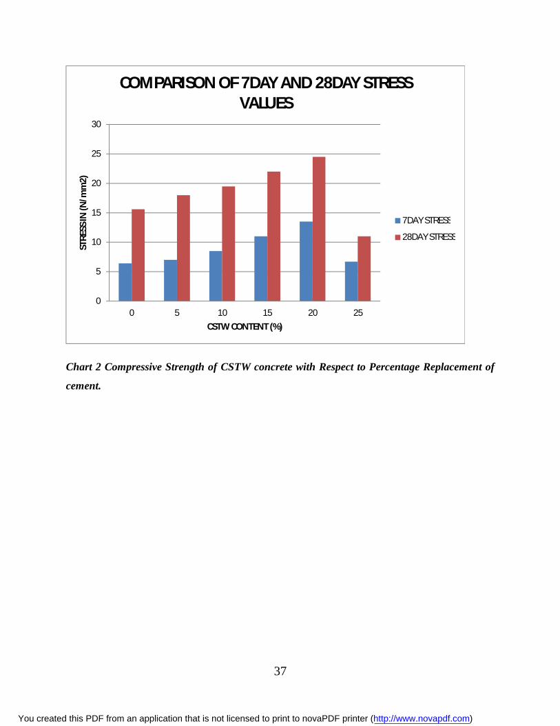
Chart 2 Compressive Strength of CSTW concrete with Respect to Percentage Replacement of
cement.
0
5
10
15
20
25
30
0 5 10 15 20 25
STRE
SS IN
(N/m
m2)
CSTW CONTENT (%)
COMPARISON OF 7DAY AND 28DAY STRESS VALUES
7DAY STRESS
28DAY STRESS
You created this PDF from an application that is not licensed to print to novaPDF printer (http://www.novapdf.com)

38
4.4Tensile strength The results of the splitting tensile tests are shown below
Sample
Label
CSTW
CONTENT
%
7 DAYS 28 DAYS
LOAD
(KN)
STRESS
(N/mm2)
LOAD
(KN)
STRESS
(N/mm2)
TC
(Control)
0 45 0.63 70 1.06
T1 5 60 0.84 85 1.20
T2 10 75 1.06 90 1.27
T3 15 90 1.27 130 1.83
T4 20 95 1.34 145 2.05
T5 25 55 0.78 70 0.99
Table 9 showing the tensile strength test results
You created this PDF from an application that is not licensed to print to novaPDF printer (http://www.novapdf.com)

39
Chart 3 Tensile Strength of CSTW concrete with Respect to Percentage Replacement of
cement.
0
0.5
1
1.5
2
2.5
0 5 10 15 20 25
STRE
SS (N
/mm
2)
CSWT CONTENT (%)
VARIATION OF STRESS VALUES WITH CWST% AT 7 AND 28 DAYS
7 DAY TENSILE STRESS
28DAY TENSILE STRESS
You created this PDF from an application that is not licensed to print to novaPDF printer (http://www.novapdf.com)
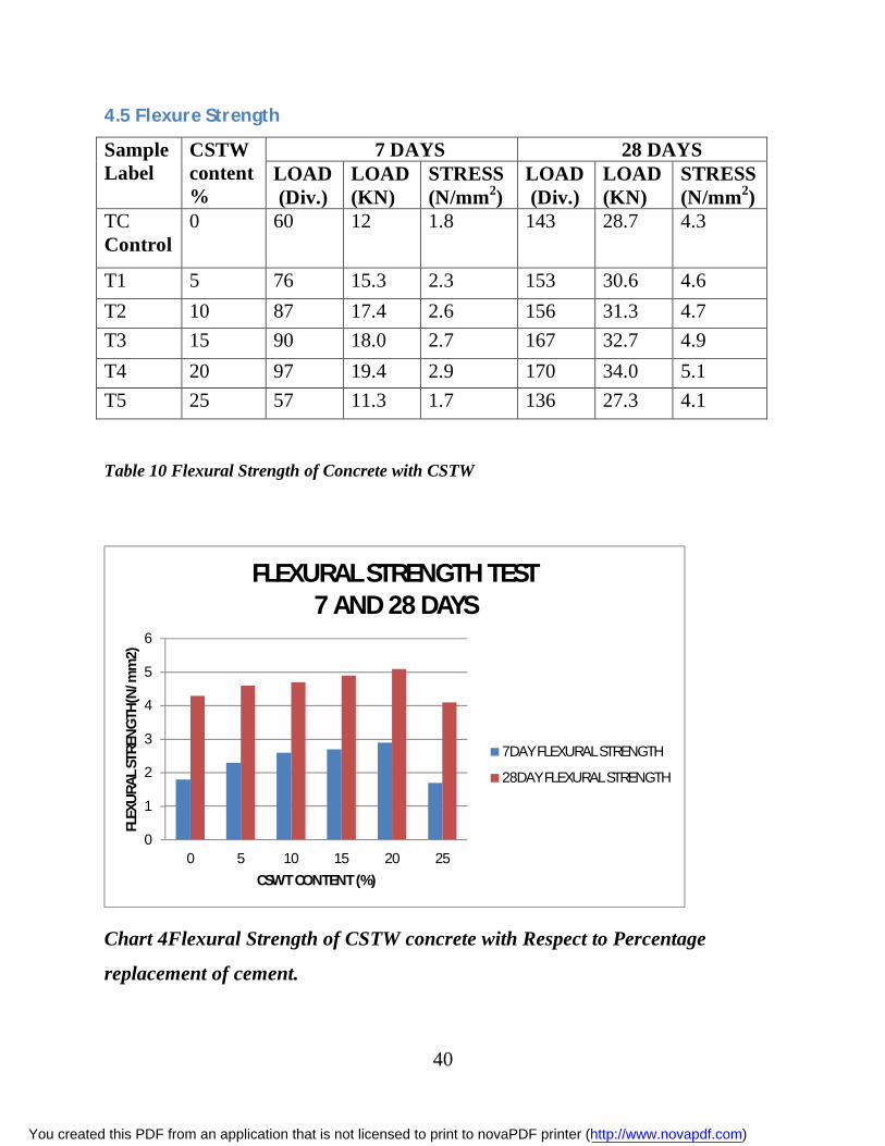
40
4.5 Flexure Strength
Sample Label
CSTW content %
7 DAYS 28 DAYS LOAD (Div.)
LOAD (KN)
STRESS (N/mm2)
LOAD (Div.)
LOAD (KN)
STRESS (N/mm2)
TC Control
0 60 12 1.8 143 28.7 4.3
T1 5 76 15.3 2.3 153 30.6 4.6 T2 10 87 17.4 2.6 156 31.3 4.7 T3 15 90 18.0 2.7 167 32.7 4.9 T4 20 97 19.4 2.9 170 34.0 5.1 T5 25 57 11.3 1.7 136 27.3 4.1
Table 10 Flexural Strength of Concrete with CSTW
Chart 4Flexural Strength of CSTW concrete with Respect to Percentage
replacement of cement.
0
1
2
3
4
5
6
0 5 10 15 20 25
FLEX
URA
L STR
ENG
TH(N
/mm
2)
CSWT CONTENT (%)
FLEXURAL STRENGTH TEST7 AND 28 DAYS
7DAY FLEXURAL STRENGTH
28DAY FLEXURAL STRENGTH
You created this PDF from an application that is not licensed to print to novaPDF printer (http://www.novapdf.com)

41
CHAPTER FIVE
5.0 Discussion
5.1 Workability
5.1.1 Compaction
From the compaction factor tests, it was shown that additional of CSTW reduced the workability
of the fresh concrete. This is attributed to the fact that the CSTW powder added absorbs some of
the water in the concrete mix making the mix be of less flow. From the results recorded on table
6, it can be noted that the compaction factor decreased significantly with an increased in the
percentage replacement of cement by CSTW.25% replacement of cement by CSTW produced
the least compaction factor of 0.87 while the control sample produced the highest factor of 0.95.
This translates close to 10% loss in compaction factor.
5.1.2 Slump test In all the experiments done under this study, true slumps were achieved. From the results
recorded on table 7, is can be noted that an increase in CSTW percentage content in the concrete
leads to a reduction in the slump. The control sample with 0% CSTW content recorded the
highest slump test of 120 mm while the sample with the highest CSTW content registered the
lowest slump of 67 mm.
From the results recorded from both compaction factor test and slump test, it is a clear indication
that an increase in the CSTW content lowers the workability of a fresh concrete. This is mainly
because of the fact that CSTW powder absorbs water. The main factors affecting the workability
are water and additives contents of the mix. Water in the concrete mix lubricates the surface of
aggregates and thus reduces the internal friction resulting in the improved workability.
Water is essential mainly for two defined purposes;
i. To give the required rheological properties/workability.
ii. Participates in the reaction of the cement hydration/chemical reaction with
cement.
You created this PDF from an application that is not licensed to print to novaPDF printer (http://www.novapdf.com)

42
From the past research carried out, evidence has is that only 25% to 30% of water by weight of
cement will react with the cement. The ideal concrete should, therefore, have only this minimal
possible quantity of water necessary to develop the maximum possible strength of the cement,
while providing sufficient workability for placement. However, since cement particles have a
strong tendency to flocculate when they get in contact with water, it becomes necessary to add
more water than is estimated in order to obtain level of workability.
Workability
Workability is the ability of a fresh (plastic) concrete mix to fill the form/mold properly with the
desired work (vibration) and without reducing the concrete's quality. Workability depends on
water content, aggregate (shape and size distribution), cementitious content and age (level of
hydration), and can be modified by adding chemical admixtures.
Raising the water content or adding chemical admixtures will increase concrete workability.
Excessive water will lead to increased bleeding (surface water) and/or segregation of aggregates
(when the cement and aggregates start to separate), with the resulting concrete having reduced
quality[17]. The use of an aggregate with an undesirable gradation can result in a very harsh mix
design with a very low slump, which cannot be readily made more workable by addition of
reasonable amounts of water.
Workability can be measured by the Concrete Slump Test, a simplistic measure of the plasticity
of a fresh batch of concrete following the ASTM C 143 or EN 12350-2 test standards. Slump is
normally measured by filling an "Abrams cone" with a sample from a fresh batch of concrete.
The cone is placed with the wide end down onto a level, non-absorptive surface. It is then filled
in three layers of equal volume, with each layer being tamped with a steel rod in order to
consolidate the layer. When the cone is carefully lifted off, the enclosed material will slump a
certain amount due to gravity. A relatively dry sample will slump very little, having a slump
value of one or two inches (25 or 50 mm). A relatively wet concrete sample may slump as much
as six or seven inches (150 to 175 mm)[7].
Slump can be increased by adding chemical admixtures such as mid-range or high-range water
reducing agents (super-plasticizers) without changing the water/cement ratio. It is bad practice to
add excessive water upon delivery to the jobsite; however in a properly designed mixture it is
important to reasonably achieve the specified slump prior to placement as design factors such as
You created this PDF from an application that is not licensed to print to novaPDF printer (http://www.novapdf.com)

43
air content, internal water for hydration/strength gain, etc. are dependent on placement at design
slump values.
High-flow concrete, like self-consolidating concrete, is tested by other flow-measuring methods.
One of these methods includes placing the cone on the narrow end and observing how the mix
flows through the cone while it is gradually lifted.
5.2 Mechanical characteristics Mechanical characteristics of a hardened concrete is established through test of its compression,
flexural and tensile strength. Going by the results obtained in the tests carried out, it can be stated
that an increase in the percentage replacement of cement weight by the CSTW improves the
mechanical strength of a hardened concrete.
5.2.1 Compression strength From the results obtained from the compressive strength test, it can be noted that an increase in
the CSTW content in the concrete mix results to an increase in the compressive strength of
hardened concrete. This increment is consistent from zero percentage content to a certain
percentage of the CSTW where any further increase causes a drastic reduction in the
compressive strength of the hardened concrete.
From the table 8 and the bar graph in chart 2, it can be seen that as the replacement percentage of
the CSTW increases, the compressive strength also increases. The compressive strength is more
for concrete with an added CSTW as compared to the conventional concrete. The compressive
strength test showed that concrete incorporating 5%-20% of the CSTW as a cement replacement
had somewhat higher compressive strength compared with the control Portland cement concrete
of the same water-to-cementitious material ratio. With replacement of above 20% of cement by
CSTW, the compressive strength of concrete decreased compared to the control concrete. The
sample with 20% recorded 24.5 N/mm2 which is an increase compared to the 15.6% N/mm2
obtained from the control sample. The sample with 25% of the CSTW as the cement replacement
recorded the lowest value of 11% N/mm2.
You created this PDF from an application that is not licensed to print to novaPDF printer (http://www.novapdf.com)

44
The above phenomena can be explained by various chemical reactions that take place in the mix.
Concrete is a structural material which consists of Portland cement, aggregate (sand and rock),
and water. It is believed that the compressive strength of concrete is influenced by the curing
conditions, specimen preparation, age at testing, mode of testing, and mode of failure of the
specimen (Neville and Brooks, 1987).
The main and the most important mineral content of Portland cement are the calcium silicates,
C3S and C2S. These silicates hydrate as follows:
2C3S + 6H → C3S2H3 + 3CH
2C2S + 4H → C 3S 2H + CH
2C3S + 2C2S + 10H → 2C3S2H3+ 4CH
In the presence of CSTW that contains the high percentage of SiO2, the SiO2 will combine with
the released Ca(OH)2.
2 SiO2 + 3CH → C3S2H3
This means that the Ca(OH)2 is being depleted from the system. It is very essential that the
hydrated cement should have a pH of 13±1 otherwise the hydrated silicates and aluminates will
be destabilized thereby causing the weakening of the cement structure which explains the
reduction of the compressive strength with the increase in concentration of CSTW above 25%
replacement of cement[16].
NOTE: Downgrading of concrete mix. From the results of the compressive strength
tests, the grade of the concrete mix was downgraded from Grade 25 to Grade 15 on
the principle that the concrete grade is the strength achieved by the control
(unreinforced/plain concrete mix) at 28days of age. The strength achieved was
15.6N/mm2.The downgrading was necessary since cubes of 100x100x100mm size
were used instead of the standard cubes of 150x150x150mm.The size of coarse
aggregate used was also smaller i.e. 10mm instead of the standard 20mm.Hence,it
was not possible to achieve a Grade 25 (25N/mm2) mix.
You created this PDF from an application that is not licensed to print to novaPDF printer (http://www.novapdf.com)
45
5.2.2 Tensile strength Table 9gives the results of the days and 28 days tensile tests on cylinder specimens. The results
obtained can be interpreted that, an addition of CSTW in the concrete increases the tensile
strength of the concrete specimens. This tensile increase with an increase in the CSTW content is
a trend that breaks off when the increase surpasses 25% CSTW of cement replacement. The mix
with 20% content of CSTW recorded the highest increase tensile strength as compared to the
control mix sample.
5.2.3 Flexural strength
From the test results in table 10, it is evident that addition of CSTW in concrete increases the
flexural/bending strength of a hardened concrete. The flexural strength increases significantly as
the CSTW percentage content increases as at 7 and 28 days of curing.
From the table 10 and chart 4, it can be seen that as the replacement percentage increases, the
Flexural Strength also increases. The Flexural Strength is more for the concrete with a CSTW
content of 5% compared to conventional concrete. The percentage increase in strength is 18.6%
more for the sample with 20% replacement compared to the conventional specimen. However,
this increase stops at some given percentage level, any percentage beyond 20%.
You created this PDF from an application that is not licensed to print to novaPDF printer (http://www.novapdf.com)

46
5.3 Conclusion The set specific objectives of the project were to;
To determine the effects of using CSTW as a natural mineral admixture on both the
mechanical and the workability characteristics of concrete.
Establish the optimum content use of CSTW resulting to better concrete characteristics.
Based on the objectives of the study, it can be concluded that,
I. Addition of CSTW has a negative effect to the workability of a fresh concrete. It
generally lowers the workability of the concrete.
II. Inclusion of CSTW as an admixture in the preparation of concrete improves the
mechanical characteristics of concrete.
The compressive strength increased by significantly. The highest compressive
strength of 24.5N/mm2was recorded for the mix 20% content of CSTW.
Additions of CSTW also increase the tensile strength of the concrete mass with
the highest increase being recorded for the sample with 20% of the CSTW
replacement of cement.
Flexural strength of the concrete was also increased by addition of CSTW into the
concrete mix with as high as 18.6% in the case of 20% CSTW content as at
28days of curing.
5.4 RECOMMENDATIONS Utilization of the CSTW from both the quarries and the clay industries is essential in order to
minimize the waste and the environmental considerations. Moreover, it is an effective utilization
of the limited natural resources like cement. Therefore, efforts of crating awareness among the
stakeholders in the engineering sector on the benefits of using the waste products should put in
place. This is an alternative solution to waste disposal while at the same time improving the
mechanical properties of concrete.
From the results, it was concluded that adding CSTW lowers the workability of concrete. This
set back can be easily addressed through use of super plasticizers admixtures which significantly
improve the workability of fresh concrete.
You created this PDF from an application that is not licensed to print to novaPDF printer (http://www.novapdf.com)

47
Super plasticizers are also known as high-range water reducers. They are classified as Type F by
ASTMC [6]. Super plasticizers meet ASTMC 1017 & and C494 standards. They promote grate
flow-ability without substantially slowing the set time or increasing air entrainment. Super
plasticizers are incorporated to achieve as minimal demand for water as possible. Hence, the
names water reducers and high range water reducer are derived from reducing the huge volumes
of water required in the concrete. Plasticizers dosage varies by the particular concrete and type of
plasticizer used.
Finally, more research should be done on this topic to establish use of more waste products that
have posed a degradation threat to the environment.
You created this PDF from an application that is not licensed to print to novaPDF printer (http://www.novapdf.com)

48
6.0 REFERENCES: 1. Almeida Nuno, Branco Fernando, Santos José Roberto, 2007, Recycling of stone slurry in
industrial activities: Application to concrete mixtures, Building and Environment, 42(2):
810-819.
2. Ammary, B., 2007. Clean cutting stone industry. International Journal of Environment
and Waste Management, 1 (2/3): 106-112.
3. Arslan E. I I, AslanSibel, IpekUbeyde, AltunSamet, YazicioluSalih, 2005, Physico-
chemical treatment of marble processing wastewater and the recycling of its sludge.
Waste Management & Research, 23( 6): 550- 559. 24
4. Babu K.K., Radhakrishnan R. and Nambiar E.K.K. 1997. Compressive Strength of Brick
Masonry with Alternative - Aggregate Mortar. CE and CR Journal, New Delhi.
5. Colombo A. , Tunesi A., Barberini V., Galimberti L., Cavallo A., Chemical and
mineralogical characterization of cutting process sludge , exploitation of sludge from
stone working synthesis of the research. Accessed 2008,http://www.aigt.ch/ download/
rapporto_INTERREGen. Pdf.
6. Concrete Admixtures Handbook (2), Properties, Science, and Technology 1996.
7. Connan, H., Klimesch, D., Rayt, A., and Thomas, P., 2005, Autoclaved opc-quartz blends
incorporating clay-brick waste. part i: factorial design effects on strength development,
Advances in Cement Research, 17(4):133-141.
8. G. Kaur, S. P. Singh And S. K. Kaushik, “Reviewing Some Properties of Concrete
Containing Mineral Admixtures” Indian Concrete Journal July 2012, 35-49.
9. Hajime Okamura and Masahiro Ouchi, “Properties of Concrete”, Journals of Advanced
Concrete Technologies, Vol. 1, No. 1 April 2003, pp. 5-15.
10. http://concreteproducts.com
11. Ilangovan R. and Nagamani K. 2006. Application of quarry Rock dust as fine aggregate
in concrete construction. National Journal on construction Management: NICMR. Pune.
December.
12. Ilangovan R. and Nagamani K. 2006. Studies on Strength and Behavior of Concrete by
using Quarry Dust as Fine Aggregate. CE and CR Journal, New Delhi.
You created this PDF from an application that is not licensed to print to novaPDF printer (http://www.novapdf.com)

49
13. M. RameGowda, Mattur C. Narasimhan and Karisiddappa, Strength behavior of self-
compacting concrete mixes using local materials. The Indian concrete journal, July 2012,
54-60.
14. M.S. Shetty, “Concrete Technology”, S. Chand.
15. Mehta P. Monteiro P. Concrete Microstructure, Properties, and Materials. Prentice hall,
Inc. Third Edition. 2005.
16. Mehta, P. K., “Rice Husk Ash-A Unique Supplementary Cementing Material,”
Proceedings of the International Symposium on Advances in Concrete Technology, ed.
V. M. Malhotra, Athens, Greece, May 1992, pp. 407-430. [12]. Cook, D. J., “Rice Husk
Ash,” Concrete Technology and Design: Vol. 3, Cement Replacement Materials, Ed.
R.N. Swamy, published by Surrey University Press, 1986, pp.l71-196. 23
17. Mindess S. Young J. Concrete. Civil Engineering and Engineering Mechanics Series.
Second Edition. 1981.
18. Misra A., Gupta R., Gupta R.C., Utilization of marble slurry in construction materials,
Workshop on gainful utilization of marble slurry and other stone waste. Indian School of
Mines, accessed 2008, http://www.cdosindia.com/papers/marble_slurry_
workshop/anurag_ mishra _-_utilisation_of _marble_slurry _in_ construction .doc.
19. Nans, Kung-chung HSU, His Wen Chai, “A Simple Mix Design, Method For Self
Compacting Concrete (2001) 1799 – 1807.
20. Narasimhan C., Patil B.T. and Sankar H. Sanni. 1999. Performance of Concrete with
Quarry Dust as Fine Aggregate-An Experimental Study. CE and CR Journal.
21. Nataraja M.C., Nagaraj T.S. and Reddy. A. 2001. Proportioning Concrete Mix with
Quarry Wastes Cement. Concrete and Aggregate Journal, ASTM.
22. Nisnevich M. Sirotin G. and Eshel Y. 2003. Light weight concrete containing thermal
power station and stone quarry waste. Magazine of Concrete Research.
23. S. Bhaskar, RavindraGettu, B. H. Bharatkumar and M.Neelamegam, Strength, bond and
durability related properties of concretes with mineral admixtures. The Indian concrete
journal, February 2012.
24. Sahu A.K., Sunil Kumar and Sachan A.K. 2003. Quarry Stone Waste as Fine aggregate
for concrete. The Indian Concrete Journal.
You created this PDF from an application that is not licensed to print to novaPDF printer (http://www.novapdf.com)

50
25. Turgut, P. and Algin, H.M., 2007. Limestone dust and wood sawdust as brick material.
Building and Environment Journal, 42 (9): 3399-3403.
26. Vilas V. Karjinni, Shrishail B. Anandinni and Dada S. Patil, An investigation on the
characteristic properties of high performance SCC with mineral admixtures. The Indian
Concrete Journal, 2009, 15-19.
27. www.microsilicachina.com
28. Zhang, M. H. and Malhotra, V. M., “High-Performance Concrete Incorporating Rice
Husk Ash as a supplementary Cementing Materials,” accepted for publication in the AU
Materials Journal.
29. ZoranGrdic, Iva Despotovic, GordanaToplicicCurcic, 2008. Properties of Self
Compactability Concrete with Different types of Additives, FACTA University,
Architecture and Civil Engineering, Vol. 6, 173-177.
You created this PDF from an application that is not licensed to print to novaPDF printer (http://www.novapdf.com)

51
7. APPENDIXES I This appendix contains line graphs of all the tests performed,for easier observation and
comparison.
Chart Line graph showing the7 and 28days compressive stress with varying CSTWcontent.
Chart Line graph showing the7 and 28days tensile stress with varying CSTW content.
0
5
10
15
20
25
30
0 5 10 15 20 25 30
Com
pres
sive
stre
ss (N
/mm
2)
CSWT CONTENT (%)
Comparison of 7 and 28 daysstress value
7DAYS STRESS
28DAYS STRESS
0
0.5
1
1.5
2
2.5
0 5 10 15 20 25 30
TEN
SILE
STR
ESS
(N/m
m2)
CSTW CONTENT (%)
VARIATION OF STRESS VALUE WITH CSTW CONTENT
7DAY STRESS
28DAY STRESS
You created this PDF from an application that is not licensed to print to novaPDF printer (http://www.novapdf.com)

52
Chart Line graph showing the7 and 28days flexural stress with varying CSTW content.
0
1
2
3
4
5
6
0 5 10 15 20 25 30FLEX
URA
L STR
ESS
(N/m
m2)
CSTW CONTENT (%)
VARIATION OF STRESS WITH CSTW CONTENT
7DAY STRESS
28DAY STRESS
You created this PDF from an application that is not licensed to print to novaPDF printer (http://www.novapdf.com)